a finite element parametric study of reinforced concrete
TRANSCRIPT

A Finite Element Parametric Study of Reinforced Concrete Horizontally Circular Deep Beams
A. A. Talal1, W. H. Khaleel1, B. N. Hassan1, K. S. Abdul-Razzaq1,a*, and A. A. Dawood1
1Civil Engineering Department, University of Diyala, Diyala, 32001, Iraq. [email protected]
Abstract. A parametric study of twenty-five reinforced concrete ring deep beams using finite element analysis is presented in this study. This paper took into account the kind of loading (partial and complete), the diameter, depth, and width of the ring beam, as well as the NO. of supports. When compared to equivalent concentrated central loading, acting a central partial distributed loading of 25-100 percent of the length of span increased capacity of load by about 3-80 percent while decreasing max. deflection and moments of torsion by about 4-14 percent and 1-9 percent, respectively. Decreases in load capacity of about 10-33 percent were observed when beam diameter was increased by 20-80%, while deflection and moments of torsion increased by about 30-145 percent and 8-23 percent, respectively. When the depth of the beam was increased by 12-50 percent, the capacity of load and moments of torsion increased by about 15-61 percent, while deflection reduced by about 8-21 percent. When the circular beam width was increased by 40-160 percent, the capacity of load, deflection, and moments of torsion increased by about 142-690 percent, 26-62 percent, and 137-662 percent, respectively. Finally, when the NO. of supports increased by 25-150 percent, the capacity of load increased by about 70-380 percent, while the deflection and moments of torsion decreased by about 27-71 percent and 16-72 percent, respectively.
Keywords: Circular beam; deep beam; reinforced concrete; numerical analysis; finite element.
Introduction In addition to their traditional utilized in curved structures, ring beams are now commonly utilized
in the construction of ring foundations, domes, and base tanks, as well as for aesthetic purposes [1]. When loaded transversely to their planes, these beams are influenced to bending, shear and torsion. As a result, a unique characteristic of the design and analysis is the requirement to consider together effects. Even at service load, cracks form in reinforced concrete structures. Internal forces redistribution occurs as a result of cracking, which makes local reductions in values of flexural and torsional stiffness.
Multiple supports frequently support deep, circular beams of reinforced concrete. The ACI 318M-14 Code exhibits deep beams as [2]: " members of structure loaded on one face and supported on the opposite face, allowing stresses of shear to grow between the loads and supports. That achieves (a) or (b): (a) Single load are 2h far from the face of support.; and (b) The depth of member (h) is not more than four times the clear span''. However, the majority of existing research into the behavior of structure and deep members’ strength has been limited to deep beams of single span [3-7] and continuous deep beams [8-13], pile caps [14-15], corbels [16-23] but not take care on ring deep beams.
Finite element analysis and design of reinforced concrete members is a handy tool [24-30]. In structural engineering, deep circular beams are very prevalent. However, there are few studies on them. As a result, this research provided a computational report for findings of twenty-five reinforced concrete ring deep beams to discover the effects of kind of load, the radius of the beam, depth of the beam, the width of the beam, and the NO. of supports on the capacity of load, deflection, moments torsion, and location of failure.
E3S Web of Conferences 318, 03013 (2021) https://doi.org/10.1051/e3sconf/202131803013ICGE 2021
© The Authors, published by EDP Sciences. This is an open access article distributed under the terms of the Creative Commons Attribution License 4.0 (http://creativecommons.org/licenses/by/4.0/).

Model of Finite Element The methodology comprises using the ETABS software to investigate the parametric effect on
deep circular beams. The entire project is broken down into the steps below.
Modeling. For predicting the behavior of structural elements, three-dimensional ]3D [ finite element ]FE[ analysis has turn out a common option. ETABS software was used to construct the models. The beams are designed utilizing the maximum load capacity following ACI 318-14. The vertical slice mesh has 120-126 elements along the circular axis, which was determined based on convergence tests to find the best mesh that provides a moderately accurate solution while consuming minimal computational time. Steel was considered an elastic completely plastic material in both compression and tension in the current study. The findings of the analysis were acquired and assessed. There was always one pin support at the boundary, while the rest were roller supports.
Study cases of Reinforced concrete ring deep beam. The twenty-five circular reinforced concrete deep beams are all designed the same way. They are separated depended on five variables. The first variable included five beams with various kinds of loading, namely uniformly or concentrated vertically (complete or partial) loading at 25%, 50%, 75%, and 100% of the span length. various variables concerning ring deep beam dimensions are also computed, in addition to loading type. The second parameter consisted of five different diameter beams: 5000, 6000, 7000, 8000, and 9000 mm. The third variable consisted of five beams with varying depths of beam: 1600, 1800, 2000, 2200, and 2400 mm. The fourth variable consisted of four beams with different beam widths: 250, 350 mm, 450, 550, and 650 mm. lastly, the fifth variable consisted of five beams with varying numbers of evenly spaced supports: 4, 5, 6, 8, and 10. In 3D modeling, a deep circular beam is shown in Figure 1.
Figure 1. (a) Ring Beam under complete uniformly distributed load.
2
E3S Web of Conferences 318, 03013 (2021) https://doi.org/10.1051/e3sconf/202131803013ICGE 2021

Model of Finite Element The methodology comprises using the ETABS software to investigate the parametric effect on
deep circular beams. The entire project is broken down into the steps below.
Modeling. For predicting the behavior of structural elements, three-dimensional ]3D [ finite element ]FE[ analysis has turn out a common option. ETABS software was used to construct the models. The beams are designed utilizing the maximum load capacity following ACI 318-14. The vertical slice mesh has 120-126 elements along the circular axis, which was determined based on convergence tests to find the best mesh that provides a moderately accurate solution while consuming minimal computational time. Steel was considered an elastic completely plastic material in both compression and tension in the current study. The findings of the analysis were acquired and assessed. There was always one pin support at the boundary, while the rest were roller supports.
Study cases of Reinforced concrete ring deep beam. The twenty-five circular reinforced concrete deep beams are all designed the same way. They are separated depended on five variables. The first variable included five beams with various kinds of loading, namely uniformly or concentrated vertically (complete or partial) loading at 25%, 50%, 75%, and 100% of the span length. various variables concerning ring deep beam dimensions are also computed, in addition to loading type. The second parameter consisted of five different diameter beams: 5000, 6000, 7000, 8000, and 9000 mm. The third variable consisted of five beams with varying depths of beam: 1600, 1800, 2000, 2200, and 2400 mm. The fourth variable consisted of four beams with different beam widths: 250, 350 mm, 450, 550, and 650 mm. lastly, the fifth variable consisted of five beams with varying numbers of evenly spaced supports: 4, 5, 6, 8, and 10. In 3D modeling, a deep circular beam is shown in Figure 1.
Figure 1. (a) Ring Beam under complete uniformly distributed load.
Figure 1. (b) Ring Beam under central concentrated load.
Figure 1. (c) Ring Beam under partial uniformly distributed load.
Properties of material. Ring deep beams are constructed of two materials: steel reinforcement and concrete. Each kind of element in this modeling was utilized to act the constituents of a specific beam. The geometrical properties of the utilized elements, such as area of cross-section, are required for the real constants. At the same time, the required material properties base on mechanical inspections such as stress of yield of main reinforcement (fy), compressive strength (f'c), stress of yield of web reinforcement (fys), concrete elasticity modulus (Ec), Poisson`s ratio (ν), and steel reinforcement elasticity modulus (Es). Table 1 lists the properties of material of deep ring beams.
Table 1. Properties of material.
Ec (MPa)
Es (GPa)
f'c (MPa)
Poisson`s ratio (ν)
Lightweight Concrete factor (Unit less)
fy (MPa)
fys (MPa)
25743 200 30 0.2 1 420 420
3
E3S Web of Conferences 318, 03013 (2021) https://doi.org/10.1051/e3sconf/202131803013ICGE 2021
Parametric Study The findings of the maximum value of load, max. deflection, max. moments of torsion, and site of
failure of total beams are found in the following items using ETABS software. The comparison of the first beam (reference beam) in Table 1 was used to calculate all parametric effect values.
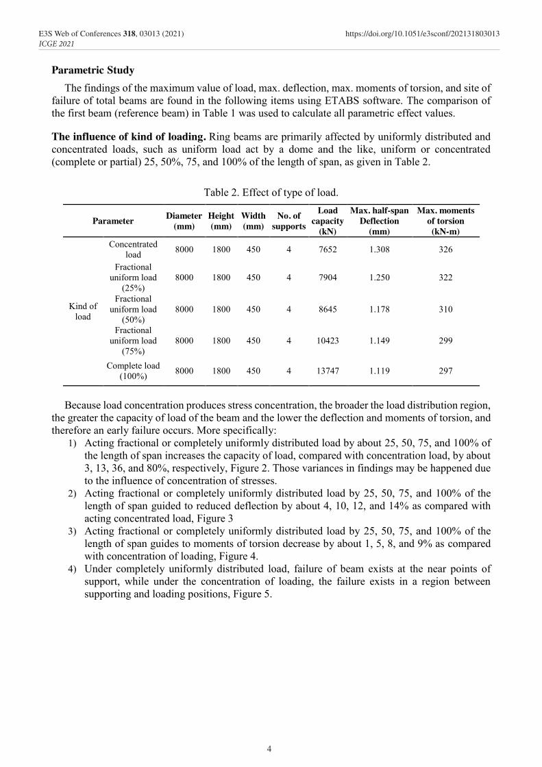
The influence of kind of loading. Ring beams are primarily affected by uniformly distributed and concentrated loads, such as uniform load act by a dome and the like, uniform or concentrated (complete or partial) 25, 50%, 75, and 100% of the length of span, as given in Table 2.
Table 2. Effect of type of load.
Parameter Diameter (mm)
Height (mm)
Width (mm)
No. of supports
Load capacity
(kN)
Max. half-span Deflection
(mm)
Max. moments of torsion (kN-m)
Kind of load
Concentrated load 8000 1800 450 4 7652 1.308 326
Fractional uniform load
(25%) 8000 1800 450 4 7904 1.250 322
Fractional uniform load
(50%) 8000 1800 450 4 8645 1.178 310
Fractional uniform load
(75%) 8000 1800 450 4 10423 1.149 299
Complete load (100%) 8000 1800 450 4 13747 1.119 297
Because load concentration produces stress concentration, the broader the load distribution region,
the greater the capacity of load of the beam and the lower the deflection and moments of torsion, and therefore an early failure occurs. More specifically:
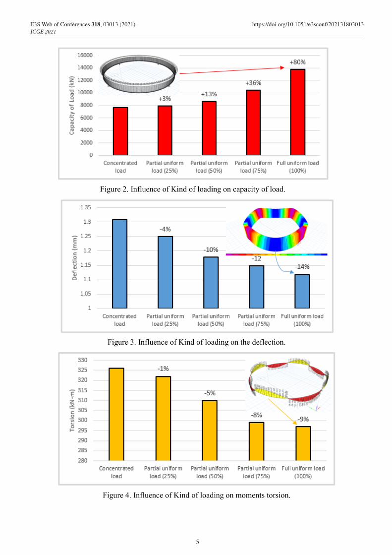
1) Acting fractional or completely uniformly distributed load by about 25, 50, 75, and 100% of the length of span increases the capacity of load, compared with concentration load, by about 3, 13, 36, and 80%, respectively, Figure 2. Those variances in findings may be happened due to the influence of concentration of stresses.
2) Acting fractional or completely uniformly distributed load by 25, 50, 75, and 100% of the length of span guided to reduced deflection by about 4, 10, 12, and 14% as compared with acting concentrated load, Figure 3
3) Acting fractional or completely uniformly distributed load by 25, 50, 75, and 100% of the length of span guides to moments of torsion decrease by about 1, 5, 8, and 9% as compared with concentration of loading, Figure 4.
4) Under completely uniformly distributed load, failure of beam exists at the near points of support, while under the concentration of loading, the failure exists in a region between supporting and loading positions, Figure 5.
4
E3S Web of Conferences 318, 03013 (2021) https://doi.org/10.1051/e3sconf/202131803013ICGE 2021
Parametric Study The findings of the maximum value of load, max. deflection, max. moments of torsion, and site of
failure of total beams are found in the following items using ETABS software. The comparison of the first beam (reference beam) in Table 1 was used to calculate all parametric effect values.
The influence of kind of loading. Ring beams are primarily affected by uniformly distributed and concentrated loads, such as uniform load act by a dome and the like, uniform or concentrated (complete or partial) 25, 50%, 75, and 100% of the length of span, as given in Table 2.
Table 2. Effect of type of load.
Parameter Diameter (mm)
Height (mm)
Width (mm)
No. of supports
Load capacity
(kN)
Max. half-span Deflection
(mm)
Max. moments of torsion (kN-m)
Kind of load
Concentrated load 8000 1800 450 4 7652 1.308 326
Fractional uniform load
(25%) 8000 1800 450 4 7904 1.250 322
Fractional uniform load
(50%) 8000 1800 450 4 8645 1.178 310
Fractional uniform load
(75%) 8000 1800 450 4 10423 1.149 299
Complete load (100%) 8000 1800 450 4 13747 1.119 297
Because load concentration produces stress concentration, the broader the load distribution region,
the greater the capacity of load of the beam and the lower the deflection and moments of torsion, and therefore an early failure occurs. More specifically:
1) Acting fractional or completely uniformly distributed load by about 25, 50, 75, and 100% of the length of span increases the capacity of load, compared with concentration load, by about 3, 13, 36, and 80%, respectively, Figure 2. Those variances in findings may be happened due to the influence of concentration of stresses.
2) Acting fractional or completely uniformly distributed load by 25, 50, 75, and 100% of the length of span guided to reduced deflection by about 4, 10, 12, and 14% as compared with acting concentrated load, Figure 3
3) Acting fractional or completely uniformly distributed load by 25, 50, 75, and 100% of the length of span guides to moments of torsion decrease by about 1, 5, 8, and 9% as compared with concentration of loading, Figure 4.
4) Under completely uniformly distributed load, failure of beam exists at the near points of support, while under the concentration of loading, the failure exists in a region between supporting and loading positions, Figure 5.
Figure 2. Influence of Kind of loading on capacity of load.
Figure 3. Influence of Kind of loading on the deflection.
Figure 4. Influence of Kind of loading on moments torsion.
5
E3S Web of Conferences 318, 03013 (2021) https://doi.org/10.1051/e3sconf/202131803013ICGE 2021

Figure 5. Sites of failure due to completed load.
The Influence of dimension variation. Any variation in dimensions of beam has a significant impact on how it sustains the acting load. Dimensions are one of the most important effecting variable to consider, as shown in Table 3.
Table 3. Dimensions Effect
Parameter Diameter (mm)
Depth (mm)
Width (mm)
Number of
supports
capacity of Load
(kN)
Max. half-span deflection
(mm)
Max torsional moments (kN-m)
dimension
diameter
5000 1800 450 4 10456 0.648 274 6000 1800 450 4 9392 0.840 296 7000 1800 450 4 8460 1.059 313 8000 1800 450 4 7652 1.308 326 9000 1800 450 4 6952 1.587 336
height
8000 1600 450 4 6644 1.420 283 8000 1800 450 4 7652 1.308 326 8000 2000 450 4 8660 1.225 369 8000 2200 450 4 9672 1.163 412 8000 2400 450 4 10688 1.116 455
width
8000 1800 250 4 1844 0.918 81 8000 1800 350 4 4472 1.156 192 8000 1800 450 4 7652 1.308 326 8000 1800 550 4 11072 1.411 470 8000 1800 650 4 14580 1.484 617
The effect of diameter. This is the most important variable. Under a single central concentrated load, five beams with different circular diameters were investigated: 5000, 6000, 7000, 8000, and 9000 mm. The Influence of diameter has been studied and it has been discovered that:
1) As shown in Figure 6, increasing the ring diameter by 20-80% reduces the capacity of load by about 10-33%. With the same support number, increasing the diameter increases the displacement between the supporting and loading points, which make high flexural moments.
2) The deflection rose by about 30-145%, rising the ring diameter by about 20-80%, Figure 7 because of the length of span rise.
3) moments of torsion rose by about 8-23%, rising the diameter by 20-80%, Figure 8, because of the length of span rise.
4) The shear and torsion failure modes were observed in total beams between the supporting and loading positions, indicating torsion and shear failure. Figure 9 depicts beam failure with an 8000 mm diameter.
6
E3S Web of Conferences 318, 03013 (2021) https://doi.org/10.1051/e3sconf/202131803013ICGE 2021

Figure 5. Sites of failure due to completed load.
The Influence of dimension variation. Any variation in dimensions of beam has a significant impact on how it sustains the acting load. Dimensions are one of the most important effecting variable to consider, as shown in Table 3.
Table 3. Dimensions Effect
Parameter Diameter (mm)
Depth (mm)
Width (mm)
Number of
supports
capacity of Load
(kN)
Max. half-span deflection
(mm)
Max torsional moments (kN-m)
dimension
diameter
5000 1800 450 4 10456 0.648 274 6000 1800 450 4 9392 0.840 296 7000 1800 450 4 8460 1.059 313 8000 1800 450 4 7652 1.308 326 9000 1800 450 4 6952 1.587 336
height
8000 1600 450 4 6644 1.420 283 8000 1800 450 4 7652 1.308 326 8000 2000 450 4 8660 1.225 369 8000 2200 450 4 9672 1.163 412 8000 2400 450 4 10688 1.116 455
width
8000 1800 250 4 1844 0.918 81 8000 1800 350 4 4472 1.156 192 8000 1800 450 4 7652 1.308 326 8000 1800 550 4 11072 1.411 470 8000 1800 650 4 14580 1.484 617
The effect of diameter. This is the most important variable. Under a single central concentrated load, five beams with different circular diameters were investigated: 5000, 6000, 7000, 8000, and 9000 mm. The Influence of diameter has been studied and it has been discovered that:
1) As shown in Figure 6, increasing the ring diameter by 20-80% reduces the capacity of load by about 10-33%. With the same support number, increasing the diameter increases the displacement between the supporting and loading points, which make high flexural moments.
2) The deflection rose by about 30-145%, rising the ring diameter by about 20-80%, Figure 7 because of the length of span rise.
3) moments of torsion rose by about 8-23%, rising the diameter by 20-80%, Figure 8, because of the length of span rise.
4) The shear and torsion failure modes were observed in total beams between the supporting and loading positions, indicating torsion and shear failure. Figure 9 depicts beam failure with an 8000 mm diameter.
Figure 6. Diameter variation effect on
capacity of load. Figure 7. Diameter variation effect on
deflection.
Figure 8. Diameter variation effect on
torsional moments Figure 9. Location of failure in a beam with
diameter of 8000 mm
The Influence of height. Five beams with various depth values, 1600, 1800, 2000, 2200, and 2400 mm were modeled to discover the influence of depth on the capacity of ring beams that loaded with one concentrated load for each span. The Influence of depth has been studied and it has been discovered that:
1) rising the depth by 12-50% rose the capacity of load by about 15-61% as shown in Figure 10. As the depth of the concrete increases, the area of section of concrete that resists shear increases as well.
2) Figure 11 shows that increasing the depth by 12-50 percent reduced deflection by around 8-21 percent. This happened due to increasing the depth of the beam increases the sectional area of the beam, which increases the resistance of flexural moments.
3) Moments torsion increased by about 15-61%, increasing the depth by 12-50%, as shown in Figure 12. Increased beam depth increases torsional moments due to an increase in the arm of the torsional forces.
4) The failure existed in the region between the supporting and loading positions, indicating that torsion and shear failures occurred. Figure 13 exhibits how the failure of the beam with a depth of 1800 mm existed between supporting and loading positions.
00.20.40.60.8
11.21.41.61.8
0 5000 10000
Defle
ctio
n (m
m)
Diameter of beam (mm)
0
50
100
150
200
250
300
350
400
0 5000 10000
Tors
ion
(kN-
m)
Diameter of beam (mm)
7
E3S Web of Conferences 318, 03013 (2021) https://doi.org/10.1051/e3sconf/202131803013ICGE 2021

Figure 10. Depth Effect on capacity of load. Figure 11. Depth Influence on deflection.
Figure 12. Depth Influence on the moments torsion.
Figure 13. Site of failure in a beam with depth of 1800 mm.
The Influence of beam width. Five beams with varying beam widths were modeled: 250, 350, 450, 550, and 650 mm:
1) As illustrated in Figure 14, increasing beam width by 40-160 percent increases load capacity by 142-690 percent. With increasing width, the concrete area of section that resists acting shear rises.
2) The deflection rose by around 26-62 percent when the width was raised by 40-160 percent, as shown in Figure 15. Increased width guids to the increased capacity of load and, as a result, increased nonlinear deflection.
3) As indicated in Figure 16, the torsional moments rose by around 137-662 percent within reason, increasing the width by 40-160 percent. Because the arm of torsion forces grows as the width rises, the moments of torsion increase.
4) The failure that existed in a region between supporting and loading positions, indicating torsion and shear failure. Figure 17 depicts the failure of a 450-mm-wide beam between the supporting and loading locations.
The effect of the number of support. Five different circular deep beams by a NO. of supports were analyzed to find out the influence of this important variable, Table 4:
1) Increasing the NO. of supports from 4 to 9 resulted in a 70-380% increase in capacity of load, as shown in Figure 18. When the NO. of supports is increased, the shear span length is reduced, and thus the shear capacity is increased.
8
E3S Web of Conferences 318, 03013 (2021) https://doi.org/10.1051/e3sconf/202131803013ICGE 2021
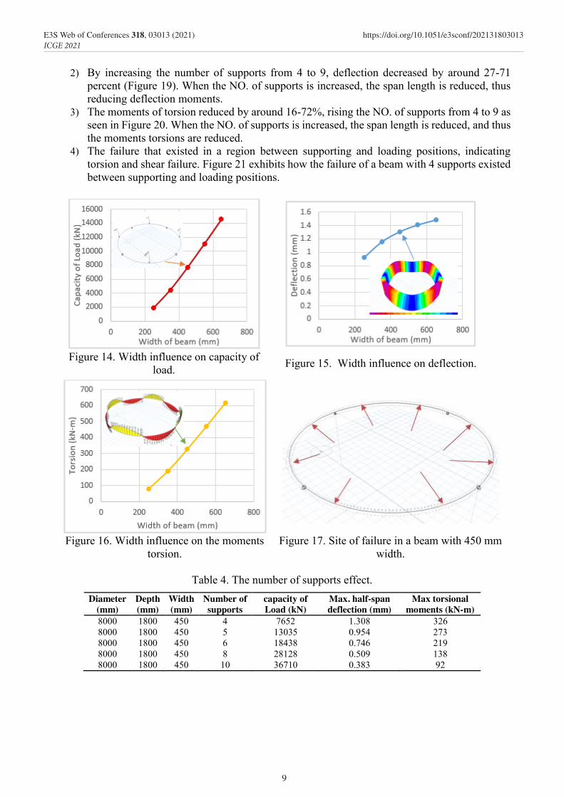
Figure 10. Depth Effect on capacity of load. Figure 11. Depth Influence on deflection.
Figure 12. Depth Influence on the moments torsion.
Figure 13. Site of failure in a beam with depth of 1800 mm.
The Influence of beam width. Five beams with varying beam widths were modeled: 250, 350, 450, 550, and 650 mm:
1) As illustrated in Figure 14, increasing beam width by 40-160 percent increases load capacity by 142-690 percent. With increasing width, the concrete area of section that resists acting shear rises.
2) The deflection rose by around 26-62 percent when the width was raised by 40-160 percent, as shown in Figure 15. Increased width guids to the increased capacity of load and, as a result, increased nonlinear deflection.
3) As indicated in Figure 16, the torsional moments rose by around 137-662 percent within reason, increasing the width by 40-160 percent. Because the arm of torsion forces grows as the width rises, the moments of torsion increase.
4) The failure that existed in a region between supporting and loading positions, indicating torsion and shear failure. Figure 17 depicts the failure of a 450-mm-wide beam between the supporting and loading locations.
The effect of the number of support. Five different circular deep beams by a NO. of supports were analyzed to find out the influence of this important variable, Table 4:
1) Increasing the NO. of supports from 4 to 9 resulted in a 70-380% increase in capacity of load, as shown in Figure 18. When the NO. of supports is increased, the shear span length is reduced, and thus the shear capacity is increased.
2) By increasing the number of supports from 4 to 9, deflection decreased by around 27-71 percent (Figure 19). When the NO. of supports is increased, the span length is reduced, thus reducing deflection moments.
3) The moments of torsion reduced by around 16-72%, rising the NO. of supports from 4 to 9 as seen in Figure 20. When the NO. of supports is increased, the span length is reduced, and thus the moments torsions are reduced.
4) The failure that existed in a region between supporting and loading positions, indicating torsion and shear failure. Figure 21 exhibits how the failure of a beam with 4 supports existed between supporting and loading positions.
Figure 14. Width influence on capacity of
load. Figure 15. Width influence on deflection.
Figure 16. Width influence on the moments torsion.
Figure 17. Site of failure in a beam with 450 mm width.
Table 4. The number of supports effect.
Diameter (mm)
Depth (mm)
Width (mm)
Number of supports
capacity of Load (kN)
Max. half-span deflection (mm)
Max torsional moments (kN-m)
8000 1800 450 4 7652 1.308 326 8000 1800 450 5 13035 0.954 273 8000 1800 450 6 18438 0.746 219 8000 1800 450 8 28128 0.509 138 8000 1800 450 10 36710 0.383 92
9
E3S Web of Conferences 318, 03013 (2021) https://doi.org/10.1051/e3sconf/202131803013ICGE 2021

Figure 18. Influence of a number of supports on the capacity of load.
Figure 19. Influence of a number of supports on a deflection.
Figure 20. Influence of a number of supports on the moments of torsion.
10
E3S Web of Conferences 318, 03013 (2021) https://doi.org/10.1051/e3sconf/202131803013ICGE 2021
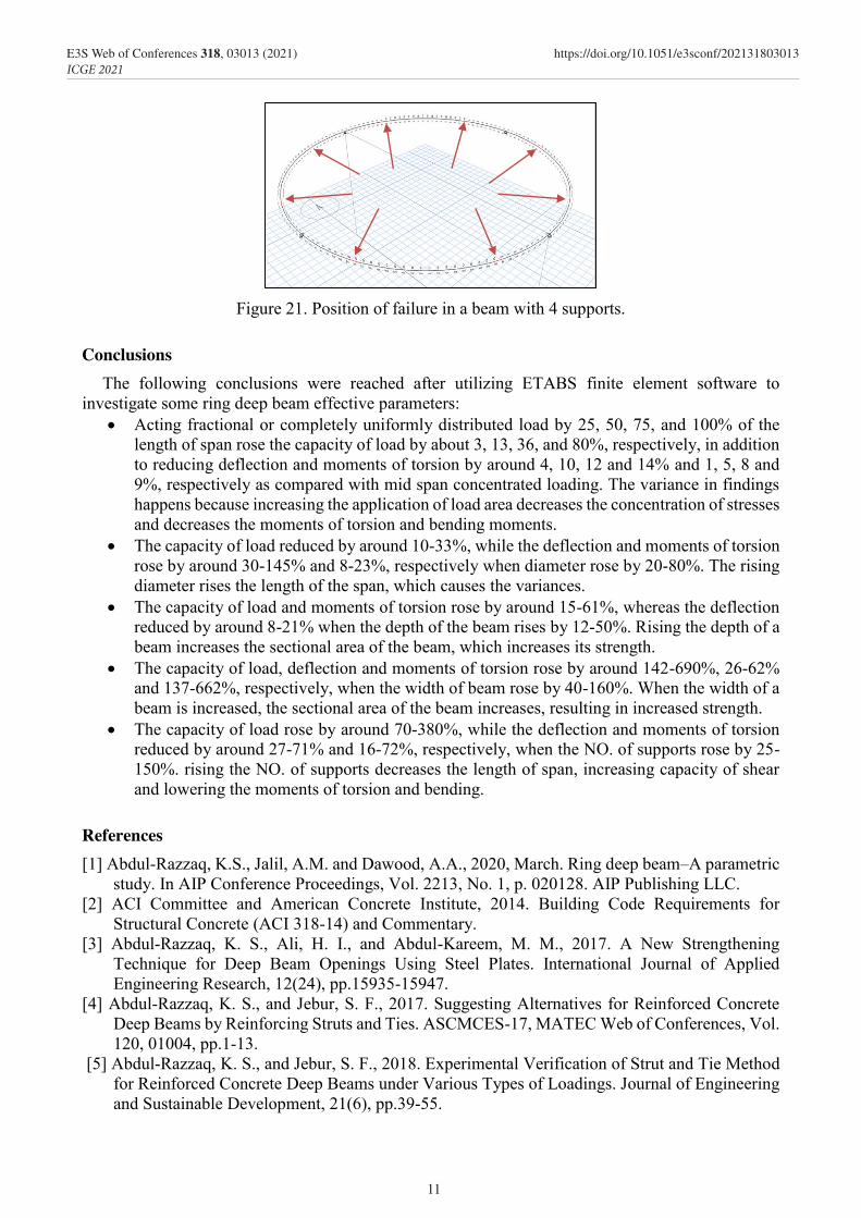
Figure 18. Influence of a number of supports on the capacity of load.
Figure 19. Influence of a number of supports on a deflection.
Figure 20. Influence of a number of supports on the moments of torsion.
Figure 21. Position of failure in a beam with 4 supports.
Conclusions The following conclusions were reached after utilizing ETABS finite element software to
investigate some ring deep beam effective parameters: Acting fractional or completely uniformly distributed load by 25, 50, 75, and 100% of the
length of span rose the capacity of load by about 3, 13, 36, and 80%, respectively, in addition to reducing deflection and moments of torsion by around 4, 10, 12 and 14% and 1, 5, 8 and 9%, respectively as compared with mid span concentrated loading. The variance in findings happens because increasing the application of load area decreases the concentration of stresses and decreases the moments of torsion and bending moments.
The capacity of load reduced by around 10-33%, while the deflection and moments of torsion rose by around 30-145% and 8-23%, respectively when diameter rose by 20-80%. The rising diameter rises the length of the span, which causes the variances.
The capacity of load and moments of torsion rose by around 15-61%, whereas the deflection reduced by around 8-21% when the depth of the beam rises by 12-50%. Rising the depth of a beam increases the sectional area of the beam, which increases its strength.
The capacity of load, deflection and moments of torsion rose by around 142-690%, 26-62% and 137-662%, respectively, when the width of beam rose by 40-160%. When the width of a beam is increased, the sectional area of the beam increases, resulting in increased strength.
The capacity of load rose by around 70-380%, while the deflection and moments of torsion reduced by around 27-71% and 16-72%, respectively, when the NO. of supports rose by 25-150%. rising the NO. of supports decreases the length of span, increasing capacity of shear and lowering the moments of torsion and bending.
References [1] Abdul-Razzaq, K.S., Jalil, A.M. and Dawood, A.A., 2020, March. Ring deep beam–A parametric
study. In AIP Conference Proceedings, Vol. 2213, No. 1, p. 020128. AIP Publishing LLC. [2] ACI Committee and American Concrete Institute, 2014. Building Code Requirements for
Structural Concrete (ACI 318-14) and Commentary. [3] Abdul-Razzaq, K. S., Ali, H. I., and Abdul-Kareem, M. M., 2017. A New Strengthening
Technique for Deep Beam Openings Using Steel Plates. International Journal of Applied Engineering Research, 12(24), pp.15935-15947.
[4] Abdul-Razzaq, K. S., and Jebur, S. F., 2017. Suggesting Alternatives for Reinforced Concrete Deep Beams by Reinforcing Struts and Ties. ASCMCES-17, MATEC Web of Conferences, Vol. 120, 01004, pp.1-13.
[5] Abdul-Razzaq, K. S., and Jebur, S. F., 2018. Experimental Verification of Strut and Tie Method for Reinforced Concrete Deep Beams under Various Types of Loadings. Journal of Engineering and Sustainable Development, 21(6), pp.39-55.
11
E3S Web of Conferences 318, 03013 (2021) https://doi.org/10.1051/e3sconf/202131803013ICGE 2021

[6] Abdul-Razzaq, K. S., Jebur, S. F., and Mohammed, A. H., 2018. Concrete and Steel Strengths Effect on Deep Beams with Reinforced Struts. International Journal of Applied Engineering Research ISSN, Vol. 13, No.1, pp. 66-73.
[7] Abdul-Razzaq, K. S., Jebur, S. F., and Mohammed, A. H., 2018. Strut and Tie Modeling for RC Deep Beams under non-Central Loadings. Civil Engineering Journal, Vol. 4, No. 5, pp. 937-948.
[8] Abdul-Razzaq, K. S., and Jalil, A. M., 2017. Behavior of Reinforced Concrete Continuous Deep Beams-Literature Review. The Second Conference of Post Graduate Researches (CPGR'2017), College of Engineering, Al-Nahrain University, Baghdad, Iraq-4th.
[9] Jalil, A. M., Hamood, M. J., Abdul-Razzaq, K. S., and Mohammed, A. H., 2018. Applying Different Decentralized Loadings on RC Continuous Deep Beams Using STM. International Journal of Civil Engineering and Technology, Vol. 9, No.11, pp. 2752–2769.
[10] Jalil, A. M., Hamood, M. J., Abdul-Razzaq, K. S., and Mohammed, A. H., 2018. Applying Different Decentralized Loadings on RC Continuous Deep Beams Using STM. International Journal of Civil Engineering and Technology, Vol. 9, No.11, pp. 2752–2769.
[11] Mohammedali, T. K., Jalil, A. M., Abdul-Razzaq, K. S., and Mohammed, A. H., 2019. STM Experimental Verification for Reinforced Concrete Continuous Deep Beams. International Journal of Civil Engineering and Technology (IJCIET), 10(2), pp.2227–2239.
[12] Abdul-Razzaq, K.S., Jalil, A.M. and Dawood, A.A., 2020, March. Reinforced concrete continuous deep beams under the effect of different parameters. In AIP Conference Proceedings, Vol. 2213, No. 1, pp. 020127. AIP Publishing LLC.
[13] Abdul-Razzaq, K.S., Jalil, A.M. and Dawood, A.A., 2021. Reinforcing struts and ties in concrete continuous deep beams. Engineering Structures, Vol. 240, pp.112339.
[14] Abdul-Razzaq, K. S., and Farhood, M. A., 2017. Design and Behavior of Reinforced Concrete Pile Caps: A Literature Review. International Journal of Engineering Research and science & Technology (IJERST), 6(4), pp.1-9.
[15] Abdul-Razzaq, K.S. and Farhood, M.A., 2019. Design-oriented testing and modeling of reinforced concrete pile caps. KSCE Journal of Civil Engineering, Vol. 23, No. 8, pp.3509-3524.
[16] Dawood, A. A., Kadhum, A. K., and Abdul-Razzaq, K. S., 2018. Strength of Reinforced Concrete Corbels – A Parametric Study. International Journal of Civil Engineering and Technology, Vol. 9, No.11, pp. 2274–2288.
[17] Abdul-Razzaq, K. S., and Dawood, A. A., 2020. Corbel Strut and Tie Modeling–Experimental Verification,” In Structures, Vol. 26, Elsevier, pp. 327-339.
[18] Abdul-Razzaq, K.S., Dawood, A.A. and Mohammed, A.H., 2019, May. A Review of Previous Studies on the Reinforced Concrete Corbels. In IOP Conference Series: Materials Science and Engineecircular, Vol. 518, No. 2, pp. 022057. IOP Publishing.
[19] Abdul-Razzaq, K.S., Dawood, A.A. and Jalil, A.M., 2020, March. Analysis and design of RC wide corbels-Suggested procedure. In AIP Conference Proceedings, Vol. 2213, No. 1, pp. 020112. AIP Publishing LLC.
[20] Abdul-Razzaq, K.S., Dawood, A.A. and Jalil, A.M., 2020, March. Analysis of unsymmetrical reinforced concrete double corbels. In AIP Conference Proceedings, Vol. 2213, No. 1, pp. 020113. AIP Publishing LLC.
[21] Abdul-Razzaq, K.S. and Dawood, A.A., 2021. Reinforcing Struts and Ties in Concrete Corbels. ACI Structural Journal, Vol. 118, No. 4.
[22] Dawood, A.A. and Abdul-Razzaq, K.S., 2021. Shear Friction and Strut-and-Tie Modeling Verification for Pier Caps. Journal of Bridge Engineering, Vol. 26, No. 9, p.04021059.
[23] Abdul-Razzaq, K. S., 2015. Effect of Heating on Simply Supported Reinforced Concrete Deep Beams. Diyala Journal of Engineering Sciences, Vol. 8, No. 2, pp. 116-133.
[24] Peter Marti, 1985. Basic Tools of Reinforced Concrete Beam Design. ACI Journal Proceedings, Vol. 82, No. 1.
[25] Comité Euro-International du Beton CEB-FIP. 1993. CEB-FIP model code 1990 for concrete structures. CEB-FIP 90, Bulletin d’Information No. 213-214, Lausanne, Switzerland.
12
E3S Web of Conferences 318, 03013 (2021) https://doi.org/10.1051/e3sconf/202131803013ICGE 2021
[6] Abdul-Razzaq, K. S., Jebur, S. F., and Mohammed, A. H., 2018. Concrete and Steel Strengths Effect on Deep Beams with Reinforced Struts. International Journal of Applied Engineering Research ISSN, Vol. 13, No.1, pp. 66-73.
[7] Abdul-Razzaq, K. S., Jebur, S. F., and Mohammed, A. H., 2018. Strut and Tie Modeling for RC Deep Beams under non-Central Loadings. Civil Engineering Journal, Vol. 4, No. 5, pp. 937-948.
[8] Abdul-Razzaq, K. S., and Jalil, A. M., 2017. Behavior of Reinforced Concrete Continuous Deep Beams-Literature Review. The Second Conference of Post Graduate Researches (CPGR'2017), College of Engineering, Al-Nahrain University, Baghdad, Iraq-4th.
[9] Jalil, A. M., Hamood, M. J., Abdul-Razzaq, K. S., and Mohammed, A. H., 2018. Applying Different Decentralized Loadings on RC Continuous Deep Beams Using STM. International Journal of Civil Engineering and Technology, Vol. 9, No.11, pp. 2752–2769.
[10] Jalil, A. M., Hamood, M. J., Abdul-Razzaq, K. S., and Mohammed, A. H., 2018. Applying Different Decentralized Loadings on RC Continuous Deep Beams Using STM. International Journal of Civil Engineering and Technology, Vol. 9, No.11, pp. 2752–2769.
[11] Mohammedali, T. K., Jalil, A. M., Abdul-Razzaq, K. S., and Mohammed, A. H., 2019. STM Experimental Verification for Reinforced Concrete Continuous Deep Beams. International Journal of Civil Engineering and Technology (IJCIET), 10(2), pp.2227–2239.
[12] Abdul-Razzaq, K.S., Jalil, A.M. and Dawood, A.A., 2020, March. Reinforced concrete continuous deep beams under the effect of different parameters. In AIP Conference Proceedings, Vol. 2213, No. 1, pp. 020127. AIP Publishing LLC.
[13] Abdul-Razzaq, K.S., Jalil, A.M. and Dawood, A.A., 2021. Reinforcing struts and ties in concrete continuous deep beams. Engineering Structures, Vol. 240, pp.112339.
[14] Abdul-Razzaq, K. S., and Farhood, M. A., 2017. Design and Behavior of Reinforced Concrete Pile Caps: A Literature Review. International Journal of Engineering Research and science & Technology (IJERST), 6(4), pp.1-9.
[15] Abdul-Razzaq, K.S. and Farhood, M.A., 2019. Design-oriented testing and modeling of reinforced concrete pile caps. KSCE Journal of Civil Engineering, Vol. 23, No. 8, pp.3509-3524.
[16] Dawood, A. A., Kadhum, A. K., and Abdul-Razzaq, K. S., 2018. Strength of Reinforced Concrete Corbels – A Parametric Study. International Journal of Civil Engineering and Technology, Vol. 9, No.11, pp. 2274–2288.
[17] Abdul-Razzaq, K. S., and Dawood, A. A., 2020. Corbel Strut and Tie Modeling–Experimental Verification,” In Structures, Vol. 26, Elsevier, pp. 327-339.
[18] Abdul-Razzaq, K.S., Dawood, A.A. and Mohammed, A.H., 2019, May. A Review of Previous Studies on the Reinforced Concrete Corbels. In IOP Conference Series: Materials Science and Engineecircular, Vol. 518, No. 2, pp. 022057. IOP Publishing.
[19] Abdul-Razzaq, K.S., Dawood, A.A. and Jalil, A.M., 2020, March. Analysis and design of RC wide corbels-Suggested procedure. In AIP Conference Proceedings, Vol. 2213, No. 1, pp. 020112. AIP Publishing LLC.
[20] Abdul-Razzaq, K.S., Dawood, A.A. and Jalil, A.M., 2020, March. Analysis of unsymmetrical reinforced concrete double corbels. In AIP Conference Proceedings, Vol. 2213, No. 1, pp. 020113. AIP Publishing LLC.
[21] Abdul-Razzaq, K.S. and Dawood, A.A., 2021. Reinforcing Struts and Ties in Concrete Corbels. ACI Structural Journal, Vol. 118, No. 4.
[22] Dawood, A.A. and Abdul-Razzaq, K.S., 2021. Shear Friction and Strut-and-Tie Modeling Verification for Pier Caps. Journal of Bridge Engineering, Vol. 26, No. 9, p.04021059.
[23] Abdul-Razzaq, K. S., 2015. Effect of Heating on Simply Supported Reinforced Concrete Deep Beams. Diyala Journal of Engineering Sciences, Vol. 8, No. 2, pp. 116-133.
[24] Peter Marti, 1985. Basic Tools of Reinforced Concrete Beam Design. ACI Journal Proceedings, Vol. 82, No. 1.
[25] Comité Euro-International du Beton CEB-FIP. 1993. CEB-FIP model code 1990 for concrete structures. CEB-FIP 90, Bulletin d’Information No. 213-214, Lausanne, Switzerland.
[26] Hu, O. E., K. H. Tan, and X. H. Liu. 2007. Behaviour and strut-and-tie predictions of high-strength concrete deep beams with trapezoidal web openings. Magazine of Concrete Research Vol. 59, No. 7, pp. 529-541.
[27] Abdul-Razzaq, K. S., Abed, A. H., and Ali, H. I., 2016. Parameters Affecting Load Capacity of Reinforced Self-Compacted Concrete Deep Beams. International Journal of Engineering, 5(05), pp.225-233.
[28] Yang, K.H. and Ashour, A.F., 2011. Aggregate interlock in lightweight concrete continuous deep beams. Engineering Structures, Vol. 33, No.1, pp.136-145.
[29] Beshara, F.B.A., Shaaban, I.G. and Mustafa, T.S., 2012. Behaviour and Analysis of Reinforced Concrete Continuous Deep Beams. In 12th Arab Structural Engineering Conference, Tripoli, Libya.
[30] Al-Tameemi, H.A., Ali, A.P.D.A.Y. and Attiyah, A.N., 2010. Three-dimensional nonlinear finite element analysis of reinforced concrete horizontally curved deep beams, Journal of Babylon University/Engineering Sciences, Vol.18, No.1.
13
E3S Web of Conferences 318, 03013 (2021) https://doi.org/10.1051/e3sconf/202131803013ICGE 2021