a flexible plant based irrigation control for greenhouse crops
TRANSCRIPT

A flexible plant based irrigation control for greenhouse crops
Farai Malvern Simba
A thesis submitted in partial fulfillment for the requirements of the Master of Science Degree in Agricultural Meteorology
Physics Department Faculty of Science
University Of Zimbabwe
May 2010

i
Abstract
The project sought to minimize water use, improve water use efficiency and improve
crop productivity for greenhouse crops. A flexible plant based automated irrigation
system was designed and implemented for a tomato crop in a greenhouse at the
Biological Science Department, University of Zimbabwe. The system used stem heat
balance sap flow gauges to measure the transpiration rate and the information was sent to
a computer program via a K8000 Velleman interface card. The computer program used
this information to calculate the daily crop water requirements and time to replace the lost
water for the greenhouse crops. The performance of the automated system was evaluated
by comparison of the leaf temperatures and amount of water used against an existing
scheduling technique in which the crop water requirements were calculated using the
Penman-Monteith equation. In order to find typical values for water lost during the day
under different conditions, a ten-day monitoring of sap flow rates on the tomato crop was
done and typical daily sap flow rates were varying from 0.11 to 0.98 L m-2 d-1 with an
average sap flow rate of 0.53 L m-2 d-1. Corresponding external daily total solar radiation
ranged from 9.19MJm-2d-1 to 26.56 MJm-2d-1, with an average of 20.05 MJ m-2 d-1, while
air temperatures ranged from 27.25 oC to 14.73 oC, with an average of 20.99 oC. In
addition, a control treatment was established, in which the plants were subjected to
drought stress by withholding water for a number of days and the transpiration rates again
measured using sap flow gauges as before in order to find typical values for water lost
during the day under different drought stress conditions. Typical values were ranging
from 0.1 L m-2 d-1 to 0.45 L m-2 d-1. In a separate six-day monitoring period, the average
ETo values were 2.16 mm d-1 and 2.15 mm d-1 for the Penman-Monteith based treatment
and the automated treatment, respectively. Total water replaced over the six days by the
automated system was 88.03 L and by the Penman Monteith based method was 171.84 L
and the total irrigation time used was 73.5 minutes and 180 minutes, respectively. For the
six consecutive days, the automated irrigation system supplied the least amount of water
daily and thus avoided under irrigating or over irrigating, cut on total working hours of
the irrigation system, labour and energy costs and had good response time and was
flexible. Leaf temperature ranged from 12.55 oC to 31.94 oC with an averaged value of

ii
22.28 oC. We can conclude, therefore that the physiological response of the crop was not
negatively affected by this reduction in water through the use of the automated
scheduling.

iii
Acknowledgements Firstly I should thank the Almighty God for making me resolute and focused when
circumstances were undesirable to the success of the project. I want to extend my
heartfelt gratitude to my supervisor Mr. E. Mashonjowa who guided me and sacrificed
his resources from the initial stages of the project to the end of it. I wish to pass my
thanks to the Computer Science Department crew i.e. Mr. B. Nyambo, Mr. M.
Munyaradzi, Mr. C Mukwandara, Mr. R. Sidimeli and Mr. Fariraishe Shumba for helping
me with hardware and software materials. My thanks also go to the Physics department
staff members in particular Mr. B.Chipindu, Dr L. Olumekor Dr. T. Mhizha and Mr. K.
Gwara for the advice they gave in electronics and interest in my work. I wish to convey
my appreciation to my MAGM colleagues who supported and motivated me throughout
the two year period. Lastly I want to thank my friends and family in particular Fungai,
Tendai, Lorraine, Charlotte, Stanley, Eric, Deborah, all GCF members and my mother Ms
L. Simba for the moral support they gave me throughout the studies.

iv
Table of contents Pages Abstract ................................................................................................................................ i Acknowledgements............................................................................................................ iii Table of contents................................................................................................................ iv List of Figures ................................................................................................................... vii List of tables....................................................................................................................... ix List of annexes .................................................................................................................... x CHAPTER 1 ....................................................................................................................... 1
1.1 Introduction............................................................................................................... 1 1.2 Problem statement..................................................................................................... 2
1.2.1 Aim .................................................................................................................... 3 1.3 Objectives ................................................................................................................. 3 1.4 Expected benefits ...................................................................................................... 3 1.5 Thesis layout ............................................................................................................. 4
CHAPTER 2 ....................................................................................................................... 5 2.0 Introduction............................................................................................................... 5 2.1 Water requirements of greenhouse crops.................................................................. 6
2.1.1 The greenhouse water cycle............................................................................... 6 2.1.2. Variation in water status in relation to greenhouse climatic factors ................. 9
2.1.2.1Dynamic behavior of leaf water potential.................................................... 9 2.2 The microclimate of crops under a greenhouse ........................................................ 9
2.2.1 Radiation balance............................................................................................... 9 2.2.2 Air temperature and humidity.......................................................................... 10 2.2.3 Gradients and profiles ...................................................................................... 11
2.3 Plant Physiology responses to shelter ..................................................................... 12 2.4 Evapotranspiration ............................................................................................ 12
2.5.1 Weather parameters ......................................................................................... 13 2.5.2 Crop factors...................................................................................................... 13 2.5.3 Management and environmental conditions .................................................... 13 2.5.4 Reference crop evapotranspiration (ETo)......................................................... 14
2.6 Irrigation scheduling techniques in greenhouses .................................................... 15 2.6.1 Meteorological based ....................................................................................... 15
2.6.1.2. Determination of ETo using FAO Penman-Monteith method .................. 15 2.6.1.3 Solar radiation based methods .................................................................. 17 2.6.1.4 ET computed from pan evaporation ......................................................... 18 2.6.1.5 Problems related to ET estimation of greenhouse crops........................... 20
2.6.2 Soil Moisture Based Methods.......................................................................... 21 2.6.2.1 Available water capacity and plant available water...................................... 21
2.6.2.1 .1 Lysimetry .............................................................................................. 21 2.6.2.1.2 Gravimetry ............................................................................................. 22
2.6.3 Plant based methods......................................................................................... 23 2.6.3.1.2 Sap thermodynamics.............................................................................. 26 2.6.3.2 The trunk sector heat balance method ...................................................... 27 2.6.3.2.1 Theory of operation................................................................................ 27 2.6.3.3 Heat-pulse method .................................................................................... 30

v
2.6.3.3.1 Theory of operation................................................................................ 30 2.6.3.4 Leaf thickness ........................................................................................... 31 2.6.3.5 Stem and fruit diameter............................................................................. 31 2.6.3.6 γ -ray attenuation....................................................................................... 32
2.7 Different irrigation methods ................................................................................... 32 2.7 .1 Drip irrigation ................................................................................................. 33 2.7 .4 Spray irrigation ............................................................................................... 33
2.8 Automation of irrigation controls ........................................................................... 34 2.8.1 Irrigation control systems .................................................................................... 36
2.8.4 A computer based systems............................................................................... 39 2.8 .1 Wireless technology in Greenhouse monitoring............................................. 41
2.9 Analogue to digital signal conversion..................................................................... 41 2.9.1 Resolution ........................................................................................................ 41 2.9.2 Response type .................................................................................................. 44
2.9 2.1 Linear Analogue to digital conversions (ADCs) ...................................... 44 2.9.2.2 Non-linear ADCs ...................................................................................... 44
3.1 Introduction............................................................................................................. 46 3.2.1 The greenhouse .................................................................................................... 46
3.3 Plant material and agronomic operations............................................................ 47 3.4 Instruments used ..................................................................................................... 49
3.4 .1 Meteorological instruments ............................................................................ 49 3.4.2 Radiation Energy Balance (REBS) net radiometer...................................... 49 3.4.3 Tube solarimeter .......................................................................................... 50 3.4.5 HMP45C temperature and relative humidity probe..................................... 51 3.4.6 Wind, heated bead testo 425 anemometer ................................................... 52 3.4.7 PAR (Photosynthetically active radiation) sensor ....................................... 53 3.4.8 A matrix sensor ............................................................................................ 54
3.5 Physiological instruments ................................................................................... 54 3.5.1 Copper constantan (T type) thermocouples ................................................. 54 3.5.2 Sap flow gauge............................................................................................. 54
3.6 Electronic instruments ...................................................................................... 56 3.6.1 A Zener diode ................................................................................................. 56
3.6.2 The Velleman K8000 interface card ............................................................ 56 3.6.3 A universal K6714 relay card .......................................................................... 60 3.6.4 Electric pump................................................................................................... 61 3.7 Computer software used ..................................................................................... 62 3.7.1 Power WinPLC ................................................................................................ 62
3.8 Calibration of sensors ............................................................................................. 62 3.8.1 Experiment 1: Calibration of temperature humidity sensors (Vaisala type).... 63 3.8.2 Experiment 2: Calibration of radiation sensors ............................................... 64 3.9 Preliminary measurements and tests................................................................... 64 3.9.1 The integrity test .............................................................................................. 64 3.9.2 Analogue voltage signal conversion to digital signal resolution test............... 65 3.9.4 Designing of a computer program ................................................................... 66
3.9.4.1 A flow chart for the control program (algorithm)..................................... 67 3.10 Field measurements .......................................................................................... 69

vi
3.10.2 Setting up of an automatic weather station outside the greenhouse ............. 70 3.10. 3 Data collected from the sensors .................................................................... 71 3.10.3.1 Installation of sap flow gauge sensors ........................................................ 72 3.10.3.2 Determination of Ksh.................................................................................. 73 3.10.3.3 Determination of stem diameters and cross sectional areas........................ 73 3.11 Monitoring of transpiration rates from sap flow rates ...................................... 74
3.11.1 The scaling up of the estimated evapotranspiration................................... 74 3.12 Monitoring of transpiration rates using the FAO Penman –Monteith equation............................................................................................................................... 75
3.12.1 Determination of the wind speed using the hot wire anemometer................. 75 3.13 Monitoring of the system signals with the data logger signals......................... 75 3.14 Measurement of the drip emitter rate................................................................ 76 3.15 Integration and implementation of control system ........................................... 77
3.15.1 The flow chart of the control system (algorithm) ..................................... 78 3.15.2 The irrigation control system..................................................................... 79 3.15.2.1.................................................................................................................. 80 3.15.3 A computer display of the running system ................................................ 80
3.15.4 Investigative crop treatments ............................................................................. 81 CHAPTER 4 ..................................................................................................................... 84
4.1 Introduction............................................................................................................. 84 4.2 Calibrations ............................................................................................................. 84 4.3 Monitoring of sap flow rates................................................................................... 87
4.3.1 Temporal variation of weather parameters on different days inside the greenhouse ................................................................................................................ 87 4.3.2 Temporal variation of sap flow rate on different days..................................... 90 4.3.6 Correlation between sap flow rate and weather parameters ............................ 97
4.4 The automatic irrigation control system ......................................................... 107 CHAPTER 5 ................................................................................................................... 116 Conclusions and Recommendations ............................................................................... 116 Annexes........................................................................................................................... 128

vii
List of Figures Pages
Figure 2.1: The water balance of a cropped soil ………………………………… 8
Figure 2.2: A simplified representation of the (bulk) surface and aerodynamic
resistances. for water vapour .................................................................................. 18
Figure 2.3: Showing surfaces used to compute evapotranspiration ………………… 22
Figure 2.4: A Class A evaporation pan……………………………………………… 23
Figure 2.5: Stem Gauge Schematic……………………………………………… 25
Figure 2.6: A schematic dynagage diagram……………………………………… 26
Figure 3.1: The greenhouse in the Biological Science Department,
University of Zimbabwe………………………………………………………… 50
Figure 3.2: Radiation Energy Balance (REBS) net radiometer…………………… 53
Figure 3.3: A tube solarimeter in the greenhouse……………………………… 54
Figure 3.4: Wind, heated bead testo 425 anemometer………………………… 55
Figure 3.5 A Velleman K8000 interface card………………………………… 60
Figure 3.6 A universal K6714 relay card………………………………………… 63
Figure 3.7 A setup for the integrity test………………………………………… 68
Figure 3.8 A schematic diagram of the negative gain amplifying circuit……… 69
Figure 3.9: A flow chart for the computer control program …………………… 71
Figure 3.10: (a) an automatic outside weather station and (b) shows the bottom part of
the automatic weather station inside a greenhouse ………………… 74
Figure 3.11: a stem heat balance sap flow gauge installed onto a tomato crop…… 75
Figure 3.12: A setup monitoring signals from data logger to the amplifying circuit 79
Figure 3.13: A flow chart for the irrigation control system……………………… 81
Figure 3.14: Integrated irrigation control 82
Figure 3.15: Connection between the K8000 card, relay card and the pump… 83
Figure 3.15: A computer display of the running system……………………… 84
Figure 3.16: A setup of investigative crop treatments…………………………… 85

viii
Figure 4.1: Temporal variation of radiation and air temperature on day 33, 2010… 83
Figure 4.2: Temporal variation of radiation and air temperature on day 38, 2010 83
Figure 4.3: Temporal variation of radiation and air temperature on day 39, 2010… 84
Figure 4.4: Temporal variation of sap flow rate on day 32…………………………84
Figure 4.5: Temporal variation of sap flow rate on day 33……………………… 85
Figure 4.6: Temporal variation of sap flow rate on day 38…………………………86
Figure 4.7: Temporal variation of sap flow rate on day 39……………………… 86
Figure 4.8: Temporal variation of sap flow rate and solar radiation on day 32, .87
Figure 4.9: Temporal variation of sap flow rate and solar radiation on day 33, 88
Figure 4.10: Temporal variation of sap flow rate and solar radiation on day 38.... 88
Figure 4.11: Temporal variation of sap flow rate and solar radiation on day 39 .. 89
Figure 4.12: Correlation between sap flow rate and solar radiation on day 33 89
Figure 4.13: Correlation between sap flow rate and solar radiation on day 32 90
Figure 4.14: Correlation between sap flow rate and solar radiation on day 39 91
Figure 4.15: Correlation between sap flow rate and solar radiation on day 32 91
Figure 4.16: Temporal variation of sap flow rate & air temperature on day 32,.… 92
Figure 4.17: Temporal variation of sap flow rate & air temperature on day 33…… 93
Figure 4.18: Temporal variation of sap flow rate & air temperature on day 38, 94
Figure 4.19: Temporal variation of sap flow rate and air temperature on day 39… 94
Figure 4.20:. A summary of the variation of sap flow rate with weather variables 95
Figure 4.21:, Variation of sap flow rates and crop evapotranspiration … 96
Figure 4.22:. Correlation between sap flow rate and crop evapotranspiration. 97
Figure 4.23:, Variation of the sap flow rate and weather variables………………. 97
Figure 4.24 A comparison of the treatments 10days………………………………. 99
Figure 4.25: A summary of sap flow rate and solar radiation over 10 days 102
Figure 4.26: Variation of sapflow rate and evapotranspiration……………… 106
Figure 4.27: Correlation of sapflow rate and crop evapotranspiration …………… 102
Figure 4.28: Sap flow rate against weather variables over days………………… 109
Figure 4.29: A bar graph comparison of the treatments ……………………………111
ix
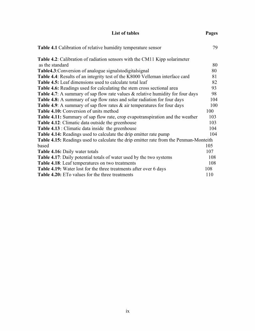
List of tables Pages
Table 4.1 Calibration of relative humidity temperature sensor 79
Table 4.2: Calibration of radiation sensors with the CM11 Kipp solarimeter as the standard 80 Table4.3:Conversion of analogue signalstodigitalsignal 80 Table 4.4: Results of an integrity test of the K8000 Velleman interface card 81 Table 4.5: Leaf dimensions used to calculate total leaf 82 Table 4.6: Readings used for calculating the stem cross sectional area 93 Table 4.7: A summary of sap flow rate values & relative humidity for four days 98 Table 4.8: A summary of sap flow rates and solar radiation for four days 104 Table 4.9: A summary of sap flow rates & air temperatures for four days 100 Table 4.10: Conversion of units method 100 Table 4.11: Summary of sap flow rate, crop evapotranspiration and the weather 103 Table 4.12: Climatic data outside the greenhouse 103 Table 4.13 : Climatic data inside the greenhouse 104 Table 4.14: Readings used to calculate the drip emitter rate pump 104 Table 4.15: Readings used to calculate the drip emitter rate from the Penman-Monteith based 105 Table 4.16: Daily water totals 107 Table 4.17: Daily potential totals of water used by the two systems 108 Table 4.18: Leaf temperatures on two treatments 108 Table 4.19: Water lost for the three treatments after over 6 days 108 Table 4.20: ETo values for the three treatments 110

x
List of annexes
Annex A: The irrigation control program …………………………………………. 126
Annex B: The data logger program for outside greenhouse weather……………… 130
Annex C: The data logger program for inside greenhouse weather…………… 133
Annex D: The Day of Year (Julian) calendar ……………………………………… 136

1
CHAPTER 1 BACKGROUND AND JUSTIFICATION
1.1 Introduction Agriculture is one of the mainstays of the Zimbabwean economy and accounts for 20% of
Gross Domestic Product (GDP) (Horticultural Promotion Council of Zimbabwe, 2000).
The country has experienced phenomenal growth in horticultural exports over the past
two decades and in 1999 alone, they trebled by volume and increased five-fold by value
(Horticultural Promotion Council of Zimbabwe, 2000). Water is a chief input in
horticulture that directly affects the quality and quantity of yield. Its management is
therefore of importance to the farmer. The increasing worldwide shortages of water and
costs of irrigation are leading to an emphasis on developing methods that minimize water
use and maximize the water use efficiency (Jones, 2004). Irrigation scheduling has
conventionally aimed to achieve an optimum water supply for productivity, with soil
water content being maintained close to field capacity. Estimation of evapotranspiration,
an indication of plant water use, is used to design irrigation schedules. Common
schedules are based on evaporation pan measurements (Pruitt,1966; Doorenbos and
Pruitt,1975), soil moisture measurements (Smith and Mullins, 2000; Dane and Topp,
2002) and meteorological measurements usually based on accumulated input solar
radiation and calculation of reference crop evapotranspiration (ETo) based on the
Penman Monteith equation.. These schedules have inherent flaws. Inadequate irrigation
tends to waste water, nutrients and energy, and may cause soil degradation by water-
logging and salinisation (Baille, 1994). In addition challenges of labour, and response

2
time to offset moisture stress continue to inhibit the correct supply of water. In order to
achieve higher levels of profitable and sustainable production, it is essential to modernize
existing irrigation systems to improve water management. Automation of irrigation
schedules holds a promise of efficiently optimizing the supply of water needed to satisfy
the requirements of crops.
Jones (2004) observed that many features of the plant’s physiology respond directly to
changes in water status in the plant tissues, whether in the roots or in other tissues, rather
than to changes in the bulk soil water content (or potential). As a result more precise
irrigation schedules can be achieved with plant stress sensing or the speaking plant
approach. To estimate plant water status, sensors like sap flow gauges (Granier,1987;
Cohen et al.,1981; Cermak and Kucera,1981) have proved to be practical in use and, in
most cases, are accurate to within 5% on a daily basis (Dugas,1990). Sap flow
measurements of transpiration using both steady state heat flux (Sakuratani, 1981; Baker
and van Bavel, 1987) and heat pulse technology (Cohen et al, 1981) remain a potential
method for automating irrigation control based on direct physical plant measurements.
Dendrometers that monitor the response of stem diameter to water stress (Huguet et al.,
1992) can also be employed.
1.2 Problem statement The use of such plant indicators, while being the ideal method for irrigation scheduling, is
still hampered by the relatively low knowledge of the dynamic nature of plant water
status and by the lack of suitable indicators, relative to established scheduling methods

3
based on atmospheric and soil observations. In addition, the practical application of the
researched theory in irrigation scheduling is very limited (Cohen, 2003; Garcıa-Orellana
et al., 2007).
1.2.1 Aim
This project seeks to design and implement a flexible plant based irrigation control with a
more precise schedule using plant based responses as the indicator for determining the
timing and amount of irrigation for greenhouse crops.
1.3 Objectives i. To monitor sap flow rates of greenhouse crops under different
conditions,
ii. To design an automated irrigation schedule based on
transpiration rates measured by sap flow gauges,
iii. To implement and compare this irrigation system with
traditionally existing methods that are based on meteorological
variables.
1.4 Expected benefits • Conservation of water and increased water use efficiency.
• Enhanced crop productivity/yield through applying requisite amounts of water.
• Reduced labour, energy consumption and input costs.
• Flexible and user friendly system
4
1.5 Thesis layout The project is made of five chapters. The first chapter deals with the introduction to the
project under which the background and justification are discussed. The chapter gives an
in-depth picture on the direction of the project and insight on the intended objectives.
The second chapter delves on the literature survey. This chapter reviews the theory on
irrigation methods and scheduling aspects, crop water requirements and
evapotranspiration estimation. It also sheds light on related topics to the project and
works that have been done in the past by other researchers. The third chapter focuses on
the materials and methodology. This chapter explains how the project was done or
executed and the materials or apparatus employed to achieve the intended objectives. The
location and geography of the area where the project was done are included in this
section. The fourth chapter entails the analysis of results and discussion. Statistical
interpretation using Microsoft Excel is done to give comprehensive scientific results. The
fifth chapter concentrates on the lessons learnt, conclusions and recommendations.

5
CHAPTER 2 LITERATURE REVIEW
2.0 Introduction The Zimbabwean horticultural export industry continues to experience phenomenal
growth since inception in the mid 1980s and is now the third largest agricultural
commodity after tobacco and livestock. In addition, horticulture is acknowledged as the
second largest foreign exchange earner after tobacco and accounts for approximately 3.5
< 4.5 % of GDP. Foreign exchange earnings have increased by an average of 30 % per
annum over the past ten years. The success of the industry has been based on free market
situation requiring considerable entrepreneurial flair from producers. Most exporters
employ agents who act on their behalf, and some growers access expertise in the form of
consultants.
Horticultural production and exports have been the fastest growing sector in the
Zimbabwean economy registering a growth rate in excess of 30 % per annum. In the last
fifteen years horticultural exports have grown from US$3.515 million in the season
1985/86 to US$139.518 million in 2000/1. Prospects for continued growth are
encouraging. Of significance is the fact that for all product groups, the most important
export destination is the European community, with 99 % of cut flowers, 89 % of
vegetables, herbs and spices, and 75 % of citrus.
The performance and success of horticulture is hinged on accurate water supplies
assuming other farming management practices are in place. The supply of the required

6
water to the plant is of prime importance for its growth and economic production,
especially in greenhouses, where irrigation is the only source of water for the plant. In
this chapter the water requirements of greenhouse crops, physiological and/ or
morphological effects of water on greenhouse crops, greenhouse microclimate, different
irrigation methods and schedules, the automation of schedules, and the contemporary
technologies being employed to automate schedules will be discussed.
2.1 Water requirements of greenhouse crops Water is an essential plant component being a major constituent of plant cells, and
ranging from about 10% of fresh weight in many dried seeds to more than 95% in some
fruits and young leaves. Many of the morphological and physiological characteristics of
land plants are adaptations permitting life on and by maintaining an adequate internal
water status in spite of the typically rather dry aerial environment. The unique properties
of water (Slayter 1967, Einsenberg & Kauzmann 1969, and Nobel 1991) form the basis
of much environmental physiology. For examples it is a liquid at normal temperatures
and is a strong solvent, thus providing a good medium for biochemical reactions and for
transport (both short-distance diffusion and long-distance movement in the xylem and
phloem). Water is also involved as a reactant in processes such as photosynthesis and
hydrolysis, while its thermal properties are important in temperature regulation and its
compressibility is important in support and growth.
2.1.1 The greenhouse water cycle
The main process involving the fate of water in the greenhouse, and hence the water
requirements of crops, is evapotranspiration, a process that is driven by a constant inflow

7
of energy. In fact, the water balance is intimately and reciprocally related to the cycle and
balance of energy (Boulard and Baille, 1993), since the state and content of water in the
soil and its vegetative cover is affected by, and in turn, affects, the way the energy fluxes
reaching the soil is partitioned and utilized. Control of the soil-plant-atmosphere system
must therefore be based on simultaneous consideration of both the water and the energy
balance. Two components of the greenhouse water cycle are important to measure and to
control. The first one is the soil component (or artificial substrate), where the water
balance is an account of all quantities of water added to, subtracted from and stored
within the root zone during a given period of time.
[Storage]=[Gains]-[Losses] (2.0)
For greenhouses, this general statement can be written as follows:
DS=W-(DR+Es+TR) (2.1)
where DS is the quantity of water stored in the substrate, DR is the drainage, Es is the soil
evaporation and TR the actual transpiration of the crop. The last two variables are
difficult to separate, and are generally lumped together and termed ‘evapotranspiration’
(ET=Es+TR).It is still difficult to measure in practice the soil water balance. Often, the
larger component of the losses side and the most difficult to measure directly, is the
evapotranspiration, ET. To obtain the irrigation requirement, W, from the water balance
equation (2.1), we must have accurate measurements of the other terms of the equation.

8
For long period, the change in water content of the root zone is likely to be small in
relation to the total water balance. Soil evaporation is negligible if localized irrigation is
practiced in soil less cultures or if the soil or substrate is covered by a mulch or plastic
cover. If we neglect Es, W is approximately equal to the sum of TR plus the drainage,
DR. TR is equal to the water uptake by the plant, A, minus the water stored in the plant
organs, DWp. Then:
W=TR+D=A-DWp-DR (2.2)
Figure 2.1: The water balance of a cropped soil (Allen et al., 1999)

9
2.1.2. Variation in water status in relation to greenhouse climatic factors
2.1.2.1Dynamic behavior of leaf water potential
The diurnal variation in leaf water potential (Ψleaf) closely reflects the diurnal variation in
transpiration and in its main driving forces, radiation and vapour pressure deficit (VPD),
in field grown as well as in greenhouse grown tomato. A simple model for Ψleaf is the
steady state equation using the Ohm’s Law analogue(equation 2.3)
Ψleaf = Ψsoil - E x Rsoil-plant (2.3)
which does not include any effects of variable hydraulic resistance, capacitance,
coupled solute flow or volume for growth. Effects of the greenhouse climate act upon
transpiration rate (TR) and Ψsoil, while a factor like temperature of the root environment
might affect Rsoil-plant. When E diminishes, Ψleaf will reach a maximum value, equal to Ψ
of the root environment. In growing tissue, however, a small Ψ gradient will be
maintained (Cosgrove, 1986). In the field the predawn Ψplant commonly approachesΨsoil.
2.2 The microclimate of crops under a greenhouse The changes in wind speed and turbulence that occur as a result of windbreaks affect the
microclimate of the sheltered zone.
2.2.1 Radiation balance
Solar and net radiation may be significantly reduced in the areas shaded by windbreaks.
This effect has not been found to be of major importance in north-south oriented
windbreak systems, since only small areas are shaded during the course of the day,
especially during the growing season when the sun is high. On a full day basis, the
difference in radiation balance between areas near and areas remote from the barrier may

10
be entirely negligible. This follows; since an area shaded in the morning by a windbreak
to the east will receive some additional radiation by reflection from the windbreak to the
east will receive some additional radiation by reflection from the windbreak in the
afternoon. East-west oriented windbreaks, on the other hand, may have a greater effect.
Areas to the north, particularly during seasons when the sun is low, will be shaded for
long periods. Areas to the south will be subject to reflection off the windbreak throughout
the day. Shading depends, of course, on the height of the barrier, on latitude, season, and
time of day. While severe shading may suppress photosynthesis and dry matter
production, this effect can be offset by reduced evapotranspiration in the shaded zone.
2.2.2 Air temperature and humidity
It is usually observed in clear weather that daytime air temperatures are greater in shelter
than in open fields. This is due, apparently, to the reduction of turbulent mixing of cold
and warm air and the consequent reduction in the removal of sensible heat generated at
the plant or soil surface. If evaporation is also suppressed in shelter, additional energy is
available for sensible heat generation as well. When turbulent mixing is reduced, the
aerial resistance ra increases and the temperature gradients are intensified. Temperature
inversions normally develop at night in both sheltered and unsheltered areas; then the
plant and soil surfaces become the sink for sensible heat. Windiness mixes the nocturnal
inversion layer. The reduction of windiness and effectiveness of turbulent mixing in
shelter means that temperature inversions will normally be more intense there. Unless
total calm prevails, the air will generally be colder at night in shelter than in open fields.
The reduction of cooling near the windbreak could have been due to radiative exchange

11
with the trees. Probably the increased vapour content of the air in that zone may have
reduced the rate of radiational cooling, as well. Humidity and vapour pressure gradients
are also increased in shelter. Transpired and evaporated water vapour is not as readily
transported away from the source, the evaporating surface, as in an unsheltered field.
Vapour pressure remains higher in shelter throughout the night as well, since the surface
usually remains the source of vapour, except during periods of dew deposition. Such
intensified temperature and vapour pressure gradients in shelter have been observed
under a wide range of climatic conditions with many types of vegetative and constructed
barriers used to shelter many different types of crops studied. Despite the increased
temperature the relative humidity is generally greater by day in shelter i.e. shelter
prevents the escape of air molecules to the atmosphere.. The difference in relative
humidity is generally greater by day in shelter. The difference in relative humidity
between open and shelter is greater still at night because of the lower air temperatures in
shelter. It is also important to recognize that the microclimate differences that develop in
shelter vary with distance from the wind break, with weather conditions and with time of
day.
2.2.3 Gradients and profiles
The changes in microclimatic conditions occur at more than one level above and within
the sheltered crop. Since turbulent mixing is affected it is reasonable to expect that
gradients of temperature, humidity, carbon dioxide, will also be changed.

12
2.3 Plant Physiology responses to shelter Microclimate differences develop in shelter and the shelter microclimate influences crop
growth and production. Often plants in shelter show more rapid vegetative growth and
increase in size because of high temperatures that favour growth. This is manifested by
greater total Leaf Area Index (LAI) and plant height. Plant growth and performance in
shelter may also be favoured because the use of windbreaks reduces the incidence of
mechanical injuries such as are caused by ‘sandblasting’. Mechanical injuries may cause
loss of production by defoliation, that is, loss of viable tissue, or by imposing short, high-
intensity moisture stress on the injured plant. Both factors may combine to reduce
productivity. Recent studies suggest, however, that the major influence of shelter on plant
behaviour is due to a greater turgidity and lower stomatal resistance in the sheltered
plants, especially during periods of water stress or strong evaporative demand. Wind
tunnel studies show that transpiration increases with increasing wind speed. On the other
hand, found, in a greenhouse study, that water use by beans and overall plant growth
decreased when winds increased above 1ms-1.
2.4 Evapotranspiration Evapotranspiration of a crop indicates the rate at which water is lost from the crop to the
atmosphere as transpired and evaporated water. Weather parameters, crop characteristics,
management and environmental aspects are factors affecting evaporation and
transpiration. Measurements of water loss are therefore important to the farmer to know
how much water needs to be replenished to enhance a healthy crop growth.
13
2.5.1 Weather parameters
Crop evapotranspiration is influenced by weather parameters like radiation, air
temperature, humidity and wind speed. The evaporation power of the atmosphere is
expressed by the reference crop evapotranspiration, ETo. The reference crop
evapotranspiration represents the evapotranspiration from a standardized vegetated
surface.
2.5.2 Crop factors
The crop type, variety and development stage should be considered when assessing the
evapotranspiration from crops grown in large, well managed fields. Differences in
resistance to transpiration, crop height, crop roughness, reflection, ground cover and crop
rooting characteristics result in different evapotranspiration (ET) levels in different types
of crops under identical environmental conditions. Crop evapotranspiration under
standard conditions (ETc) refers to the evaporating demand from crops that are grown in
large fields under optimum soil water, excellent management and environmental
conditions, and achieve full production under the given climatic conditions.
2.5.3 Management and environmental conditions
Factors such as soil salinity, poor land fertility, limited application of fertilizers, the
presence of hard or impenetrable soil horizons, the absence of control of diseases and
pests and poor soil management may limit the crop development and reduce the
evapotranspiration. Other factors to be considered when assessing ET are ground cover,
plant density and the soil water content. The effect of soil water content on ET is
conditioned primarily by the magnitude of the water deficit and the type of soil. On the

14
other hand, too much water will result in waterlogging which might damage the root and
limit root water uptake by inhibiting respiration.
2.5.4 Reference crop evapotranspiration (ETo)
The evapotranspiration rate from a reference surface, not short of water, is called the
reference crop evapotranspiration or reference evapotranspiration and is denoted as ETo.
The reference surface is a hypothetical grass reference crop with specific characteristics.
The concept of the reference evapotranspiration was introduced to study the evaporative
demand of the atmosphere independently of crop type, crop development and
management practices. As water is abundantly available at the reference evapotranspiring
surface, soil factors do not affect ET. Relating ET to a specific surface provides a
reference to which ET from other surfaces can be related. It obviates the need to define a
separate ET level for each crop and stage of growth. ETo values measured or calculated at
different locations or in different seasons are comparable as they refer to the ET from the
same reference surface. The only factors affecting ETo are climatic parameters.
Consequently, ETo is a climatic parameter and can be computed from weather data. ETo
expresses the evaporative demand of the atmosphere at a specific location and time of the
year and does not consider the crop characteristics and soil factors. The FAO Penman-
Monteith method is recommended as the sole method for determining ETo. The method
has been selected because it closely approximates grass ETo at the location evaluated, is
physically based, and explicitly incorporates both physiological and aerodynamic
parameters.

15
2.6 Irrigation scheduling techniques in greenhouses
Estimation of crop water requirements or the response of plants to water stress can be
indicated by the following methods which in turn are used to design irrigation schedules.
2.6.1 Meteorological based
2.6.1.1 ET computed from meteorological data
Owing to the difficulty of obtaining accurate field measurements, ET is commonly
computed from weather data. A large number of empirical or semi-empirical equations
have been developed for assessing crop or reference crop evapotranspiration from
meteorological data. The FAO Penman-Monteith method is now recommended as the
standard method for the definition and computation of the reference evapotranspiration,
ETo. The ET from crop surfaces under standard conditions is determined by crop
coefficients (Kc) that relate ETc to ETo. The ET from crop surfaces under on-standard is
adjusted by a water stress coefficient (Ks) and/or by modifying the crop coefficient.
2.6.1.2. Determination of ETo using FAO Penman-Monteith method
The FAO Penman-Monteith method is maintained as the sole standard method for the
computation of ETo from meteorological data. From the original Penman-Monteith
equation and the equations of the aerodynamic and canopy resistance, the FAO Penman-
Monteith equation ETo is as follows
ETo = )234.01(
)(2273
900)(408.0
u
aeseuT
GRn
++∆
−+
+−∆
γ
γ (2.6)

16
Where ETo reference evapotranspiration [mm day-1]
Rn net radiation at the crop surface [MJm-2day-1]
G soil heat flux density [MJm-2day-1]
T air temperature at 2m height [oC]
u2 windspeed at 2m height [m s-1]
es saturation vapour pressure [kPa]
ea actual vapour pressure [kPa]
es-ea saturation vapour pressure deficit [kPa],
∆ slope vapour pressure curve[kPaoC-1]
The FAO Penman-Monteith equation determines the evapotranspiration from the
hypothetical grass reference surface and provides a standard to which evapotranspiration
in different periods of the year or in other regions can be compared and to which the
evapotranspiration from other crops can be related.
Figure 2.2: A simplified representation of the (bulk) surface and aerodynamic resistances for water vapour flow (Allen et al., 1999)

17
The resistance nomenclature distinguishes between aerodynamic resistance and surface
resistance factors. The surface resistance parameters are often combined into one
parameter, the ‘bulk’ surface resistance parameter which operates in series with the
aerodynamic resistance, rs, describes the resistance of vapour flow through stomata
openings, total leaf area and soil surface. The aerodynamic resistance, ra, describes the
resistance from the vegetation upward and involves friction from air flowing over
vegetative surfaces. Although the exchange process in a vegetation layer is too complex
to be fully described by the two resistance factors, good correlations can be obtained
between measured and calculated evapotranspiration rates, especially for a uniform grass
reference surface. The Penman-Monteith form of the combination equation is:
λE = )1(
)()(
a
s
a
aspa
rr
ree
CGRn
++∆
−+−∆
γ
ρ (2.7)
Where Rn is the net radiation, G is the soil heat flux, (es-ea) represents the vapour pressure
deficit of the air, ρa is the mean air density at constant pressure, cp is the specific heat of
the air, ∆ represents the slope of the saturation vapour pressure temperature relationship,
γ is the psychrometric constant, and rs and ra are the (bulk) surface and aerodynamic
resistances.
2.6.1.3 Solar radiation based methods
The main role of solar of solar radiation in determining the evapotranspiration in a
greenhouse (Morris et al., 1957, Lake et al., 1966), showing a strong correlation between
daily evapotranspiration and solar irradiance. This constatation has given raise to the so
called ‘solar radiation’ method or ‘solarimeter’ method, based on a simple relationship

18
giving the reference evapotranspiration under greenhouse if the outside global radiation,
RGo and the greenhouse transmission, t, are known:
ETo = K tRGo/2.5 (2.11)
(ETo in mm day-1, RGo inMJm-2 day-1)
Where K is an empirical coefficient, whose value is about 0.6 to 0.7
Crop coefficient based on this reference ET has been proposed for the main greenhouse
species (Laberche et al 1977, De Graaf and van der Ende, 1981).
2.6.1.4 ET computed from pan evaporation
ETo can also be estimated from the evaporation loss from a water surface.
Evaporation from an open water surface provides an index of the integrated effect of
radiation, air temperature, air humidity and wind on evapotranspiration. However,
differences in the water and cropped surface produce significant differences in the water
loss from an open water surface and the crop. The pan has proved its practical value and
has been used successful to estimate reference evapotranspiration by observing the
evaporation loss from a water surface and applying empirical coefficients to relate pan
evaporation to ETo.

19
Figure 2.3: Showing surfaces used to compute evapotranspiration(Allen et al., 1999) Pans of many shapes and sizes have been used to measure free water evaporation. Pans
are inexpensive, relatively easy to maintain and simple to operate. However, care must be
taken in relating evaporation from pans to actual ET, especially in arid climates. Because
of the smaller aerodynamic roughness of water surfaces relative to vegetative surfaces,
the former will extract less sensible heat energy from the passing air. Thus pans may at
times, show less evaporation than ET from vegetation (Rosenberg, 1983).
Figure 2.4: A Class A evaporation pan (Allen et al., 1999)

20
2.6.1.5 Problems related to ET estimation of greenhouse crops
The problem encountered in greenhouse crop ET estimation is that inside microclimate is
affected by the outside climate, the type of greenhouse, the climate control strategy and
the feedback between the crop and the inside microclimate. The concept of potential
evapotranspiration for greenhouse crop often leads to misleading interpretations. Many
authors have intended to propose calculation methods based on outside weather variables,
eluding the fact that the outside climate is often poorly coupled to the internal
microclimate. The concept of reference evapotranspiration is also somewhat difficult and
delicate to be applied to greenhouse crops water requirements, because the two
“reference” crops (grass, alfalfa) are not commonly grown in greenhouse production. The
data from pan evaporimeters are affected by the spatial heterogeneity of greenhouse
climate and the proximity and continuous evolution of the vegetation.
Another problem is inherent to the crop coefficient, Kc. Stanghellini et al.(1990)
developed an analytical formulation of Kc, expressed as the ratio of the theoretical crop
transpiration assuming maximal crop conductance to a given reference evapotranspiration
. They showed for greenhouse tomato crops that this coefficient is a function of crop
parameters, leaf area and prevailing weather, and that it is a coincidence that the crop
coefficient in greenhouse crops was almost constant in its seasonal trend, due to the
combination of two opposite effects. All these considerations suggest that the use of
physically-based formulations of ET that take into account both crop parameters (such as
maximal conductance) and the prevailing climatic regime in the greenhouse seem to be
preferable to other empirical methods. However, these specific crop parameters are not

21
available for all the main species grown under greenhouses. That is why the classical
methods based on a given reference ET and crop coefficient are still largely used for
estimating water requirements of greenhouse crop, although their shortcomings are now
well recognized.
2.6.2 Soil Moisture Based Methods
2.6.2.1 Available water capacity and plant available water
The available water capacity (AWC) defines the amount of water in a soil that is
nominally available for plant growth. The upper limit is set by the field capacity (FC) and
the lower limit as the value of θ at which plants lose turgor and wilt, that is, the
permanent wilting point (PWP). In some extensive cropping systems, such as for
vegetables, orchards and vineyards, the concept of readily available water (RAW) is also
used. RAW is defined as the amount of water held between FC and matric potential (ψm)
values of -40 to -60 kPa, depending on the age of the plants and the soil texture.
2.6.2.1 .1 Lysimetry
Lysimeters are large blocks of soil isolated from, but as identical as possible with,
surrounding soils. According to Pelton (1961), lysimeters were first used to study the
percolation of water through soils. It was not until the twentieth century that modification
in lysimeter design was made to permit the study of evapotranspiration. Different types of
lysimeters range widely in the accuracy with which changes in the soil water content are
detected. The most accurate lysimeters can detect losses as small as 0.01 mm of water
and can be used to accurately detect ET rates over time periods shorter than 1h

22
(measurements over 5-10 min periods have been reported). Other lysimeters are only
sensitive enough to detect changes that occur over a day or longer.
Lysimeters provide the only direct measure of water flux from a vegetative surface. As
such, they provide a standard against which other methods can be tested and calibrated.
To provide reliable measurement of ET, lysimeters should meet the following criteria
(Pelton, 1961):
1. They should be constructed so that moisture relationships inside the lysimeter
correspond closely to those of soils under natural conditions.
2. The lysimeters should be sufficiently deep to extend well below the plant root
zone or should use a tensioning device at the bottom of the soil column to
maintain moisture at or near the same level as surrounding areas.
3. Lysimeters should be managed in exactly the same manner as the surrounding
area.
4. The ratio of the wall surface area to the enclosed lysimeter area should be small to
avoid small-scale advection from the uncropped surface.
5. Common types of lysimeters are
• potential evapotranspirometers
• floating lysimeters
• weighing lysimeters
2.6.2.1.2 Gravimetry
Soil wetness is characterized by the amount of water held in a certain mass or volume
of soil; that is:gravimetric water content (θg), measured by drying the soil to a
constant weight at a temperature of 105oC. θg is then calculated from

23
θg= mass of water / mass of oven dry soil (2.23)
θg (units of g H2O/g oven dry soil) is often expressed as a percentage by multiplying
by 100. Structural water, which is water of crystallization held in soil minerals, is not
driven off at 105oC and is not measured as soil water.
2.6.3 Plant based methods
2.6.3.1 Sap flow gauges
2.6.3.1.1 Stem heat balance (SHB) theory
The SHB method requires a steady state and a constant energy input from the heater strip
inside the gauge body. Therefore the stem section must be insulated from changes in the
environment. For the same reason, the gauge time constant is limited from five minutes to
an hour, depending on the flow rate and the stem size. The Dynamax loggers have a
power down mode so that power is preserved from overheating. During the power down
mode and at the transitions to power on, the sap flow is not computed to maintain the
accumulated flow accurately during this unbalanced transition.
Figure 2.5: Stem Gauge Schematic (van Bavel, 1987)

24
Figure 2.5 shows a stem section and the possible components of heat flux, assuming no
heat storage. The heater surrounds the stem under the stem under test and is powered by a
DC supply with a fixed amount of heat; Qh. Qh is the equivalent to the power input to the
stem from the heater, Pin. Qr is the radial heat conducted through the gauge to the
ambient. Qv, the vertical or axial heat conduction through the stem has two components,
Qu and Qd. By measuring Pin, Qu,Qd and Qr, the remainder, Qf can be calculated. Qf is
the heat convection carried by the sap. After dividing by the specific heat of water and
the sap temperature increase, the heat flux is converted directly to mass flow rate.
Energy balance equations:
The energy balance is expressed as:
Pin =Qr +QV+Qf (W)……………………. (2.12)
Pin =V2/R from Ohms law…………. (2.13)
Fourier’s law describes the vertical conduction components:
Qv = Qu+Qd
Where Qu=KstAdTu/dX………………………….(2.14)
Qd= KstAdTd/dX……………………………………..(2.15)
Where Kst is the thermal conductivity of the stem (W/m*K); A is the stem cross sectional
area (m2); the temperature gradients are dTu/dX (K/m) and dTd/dX; dX is the spacing
between thermocouple junctions (m).One pair of thermocouples is above the heater and
one pair is below the heater as shown on the schematic in figure 2.6.

25
Figure 2.6: Dynagage schematic diagram (van Bavel, 1987) There are two differentially wired thermocouples both measuring the rise in sap
temperature. Channel AH measures the difference in temperature A-Ha (mV). Channel
BH measures the difference in temperature B-Hb (mV). By subtraction of these two
signals:
BH-AH =(B-Hb)-(A-Ha) =(B-A) +(Ha-Hb) (mV)
The result yields the two components of axial heat conduction out of the stem section,
Qu and Qd. Since the distance, dX, separating the upper TC pair and lower TC pair are
fixed by design for each particular gauge to the same value; the components of Qv are
combined with a common denominator:
Qv =KstA(BH-AH)/ dX*0.040 mV/C
The factor 0.040mV/C converts the thermocouple differential signals to degrees C. Kst
values are given for varying stem conductivity: 0.42 W m-1K-1 (woody stem), 0.54 W m-
1K-1 (herbaceous), and 0.28 W m-1K-1 (hollow).

26
2.6.3.1.2 Sap thermodynamics
After solving equation (2.12) for Qf, the flow rate per unit of time is calculated from the
equation for flow as described by Sakuratani (1981) and Baker-Van Bavel (1987). This
equation takes the residual of the energy balance in Watts, and converts it to a flow rate
by dividing by the temperature of the sap and the heat capacity of water. Water is 99% of
the sap content and it is safe to assume the heat capacity, Cp, is constant to all stems. It is
understood that a watt being 1 joule/second, will be converted to a flow rate when
divided by 4.186 joules/ gram-deg C, and is divided by the temperature increase in C.
F = (Pin-Qv-Qr)/ Cp*dT (g/s)………. (2.16)
In equation 2.16 the radial heat loss is computed in by:
Qr = Ksh * CH………………………. (2.17)
Ksh is the thermal conductance constant for a particular gauge. Cp is the specific heat of
water (4.186 J/g*C), and dT is the temperature increase of the sap. The temperature
increase of the sap, dT is measured in mV by averaging the AH and BH signals, and then
converted to degrees C by dividing by the thermocouples temperature conversion
constant as follows:
dT = CmVmVBHAH
/040.0)(2/)( +
2.6.3.1.3 Ksh calculation
The sheath conductance is calculated when the user establishes a no-flow condition. The
ksh algorithm is derived from flow calculation steps, and it is computed every scan
period, then averaged every 30 minutes. Although the Ksh calculation is computed during
the day, and may have high values at high flow and negative values when Qr heat is
negative (inward heat flux), Ksh has no meaning except when the flow is zero. The

27
condition for Ksh is determined by solving equation (2.17) when setting Qf =0 as
follows:
Pin = Qr+Qv
And Qr =Ksh (CH)= Pin - Qv
So after computing Pin and Qv,
Ksh = (Pin - Qv)/(CH) (W/mV)……………….(2.18)
2.6.3.2 The trunk sector heat balance method
The trunk sector heat balance method of sap flow measurement is intended for use on tree
trunks with diameters larger than 120 mm. like the stem heat balance method it is based
on the principle that sap flow rates can be determined from the heat balance of heated
stem tissue. However, in the trunk sector heat balance method, heat is applied internally
to only a segment of the trunk, rather than superficially to the entire circumference. The
measurement system can be purchased commercially.
2.6.3.2.1 Theory of operation
An alternating current (1.5 kHz) converted from a 12V Dc supply, is applied to the five
electrodes embedded in the tree trunk, so that the electrical impedance of the woody
tissue causes the four segments of sapwood bounded by electrodes to be heated. The use
of an AC supply ensures that electrochemical effects in the tissue are avoided (Kucera et
al., 1977). The trunk is insulated and shielded from radiation, so that the heat balance of
the trunk sector is (Cermak et al., 1973)
P = qv+qr+ql+qf (2.19)

28
Here P is the electrical power dissipated as heat in the trunk sector, qv is heat lost
vertically by conduction, qr is heat lost radially inwards to the non-conducting heartwood
and outwards to the cambium and bark, ql is the heat lost laterally into neighbouring
sapwood by conduction; and qf is heat loss by convection in the moving sap stream. The
mass flow rate of sap is determined from the value of qr for the two segments at the
centre of the heated zone, which is evaluated by accounting for all other terms in equation
2.18.
Two versions of the instrument have been used (Cermak et al., 1984); in the first, which
is the version available commercially, P is constant (Cermak et al., 1973), whereas in the
second, a constant value of ∆T is maintained by automatic regulation of the power supply
(Kucera et al., 1977). In both systems, P is determined by measurement of the potential
drop across the electrodes and the current supplied (Cermak et al., 1976), while ql is
assumed to be negligible because ‘active thermal insulation’ of the two central segments.
Lateral heat losses are eliminated from the heat balance of these segments because the
adjoining segments are heated to the same temperature, so that lateral temperature
gradients do not occur and lateral heat losses by conduction are avoided (Cermak et al.,
1973). The remaining heat losses by conduction, qr and qr, are accounted for together. In
the constant power, qv+qr is found from
qv+qr = Kvt∆T (2.19)

29
where Kvt is a thermal conductance coefficient which must be evaluated during periods
when there is no sap flow. The value of Kvt accounts for the thermal conductivity of the
tissue and insulation materials surrounding the heated zone, as well as the distance
between thermocouples, so it must be evaluated for each new installation. From equation
2.18 qv+qr when sap flow is zero (assuming ql =0), so that Kvr can be found from
Kvr = Po / ∆To (2.20)
where Po and ∆To are values of P and ∆T measured when sap flow is zero. For the
constant temperature system, ∆T is constant and so qv+qr can be assumed to be constant,
with a value of Po.
With all other components of the heat balance of the trunk sector accounted for, qr is
calculated by difference using equation 6 and converted to rate of mass flow through the
central segmentsof the heated zone (Fm,c) by
Fm,c = qf / cs∆T (2.21)
where cs is the specific heat capacity of sap, which is assumed equal to that of water, Fm,c
is then multiplied by the ratio of the width of the two central segments to the entire stem
circumference to estimate sap flow for the whole tree (Cermak et al., 1976). Where there
is substantial variation should be made at more than one location on the circumference of
the trunk in order to reduce errors in estimates of flow for the whole tree (Cermak et al.,
1995).

30
2.6.3.3 Heat-pulse method
With the heat method, rates of sap flow are measured by determining the velocity of a
short pulse of heat carried by the moving sap stream, rather than the heat balance of a
heated stem. The method is suitable only for use on woody stems. Heater and sensor
probes must be installed by drilling holes into the sapwood, so that its use is limited to
stems that are large enough to accommodate these, but not so large that the full depth of
sapwood cannot be accessed; generally, it can be used on stems with diameters larger
than about 30 mm. Two heat-pulse systems are commercially available.
2.6.3.3.1 Theory of operation
The heat pulse technique is based on the compensation principle; the velocity of sap
ascending a stem is determined by compensation of the measured velocity of a heat pulse
for the dissipation of heat by conduction through the matrix of wood fibres, water and gas
within the stem (for a historical view, Swanson,1994) with modern instrumentation, this
is accomplished by deploying the sensor probes at unequal distance upstream and
downstream for the heater probe, with the upstream sensor placed nearer to the heater
than the downstream sensor (Swanson and Whitfield, 1981; Swanson, 1994).
Immediately after release of a pulse of heat of 1-2s duration, the temperature becomes
higher at the closer, upstream sensor than at the downstream sensor because of
conduction; but heat carried by the moving sap then quickly warms the downstream
sensor, so that the temperature of the two sensors is again equal after a time (te) in the
order of 60s. This is the time required for convection in the moving sap stream to move
the peak of the heat pulse from the heater to the point midway between the two
31
temperature sensors, so that te decreases as sap velocity increases. The velocity of the
heat pulse (vh) is thus given by Swanson and Whitfield, 1981.
vh= (xd-xu)/ 2te (2.22)
2.6.3.4 Leaf thickness
A number of instruments are available for the routine monitoring of leaf thickness, which
is known to decrease as turgidity decreases. Approaches include direct measurement
using linear displacement transducers (e.g. LVDTs [Burquez, 1987] or capacitance
sensors or through measurements of leaf ‘superficial density’ using β-ray attenuation
(Jones, 1973). Unfortunately, leaf thickness is frequently even less sensitive to changes in
water status than is leaf water content because, especially with younger leaves, a fraction
of leaf shrinkage is often in the plane of the leaves rather than in the direction of the
sensor (Jones, 1973).
2.6.3.5 Stem and fruit diameter
Stem and fruit diameter fluctuate diurnally in response to changes in water content, and
so suffer from many of the same disadvantages as other water status measures. The
diurnal dynamics of changes in diameter, especially of fruits, have been used to derive
rather more sensitive indicators of irrigation need, where the magnitude of daily
shrinkage has been used to indicate water status, and comparisons of diameters at the
same time on succeeding days give a measure of growth rate (Huguet et al., 1992; Li and
Huguet, 1990; Jones, 1985).Although changes in growth rate provide a particularly
sensitive measure of plant water stress, such daily measurements are not particularly
useful for the control of high frequency irrigation systems. Several workers have

32
achieved promising results for low frequency irrigation scheduling by the use of
maximum daily shrinkage (MDS). For example, Fereres and Goldhamer (2003) showed
that MDS was a more promising approach for automated irrigation scheduling than was
the use of stem water potential for almond tres, while differences in maximum trunk
diameter were also found to be particularly useful in olive (Moriana and Fereres, 2002).
The use of such dendrometry or micromorphometric technique has been developed into a
number of successful commercial irrigation scheduling systems (e.g. Pepista 4000’, Delta
International, Montfavet, France); these are usually applied to the study of stem diameter
changes. Selles and Berger (1990) reported that variations in trunk diameter or stem
water potential were more sensitive as indicators of irrigation need than was the variation
in fruit diameter.
2.6.3.6 γ -ray attenuation
A related approach to the study of changes in stem water content was the use of γ – ray
attenuation (Brough et al., 1986). Although this was shown to be very sensitive, safety
considerations and cost have largely limited the further application of this approach.
2.7 Different irrigation methods Various methods of irrigation are used by farmers depending on water availability, the
type of irrigated crop and the financial investment the grower is intending to make. A
thorough knowledge regarding the irrigation techniques available can help give
information on the different types of deficit irrigation.

33
2.7 .1 Drip irrigation
While drip irrigation may be the most expensive method of irrigation, it is also the most advanced and efficient method in respect to effective water use. Usually used to irrigate fruits and vegetables, this system consists of perforated pipes that are placed by rows of crops or buried along their root lines and emit water directly onto the crops that need it. As a result, evaporation is drastically reduced and 25% irrigation water is conserved in comparison to flood irrigation. Drip irrigation also allows the grower to customize an irrigation program most beneficial to each crop. Water high in salts should be filtered before use since they may clog the emitters and create a local buildup of high salinity soil around the plants.
2.7 .4 Spray irrigation
The more modern spray irrigation in all its various forms is a more expensive type of
irrigation, requiring more complex machinery than flood irrigation, but it utilizes water
more efficiently, reducing the amount of water needed to irrigate a field. Even more
water is lost through evaporation in spray irrigation compared to flood irrigation and
plant diseases due to excess moisture can occur at overwatering. In spray irrigation
systems, a long hose is set to a water source on one side and on the side reaching the
field, water is released through spray guns.
The center-pivot system is an efficient way to irrigate a large field with minimum
machinery. This system is built of many triangular metal frames on wheels that hold the
central hose above the field. The hose transports water from a pump at the center of the
system and water is sprayed through sprinklers along the tube. The whole structure
circulates the field spraying water, with the water source as the center of the circle. The
disadvantages of this method, and other types of traditional spray irrigation, are the
electric motors needed to help the system roll in a circle and the large amounts of water

34
(about 35%) that evaporate or get blown away by winds before they even reach the
ground.
The Low Energy Precision Application (LEPA) center pivot system is a more efficient
irrigation method than the conventional pivot system, boosting the irrigation efficiency
from about 60% to more than 90%. This rise in effectiveness is also due to the decline in
the electricity usage, but mostly because the water is applied directly onto the crops and
not sprayed out into the air. This system also consists of a central hose, but instead of
high power sprinklers, pipes hang from the central hose and attached to the bottom of
each pipe, very close to the ground, is a nozzle that sprays water directly onto the crops.
This way , less water is lost through evaporation compared to traditional spray irrigation-
more than 90% of the water applied is used by the crop and less electricity is required.
2.8 Automation of irrigation controls The most widespread use of automated irrigation scheduling systems is in the intensive
horticultural, and especially the protected cropping, sector (Jones 2004). In general, the
automated systems in common use are based on simple automated timer operation, or in
some cases the signal is provided by soil moisture sensors. For timer-based operation
many systems simply aim to provide excess water to runoff at intervals (e.g. flood-beds
or capillary matting systems), although some at least attempt to limit water application by
only applying enough to replenish evaporative losses (often calculated from measured
pan evaporation; Allen et al., 1999). Much greater sophistication is required if an
objective is to improve the overall irrigation water use efficiency or to apply an RDI
(regulated deficit irrigation) system. Most of the remaining automated systems currently

35
in operation base control on soil moisture sensing; at least this approach has the potential
for greater precision and improved water use efficiency (Jones, 2004).
The use of expert systems (Plant et al., 1992) which integrate data from several sources
appears to have great potential for combining inputs from thermal or other crop response
sensors and environmental data for a water budget calculation to derive a robust irrigation
schedule. Among the various plant-based sensors that have been incorporated into
irrigation control are stem diameter gauges (Huguet et al., 1992), sap-flow sensors
(Schmidt and Exarchou, 2000) and acoustic emission sensors (Yang et al., 2003) though
there has been most interest in the application of thermal sensors. For example Kacira
and colleagues (Kacira and Ling, 2001; Kacira et al., 2002 have developed and tested on
a small scale automated irrigation controller based on thermal sensing of plant stress.
Similar approaches have been applied in the field: for example, Evanset al.(2001) and
Sadler et al.(2202) mounted an array of 26 infrared thermometer (IRTs) on a centre pivot
irrigation system which they used to monitor irrigation efficiency, but had not developed
the system to a stage where it could be used for fully automated control. Coloaizzi et al.
(2003) have tested another system that includes thermal sensing of canopy temperature
on a large linear move irrigator (where the irrigator moves across the field). In another
approach to the use of canopy temperature that makes use of the thermal kinetic window,
Upchurch et al. (1990) and Mahan et al. (2000) have developed a ‘biologically identified
optimal temperature interactive console’ for the control of trickle and other irrigation
systems based on canopy temperature measurements. In this direct control system,
irrigation is applied as canopy temperature exceeds a crop-specific optimum.

36
2.8.1 Irrigation control systems
In recent years, a variety of sophisticated features has been incorporated into residential
irrigation controllers. A controller is an integral part of an irrigation system. It is an
essential tool to apply water in the necessary quantity and at the right time to sustain
agricultural production and to achieve high levels of efficiency in water, energy and
chemical uses. An irrigation controller is responsible for selectively turning on and off a
set of sprinkler valve stations. When properly utilized some of these features can
contribute to an irrigation system that makes more efficient use of the available water
resource. An irrigation controller is a device used to control, electrically or otherwise,
operated valves, which control the flow of water to sprinkler heads and drip lines in an
irrigation system. A single irrigation valve typically controls the flow of water to a
specific area of a landscape. A computer-based control system consists of a combination
of hardware and software that acts as a supervisor with the purpose of managing
irrigation and other related practices such as fertigation and maintenance. This is done by
the use of a closed control loop. A closed control loop performs the following tasks 1)
monitoring the state variables, 2) comparing the state variables with their desired or target
state, 3) deciding what actions are necessary to change the state of the system, and 4)
carrying out the necessary actions. Performing these functions requires a combination of
hardware and software that must be implemented for each specific application. The
output device is interfaced with the control program to enable at least one specific
functionality in response to a predetermined input received from the user through the
input device.

37
2.8.3 Micro controller- based systems The micro-controller based system includes an irrigation control processor. The control
processor consists of an input port, an output port, a memory element for storing a control
program and control parameters. The control program is responsible for implementing a
plurality of functionalities that are selectively enabled, a processing unit for executing the
control program, and a bus connecting the processing unit to the memory element and to
the input and output ports . An input device (sensor) is interfaced with the input port and
the output port provides an interface with the sprinkler valve stations for controlling the
turning on and off of the sprinkler valve stations . The operation of a microcontroller
depends entirely on a series of fetching, and then executing, the correct instructions from
the memory. The instruction decoder in the control unit decodes the instruction. Two or
more instructions can be fetched from different memory locations and certain arithmetic
or logic operations performed on them in the ALU. The result of which can be stored in a
different register. An instruction thus fetched from program memory must be decoded to
determine the assigned or user defined task that has to be executed.
KEY
INSTR: INSTRUCTIONS ADDR: ADDRESS
ACC: ACCUMULATOR PC: PROGRAM COUNTER
OSC: OSCILLATOR I/O: INPUT/OUTPUT
WDT: WATCHDOG TIMER A/D: ANALOG-TO-DIGITAL
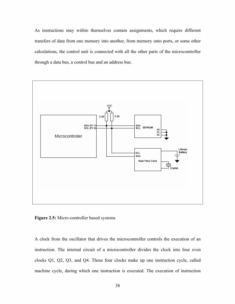
38
As instructions may within themselves contain assignments, which require different
transfers of data from one memory into another, from memory onto ports, or some other
calculations, the control unit is connected with all the other parts of the microcontroller
through a data bus, a control bus and an address bus.
Figure 2.5: Micro-controller based systems
A clock from the oscillator that drives the microcontroller controls the execution of an
instruction. The internal circuit of a microcontroller divides the clock into four even
clocks Q1, Q2, Q3, and Q4. These four clocks make up one instruction cycle, called
machine cycle, during which one instruction is executed. The execution of instruction

39
starts by calling an instruction from its memory location. The instruction is called from
the program memory on every Q1 and is written in instruction register on Q4. Decoding
and executing the instruction is done between the next Q1 and Q4 cycles
2.8.4 A computer based systems
Microprocessors have found great application in instrumentation, industrial control and
aerospace. Microprocessors are used to handle a set of tasks that control one or more
external events or systems. Microprocessors substitute programmed logic for hard-wired
logics. The programmed logic can be placed into a semiconductor read only memories
(ROMs), which have a very regular structure and hence offers even greater functionality
per chip. It has been shown that a ROM can replace a large number of standard logic
gates. Once the basic microprocessor module is built, a large number of logic power can
be added with only a few additional integrated circuits. The other or older technique of
implementing the logic product in the inter-connection of the standard hardware, is with
the logic stored in a ROM. This has permitted the designer to place nearly all of his
product logic in a very small portion of the design tool. That is, the logic is in a few
integrated circuits rather than diffused throughout the design in wiring. With the logic
concentrated in only a few components, a high degree of design flexibility is possible 4 .
Applications, problem-oriented architectures with an optimum instruction set for each use
are in great demand to improve system performance and efficiencies. The Central
Processing Unit (CPU) usually contains an execution core with two or more pipelines, a
data and address bus, a dedicated arithmetic logic unit (ALU, also called the math co-

40
processor), and in some cases special high-speed memory for caching program
instructions from RAM .
Figure 2.6 : Pentium block diagram

41
2.8 .1 Wireless technology in Greenhouse monitoring
Using wireless sensor networks within the agricultural industry is increasingly common. Gravity fed water systems can be monitored using pressure transmitters to monitor water tank levels, pumps can be controlled using wireless I/O devices, and water use can be measured and wirelessly transmitted back to a central control center for billing. Irrigation automation enables more efficient water use and reduces waste.
Wireless sensor networks are also used to control the temperature and humidity levels
inside commercial greenhouses. When the temperature and humidity drops below
specific levels, the greenhouse manager must be notified via e-mail or cell phone text
message, or host systems can trigger misting systems, open vents, turn on fans, or control
a wide variety of system responses. Because some wireless sensor networks are easy to
install, they are also easy to move as the needs of the application change.
2.9 Analogue to digital signal conversion
2.9.1 Resolution
The resolution of the converter indicates the number of discrete values it can produce
over the range of analog values. The values are usually stored electronically in binary
form, so the resolution is usually expressed in bits. In consequence, the number of
discrete values available, or "levels", is usually a power of two. For example, an ADC
with a resolution of 8 bits can encode an analog input to one in 256 different levels, since
28 = 256. The values can represent the ranges from 0 to 255 (i.e. unsigned integer) or
from -128 to 127 (i.e. signed integer), depending on the application.
Resolution can also be defined electrically, and expressed in volts. The voltage resolution
of an ADC is equal to its overall voltage measurement range divided by the number of
discrete intervals.

42
Where:
Q is resolution in volts per step (volts per output codes less one),
EFSR is the full scale voltage range = VRefHi − VRefLow,
M is the ADC's resolution in bits.
N is the number of intervals, (one less than the number of available levels, or
output codes), which is: N = 2M − 1
Some examples may help:
• Example 1
o Full scale measurement range = 0 to 10 volts
o ADC resolution is 12 bits: 212 = 4096 quantization levels (codes)
o ADC voltage resolution is: (10V - 0V) / 4095 steps = 10V / 4095 steps
0.00244 V/step 2.44 mV/step
• Example 2
o Full scale measurement range = -10 to +10 volts
o ADC resolution is 14 bits: 214 = 16384 quantization levels (codes)
o ADC voltage resolution is: (10V - (-10V)) / 16383 steps = 20V / 16383
steps 0.00122 V/step 1.22 mV/step
• Example 3
o Full scale measurement range = 0 to 7 volts
o ADC resolution is 3 bits: 23 = 8 quantization levels (codes)

43
o ADC voltage resolution is: (7 V − 0 V)/7 steps = 7 V/7 steps = 1 V/ step =
1000 mV/step
In practice, the smallest output code ("0" in an unsigned system) represents a voltage
range which is 0.5Q, that is, half the ADC voltage resolution (Q), as does the largest
output code. The other N − 2 codes are all equal in width and represent the ADC voltage
resolution (Q) calculated above. Doing this centers the code on an input voltage that
represents the M th division of the input voltage range. Doing this the "1" code spans a
voltage range from 0.5 to 1.5 V, the "2" code spans a voltage range from 1.5 to 2.5 V, etc.
Thus, if the input signal is at 3/8 ths of the full-scale voltage, then the ADC outputs the
"3" code, and will do so as long as the voltage stays within the range of 2.5/8 ths and
3.5/8 ths. This practice is called "mid-tread" operation. The exception to this convention
seems to be the Microchip PIC processor, where all M steps are equal width. This
practice is called "Mid-Rise with Offset" operation. In practice, the useful resolution of a
converter is limited by the best signal-to-noise ratio that can be achieved for a digitized
signal. An ADC can resolve a signal to only a certain number of bits of resolution, called
the effective number of bits (ENOB). One effective bit of resolution changes the signal-
to-noise ratio of the digitized signal by 6 dB, if the resolution is limited by the ADC. If a
preamplifier has been used prior to A/D conversion, the noise introduced by the amplifier
can be an important contributing factor towards the overall SNR.

44
2.9.2 Response type
2.9 2.1 Linear Analogue to digital conversions (ADCs)
Most ADCs are of a type known as linear. The term linear as used here means that the
range of the input values that map to each output value has a linear relationship with the
output value, i.e., that the output value k is used for the range of input values from
m(k + b) to m(k + 1 + b),
where m and b are constants. Here b is typically 0 or −0.5. When b = 0, the ADC is
referred to as mid-rise, and when b = −0.5 it is referred to as mid-tread.
2.9.2.2 Non-linear ADCs
If the probability density function of a signal being digitized is uniform, then the signal-
to-noise ratio relative to the quantization noise is the best possible. Because this is often
not the case, it is usual to pass the signal through its cumulative distribution function
(CDF) before the quantization. This is good because the regions that are more important
get quantized with a better resolution. In the dequantization process, the inverse CDF is
needed. This is the same principle behind the companders used in some tape-recorders
and other communication systems, and is related to entropy maximization.
For example, a voice signal has a Laplacian distribution. This means that the region
around the lowest levels, near 0, carries more information than the regions with higher
amplitudes. Because of this, logarithmic ADCs are very common in voice
communication systems to increase the dynamic range of the representable values while
retaining fine-granular fidelity in the low-amplitude region. An eight-bit A-law or the µ-

45
law logarithmic ADC covers the wide dynamic range and has a high resolution in the
critical low-amplitude region that would otherwise require a 12-bit linear ADC.

46
CHAPTER 3: MATERIALS AND METHODS
3.1 Introduction In this chapter, the experiments and the materials or apparatus used to achieve the
intended objectives are discussed. The project was divided into three parts. The first part
involves the setting up of automatic weather stations outside and inside the greenhouse.
Under the first part was the monitoring of sap flow rates under different conditions. The
second part of the project consists of the designing and the implementation of the
automatic irrigation control system. The last part of the project comprises the
investigative treatments in which the control system was compared with traditional
methods of measuring evapotranspiration rate in crops.
3.2 Experimental site
The experiments were all carried out at the University of Zimbabwe (UZ) in Harare
(17.8oS, 31.1oE and altitude 1483 m). The project was done in two places: the
Agricultural meteorology laboratory in the Physics Department and at an experimental
greenhouse in Biological Science Department. Calibrations of sensors and the
preliminary tests were carried out in the laboratory. The implementation of the control
system and the assessment of its performance were done at the greenhouse.
3.2.1 The greenhouse The experimental greenhouse Figure 3.1 was located at the Biological Science
department, UZ and was a single-span, Venlo-type greenhouse whose cladding material
was single-layered glass. The floor was concrete. The greenhouse structure and its
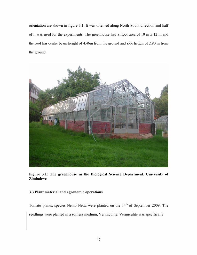
47
orientation are shown in figure 3.1. It was oriented along North-South direction and half
of it was used for the experiments. The greenhouse had a floor area of 10 m x 12 m and
the roof has centre beam height of 4.46m from the ground and side height of 2.90 m from
the ground.
Figure 3.1: The greenhouse in the Biological Science Department, University of Zimbabwe
3.3 Plant material and agronomic operations
Tomato plants, species Nemo Netta were planted on the 14th of September 2009. The
seedlings were planted in a soilless medium, Vermiculite. Vermiculite was specifically

48
used for advantages, which, among others include:
1) enhanced control of water and fertilizer applications,
2) optimal moisture in the substrate,
3) optimal nutrient supply and ,
4) Disinfecting between growing seasons.
However Vermiculite also has several disadvantages which include, among others the
following:
1) low root volume
2) low nutrient and
3) Fast changes in pH and salinity control.
The Vermiculite was put in 20litre buckets. Altogether, 128 buckets were used covering
the northern half of the greenhouse. Fertilizers were applied according to a schedule
given in Table 3.1.
Table 3.1: Program for the application of fertilizers
WEEK QUICK
START
QUICK
GROW
BEST
BLOOM
CALCIUM
NITRATE
AMMONIUM
NITRATE
NUTRIFOIL
NO1
3-6 1.125 1.25 0 0.25 0 4ml/L
7-10 0.4375 0 2.125 3.125 0.5 0
11-14 0 5 1.25 5.875 0.5 4ml/L
15-25 0 0 10 5.875 0.625 4ml/L
26-30 0 5 1.25 1.25 0.625 4ml/L

49
3.4 Instruments used
3.4 .1 Meteorological instruments
The following instruments were used in this study:
• REBS (Radiation Energy Balance Systems) net radiometer,
• A tube solarimeter,
• HMP 45C Vaisala temperature-humidity sensor,
• Wind, heated bead testo 425 anemometer,
• A matrix sensor,
• Photosynthetically active radiation ( PAR) quantum sensor,
• A CR23X Campbell Scientific (CSL) datalogger,
3.4.2 Radiation Energy Balance (REBS) net radiometer
The Q-7.1 is a high-output thermopile sensor which measures the algebraic sum of
incoming and outgoing all-wave radiation (i.e. short-wave and long-wave components).
Incoming radiation consists of direct (beam) and diffuse solar radiation plus long-wave
irradiance from the sky. Outgoing radiation consists of reflected solar radiation plus the
terrestrial long-wave component. Specifications: 60-junction thermopile with low
electrical resistance (4 ohms nominal) to reduce susceptibility to noise; Nominal
calibration factors 9.6Wm-2mV-1 (for positive values), 11.9 W m-2mV-1 (for negative
values); Spectral response 0.25 to 60µm; Uncorrected wind effect : up to 6% reduction at
7ms-1 for positive fluxes, up to 1% reduction at 7ms-1 for negative fluxes; Time constant:
Approximately 30 seconds; Top and bottom surfaces painted black and protected from

50
convective cooling by hemispherical heavy-duty polyethylene windshields ( 0.25 mm
thick) and a dessicant contained in support arm; volume of dessicant tube 45cm3;
breather port on the end of the support arm.
Figure 3.2: Radiation Energy Balance (REBS) net radiometer
3.4.3 Tube solarimeter
Tube solarimeters are designed to measure average irradiance (in W m-2) in situations
where the distribution of radiant energy is not uniform e.g. amongst foliage, in
greenhouses etc. Their tubular construction provides the necessary spatial averaging,
while minimising disturbance to the foliage of plants.
Specifications (Delta- T Devices Ltd, 1993):
• thermopile: Copper-constantan;
• Tube: Pyrex borosilicate glass; overall length 970mm, tube diameter 26mm,
• element size 858 x 22mm;
• number of junction pairs 60;
• typical internal resistance ≈25 ohms;
• approximate response time for 63% change 40s;
• approximate response time for 99% change 3min;

51
• sensitivity (Diffuse light 15mV/ kWm-2;
• Spectral range (50% points) 0.4-2.2µm;
• absolute accuracy ±10% (solar spectrum, sun angle > 30 o relative to tube axis)
Figure 3.3: A suspended tube solarimeter in the greenhouse
3.4.5 HMP45C temperature and relative humidity probe
The HPM45C temperature and relative humidity probe (Campbell Scientific Inc. (2007)
was designed to measure air temperature and relative humidity. Temperature
measurement was based on a platinum resistance thermistor (PRT). Humidity
measurement was based on Vaisala’s Humicap 180 capacitive humidity sensor, and this,
together with the precision temperature sensor, were mounted in the removable probe
head. The probe was designed to be housed in a URS1 or 41004-5 radiation shield. A 3m
cable length was fitted as standard.
Specifications (Campbell Scientific Ltd, 2007):
Relative Humidity:
measurement range 0.8 to 100% RH; Output Scale 0 to 100 % RH equals 0 to 1V DC;
accuracy (in clean air at 20oC, including non-linearity and hysterisis): Against factory
references ±1 % RH, against field references ±2% RH, to 90%, ±3% RH, 90 to 100%,

52
temperature dependence ±0.05% RH/oC ; typical long term stability ± better than 1% RH
per year; response time (at 20 oC, 90 % response) 15 s with membrane filter; humidity
sensor Vaisala Humicap 180.
Temperature- Measurement range _-39.2oC to +60 oC; operating scale_-40 oC to +60
oC equals 0 to 1V; accuracy at 20 oC_ ±0.2 oC; temperature sensor_ Pt 1000 (IEC 751 1/3
class B).
3.4.6 Wind, heated bead testo 425 anemometer
The anemometer measures wind speed in m/s, and give the air temperature in either oC or
oF. The heated bead anemometer was based on the fact that the rate at which the heated
bead dissipates heat to the environment was proportional to the wind speed causing the
heat loss. It was typically used in glasshouses where wind speeds are very low. Other
details: Testo GmGH and Co- Testo Strasse 1_D – 79853 Lenzkirch and its made in
Germany.
Figure 3.4: A Wind, heated bead testo 425 anemometer

53
3.4.7 PAR (Photosynthetically active radiation) sensor
A PAR is quantum sensor (LI-COR, Lincoln, Nebraska USA, 1986) that has been
developed to provide accurate estimates of photosynthetically active radiation by
measuring the flux of photons in the 400 to 700 nm wavelength range.
Specifications
• Sensitivity : Typically 8µA per 1000 µmol m-2s-1
• Linearity : Maximum deviation of 1% up to 10.000 µmol s-1m-2.
• Absolute calibration : ±5% traceable to the U.S National Bureau of Standards
(NBS)
• Stability: < ±2 % per annum
• Temperature dependence : -0.15 %/ oC maximum
• Azimuth error: <±1% over 360o at a 45o elevation.
• Response time : 10µs
Dimensions
• Cable length : 3.0m (10ft)
• Weight: 28g (1oz)
• Attachment : via an M3 screw in base
• Connection : Bare Wire Termination
• Sensor housing: black anodized aluminium case with acrylic diffuser and
stainless steel hardware.
54
• Weather proofing : waterproof to 1m depth of water (10m versions available on
request)
3.4.8 A matrix sensor
A matrix sensor is an instrument for measuring the solar irradiance. The sensor
construction is such that it measures the solar energy that is received from the whole
hemisphere (180o field of view). The output is expressed in Watts per metre square.
3.5 Physiological instruments
3.5.1 Copper constantan (T type) thermocouples
Thermocouples of diameter 122 µm were used for measuring leaf temperatures in the
greenhouse. These were clipped onto the underside of the leaves by plastic paper clips.
The sensitivity curves for each type of thermocouple are pre-recorded in the data logger
so that outputs were displayed in oC.
3.5.2 Sap flow gauge
The sap flow gauge used was a stem heat balance gauges (model SG10WS, Dynamax,
Inc., Houston, USA) . Sap flow gauges also known as dynagages have a soft foam collar
that surrounds the electronics. The unit is installed on a stem having an axial length of at
least the gauge height which is cleared of branches and smoothed. A weather shield is
installed for outdoor applications and radiation shielding. The O-Rings are installed and
the user must allow it enough room for its height above and the same distance below the
gauge. If only can be installed, the upper O-ring should be installed to provide insulation

55
from the rain. The specification for the gauge diameter is the determining factor for
selection of a gauge which fits properly.
Mechanical specifications
• SGA 10-ws
• Gauge height 70mm
• Shield height 180mm
• Minimum stem diameter 9.5mm
• Maximum stem diameter 13mm
• Typical stem diameter 10mm
• TC Gap dX 4.0mm
• Number of TC pairs 2
• Input voltage 4.0V
• Input power 0.10 Watts
Electrical specifications
• Minimum input voltage D.C measured at device terminals 3.5
• Typical input voltage D.C measured at device terminals 4.0
• Maximum voltage D.C measured at device terminals 5.0
• Minimum heater input power 0.06watts
• Typical heater input power 0.12 watts
• Maximum heater input power 0.15 watts

56
3.6 Electronic instruments
3.6.1 A Zener diode
A Zener diode is a semiconductor device which has a p-n junction which conducts in the
two regions. When the p region is at a higher potential than the n, holes in the p region
flow into the n region and electrons in the n region into the p region, so both contribute
substantially to current. When the polarity is reversed, the resulting electric fields tend to
push electrons in the p region, only those associated with intrinsic conductivity and some
that diffuse over from the n region. A similar conduction prevails in the n region, and the
current is much smaller than with the opposite polarity.
Specifications (RS components Midrand S.A 1999)
• Type UDZ 4-7B
• Minimum voltage 4.55V
• Maximum voltage 4.75V
• Test current 5mA
• Dynamic impedance 100Ω
3.6.2 The Velleman K8000 interface card
. Sap flow gauges are the transpiration rate indicators and they give analogue signals
which cannot be read by a computer. The Velleman K8000 interface card (shown in
Figure 3.5) was used to establish a link and convert the analogue signals to digital form
for the computer to read and after the signals had been processed by the computer the
card then changes them back to analogue for the relay switch to be actuated.

57
Figure 3.5: A Velleman K8000 interface card The Velleman K8000 is a computer interface card that allows one to control
electric/electronic devices with a computer. The card has some electrical inputs and
outputs. The K8000 runs on IBM compatible computers, and can be connected to a
computer through a standard parallel cable. The card can be programmed in any
programming language, such as Visual Basic, C/C++, Q Basic, Turbo, Pascal e.t.c. In
addition, a software called Power WinPLC can be used to program the card. Power
WinPLC provides a good environment to create applications for the K8000 card. The
K8000 card provides 16 I/O channels, which can be configured as in- or output. Digital
inputs can read the state of switches. The outputs can set relays etc. the K8000 had also 9
analogue inputs and 4 analogue outputs.
Inputs from sensor
IO channel outputs
Opto-couplers
LEDs
Cables from mains
Secondary transformer
Serial printer cable

58
Features
• Optically isolated from computer
• 16 optically isolated digital connections
• 9 analogue outputs, of which one was high precision and 4 analogue inputs.
• A simple way of controlling using Visual Basic, C/C++, Q Basic, Turbo Pascal
• Printer bypass connector on board,
• Simple connection with printer port
Specifications
Digital outputs:
Optocoupler, open collector output; 50mA- max.30VDC
Analogue inputs:
Optocoupler input: 5V/%mA, max.20V/40mA,
Analogue outputs
• 8 outputs DAC1 to DAC 8, resolution: 64 steps
• Minimum output voltage 0.1V at 2mA
• Maximum output voltage 11.5V adjustable at 2mA
• Resolution per step from 0.1 to 11.5V: 160mV +/- 90mV,
• 1 precision output voltage DA1, resolution: 256 steps.
• Minimum output voltage :0V
• Maximum output voltage : 4.5V adjustable at 0.5mA
• Resolution per step from 0 to 4.5V: 17.5mV

59
Analogue Inputs
• 4 analogue inputs AD1 to AD4, resolution: 256 steps
• Minimum input voltage :0V
• Maximum input voltage 5V
• Input impedance : 50ohms
• Resolution: 19.5mV
Other features
• Communication protocol : I2C bus
• LED indication for each I/O.
• 25 pin D series connector for computer
• 25 Pin D series connector for printer
• Supply voltage :230Vac
PCB dimensionas: 237 x 133mm(9.3”x5.2”)
(http:/bvsystems.be/k8000)

60
3.6.3 A universal K6714 relay card
Figure 3.6: A universal K6714 relay card
The K6714 Universal Relay Card (8 Relays) self-assembly electronic construction kit
was ideal for switching large electric currents using an electronic control while
controlling isolation at the same time.The circuit board is powered by 125-230Vac mains.
Power supply transformer was included and provides a 12V DC output that can be used
as a power supply for other kits e.g., K8023. Every output of the print can be equipped
Power indicator LED
Input ports
TransformerA relay switch
Power input port

61
with a noise suppressor network. It provides 16 channels but components to populate
only the first 8 channels are provided.
Features
• 8 relays included (extendible to 16)
• the relays can be controlled in different ways:
o direct control from open-collector outputs, TTL or CMOS level
o other kits like K8000, K8023, K6711, ...
• Contact: 1 x inverter: 10A / 28VDC or 125VAC, max. 5A at 230VAC
• Relay switch-over contact: max. 5A at 220V
Specifications
• output voltage: 12V / 250mA for power supply
• power supply: 220 or 115VAC / 12VA
• PCB dimensions: 150 x 212mm (5.9" x 8.4")
• recommended housing: WCAH2507
• Product format: self assembly electronic construction kit
3.6.4 Electric pump
The pump used was the Pedrollo San Bonifacio (VR) type of pump and made in Italy. It
ejects water at a rate of 0.125 litres per minute.

62
3.7 Computer software used
3.7.1 Power WinPLC
Power WinPLC was a software tool to control the Velleman Interface card K8000. The
program helps to construct applications very quickly, with as little commands as possible.
Setting an I/O channel only takes a single line with WinPLC, doing the same in Visual
Basic requires dozens of lines. WinPLC had 10 groups with several commands one can
use in applications. They vary from special commands like IF …THEN to networking
commands, allowing one to connect to other computers very quickly. The language for
the programming was a sort of scripting language. It includes subroutines, labels, IF-
statements, I/O basic operations, DAC basic operations, time functions. To run K8000
applications, WinPLC always must be started.
3.7.2 Visual Basic, VB. Net Studio 2005
A programming language called VB. Net Studio 2005 was used to code the control
program. The program and commands are given in annex A. Installation of the VB.Net
software was done and the computer had Windows XP as the operating system. Some
commands of the WinPLC language were used within the program to call, set and clear
the channels on the K8000 card.
3.8 Calibration of sensors All meteorological and physiological sensors lose accuracy with time after they have
been manufactured. It was essential that before these sensors are taken for field use they
are calibrated against standard ones and the accuracy limits should be within those
stipulated by the manufacturer. Several experiments were carried out in the Agro-

63
meteorology laboratory and on the roof top of Physics department, University of
Zimbabwe to obtain readings from the temperature- humidity sensors and radiation
sensors.
3.8.1 Experiment 1: Calibration of temperature humidity sensors (Vaisala type)
The temperature humidity sensors calibrated were the Vaisala HMP45AC type and the
Delta-T type and the Walz system ( Dewpoint system TS-2, Mess-unit and
GegelTechnik) was used as a standard. The experiments were done separately since the
two types of sensors use different dataloggers and due to limited resources. Two Vaisala
HMP45AC type sensor (serial numbers A0640010, A0130013) were tied together with a
platinum resistance thermometer and a Walz system tube and inserted into a hollow
cylinder in which the air temperature was presumed to be similar to the water bath
temperatures if there were no energy losses. A program was designed using PC208W
Campbell computer package with consultations from the sensors’ manuals available and
fed into the Campbell datalogger CR10X and CR23X (serial number 14397 and 4081
respectively) from a laptop. The program made it possible for the logger to record
temperature and humidity readings from the Vaisala and the Walz sensors every minute
and also gave averages and standard deviations. A fixed temperature was set on the water
bath and about five temperatures were set on the Walz dewpoint generator but the latter
temperatures had to be below the former always to avoid condensation inside the pipes of
the Walz system that occurs when temperatures equalled. For each dewpoint temperature
set the system was left to stabilize for at least 10 minutes to allow for accuracy in the

64
measurements. This procedure was done for water bath temperatures from 1oC to 40oC.
The data was downloaded later to a laptop for analysis. The multipliers obtained from the
straight line figures gave evidence to the accuracy of the sensors. The accuracy proposed
by the manufacturer must be within ± 0.2 % of the original multiplier otherwise the new
multiplier had to be adopted.
3.8.2 Experiment 2: Calibration of radiation sensors
Radiation sensors which comprise the CM11 solarimeter ( Kipp and Zonen Delft,
Netherlands) and one tube solarimeters (serial numbers 24) were set up on the Physics
department open air rooftop and connected to a Campbell CR23X datalogger (serial
number 4081). The CM11 solarimeter was used as the standard against which all the
other radiation sensors were compared. The sensors were all leveled and checked for
dryness before they were left to run. The tube solarimeters was oriented along the north-
south direction to increase surface area of incident radiation according to Monteith
(1993). A program was written with consultations from the manuals of corresponding
sensors using a keypad on the logger. The sensors were left to give readings for four
days and four nights (20 August to 24 August 2009) after which the data was downloaded
and read in excel spreadsheets. The multipliers obtained from the regression line gave
evidence to the accuracy of the sensor.
3.9 Preliminary measurements and tests
3.9.1 The integrity test
The integrity test was done to calibrate the analogue input AD channels using the
nominal values from a power supply with regulated d.c.voltage outputs. A program was

65
coded using Visual Studio 2005 language to read the voltages of the channels. Each
channel was subjected to nominal voltages and checked if it was reading true values. The
results for the four channels are shown in Table 4.4.
Figure 3.7 A setup for the integrity test
3.9.2 Analogue voltage signal conversion to digital signal resolution test
An experiment was carried out in the Agro-meteorology laboratory in which the set up
was similar to the one for the integrity test. A simple program was coded in VB.Net
language which read voltage inputs on the analogue input port of the K8000 card. A
voltage regulated power supply was used as the source for analogue signals and the
program when run displayed the corresponding digital values for the input signals.
Sixteen values for the analogue signals were sent in and the corresponding digital signals
are as tabulated in Table 4.3. A regression curve for the two signals was subsequently
plotted to show the degree of agreement between the two.
A d.c power supply
A K8000 card
A K6714 relay card
Voltage inputs
A computer

66
3.9.3 Amplification of sap flow gauge signals
The three output signals from the sap flow gauges i.e. AH, BH and CH are too low (i.e.
range from 0 to 0.4mV) to be accepted and processed by the K8000 card, amplification
was necessary. To amplify, three CA3201E operational amplifiers were employed and
assembled as shown in figure 3.5. The gain of the amplifier was set using the external
resistors combination i.e. a preset feedback resistor of 25 kΩ and an input resistor of 22 Ω
to determine the gain for each amplifier. A preliminary experiment was carried out in
which the amplified voltage signals were recorded against the actual voltages from the
sensor. This experiment was done in order to provide the computer program with known
voltages that can be read in the program as millivots. Small changes in millivolt ranges
were registered as well in the amplified voltages.
+ Figure 3.8 A schematic diagram of the negative gain amplifying circuit
3.9.4 Designing of a computer program
The computer program was coded using VB.Net 2005 (Visual Basic language). The
program accepted inputs that were coming from a sap flow gauge sensor as voltages. It
25 kΩ
22 Ω
CA3201E
A zener diode

67
calculated the amount of water lost from the crop and then sent a command to the relay
switch to turn on the irrigation pump to replace the lost water.
3.9.4.1 A flow chart for the control program (algorithm)
The program was written using Visual Basic .NET 2005 version language. The flow chart
in figure 3.9 shows the sequence of events in the program

68
Figure 3.9: A flow chart for the computer control program The computer program was made of five parts. The first was entitled the ‘Public Class
Form 1’. Under this class are declarations of global variables (variables that can be used
in any sub class). The second part of the program comprise of a function given a name
‘ppp’. Under the function are some declarations of certain variables made followed by
WinPLC statements (i.e. winplc.getADState) that are meant to read the analogue input
channels of the K8000 card. The next part of the function was made of mathematical
Public class: declares variables
Form 1-load: timers 1&2 are started, refreshing inputs as they change
Private function ppp( ):reads inputs, calculates transpiration rate
Timer1_Tick: gives time when transpiration rate should be calculated i.e. after every 15minutes
Timer2_Tick: gives time to set IO channels or to energise the relays. Transpiration rate (TR) was summed up to the previous reading except negative TR readings
Timer3_Tick: takes the time to irrigate calculated from the water lost and the drip emitter rate

69
equations to compute the water lost estimated by a sap flow gauge sensor. The last part of
the function was made of commands for textboxes which display the input signals from
the sensor when the program was running. The function was followed by timers. Under
the first timer dubbed ‘Timer1’ was a command that starts the ticking of the timer as soon
as the application (program) starts running. When Timer1 ticks the function ‘ppp’ was
called and everything under the function was executed. Timer 1 determines the time
when transpiration rate of the crop was measured and that was after 15 minutes.
Transpiration (TR) was added only when it was greater than zero. Timer 2 sub class
follows. Timer 2 ticks as soon as the application starts running and was executed after 24
hours. Timer 2 determines the time to switch on the irrigation pump to replace the lost
water. The third timer which was Timer 3 takes the time calculated from the water lost
and the drip emitter rate. Under timer 3 was a command to energize the relay switch i.e.
set IOch and a command that switches the relays off i.e. clear IO ch when irrigating
interval had elapsed. The program was given in Annex C.
3.10 Field measurements
3.10.1 Setting up of an automatic weather station inside the greenhouse
An automatic weather station shown in figure 3.1 was set up at the greenhouse in the
Biological Science department, University of Zimbabwe. The station measures both
meteorological and physiological variables and the sensors were all sending readings to a
CR23X Campbell Scientific (CSL) datalogger. Weather parameters measured include

70
solar radiation (measured by CM3 pyranometer), photosynthetically active radiation
(using a PAR sensor), air temperature and relative humidity (measured by a Vaisala
temperature-humidity sensor) and net radiation (measured by a REBS (Radiation Energy
Balance Systems) net radiometer. Other variables measured were the sap flow rate of
tomato crops (measured by a stem heat energy balance gauge), soil temperature (using
soil temperature probe) and leaf temperatures (using chrome-constantan type
thermocouples).
3.10.2 Setting up of an automatic weather station outside the greenhouse
The station measured fewer variables and these are only meteorological. It comprise
sensors like CM3 pyranometer, a Vaisala temperature-humidity sensor estimating same
variables mentioned for the inside station on common sensors. All the sensors were
sending readings to a CR23X CSL datalogger.

71
Figure 3.10 (a) an automatic outside weather station and (b) shows the bottom part
of the automatic weather station inside a greenhouse at the Biological Science
Department, UZ
3.10. 3 Data collected from the sensors
Programs 1 and 2 given in annexes B and C were loaded onto the outside and the
inside greenhouse loggers respectively. The inside automatic weather station
datalogger (CR 23 X) sampled data every 5 seconds and averaged it every 15
minutes. Data was downloaded as .DAT files and processed in the Excel spreadsheet.
A temperature-humidity sensor (Vaisala type)
A Campbell scientific datalogger (CSL)
A tomato crop in greenhouse
(b)
(a)

72
The data for the outside the green house weather station was sampled by a CR 10X
datalogger every 5 seconds and averaged over 30 minutes. It was as well processed in
Excel spreadsheets. Solar radiation was in units of W/m2, net radiation was read in
units of W/m2, air temperature in oC, relative humidity as % and PAR in µmol m-2 s-1
3.10.3.1 Installation of sap flow gauge sensors
The sap flow gauge was mounted as shown in figure 3.8. A straight stem was selected
carefully from a tomato crop. The branch’s diameter was measured with vernier calipers
and found to have an average of 9.1mm which corresponded to the inscribed gauge
diameter of 10mm. A cloth was used to clean the branch and some canola oil was sprayed
onto the branch to prevent the shoots or buds from emerging during the experiment as
this will damage the gauge or result in the gauge giving erroneous readings. Before
installing the gauge, the voltage which was meant for heating of the gauge had to be
regulated by a voltage regulator to the required level, which in this case was 4V dc. The
data logger was programmed to allow for the recording of sap flow measurements every
15 minutes. An automatic weather station measured weather parameters such as air
temperature, humidity and radiation: variables which had influence on the rate of sap
flow and ultimately on the transpiration rate.

73
Figure 3.11: Showing a stem heat balance sap flow gauge installed onto a tomato crop
3.10.3.2 Determination of Ksh
The stem heat balance sap flow gauges to be used with the card had a sheath coefficient
(Ksh) which was a property of how the sheath conducts heat and these coefficients were
calculated after an experiment was done. Two sap flow gauges were mounted around
tomato crops in the greenhouse at the Biological Science department, University of
Zimbabwe. The gauges were connected to a Campbell CR23X, Z10 datalogger and were
left to give readings for two days and two nights. It was experimentally proved that
transpiration rate for many greenhouse crops was zero or very close to zero just before
dawn (between 4am and 6 am) the component Qf will be zero and Ksh will be calculated
from equation (2.17)
3.10.3.3 Determination of stem diameters and cross sectional areas
A micrometer screw gauge with an accuracy of 0.01 mm was used to measure the stem
diameters of two tomato crops on which the sap flow gauges were mounted. For each
plant three measurements were done to minimize the random error on the results. The

74
results were used in the calculation of the stem cross sectional area for the calculation of
the flow rates for the sap flow gauges. Results for these measurements are tabulated in
Table 4.5
3.11 Monitoring of transpiration rates from sap flow rates
Transpiration rates differ with changes in the microclimate of a greenhouse. Sap flow
rates under different conditions were monitored by having two sap flow gauges to record
the transpiration rates for the tomato crops in the greenhouse for ten days (day 32 to 41 in
2010). The data was downloaded and analysed in Excel spreadsheets. The data was
important in one way that it set some limits or gave an idea of the amount of water lost
under certain conditions. This information helped in the designing of the computer
program and ultimately had a bearing on the irrigation schedule. A comparison of the
transpiration rates registered by the sap flow gauges and those computed from weather
data according to the FAO Penman-Monteith equation was done. The analyses for these
comparisons are given in form of a graph in Figure 4.36.
3.11.1 The scaling up of the estimated evapotranspiration
Transpiration rate estimated by sap flow gauges was upscaled to be representative of the
whole cropped area where it was measured using the method suggested by Katsoulas et al
in 2001. In this method the leaf area index LA in m2 (leaf) m-2 (ground) was estimated
from leaf length measurements L in m, using the relationship : S = 0.26L2, linking the
area S in m2 of a leaf to L .

75
3.12 Monitoring of transpiration rates using the FAO Penman –Monteith equation
The FAO Penman-Monteith method employs meteorological variables to estimate crop
evapotranspiration. Ten consecutive days (day 32 to day 41, 2010) data from the
automatic weather station inside the greenhouse was read and analysed in the Excel
spreadsheet to compute ETo. The variables that were of interest in this method were the
relative humidity, the air temperature, solar radiation, and net radiation. The wind speed
was estimated manually using a hot wire anemometer and an average for every hour was
recorded. Equation 2.6 was used to compute hourly ETo and it was given in mm per hour
as units. A table of results and Figures were plotted to show how the calculated ETo
varied with the weather parameters.
3.12.1 Determination of the wind speed using the hot wire anemometer
A hot wire anemometer was used to estimate the windspeed inside the greenhouse.
Sampling method was used in which readings were taken randomly at different places
inside the greenhouse. About 25 readings were taken and averaged out to give the mean
windspeed inside the green house. The results of the exercise were seen to be very
irregular and an average value of 0.4 ms-1 was used in the estimation of ETo using the
FAO Penman-Monteith equation.
3.13 Monitoring of the system signals with the data logger signals
The three signals (AH, BH and CH) sent to the K8000 card had to be the same as the
signals read by the datalogger. A setup as shown in figure 3.12 was put in place and the
computer program was designed to register 15 minute interval data. The set up was made
to run for ten hours during daytime from which the data was collected and analysed. Data

76
from the data logger was downloaded and read in an Excel spreadsheet in which a
regression analysis between logger data (standard) and the system was done.
Figure 3.12: A setup monitoring signals from data logger to the amplifying circuit
3.14 Measurement of the drip emitter rate
An experiment was carried out in the greenhouse to measure the drip emitter rate when
the pump was supplying water. Four drip pipes were inserted into a 2 litre container and
were timed for the filling of the container with water when the pump was switched on.
The experiment was done three times on different pipes to minimize error and the results
were tabulated in Table 4.7 the emitter rate was used to calculate the time allocated for
the pumping of water from the reservoir tank.
A CSL datalogger
A multimeter
A bread board
CA3201E op-amps
A potentiometer
Wires from datalogger to amplifiers
A voltage regulator

77
3.15 Integration and implementation of control system
The electrical pump was connected onto the relay card and was controlled by the
computer program which after calculating the transpiration rate gives the time the pump
had to run. The outline of a sequence of steps was given in the flow chart given in figure
3.13.

78
3.15.1 The flow chart of the control system (algorithm)
This flow chart will show a sequence of events in the irrigation control system
Figure 3.13: A flow chart for the irrigation control system
Datalogger with sap flow signals
AH,BH,CH signals amplification
Computer with a control program
K6714 universal relay card
Irrigation valve and pump
K8000 interface card
Vin signal
Plants & sap flow sensors

79
3.15.2 The irrigation control system
Figure 3.14 is showing the proposed irrigation control system when it was implemented in the greenhouse with a tomato crop.
Figure 3.14: (a) An irrigation control system (b) connections from the datalogger to
the cards (c) A pump connected to the water tank (reservoir) and supplying water to
the crops, (d) A pipe from the pump leading to the potted plants.
(a) (b) (d)
Pump power cable connected to the relay
Pump Relay card
(c)
Computer monitor

80
3.15.2.1: Connection between the K8000 card, relay card and the pump
Figure 3.15: Connection between the K8000 card, relay card and the pump
One pump was used in the project so one relay switch was used. The setup in figure 3.15
is used when more than one pump is used.
3.15.3 A computer display of the running system
Figure 3.16 shows a page of the application interface for the program. In the page were
textboxes indicating the four input voltage signals i.e. Vin, AH, BH and CH, give the
transpiration rate computed every 15 minutes and 24 hours, and finally had list boxes that
Pumps

81
show the daily water loss, the time given to the pump and the day on which the irrigation
took place.
Figure 3.16: A computer display of the running system
3.15.4 Investigative crop treatments Three treatments were set up as shown in figure 3.17. The first treatment was made of a
tomato crop bed whose evapotranspiration rate was to be estimated from the FAO
Penman–Monteith equation (equation 2.6) which was the current grower practice. The
second treatment was an automated one with sap flow gauges measuring the
evapotranspiration and sending the signals to a computer to determine how much water to

82
be replaced. The last treatment was a stressed one which was used in principle as the
control and evapotranspiration was estimated using the FAO Penman –Monteith equation
again.
Figure 3.17: A setup of investigative crop treatments Key M1 A potted tomato plant M2 A drip line M3 A T type thermocouple M4 A water supply pipe M5 A sap flow gauge M6 A T type thermocouple M7 An automatic weather station inside the greenhouse
A B C
M1
M2
M3
M4 M6 M5
M7

83
Copper constantan (T-type) thermocouples were attached to leaves of the three treatments
since loss of water has a strong bearing on the leaf temperatures. Variation of the leaf
temperatures was monitored for the stressed treatment and the current grower’s practice
treatment. Reference crop evapotranspiration in all the treatments was finally read in
mm/day units and compared to see how they varied. Cooling of the greenhouse was
achieved by employing a fan that was electrically driven.

84
CHAPTER 4
RESULTS AND DISCUSSION
4.1 Introduction
This chapter is composed of calibration of instruments used; data analysis for the
monitoring of sap flow rates under different weather conditions; the testing of the system
results and the comparison of the control system in terms of total water used with the two
other treatments. The chapter in addition had an in depth discussion on all the results
obtained.
4.2 Calibrations
Table 4.1: Calibration of relative humidity temperature sensor
Sensor Serial number Calibration equation HMP 45C (RH output) A0130013
RH(walz)= 0.733*RH 600
HMP 45C( Temp output) A0130013
TM(walz) = 0.92*TM 600
HMP 45C (RH output) A0640010 RH(walz)= 1.017*RH 602 HMP 45C( Temp output) A0640010 TM(walz) = 0.96*TM 602 The HMP 45C calibration have a high accuracy value for the temperature component as
the multiplier values are 92% and 96% and have a less accuracy for the relative humidity
component with 73.33 % and 101.7 % for the calibration multipliers.

85
Table 4.2: Calibration of radiation sensors with the CM11 Kipp solarimeter (serial number 997082 and multiplier 5.22µV/Wm-2 ±0.5%) as the standard
Sensor Serial number Calibration equation Tube solarimeter 24 TSL 24= 0.72313*CM11-
0.3176
The calibration multiplier for the tube solarimeter was 72.313 %. This was adopted as its
new multiplier for the readings obtained from it.
Table 4.3: Voltage results used to convert analogue signals to digital signals (resolution test)
Analogue voltage signal (V) Digital voltage signal (V)
0.05 10 0.95 51 1.03 58 1.51 88 2.00 105 1.99 108 2.35 128 2.83 149 3.00 158 3.28 172 3.90 208 4.00 211 4.14 220 5.00 255
Table 4.3 shows the results of a resolution test that was carried out to see the conversion
of analogue signal to digital signal. It was clearly observed that there was strong
agreement between the two variables. The analogue voltage signal of 5 volts
corresponded to the maximum digital equivalence of 255 volts.

86
Table 4.4: Results of an integrity test of the K8000 Velleman interface card AD1 Channel AD2 Channel AD3 Channel AD4 Channel Nominal (V)
Observed (V)
Nominal (V)
Observed(V)
Nominal (V)
Observed (V)
Nominal (V)
Observed (V)
0.50 0.491 0.99 0.945 0.80 0.782 1.00 0.964 1.01 0.964 1.50 1.436 0.99 0.945 1.51 1.455 1.52 1.455 2.05 1.964 1.10 1.054 1.80 1.727 2.02 1.927 2.56 2.455 1.66 1.600 1.90 1.818 2.65 2.545 3.06 2.927 1.75 1.673 2.08 2.000 3.00 2.873 3.50 3.345 2.00 1.909 2.61 2.491 3.51 3.364 3.91 3.745 2.50 2.400 3.06 2.927 4.02 3.836 4.04 3.873 3.11 2.964 4.03 3.855 4.50 4.291 4.47 4.273 4.00 3.818 Table 4.4 show results obtained from calibration of the AD channels. Input voltages of
values from 0.49 to 4.5 volts were used. Using the conversion of analogue signal to
digital from resolution test a factor of 1/55 was used to get the equivalent analogue
readings from the card. These results show that there is high correspondence between the
compared variables and the card can be used to give precise readings.
4.3 The computation of sap flow rates
Table 4.5: Leaf dimensions used to calculate total leaf area from a theory postulated by Katsoulas et al (2001) Leaf number Leaf length (m) Total leaf area(m2)_0.26L2 1 0.085 0.00187850 2 0.083 0.00179114 3 0.065 0.00109850 4 0.070 0.00127400 5 0.057 0.00084474 6 0.067 0.00116714 Average total leaf area
0.26846733

87
Table 4.6: Readings used for calculating the stem cross sectional area Stem diameter_ plant 1 Stem diameter_ plant 2 10.05mm 9.03mm 10.31mm 9.41mm 10.42mm 9.36mm 10.26mm 9.27mm Average diameter 0.01026 m 0.009268 m Cross sectional area 8.27E-05 m2 6.75E-05 m2
4.3 Monitoring of sap flow rates Monitoring of sap flow rates under different weather conditions was done using results
that were taken from a ten day (day 32 to day 41, 2010) recording with a Z10 CR 23X
CSL data logger. The results are based on one sap flow gauge. Four days were chosen to
give graphical picture of how the sap flow rate varied with other weather parameters i.e.
days 32, 33, 38 and 39.
4.3.1 Temporal variation of weather parameters on different days inside the greenhouse
Temporal variation of weather parameters entails time variation of weather variables
inside the greenhouse. Weather variables influence its microclimate and most importantly
the crop evapotranspiration rate of crops.

88
0
0.1
0.2
0.3
0.4
0.5
0.6
0.7
0 50 100150200250300350400450500550600650700750800850900950100010501100115012001250130013501400145015001550160016501700175018001850190019502000205021002150220022502300
Time (hrs)
Rad
iatio
n (M
Jm^-
2min
^-1)
0
5
10
15
20
25
30
35
40
Air
tem
pera
ture
(deg
C)
Net radiation Solar radiation Air temperature
Figure 4.1: Temporal variation of radiation and air temperature on day 32, 2010
0
0.1
0.2
0.3
0.4
0.5
0.6
0 50 100150200250300350400450500550600650700750800850900950100010501100115012001250130013501400145015001550160016501700175018001850190019502000205021002150220022502300
Time (Hrs)
Rad
iatio
n (M
Jm^-
2min
^-1)
0
5
10
15
20
25
30
35
Air
Tem
epra
ture
(deg
C)
Net radiation Solar radiation Air temperature
Figure 4.2: Temporal variation of radiation and air temperature on day 33, 2010

89
0
0.1
0.2
0.3
0.4
0.5
0.6
0.7
0 50 100150200250300350400450500550600650700750800850900950100010501100115012001250130013501400145015001550160016501700175018001850190019502000205021002150220022502300
Time (hrs)
Rad
iatio
n (M
Jm^-
2min
^-1)
0
5
10
15
20
25
30
35
40
45
Air
tem
pera
ture
(deg
C)
Net radiation Solar radiation Air temperature
Figure 4.3: Temporal variation of radiation and air temperature on day 38, 2010
0
0.1
0.2
0.3
0.4
0.5
0.6
0.7
-5 45 95 145195245295345395445495545595645695745795845895945995104510951145119512451295134513951445149515451595164516951745179518451895194519952045209521452195224522952345
Time (hrs)
Rad
iatio
n (M
Jm^-
2min
^-1)
0
5
10
15
20
25
30
35
40
45
Air
tem
pera
ture
(deg
C)
Net radiation Solar radiation Air temperature
Figure 4.4: Temporal variation of radiation and air temperature on day 39, 2010

90
Figures 4.1 to Figure 4.4 are showing diurnal variations of solar radiations, net radiations
and air temperature. The general forms of the curves are similar for the three variables
with minimum values attained at night and maximum values between noon and 2 pm. Air
temperatures attain their peak values an hour or two after the radiations and this was
normal since temperature was a response to incoming radiation i.e. high radiation result
in high temperature and less radiation in low temperatures. In addition air had a low heat
capacity hence the time delay in attaining the peak value. Partially cloudy skies caused
fluctuations in net radiation and solar radiation wave forms.
4.3.2 Temporal variation of sap flow rate on different days
0
5
10
15
20
25
0 50 100150200250300350400450500550600650700750800850900950100010501100115012001250130013501400145015001550160016501700175018001850190019502000205021002150220022502300
Time (hrs)
Sap
flow
rate
(g/h
r)
Figure 4.5: Temporal variation of sap flow rate on day 32

91
0
5
10
15
20
25
30
35
0 50 100150200250300350400450500550600650700750800850900950100010501100115012001250130013501400145015001550160016501700175018001850190019502000205021002150220022502300
Time (hrs)
Sap
flow
rate
(g/h
r)
Figure 4.6: Temporal variation of sap flow rate on day 33
0
10
20
30
40
50
60
70
0 50 100150200250300350400450500550600650700750800850900950100010501100115012001250130013501400145015001550160016501700175018001850190019502000205021002150220022502300
Time (hrs)
Sap
flow
rate
(g/h
r)
Figure 4.7: Temporal variation of sap flow rate on day 38

92
0
10
20
30
40
50
60
70
0 50 100150200250300350400450500550600650700750800850900950100010501100115012001250130013501400145015001550160016501700175018001850190019502000205021002150220022502300
Time (hrs)
Sap
flow
rate
(g/h
r)
Figure 4.8: Temporal variation of sap flow rate on day 39 Figures 4.5 to Figures 4.8 show diurnal variations of sap flow rates on four different days.
All the figures show the same form as they attain their minimum values at night, early
morning hours and late afternoon hours. Some uncharacteristic drops of sap flow rates
readings to zero around noon time could be attributed to technical problems in the gauges
which sometimes arise due to poor shielding or brief power cuts or due to midday
stomatal closure. Early morning and nighttime readings were recorded as negative values
but in principle should be read as zero flow rates. The variation of sap flow rate was in
line with the theory in which transpiration rate was induced by the incoming solar
radiation and thermal radiation trapped by the green house.

93
4.3.4 Variation of sap flow rate with solar radiation
0
0.05
0.1
0.15
0.2
0.25
0.3
0.35
-5 45 95 145195245295345395445495545595645695745795845895945995104510951145119512451295134513951445149515451595164516951745179518451895194519952045209521452195224522952345
Time (hrs)
Sola
r rad
iatio
n (M
Jm^-
2min
^-1)
0
5
10
15
20
25
Sap
flow
rate
(g/h
r)
Solar radiation Sap flow rate (g/hr)
Figure 4.9: Temporal variation of sap flow rate and solar radiation on day 32, 2010
0
0.1
0.2
0.3
0.4
0.5
0.6
0 50 100150200250300350400450500550600650700750800850900950100010501100115012001250130013501400145015001550160016501700175018001850190019502000205021002150220022502300
Time (hrs)
Sola
r rad
iatio
n (M
Jm^-
2min
^-1)
0
5
10
15
20
25
30
35
Sap
flow
rate
(g/h
r)
Solar radiation Sap flow rate
Figure 4.10: Temporal variation of sap flow rate and solar radiation on day 33, 2010

94
0
0.1
0.2
0.3
0.4
0.5
0.6
0 50 100150200250300350400450500550600650700750800850900950100010501100115012001250130013501400145015001550160016501700175018001850190019502000205021002150220022502300
Time (hrs)
Sola
r rad
iatio
n (M
Jm^-
2min
^-1)
0
10
20
30
40
50
60
70
Sap
flow
rate
(g/h
r)
Solar radiation Sap flow rate
Figure 4.11: Temporal variation of sap flow rate and solar radiation on day 38, 2010
0
0.1
0.2
0.3
0.4
0.5
0.6
0 50 100150200250300350400450500550600650700750800850900950100010501100115012001250130013501400145015001550160016501700175018001850190019502000205021002150220022502300
Time (hrs)
Sola
r rad
iatio
n (M
Jm^-
2min
^-1)
0
10
20
30
40
50
60
70
Sap
flow
rate
(g/h
r)
Solar radiation Sap flow rate
Figure 4.12: Temporal variation of sap flow rate and solar radiation on day 39, 2010

95
Figure 4.9 to figure 4.12 are showing diurnal variation of sap flow rate with solar
radiation. It is quite apparent the sap flow rate graphs followed the shape of the solar
radiation which shows that solar radiation is the driving factor of water loss in these
crops. There is a time lag though between the time when the sun rises and the beginning
of sap movement as with day 39 and 38 showing a short time lag of a few minutes just
after sunrise and on day 32 and 33 there is a significant time lag of a few hours.
4.3.5 Variation of sap flow rate with relative humidity
0
10
20
30
40
50
60
70
80
90
100
0 50 100150200250300350400450500550600650700750800850900950100010501100115012001250130013501400145015001550160016501700175018001850190019502000205021002150220022502300
time (hrs)
Rel
ativ
e hu
mid
ity %
0
5
10
15
20
25
Sap
flow
rate
(g/h
r)
relative humidity % Sap flow rate (g/day)
Figure 4.13 Temporal variation of sap flow rate and relative humidity on day 32, 2010

96
0
10
20
30
40
50
60
70
80
90
100
0 50 100150200250300350400450500550600650700750800850900950100010501100115012001250130013501400145015001550160016501700175018001850190019502000205021002150220022502300
time (hrs)
rela
tive
hum
idity
%
0
5
10
15
20
25
30
35
Sap
flow
rate
(g/h
r)
Relative humidity % Sap flow rate (g/day)
Figure 4.14: Temporal variation of sap flow rate and relative humidity on day 33, 2010
0
10
20
30
40
50
60
70
80
90
0 50 100150200250300350400450500550600650700750800850900950100010501100115012001250130013501400145015001550160016501700175018001850190019502000205021002150220022502300
time(hrs)
Rel
ativ
e hu
mid
ity %
0
10
20
30
40
50
60
70
sap
flow
rate
(g/h
r)
Relative humidity % Sap flow rate (g/day)
Figure 4.15: Temporal variation of sap flow rate and relative humidity on day 38, 2010

97
0
10
20
30
40
50
60
70
80
90
100
0 50 100150200250300350400450500550600650700750800850900950100010501100115012001250130013501400145015001550160016501700175018001850190019502000205021002150220022502300
time(hrs)
Rel
ativ
e hu
mid
ity %
0
10
20
30
40
50
60
70
Sap
flow
rate
(g/h
r)
Relative humidity % Sap flow rate (g/day)
Figure 4.16: Temporal variation of sap flow rate and relative humidity on day 39, 2010 Figure 4.13 to Figure 4.16 show diurnal variations of sap flow rates and relative humidity
on four different days. The wave forms of relative humidity have contrasting shapes with
the sap flow rate attaining their minimum during the night, early morning hours and late
afternoon hours. Relative humidity on the other hand attained its maximum at night and
minimum during the day.
4.3.6 Correlation between sap flow rate and weather parameters
Regression analysis was done between sap flow rate results against solar radiation and to
give a statistical interpretation of the level of agreement.

98
Table 4.7: A summary of sap flow rate values and relative humidity values for four days
Relative humidity % Sap Flow g/hr
Day of year in 2010
Maximum Minimum
sum
32 90.7 10.10188 10.10188 33 89.6 18.63174 18.63174 38 84.3 38.96096 38.96096 39 86 43.27104 43.27104 4.3.5 Variation of sap flow rate with daytime solar radiation
y = 20.498x + 0.0159R2 = 0.1549
0
5
10
15
20
25
0 0.05 0.1 0.15 0.2 0.25 0.3 0.35
Solar radiation (MJm-2min^-1)
Sap
flow
rate
(g/h
r)
Figure 4.17: Correlation between sap flow rate and solar radiation on day 32

99
y = 25.456x + 4.5038R2 = 0.1018
0
5
10
15
20
25
30
35
0 0.1 0.2 0.3 0.4 0.5 0.6
Solar radiation (MJm^-2min^-1)
Sap
flow
rate
(g/h
r)
Figure 4.18: Correlation between sap flow rate and solar radiation on day 33
y = 41.145x + 9.6975R2 = 0.171
0
10
20
30
40
50
60
70
0 0.1 0.2 0.3 0.4 0.5 0.6
Solar radiation (MJm^-2min^-1)
Sap
flow
rate
(g/h
r)
Figure 4.19: Correlation between sap flow rate and solar radiation on day 38

100
y = 46.068x + 8.0539R2 = 0.1982
0
10
20
30
40
50
60
70
0 0.1 0.2 0.3 0.4 0.5 0.6
Solar radiation (MJm^-2min^-1)
Sap
flow
rate
(g/h
r)
Figure 4.20: Correlation between sap flow rate and solar radiation on day 39 Figure 4.17 to 4.20 show regression analysis between the sap flow rate and solar radiation
on four days. It is clearly observed that the linear regression coefficient was weak with 19
% as the highest R2 value. A positive gradient though of the curve that solar radiation has
effect on the sap flow rate.

101
4.3.8 Temporal variation of sap flow rate with air temperature on different days
0
5
10
15
20
25
0 50 100150200250300350400450500550600650700750800850900950100010501100115012001250130013501400145015001550160016501700175018001850190019502000205021002150220022502300
Time (hrs)
Air
tem
pera
ture
(deg
C)
0
5
10
15
20
25
30
35
40
Sap
flow
rate
(g/h
r)
Sapflow rate (g/hr) Air temperature (deg C)
Figure 4.21: Temporal variation of sap flow rate and air temperature on day 32, 2010
0
5
10
15
20
25
30
35
0 50 100150200250300350400450500550600650700750800850900950100010501100115012001250130013501400145015001550160016501700175018001850190019502000205021002150220022502300
Time (hrs)
Air
tem
pera
ture
(deg
C)
0
5
10
15
20
25
30
35
Sap
flow
rate
(g/h
r)
Air temperature(deg C) Sap flow rate (g/hr)
Figure 4.22: Temporal variation of sap flow rate and air temperature on day 33, 2010

102
0
5
10
15
20
25
30
35
40
45
0 50 100150200250300350400450500550600650700750800850900950100010501100115012001250130013501400145015001550160016501700175018001850190019502000205021002150220022502300
Time (hrs)
Air
tem
pera
ture
(deg
C)
0
10
20
30
40
50
60
70
Sapf
low
rate
(g/h
r)
Air temperature (deg C) Sap flow rate (g/hr)
Figure 4.23 : Temporal variation of sap flow rate and air temperature on day 38, 2010
0
5
10
15
20
25
30
35
40
45
0 50 100150200250300350400450500550600650700750800850900950100010501100115012001250130013501400145015001550160016501700175018001850190019502000205021002150220022502300
Time (hrs)
Air
tem
pera
ture
(deg
C)
0
10
20
30
40
50
60
70
Sap
flow
rate
(g/h
r)
Air temperature (deg C) Sap flow rate (g/hr)
Figure 4.24: Temporal variation of sap flow rate and air temperature on day 39, 2010

103
Table 4.8: A summary of sap flow rates and air temperatures for four days
Air temperature(oC) Day of year in 2010
Maximum (time)
Minimum (time)
Sap Flow g/hr
32 34.6 18.68 10.10 33 32.97 19.07 18.63 38 38.39 16.65 38.96 39 39.76 16.17 43.27 Figure 4.21 to 4.24 are showing temporal variation of the sap flow rate and air
temperature. Sap flow rate seems to follow in most cases the pattern of the air
temperature with the two parameters attaining their peak values around the same time.
The sap flow rate was sometimes not consistent with the air temperature like after 14:50
hrs, this can be attributed to mechanisms employed by the plant to reduce water losses
and also the fact that not only air temperature influences loss of water but other factors
like relative humidity, soil moisture, and to a lesser extend the wind.

104
4.3.9 Variation of sap flow readings over 10 days with weather variables
0
200
400
600
800
1000
1200
32 33 34 35 36 37 38 39 40 41 42
Time (days)
Sap
flow
rate
(g/d
ay)
0
2
4
6
8
10
12
14
Sola
r rad
iatio
n (M
Jm^-
2d^-
1)
Sap flow rate Solar radiation
Figure 4.25: A summary of the variation of sap flow rate with solar radiation over 10 days Figure 4.25 show that the sap flow rate had the same form of as solar radiation. The
pattern was indicative of the fact that solar radiation drives the loss of water in crops
which was in line with the theory. The maximum sap flow rate recorded over the ten days
in question was 0.98 L day-1m-2 on day 38 where the solar radiation daily maximum value
was 12.62 MJm-2 day-1and air temperature values was 37.96 oC. In addition the picture
given was that the sap flow gauge was operating normally.

105
Table 4.9: Conversion of units (Allen et al., 1998) Units equivalence m3per hectare per day (m3 ha-1 day-1) 1 m3 ha-1 day-1= 0.1 mm day-1 Litre per second per hectare (1 s-1 ha-1) 1 l s-1 ha-1= 8.640 mm day -1 Litre day-1m-2 0.83 lday-1m-2=1 mmday-1
Table 4.10: A summary of sap flow rate, crop evapotranspiration and the weather variables
Day of year (2010)
FAO Penman-Monteith ETc Total (Lm-2day-1)
Sap flow rate (Lm-2day-1)
Total daily solar radiation (inside) (MJm-2day-1)
Maximum daily Air temperature (oC)
32 0.85 0.11 6.45 34.60 33 1.08 0.36 7.09 32.97 34 0.92 0.18 5.43 33.68 35 1.16 0.39 6.91 32.38 36 0.96 0.41 5.76 33.78 37 1.61 0.46 8.50 35.70 38 2.22 0.98 13.32 38.39 39 2.22 0.95 12.92 39.76 40 3.33 0.71 12.62 37.96 41 3.43 0.56 12.35 38.35
Averages 1.86
0.53
Table 4.10 gives a summary of the variation of transpiration rate as measured by a sap
flow gauge, a plant based method and as estimated using the FAO Penman-Monteith
method which was a meteorological method with the weather variables i.e. solar
radiation and air temperature. Maximum water losses were experienced on day 38 as
indicated by the sap flow gauge method and was on day 41 using the FAO Penman-
Monteith method. Minimum values of water loss were indicated on day 32 using both the

106
plant based method and using the meteorological method. Differences in days and total
amounts arose because the FAO Penman-Monteith method also includes water lost from
the soil through evaporation and since canopy cover of the crops was not 100% therefore
water lost is a sum of transpired and evaporated water.
0
0.5
1
1.5
2
2.5
3
3.5
4
30 31 32 33 34 35 36 37 38 39 40 41 42
Time (days)
Evap
otra
nspi
ratio
n (L
m^-
2d^-
1)
0
0.2
0.4
0.6
0.8
1
1.2
Sap
flow
rate
(Lm
^-2d
^-1)
Evapotranspiration Sap flow rate
Figure 4.26 Variation of sap flow rates and crop evapotranspiration calculated using the Penman Monteith equation

107
y = 0.2709x1.0107
R2 = 0.5941
0
0.2
0.4
0.6
0.8
1
1.2
0 0.5 1 1.5 2 2.5 3 3.5 4
Evapotranspiration (Lm^-2d^-1)
Sap
flow
rate
(Lm
^-2d
^-1)
Figure 4.27: Correlation between sap flow rate and crop evapotranspiration
The correlation between the sap flow rate and crop evapotranspiration was 59.41 % and
the two vary exponentially. There was a weak linear relationship and this indicates that
transpiration rate was not always inline with factors that drive evapotranspiration in
crops. Sometimes there is stomatal closure on the crop due to other physiological
responses which stops transpiration but evapotranspiration will still be taking place.
4.4 The automatic irrigation control system This section had results of the testing of components and implementation of the irrigation
control system both in the agro-meteorology laboratory and the greenhouse.

108
Table 4.11: Climatic data outside the greenhouse
Day
Daily total solar radiation MJm-2d-1
Air temperature (oC) Max Min Mean
Relative humidity (%) Max Min Mean
Maximum PAR (µmolm-2s-1)
105/106 26.59 24.33 15.12 19.646 91.6 49.26 69.73 933 106/107 20.48 25.83 14.76 18.025 94.8 45.35 83.10 847 107/108 17.21 25.22 14.73 18.615 94 53.04 81.71 828 108/109 23.21 26.87 16.16 19.622 94.1 49.24 82.42 964 109/110 23.60 27.25 15.95 21.134 91.8 44.07 72.54 876 110/111 9.19 26.21 15.25 17.827 94.8 51.57 88.01 691
Table 4.12: Climatic data inside the greenhouse
Day
Daily total solar
radiation MJm-2d-1
Air temperature oC
Max Min Mean
Relative humidity %
Max Min Mean
Daily maximum
PAR µmolm-2s-1
105/106 4.84 34.02 15.7 23.33 89 29.57 60.14 933 106/107 2.97 34.95 15.48 20.41 91.4 28.86 74.87 847 107/108 2.41 31.87 15.38 20.28 92.5 36.04 75.67 828 108/109 4.39 37.38 16.34 22.19 92 27.74 73.41 964 109/110 4.14 36.35 16.46 23.59 88 27.31 65.44 876 110/111 1.58 33.13 15.49 19.06 91.8 34.78 82.25 691
Table 4.11 and table 4.12 show the climatic data of the environment outside the
greenhouse and inside the greenhouse. Maximum daily total solar radiation was attained
on day 105/106 period for both environments with the outside value being 8.771 MJm-2d-
1 and inside being 4.837 MJm-2d-1. Relative humidity attained its highest value on day
110/111 period for both environments on the same day, with 88 % for outside and 82.2 %
for inside the greenhouse. The highest daily maximum for PAR is attained on day
108/109 period with a value of 964 µmolm-2s-1 as the inside value. It clearly shows the
climate inside the greenhouse is influenced by the external environment. Air temperature

109
maximum values are attained on the same day(day 108/109) with values of 26.87 oC for
outside the greenhouse and 37.38 oC, the difference being due to the wind speeds outside
the greenhouse being higher than inside therefore more sensible heat energy is dissipated
outside.
Table 4.13: Readings used to calculate the drip emitter rate from the Pedrollo water pump
Amount of water (litres) Time taken (minutes) 2 17.40 2 16.30 2 16.58
Average time for four drip pipes 16.76 Average time for one drip pipe 67.00 Drip emitter rate for one pipe 1.79 l/hr
Table 4.14: Readings used to calculate the drip emitter rate from the Penman-Monteith based
Amount of water (litres) Time taken (minutes)
2 13.40 2 13.30 2 13.35
Average time for four drip pipes 13.36 Average time for one drip pipe 53.44 Drip emitter rate for one pipe 2.2455 l/hr
Tables 4.13 and 4.14 show experimental readings that were used to calculate the drip
emitter rates using a pump to draw water and straight from the tap which is the grower’s
practice. The drip emitter rate of the pump is slightly higher than that of the tap with a
value of 2.2455 litres per hour and a tap one with 1.79 litres per hour.

110
Table 4.15: Daily transpiration rate for the control system, the time allocated to the pump and the daily totals for the weather variables.
DOY
Transpiration rate (l/day/m2)_ Automated irrigation system
Time given to pump (minutes) (using drip emitter rate of 2.2455 L/hr)
Total daily solar radiation (inside) (MJm-2d-1)
Maximum daily air temperature (oC)
105-106 0.35 9.44 4.84 34.02 106-107
0.26 6.89
2.97 34.95 107-108
0.23 6.24
2.41 31.87 108-109
0.47 12.51
4.40 37.38 109-110
0.75 20.14
4.14 36.35 110-111 0.68 18.28 1.58 33.13
Total used 2.75 73.50
Table 4.15 shows values of transpiration rate as computed by the control program based
on sap flow rate equations according to Sakuratani, 1981; Baker and van Bavel 1981. The
sap flow rate was computed in units of Lm-2 day-1. Only one sap flow gauge was used in
the experiment and was made to run for six days. The total water used in six days was
2.75 litres. The average water used was 0.288 litres m-2 day-1. The corresponding weather
variables show that the maximum solar radiation was 4.84 MJm-2d-1on day 105/106. On
the other hand sap flow rate was maximum on day 109/110 with a value of 0.75 litres.
Again the maximum value of weather variables and sap flow rates are not attained on
same days. There was agreement though with the minimum values for the two variables.

111
0
0.1
0.2
0.3
0.4
0.5
0.6
0.7
0.8
0 1 2 3 4 5 6 7
Time (days)
Sola
r rad
iatio
n (M
Jm^-
2d^-
1)
0
1
2
3
4
5
6
Tran
spira
tion
rate
(Lm
^-2d
^-1)
Transpiration rate Daily solar radiation
Figure 4.28: Variation of the irrigation control sap flow rate and weather variables over 6 days
Figure 4.28 show graphical variation of sap flow rate and the weather variables over 6
days. On the first day solar radiation was high and the following day solar radiation was
low because it was cloudy. Since the greenhouse shelter traps in long wave thermal
radiation, a drop in solar radiation on day 106/107 did not result in a drop of transpiration
rate. The transpiration rate seemed to follow the form of solar radiation on the last three
days of the experiment; hence solar radiation was effectively driving the transpiration rate
in these days. Air temperature was following the form and trend of solar radiation.

112
4.4.1 Investigative crop treatments
The control system was compared with two other treatments in which the leaf
temperature was monitored.
Table 4.16: Daily totals of water used by the two systems for 32 crops
Day of year
Total daily water used_Penman Monteith _(Lday-1)
Automatic system_(Lday-1)
Differences (Lday-1)
(105-106) 28.64 11.31 17.33 (106-107) 28.64 8.25 20.39 (107-108) 28.64 7.48 21.17 (108-109) 28.64 14.99 13.65 (109-110) 28.64 24.11 4.53 (110-111) 28.64 21.89 6.75 171.84 L 88.03 L 83.81 L Table 4.16 shows the total water used over six days. The automated irrigation control
used 88.03 litres and the current practice which supplied a fixed amount of water of
171.84 liters. There is a difference of 48.77 % which is almost half the amount of water
that could be saved by the grower’s current practice. Total water used was 171.84 L for
the existing method and 88.03 L for the automated system.

113
Table 4.17: Leaf temperatures on three treatments
Maximum leaf temperatures (ºC) Minimum leaf temperatures (ºC)Day
Stressed
crop Automated irrigation
system
Penman Monteith
based
Stressed crop
Automated irrigation
system
Penman Monteith
based (105-106) 34.31 29.79 29.79 16.92 12.86 13.43 (106-107) 34.03 29.69 29.59 16.55 12.70 13.54 (107-108) 30.82 26.84 26.56 16.40 12.55 13.22 (108-109) 36.05 31.94 31.88 17.31 13.46 14.43 (109-110) 35.31 30.81 30.81 17.66 13.63 13.97 (110-111) 32.76 28.65 28.19 18.69 12.66 13.25
Table 4.18: A summary of total solar radiation for inside and outside the greenhouse
(inside) MJm-2day-1
(outside) MJm-2 day-1
Day
4.836724 26.5957 (105-106) 2.968579 20.47927 (106-107) 2.405672 17.2049 (107-108) 4.399786 23.2074 (108-109) 4.135614 23.60432 (109-110) 1.579635 9.189144 (110-111)
Table 4.17 shows the leaf temperature for the three investigative treatments i.e. a stressed
treatment in which water supply was cut for six days and there are leaf temperatures from
the current grower’s practice an the automated irrigation system. Leaf temperatures for
the stressed treatment will be higher than those of the current grower and the automated
system both in daily maximum and minimum values. The variation in leaf temperatures is
is following the solar radiation trend i.e. when the total daily solar radiation is maximum
(on day 105/106) the leaf temperature will also be maximum. It is observed that the well
watered crop transpires more than the stressed one hence cooling down the leaf surface

114
temperatures as opposed to the stressed one which closes the stomatal pores to minimize
water loss hence higher leaf surface temperatures.
Table 4.19: Potential crop evapotranspiration (ETo) over 6 days using the FAO Penman-Monteith method
DAY OF YEAR
DATE
Treatment 1 (Stressed) Total daily ETo ( mm/hr)
Treatment 2 (FAO Penman-Monteith) Total daily ETo (mm/hr) Current grower practice
Treatment 3 (automatic irrigation control) Total daily ETo ( mm/hr)
Total daily solar radiation (inside) radiation MJm-2 day-1
(105-106) 16/04/10 3.48 2.74 2.78 4.84
(106-107) 17/04/10
2.49 1.89 1.92 2.97 (107-108) 18/04/10
2.13 1.72 1.69 2.40 (108-109) 19/04/10
2.98 2.32 2.29 4.39 (109-110) 20/04/10
3.90 3.06 3.04 4.14 (110-111) 21/04/10
1.59 1.26 1.26 1.58
Total over 6 days
16.56 12.98 12.98 Table 4.19 shows the evaporative demands of the three treatments. The stressed treatment
has the highest ETo value which translates in high affinity for water for the atmosphere.
The moisture demand by the atmosphere is followed by the current grower and the least
demand is for the automated system. The demand for water is directly affected by the
humidity level of the air around and when crops are well watered, evaporated and

115
transpired water makes the atmosphere humid and less demanding for moisture, the
opposite happens for the stressed crops where water supply was cut.
0
0.5
1
1.5
2
2.5
3
3.5
4
4.5
1 2 3 4 5 6
Time (days)
Ref
eren
ce e
vapo
tran
spira
tion
(ETo
)
Stressed Current grower Automated irrigation system
Figure 4.29: Showing a comparison of the ETo for the irrigation control system, stressed treatment and the current grower’s practice. Figure 4.29 shows a bar graph for the three treatments comparing the water demand of
the atmosphere. The ETo values for the Penman-Monteith based and that for the
automated irrigation control are almost the same since there was good supply of water to
the soil therefore resulting in good vapour enrichment of the atmosphere above the
treatments. The opposite was shown by the stressed treatment which had high values for
ETo because of low moisture content of the soil and closure of the stomatal pores as an
adaptive measure to reduce excessive water loss from the crops.

116
CHAPTER 5
Conclusions and Recommendations
Sap flow rates seem to be strongly driven by the solar radiation mostly and less by other
factors as graphs of the solar radiation and sap flow rate have the same shape in most
cases during daytime. Other factors that may influence sap flow rates are wind speed, air
temperature and exposure to light of the crop. Typical water losses estimated by the sap
flow gauge were from 0 to 0.980 litres m-2 day-1 with an average of 0.512 litres m-2 day-1.
The daytime total solar radiation maximum value was 12.917 MJ m-2 day-1and the
minimum was 5.429 M J m-2 day-1 for the ten day period. Relative humidity is minimum
during the day because the solar radiation was present during the day and it induced air
motions that spread water vapour molecules and made some to escape through the vents
of the greenhouse. At night relative humidity was maximum because there was no solar
radiation , the air was relatively still and all evaporated and transpired water made the
atmosphere inside the greenhouse more humid as there was not enough energy to make
the vapour rise and escape through the greenhouse openings. Relationship between sap
flow rates and relative humidity is arrived at because of the form of the curves which
seemed to be reflections of each other as the sap flow graphs had peaks when relative
humidity had troughs and vice versa for diurnal variations. A comparison of the water
loss from the plants using the Penman –Monteith method over the ten days showed that
crop evapotranspiration rate had an average value of 1.861 mm/day as opposed to the sap
flow rate average value of 0.528 mm/day. The former method calculates water loss from
the evaporated water and the transpired one (meteorologically based) hence the higher the
value and the latter only registers the transpired water. Correct estimation of water loss

117
was given by the plant based method which gives the transpired water only and this helps
the grower to supply the exact amount required to replace water lost, avoids over
irrigation or under irrigation, saves water and money. Proper shielding of the gauges ,
choosing the right stem/branch size, and correct voltage supply to power the gauge are
some recommendations as described in the manual (van Bavel 1987) as failure to meet
any of these results in erroneous readings. Effective transpiration in plants started around
9:30 am for all the days that were investigated and ceased around 4pm as observed from
the graphs.
The automated irrigation control system gave results for the transpiration computed from
the stem heat balance method of sap flow gauges. The response time of the system was
good and it worked efficiently to replace exactly the lost amount of water. The leaf
temperatures as indicated from the three treatments showed that the crops were receiving
the right amounts of water to cool down the leaf temperatures as the maximum leaf
temperature was 31.94 oC and corresponded to the day when the solar radiation was at the
peak daily total value inside the greenhouse with a value of 4.84 MJ m-2 day-1 . The
Penman-Monteith based treatment showed again leaf temperature values that were
similar to those of the automated system with a maximum value of 31.88 oC with
maximum air temperature being 36.35 oC which indicated that the crops were receiving
the right amount of water to cool down the leaf temperatures. The stressed treatment
showed very high leaf temperatures with a maximum of 36.05 oC which was not very
different from the maximum air temperature on this day which was 36.35 oC. This clearly
showed that leaves could not be cooled down since there was not much water coming

118
from the roots and also stomatal closure as an adaptation to reduce excessive water loss.
The corresponding average ETo values obtained over 6 days were 2.77 mm/day, 2.163
mm/day and 2.1630 mm/day for the stressed treatment(a) , the Penman-Monteith based
(b), and the automated irrigation (c) respectively. A good supply of water resulted in
less moisture demand by the atmosphere above the crop canopies for (b) and (c), and
little or no supply of water to crops gave a less humid atmosphere, hence the high affinity
for moisture by air above treatment (a).
The performance of the treatments could only be indicated by the water demand of the
atmosphere (ETo values) above them because of time constraints. Ideally other indicators
of the performance of the crops are physiological and morphological development (leaf
sizes, fruit sizes, root developments, leaf colour e.t.c.) and these give a better comparison.
The automated irrigation control saved time, labour, energy and water. The system
improved water use efficiency and productivity as opposed to the Penman-Monteith
based that over irrigated and water logging was imminent which inhibits proper root
respiration and cause leaching that washes away the necessary nutrients.
On the irrigation control system instruments like the K8000 card, the K6714 relay card
and the amplifying circuit needed proper packaging. Packaging avoids: short circuits
which result in unwanted voltage drops; prevents electrocution to the user; avoids
damage of equipment from water; reduces complexity of the equipment and makes the
system easy to comprehend and user friendly.

119
Prior to assembling of the control system, testing for signal transfer from the datalogger
to the computer can be done outside the greenhouse environment if resources and time
permit. The greenhouse environment was difficult to operate under as there are high
temperatures that sometimes soar to 39 oC. If a technical problem arises, troubleshooting
can take time and this was better done outside the greenhouse where temperatures are
bearable.
A different transpiration rate probe that give out electrical signals of a more significant
current value was recommended to improve the quality of the results since this evades
signal amplification which in most cases slightly distorts the original sensor signal.
A database system should be installed together with the computer program. The database
stores all the information that it is instructed to when the system is running. Since all
components of the system are electrically driven; loss of power will not result in loss of
data.
Use of a microcontroller chip in place of the cards and the computer provides a good
alternative. A microcontroller chip system just entails programming of the chip with the
necessary instructions, installation of the necessary probes and a pump for water. The
chip does all the decision making process and actuates the pump when necessary. Even
when the power is cut, it resumes running when power is restored, there is no need for
human intervention.

120
REFERENCES
Acock , B. & Grange , R.I (1981). Equilibrium models of leaf water relations. In Rose
& Charles-Edwards.(1981), pp. 29-47.
Allen RG,Pereira LS,Raes D,Smith M. 1999. Crop evapotranspiration. FAO
Irrigation and drainage Paper 56.Rome: FAO.
Andriolo, J.L.A.; Streck, N.A.; Buriol, G.A.; Ludke, L; Duarte, T.S. 1998 growth,
development and dry matter distribution of a tomato crop as affected by environment.
Journal of Horticulture Science & Biotechnology, v. 73, p. 125-130,
Baille A.(1994).Irrigation management strategy of greenhouse crops in
Mediterranean,Countries.ActaHorticulture,361:105-22.
Baker, J.M. and C.H.M . van Bavel. 1987. Measurement of mass flow of water in
stems of herbaceous plants. Plant, Cell, and Environment 10: 777-782.
Balek,J.,and O Pavlik. 1977. Sap stream velocity as an indicator of the transpirational
process. J.Hydrol. 34:193-200.
Bates LM, Hall AE. 1981. Stomatal closure with soil water depletion not associated
with changes in the bulk leaf water status. Oecologia 50, 62-65.
Bloodworth, J.E., J.B.Page, and W.R.Cowley. 1955. a thermoelectric method for
determining the rate of water movement in plants. Soil Sci.Soc.Am.Proc. 19:411-414.
Boulard T.& Baille A.(1993).A simple greenhouse climate control model
incorporating the effects of aeration and evaporative
cooling.Agric.For.Meteorology,65:145-157.

121
Brough DW, Jones HG, Grace J, 1986. Diurnal changes in the water content of stems
of apple trees as influenced by irrigation. Plant, cell and Environment 9, 1-7.
Burquez R.(1987).Leaf thickness and water deficits in plants: a tool for field studies.
Journal of Experimental Botany38,109-114.
Campbell Scientific Inc. (2007). Instruction manual for model HMP45C temperature
and relative humidity probe, Revision 2/07. Campbell Scientific Limited, 815 West
1800 North Logan, Utah 84321 - 1784, USA (http://www.campbellsci.com)
Cermak J, Cienciala E E, Kucera J,Lindroth A, Bednarova E. 1995. Individual
variation of sap flow rate in large pine and spruce trees and stand transpiration: a pilot
study at the central NOPEX site. Journal of Hydrology 168, 17-27.
Cermak J, Deml M,Penka M. 1973. A new method of sap flow rate determination in
trees. Biologia Plantarum (Praha) 15, 171-8.
Cermak J, Jenik J, Kucera J,Zidek V, 1984. Xylem water flow in a crack willow tree
(Salix fragilis L.) in relation to diurnal changes of environment. Oecologia 64, 145-
51.
Cermak J, Kucera J, Penka M. 1976. Improvement of the method of sap flow rate
determination in full-grown trees based on heat balance and direct electric heating of
xylem. Biologia Plantarum (Praha) 18. 105-10.
Cermak J,Kucera J 1981. The compensation of natural temperature gradient at the
measuring point during sap flow-rate determination in trees.Biologia Plantarum
23,469-471

122
Challa, H.; Bakker, J. 1998 Potential production within the greenhouse environment.
In: Enoch, Z.; Stanhill, G., (Eds.) Ecosystems of the world. The greenhouse
ecosystem. Amsterdan: Elsevier,. p. 333-348
Cohen Y,Fuchs M,Green GC. 1981. Improvement of the heat pulse method
determining sap flow in trees. Plant, cell and Environment 4,391-397.
Colaizzi PD,Barnes EM,Clarke TR, Choicy, waller PM,Haberland J, Kostrzewski
M.2003. water sress detection under high frequency sprinkler irrigation with water
deficit index. Journal of Irrigation and Drainage Engineering 129, 36-42.
Cosgrove, D.J.(1986). Biophysical control of plant cell growth. Annual Review of
Plant Physiology, 37, 377-405.
Dane JH, Topp GC (eds). 2002. methods of soil analysis. Part 4: Physical methods.
Soil science Society of America Books Series: 5. Madison, WI: Soil Scienc Society
of America.
De Graaf R.& Van Den Ende J.(1981).Transpiration and evapotranspiration of green
house crops. Acta Horticulturae, 119:241-7.
Doorenbos, J.,and W.O. Pruitt.1975. Guidelines for predicting crop water
requirements. FAO Irrig. Drain. Pap., Rome,24
Dugas W.A 1990. sap flow in stems. In : Instrumentation for studying Vegetation
Canopies for remote sensing in optical and thermal Infrared Regions.N.S Goel and
J.M.Normans, eds. Remote sensing Reviews, Volume 5:225-235. Harwood Academic
Publishers, New York.
Eisenberg, D & Kauzmann, W.(1969). The structure and properties of
water.Oxford:Oxford University Press.

123
Estefanel. V.; Buriol, G.A.; Andriolo, J.L. 1998. Disponibilidade de radiação solar
nos meses de inverno para o cultivo do tomateiro (Lycopersicon esculentum Mill.) na
região de Santa Maria. Ciência Rural, Santa Maria, v. 28, n. 4, p. 553-559,
Evans DE, Sadler EJ, Camp CR, Millen JA, 2001. Spatial canopy temperature
measurements using centre pivot mountd IRTs. Proceedings of the 5th International
Conference on Precision Agriculture , Bloomington , Minnesota, July, 2000, 1-11.
FAO Irrigation and drainage Paper 56,2004.Crop Evapotranspiration-Guidelines for
computing crop water requirements.pp65-66
FAO. Protected cultivation in the Mediterranean climate. Rome: FAO, 1990. 313 p.
(FAO Plant Production and Protection Paper, 90).
Fereres E, Goldhamer DA. 2003. Suitability of stem diameter variations and water
potential as indicators for irrigation scheduling of almond trees . Journal of
Horticultural Science and Biotechnolgy 78, 139-144.
Garcia-Orellana, Y., Ruiz –Sanchez, M.c., alarco’n,JJ., Conejero, W., Ortun o M.F.,
Nicola’ s, E. And Torrecillas, A. 2007. Preliminary assessment of the feasibility of
using maximum daily trunk shrinkage for irrigation scheduling in lemon trees,
Agricultural water management 89: 167-171
Granier A.(1987).Evaluation of transpiration in a Douglas fir stand by means of a
sap-flow,measurements.Tree,physiology3,309-319.
HMP45C temperature and relative humidity probe User guide 2000. Campbell
scientific Ltd.UK
Horticultural Promotion Council of Zimbabwe, 2000. UNCTAD Conference
http://winplc.bvsystems.be

124
http:/bvsystems.be/k8000
Huguet.J,Lorendeau.JY,Pellous(1992). Specific,micromorphormetric reactions of
fruit trees to water stress and irrigation scheduling automation.Journal of
horticultural science 67,631-40.
Jones (1973).Estimation of plant water status with the beta gauge.Agricultural
Meteorology11,345-355.
Jones HG.1985.Physiological mechanisms involved in the control of leaf water
status:implications for the estimation of tree water status.Acta Horticultuae 171,291-
Jones,H.G 2004 irrigation scheduling: advantages and pitfalls of plant based
methods.Journal of Experimental Botany 55 pp2-15.
Kacira M, Ling PP, Short TH.2002. establishing crop water stresss index (CWSI)
threshold values for early , non-contact detection of plant water stress.Transactions of
the American Society of Agricultural Engineers 45, 775-780.
Kacira M, Ling PP.2001 Design and development of an automated non-contact
sensing system for continous monitoring of planthealth and growth. Transactions of
the American Society of Agricultural Engineers 44, 989-996.
Katsoulas N; Baille A;Kittas C (2001). Effect of mwasting on transpiration and
conductances of a greenhouse rose canopy. Agricultural and Forest Meteorology ,
106 (3), 233-247
Kipp and Zonen instructional manual,Rontgenweg 1 2624 BD Delft Holland,P.O Box
507 2600 AM Delft Holland

125
Kline,.,J.R. Martin,C.F.Jordan, and J.J Kovanda.1970. Measurement of transpiration
in tropical trees with tritiated water. Ecology 51:1068-1073.
Kucera J, Cermak J, Penka M. 1977. Improved thermal method of continual recording
the transpiration flow rate dynamics. Biologia Plantarum (Praha) 19, 413-20.
Laberche J.,Musard M.&DE Villele O (1977).Les irrigations sous abri.bulletin
Technique et d’Information du Ministere de I’Agriculture,317:185-93.
Lake J.V., Postlethwaithe J.D., Slack G. and Edwards R.J (1966). Seasonal variation
in the transpiration of glasshouse plants.Agric. Meteorology, 3 : 167-196
Lapuerta, J.C. 1995 Anatomy and physiology of the plant. In: NUEZ, F., (Coord.) El
cultivo del tomate. Madrid: Mundi-Prensa,. p. 43-91.
Li SH, Huguet JG. 1990. Controlling water status of plants and scheduling irrigation
by the micromorphometric method for fruit trees. ActHorticulturae 278, 33-341.
LI-COR Terrestrial Radiation sensors, Type SZ instruction manual, LI-COR, inc.
4421 Superior Street, P.O. Box 4425 Lincoln,NE 68505 USA
Lockhart, J.A. (1965). Analysis of irreversible plant cell elongation. Journal of
Theoretical Biology, 8, 264-75.
Monteith J.L. (1973). Principle of Environmental Physics. Arnold Ed., London, 241
pp.
Morries L.G, Neale F.E, Postlethwaithe J.D.(1957).The transpiration of glasshouse
crops and its relationship to the incoming radiation.J.Agric.Eng.Reseach,2:111-22.
Nobel, P.S. (1991). Physicochemical and environmental plant physiology. New York:
Academic Press
Owston,P.W.,J.L.Smith, and H.G. Halverson. 1972. Seasonal water movement in tree
stems. Forest Sci. 18:266-272.

126
Penman H.L (1948). Natural evaporation from water, soil and grass.R. Soc. London
Proc.Ser.A, 193: 120-45.
Pruitt, W.O. 1966. Empirical method of estimating evapotranspiration using primarily
evaporation pans. In Proc. Conf.Evapotran., St. Joseph, MI: ASAE. Chicago, IL, 57-
61.
Q-7.1 Net Radiometer instruction manual, 1996 .Campbell scientific, inc 815W
Logan, UT 84321-1784 USA.
Q-7.1 Net Radiometer instruction manual, 1996 .Campbell scientific, inc 815W
Logan, UT 84321-1784 USA.
R.E White 2006. Principles and practice of soil science 4th ed ,Blackwell Publishing,
350 Main st. Malden, MA 0214-5020, USA pp74.
Rosenberg N.J, Blad B.L, Verma S.B 1983. Microclimate,The Biological
Environment 2nd edition, pp255-256
RS components Midrand S.A 1999 email: technical @rs.co.za
Sakuratani, T.1981. A heat balance method for measuring water flux in the stem of
intact plants. J. agric. Met.( Japan) 37:9-17.
Slayter , R.O (1967). Plant water relationships. London: Academic Press
Stangellini C., Bosma A. H., Gabriels P.C.J. and Werkhoven C. (1990). The water
consumption of agricultural crops: how coefficients are affected by crop geometry
and microclimate. Acta Horticulturae, 278: 509-15
Swanson RH, Whitfield DWA. 1981. A numerical analysis of heat pulse velocity
theory and practice . Journal of Experimental Botany 32, 221-39.

127
Swanson RH. 1994. significant historical developments in thermal methods for
measuring sap flow in trees. Agricultural and Forest Meteorology 72, 113-32.
Swanson,R.H.1972. Water transpired by trees is indicated by heat pulse velocity.
Agric. Meteorol. 10:277-281.
Tube solarimeter User manual 1993.Delta- T Devices Ltd.,128 Low road, Burwell,
Cambridge CB5 OEJ, UK.

128
Annexes
Annex A Control program for the automated irrigation sytem Public Class Form1 Dim winplc As Object Dim IO1 As Long Dim IO2 As Long Dim sumOfTR As Double Dim TR, TR3 As Double Dim Time As Double Dim addedvalue As Integer = 1 Dim count1 As Integer = 1 Dim Time1 As Integer Dim Vin, AH, BH, CH As Double Private Sub Form1_Load(ByVal sender As System.Object, ByVal e As System.EventArgs) Handles MyBase.Load Timer3.Enabled = False End Sub Private Function ppp() Dim AD2 As Double Dim AD3 As Double Dim AD4 As Double winplc = CreateObject("PWinPLC.PowerWinPLC") AD1 = winplc.getADState(1) AD2 = winplc.getADState(2) AD3 = winplc.getADState(3) AD4 = winplc.getADState(4) Dim Pin, R, dT, Qv, Kst, A, dX, Qr, Ksh, Qf, F, Cw, Lav, La, LAI, TR1 As Double Dim F1 As Double Vin = (AD1 * 0.0025) AH = (AD2 * 0.0025) BH = (AD3 * 0.007) CH = (AD4 * 0.0055) Ksh = 0.67 Cw = 4.186 dX = 0.004 Kst = 0.54 R = 162.2 A = 0.000116 Lav = 0.26846733 La = 0.26846733

129
LAI = 0.5 Pin = (Vin * Vin) / R dT = (BH - AH) / (0.04) Qv = Kst * A * (dT / dX) Qr = Ksh * CH Qf = Pin - Qr - Qv F = Qf / (Cw * dT) F1 = F * 3600 TR = F1 / (La * 1000) TR1 = TR * 0.268467333 If dT = 0 Then TR = 0 End If txt3.Text = Vin txt4.Text = AH txt5.Text = BH txt6.Text = CH txt1.Text = TR Return TR End Function Private Sub Timer1_Tick(ByVal sender As System.Object, ByVal e As System.EventArgs) Handles Timer1.Tick Timer1.Start() Call ppp() If TR < 0 Then TR3 = 0 Else TR3 = TR End If sumOfTR = sumOfTR + TR3 txt2.Text = sumOfTR Time = sumOfTR * (495000 / 4) Time1 = Time txt10.Text = Time1 LwastBox3.Items.Add(TR3) End Sub Private Sub Timer2_Tick(ByVal sender As System.Object, ByVal e As System.EventArgs) Handles Timer2.Tick Timer2.Start() Timer3.Enabled = True Timer3.Start() LwastBox1.Items.Add(sumOfTR) LwastBox2.Items.Add(Time1) LwastBox3.Items.Add(LwastBox3.Items.Count + 1)

130
End Sub Private Sub Timer3_Tick(ByVal sender As System.Object, ByVal e As System.EventArgs) Handles Timer3.Tick count1 += 1 If count1 < Time1 Or count1 = Time1 Then Call forIo() Else : Timer3.Stop() sumOfTR = 0 count1 = 0 winplc.clearIOch(1) winplc.clearIOch(2) End If End Sub Private Function forIo() As Boolean winplc.setIOch(1) winplc.setIOch(2) forIo = True End Function Private Sub Button3_Click(ByVal sender As System.Object, ByVal e As System.EventArgs) Handles Button3.Click MsgBox("Are You Sure You Want To Quit The Program", MsgBoxStyle.OkCancel) System.Environment.Exit(0) End Sub Private Sub SaveFileDialog1_FileOk(ByVal sender As System.Object, ByVal e As System.ComponentModel.CancelEventArgs) Handles SaveFileDialog1.FileOk End Sub Private Sub SaveToolStripMenuItem_Click(ByVal sender As System.Object, ByVal e As System.EventArgs) Handles SaveToolStripMenuItem.Click End Sub Private Sub Timer4_Tick(ByVal sender As System.Object, ByVal e As System.EventArgs) Handles Timer4.Tick Timer4.Start() lbl7.Left = lbl7.Left - 20

131
If lbl7.Left < 0 - lbl7.Width Then lbl7.Left = Me.Width End If End Sub Private Sub ExitToolStripMenuItem_Click(ByVal sender As System.Object, ByVal e As System.EventArgs) Handles ExitToolStripMenuItem.Click System.Environment.Exit(0) End Sub End Class

132
Annex B Program for outside station (1) ;CR10X MODE 1 SCAN RATE 5 1:P17 1:1 2:P10 1:2 3:P22 1:1 2:0 3:100 4:0 4:P1 1:1 2:35 3:1 4:3 5:.1 6:-40 5:P1 1:1 2:35 3:2 4:4 5:.1 6:0 6:P1 1:1 2:35 3:3 4:5 5:34.341 6:0 7:P1 1:1 2:35

133
3:4 4:6 5:-258.27 6:0 8:P92 1:0 2:30 3:10 9:P77 1:1110 10:P71 1:6 2:1 11:P0 MODE 2 SCAN RATE 5 1:P96 1:71 2:P0 MODE 3 1:P0 MODE 10 1:28 2:64 3:0 4:586568 5:2048 MODE 12 1:0 1:0 1:0 MODE 11 1:46010 2:63084 3:1280 4:20

134
5:0 6:1 7:8 8:2.8795 9:99 10:0 11:1.25

135
Annex C Program for inside station (2) ;CR23X *Table 1 Program 01: 5.0000 Execution Interval (seconds) 1: Panel Temperature (P17) 1: 1 Loc [ IntTemp ] 2: Batt Voltage (P10) 1: 2 Loc [ BatVolt ] 3: Do (P86) 1: 49 Turn On Switched 12V 4: Delay w/Opt Excitation (P22) 1: 1 Ex Channel 2: 0 Delay W/Ex (units = 0.01 sec) 3: 100 Delay After Ex (units = 0.01 sec) 4: 0 mV Excitation 5: Volt (SE) (P1) 1: 1 Reps 2: 35 5000 mV, 50 Hz Reject, Fast Range 3: 1 SE Channel 4: 3 Loc [ Tair ] 5: .1 Mult 6: -40 Offset 6: Volt (SE) (P1) 1: 1 Reps 2: 35 5000 mV, 50 Hz Reject, Fast Range 3: 2 SE Channel 4: 4 Loc [ RH ] 5: .1 Mult 6: 0 Offset 7: Do (P86) 1: 59 Turn Off Switched 12V 8: Volt (SE) (P1) 1: 1 Reps 2: 35 5000 mV, 50 Hz Reject, Fast Range 3: 3 SE Channel 4: 5 Loc [ SolarRa_1 ] 5: 72.31 Mult 6: 0 Offset 9: Volt (SE) (P1) 1: 1 Reps 2: 35 5000 mV, 50 Hz Reject, Fast Range 3: 4 SE Channel 4: 28 Loc [ nrad ] 5: 9.6 Mult

136
6: 0 Offset 10: Volt (SE) (P1) 1: 1 Reps 2: 35 5000 mV, 50 Hz Reject, Fast Range 3: 5 SE Channel 4: 7 Loc [ PAR ] 5: -249.72 Mult 6: 0 Offset 11: Thermocouple Temp (DIFF) (P14) 1: 2 Reps 2: 35 5000 mV, 50 Hz Reject, Fast Range 3: 4 DIFF Channel 4: 1 Type T (Copper-Constantan) 5: 1 Ref Temp (Deg. C) Loc [ IntTemp ] 6: 8 Loc [ Tleaf_1 ] 7: 1 Mult 8: 0 Offset 12: Volt (SE) (P1) 1: 1 Reps 2: 35 5000 mV, 50 Hz Reject, Fast Range 3: 12 SE Channel 4: 10 Loc [ Tleaf_3 ] 5: .004 Mult 6: 0 Offset 13: Volt (SE) (P1) 1: 3 Reps 2: 35 5000 mV, 50 Hz Reject, Fast Range 3: 13 SE Channel 4: 11 Loc [ Tleaf_4 ] 5: 1 Mult 6: 0 Offset 14: Thermocouple Temp (DIFF) (P14) 1: 2 Reps 2: 35 5000 mV, 50 Hz Reject, Fast Range 3: 11 DIFF Channel 4: 1 Type T (Copper-Constantan) 5: 1 Ref Temp (Deg. C) Loc [ IntTemp ] 6: 14 Loc [ Vin_1 ] 7: 1 Mult 8: 0 Offset 15: If time is (P92) 1: 0 Minutes (Seconds --) into a 2: 15 Interval (same units as above) 3: 10 Set Output Flag High (Flag 0) 16: Real Time (P77) 1: 1110 Year,Day,Hour/Minute (midnight = 0000) 17: Average (P71) 1: 18 Reps 2: 1 Loc [ IntTemp ]

137
18: Sample (P70) 1: 18 Reps 2: 1 Loc [ IntTemp ] *Table 2 Program 01: 0.0000 Execution Interval (seconds) *Table 3 Subroutines End Program

138
Annex D Day of year (Julian) calendar
Jan Feb Mar Apr May Jun Jul Aug Sep Oct Nov Dec 1 1 32 60 91 121 152 182 213 244 274 305 335 2 2 33 61 92 122 153 183 214 245 275 306 336 3 3 34 62 93 123 154 184 215 246 276 307 337 4 4 35 63 94 124 155 185 216 247 277 308 338 5 5 36 64 95 125 156 186 217 248 278 309 339 6 6 37 65 96 126 157 187 218 249 279 310 340 7 7 38 66 97 127 158 188 219 250 280 311 341 8 8 39 67 98 128 159 189 220 251 281 312 342 9 9 40 68 99 129 160 190 221 252 282 313 343 10 10 41 69 100 130 161 191 222 253 283 314 344 11 11 42 70 101 131 162 192 223 254 284 315 345 12 12 43 71 102 132 163 193 224 255 285 316 346 13 13 44 72 103 133 164 194 225 256 286 317 347 14 14 45 73 104 134 165 195 226 257 287 318 348 15 15 46 74 105 135 166 196 227 258 288 319 349 16 16 47 75 106 136 167 197 228 259 289 320 350 17 17 48 76 107 137 168 198 229 260 290 321 351 18 18 49 77 108 138 169 199 230 261 291 322 352 19 19 50 78 109 139 170 200 231 262 292 323 353 20 20 51 79 110 140 171 201 232 263 293 324 354 21 21 52 80 111 141 172 202 233 264 294 325 355 22 22 53 81 112 142 173 203 234 265 295 326 356 23 23 54 82 113 143 174 204 235 266 296 327 357 24 24 55 83 114 144 175 205 236 267 297 328 358 25 25 56 84 115 145 176 206 237 268 298 329 359 26 26 57 85 116 146 177 207 238 269 299 330 360 27 27 58 86 117 147 178 208 239 270 300 331 361 28 28 59 87 118 148 179 209 240 271 301 332 362 29 29 60 88 119 149 180 210 241 272 302 333 363 30 30 89 120 150 181 211 242 273 303 334 364 31 31 90 151 212 243 304 365
Add 1 to values (not bold, nor in italics) during leap years.

139
Annex E Table 4.21: Showing 15 minute interval results of comparing sap flow signals for the data logger and after amplification with gain set at 1000 AH (mV) datalogger
AH(V) amplified
BH(mV) datalogger
BH(V) amplified
CH(mV) datalogger
CH(V) amplified
0.124 0.034 0.088 0.014 0.124 0.0350.124 0.034 0.105 0.031 0.124 0.0350.133 0.043 0.115 0.041 0.133 0.0440.14 0.05 0.117 0.043 0.144 0.055
0.145 0.055 0.144 0.07 0.163 0.0740.12 0.03 0.152 0.078 0.182 0.087
0.092 0.005 0.171 0.077 0.209 0.1140.068 -0.019 0.16 0.066 0.206 0.1110.104 0.017 0.177 0.083 0.231 0.1360.094 0.007 0.107 0.013 0.185 0.0900.123 0.036 0.078 -0.016 0.185 0.090
y = 0.9473x - 0.0826R2 = 0.998
0
0.01
0.02
0.03
0.04
0.05
0.06
0.08 0.09 0.1 0.11 0.12 0.13 0.14 0.15
Datalogger AH signal (mV)
Am
plifi
ed A
H s
igna
l (V
)

140
y = 0.9123x - 0.0718R2 = 0.9049
0
0.01
0.02
0.03
0.04
0.05
0.06
0.07
0.08
0.09
0.1
0.086 0.096 0.106 0.116 0.126 0.136 0.146 0.156 0.166 0.176 0.186
Datalogger BH signal (mV)
Am
plifi
ed B
H s
igna
l (m
V)
y = 0.9244x - 0.0793R2 = 0.9981
0
0.02
0.04
0.06
0.08
0.1
0.12
0.14
0.16
0.1 0.12 0.14 0.16 0.18 0.2 0.22 0.24
Datalogger CH signal (mV)
Am
plifi
ed C
H s
igna
l (m
V)

141