a flexible, scalable, distributed, fault tolerant
TRANSCRIPT

A Flexible, Scalable, Distributed, Fault Tolerant
Architecture for the Collection and Dissemination
of
Multimodal Traffic-Related Information
Alfonso Olias-Sanz
A dissertation submitted to the University of Dublin, in partial fulfilment of the requirements for the
degree of Master of Science in Computer Science
September 15, 2003

Declaration
I declare that the work described in this dissertation is, except where otherwise stated, entirely my own
work and has not been submitted as an exercise for a degree at this or any other university.
Signed: _________________
Alfonso Olias-Sanz
Date: September 15, 2003
2

Permission to lend and/or copy
I agree that Trinity College Library may lend or copy this dissertation upon request.
Signed: _________________
Alfonso Olias – Sanz
Date: September 15, 2003
3

Acknowledgements
I would like to acknowledge many people for helping me during my dissertation work. I would
especially like to thank my supervisor, Alexis Donelly, for his generous time and commitment. He
encouraged me to explore challenging and stimulating ideas.
Special thanks to the M.Sc NDS class, who have made this year an experience to remember. Thank you
lads for your endless friendship and for being there during the tough moments we have shared during
the duration of this master. I will never forget this year.
Thanks to my parents for therir constant love and support. I would also like to thank to my friends and
especially Marta and Carlos for their continuos support. Thank you for being there.
4

Abstract
Intelligent Transportation Systems (ITS) produce considerable quantities of dynamic data. ITS end-
users will require wide, rich and highly available services which will involve processing and
disseminating large amount of multimodal information. Dissemination of dynamic (time-varying)
traffic data have an associated a temporal coherency requirement (tcr), which depends on the nature of
the data and user tolerances.
This thesis aims to design and prototype a flexible, scalable/adaptable, distributed, fault-tolerant
architecture to be used as a framework to develop future ITS services for the collection and
dissemination of traffic related information. Requirements have been collected from the actual
European ITS framework architecture (KAREN) and Dublin City Council. The architecture prototypes
an end-user service for the dissemination of car parking data.
A more detailed and specific multi-tier architecture is designed and prototyped. Proxy servers can be
deployed in a configured clustered environment, thereby ensuring scalability, reliability, fault-
tolerance, and the full use of multiple machines while avoiding bottlenecks. Most attention is devoted
to the replication and availability mechanisms in the system so that individual implementations can
grow and adapt with local requirements. A new hybrid Lazy Pull and Push Algorithm is devised and
implemented. The algorithm is adaptive and can be tuned dynamically to suit data of varying urgencies
and varying frequencies of update. Information is manipulated and presented under cross-platform
and system independent XML standards, providing compatibility of information to end-users through
different media. Application crosscutting concerns have been addressed using an Aspect Oriented
Software Development (AOSD) approach in the implementation.
Preliminary performance measurements are presented with possible scenarios to illustrate the
versatility of the architecture and the degree to which it can be tailored to local, geographic
requirements.
Suggestions are proposed and described for future work that will enhance the actual system
architecture.
5

Table of Contents
Chapter 1
Introduction............................................................................................................... 13
1.1Research Goal................................................................................................................................................... 14
1.2Research Approach.......................................................................................................................................... 15
1.3Dissertation Roadmap...................................................................................................................................... 15
1.3.1Intelligent Transportation Systems (ITS).................................................................................................... 15
1.3.2Key Technologies background.................................................................................................................... 15
1.3.3Architecture design..................................................................................................................................... 16
1.3.4Architecture implementation....................................................................................................................... 16
1.3.5Evaluation................................................................................................................................................... 16
1.3.6Conclusions................................................................................................................................................ 16
Chapter 2
Intelligent Transportation Systems (ITS)............................................................ 17
2.1ITS basics.......................................................................................................................................................... 17
2.1.1ITS benefits................................................................................................................................................. 17
2.1.1.1Safety................................................................................................................................................... 18
2.1.1.2Security................................................................................................................................................ 18
2.1.1.3Efficiency/Economy ........................................................................................................................... 19
2.1.1.4Mobility and Access............................................................................................................................ 19
2.1.1.5The Environment................................................................................................................................. 20
Chapter 3
Key Technologies Background.............................................................................. 21
3.1Distributed Application Architectures............................................................................................................ 21
3.1.1 Client/Server Architectures ....................................................................................................................... 21
3.1.2 Peer To Peer Architectures......................................................................................................................... 21
3.2 Multimodal Systems........................................................................................................................................ 22
3.2.1Presentation Independence.......................................................................................................................... 22
3.2.1.1XML.................................................................................................................................................... 22
3.2.1.2 DTD Vs Schema Definitions.............................................................................................................. 23
3.2.2 XML Processing Implementations............................................................................................................. 25
3.2.2.1 DOM.................................................................................................................................................. 25
3.2.2.2 SAX.................................................................................................................................................... 25
6

3.2.2.3 XSL / XSLT....................................................................................................................................... 26
3.2.2.4 Java XML Frameworks....................................................................................................................... 26
3.2.2.5Technology choice............................................................................................................................... 27
3.2.3 Multimodal Presentation............................................................................................................................ 27
3.2.3.1 WML.................................................................................................................................................. 28
3.2.3.2 HTML................................................................................................................................................. 28
3.2.3.3 XHTML............................................................................................................................................. 28
3.2.3.4 VoiceXML and SALT........................................................................................................................ 28
3.3 J2EE................................................................................................................................................................. 29
3.3.1 Filters......................................................................................................................................................... 29
3.3.1.1 Filter Life Cycle.................................................................................................................................. 30
3.3.2 Servlets...................................................................................................................................................... 31
3.3.2.1Servlet Life Cycle................................................................................................................................ 31
3.4 Group Communication.................................................................................................................................... 32
3.4.1 JXTA......................................................................................................................................................... 32
3.4.1.1JXTA Entities...................................................................................................................................... 33
3.4.1.2JXTA Protocols................................................................................................................................... 33
3.4.2 JGroups...................................................................................................................................................... 35
3.4.2.1Channel................................................................................................................................................ 35
3.4.2.2Building Blocks................................................................................................................................... 35
3.4.2.3Flexible Protocol Stack........................................................................................................................ 35
3.4.2.4 JGroups Successful Stories................................................................................................................. 36
3.4.3JGroups Vs JXTA....................................................................................................................................... 36
3.5 Aspect Oriented Software Development ........................................................................................................ 37
3.5.1 AspectJ....................................................................................................................................................... 37
3.5.1.1Joinpoint Model................................................................................................................................... 37
Chapter 4
Architecture Design................................................................................................. 39
4.1 Collected Car Parking Requirements............................................................................................................. 41
4.2 Layered Architecture Design.......................................................................................................................... 42
4.2.1Presentation Tier......................................................................................................................................... 43
4.2.2Business Tier............................................................................................................................................... 44
4.2.3Proxy Tier................................................................................................................................................... 44
4.2.4Connector Tier............................................................................................................................................ 45
4.3Caching algorithms for updating data............................................................................................................. 45
4.3.1Push Algorithm........................................................................................................................................... 45
4.3.2Lazy Pull and Push Algorithm ................................................................................................................... 46
4.3.2.1 Lazy Pull and Push Algorithm Definition.......................................................................................... 47
7
4.3.2.2 Targeting Traffic Data........................................................................................................................ 50
4.3.2.3 Possible Overheads............................................................................................................................. 51
4.3.2.4 Performance Issues ............................................................................................................................ 51
4.4Clustering of Proxy-Servers............................................................................................................................. 52
4.4.1Load Balancing at the web layer................................................................................................................. 53
4.4.1.1Load Balancing Algorithms and Mechanisms...................................................................................... 53
4.4.1.2Fault Tolerance ................................................................................................................................... 55
4.4.2Cache Replication....................................................................................................................................... 55
4.4.2.1 Managing replicated data.................................................................................................................... 56
4.4.2.2Replication of data at the Web Tier..................................................................................................... 58
4.4.2.3 Data Replication at the Proxy Tier...................................................................................................... 60
4.5Group Communication Middleware................................................................................................................ 63
4.5.1 JGroups Protocol Stack.............................................................................................................................. 64
4.5.1.1 FD Failure Detection.......................................................................................................................... 64
4.5.1.2 GMS - Group Membership service..................................................................................................... 64
4.5.1.3 State Transfer...................................................................................................................................... 64
4.5.1.4 MERGE2 protocol.............................................................................................................................. 65
4.6 Data Model Definition..................................................................................................................................... 65
4.6.1Schema Definition for Parking Data........................................................................................................... 66
Chapter 5
Architecture Implementation.................................................................................67
5.1 Presentation Tier............................................................................................................................................. 67
5.1.1 XSLT Filter................................................................................................................................................ 67
5.1.1.1 XSLT Caching System ...................................................................................................................... 68
5.1.2 Front Controller......................................................................................................................................... 70
5.1.2.1 Helper Classes.................................................................................................................................... 71
5.2Business Tier..................................................................................................................................................... 72
5.2.1Data Manager.............................................................................................................................................. 72
5.3Proxy Tier......................................................................................................................................................... 74
5.3.1Proxy Server Component............................................................................................................................ 74
5.3.1.1 The Command Channel...................................................................................................................... 75
5.3.1.2 The Data Channel............................................................................................................................... 75
5.3.1.3 Cache Data Container......................................................................................................................... 75
5.3.1.4 Lazy Pull and Push Algorithm Implementation.................................................................................. 77
5.4Connector Tier.................................................................................................................................................. 78
5.5 Lazy Pull and Push Algorithm Scenarios....................................................................................................... 78
5.5.1 Lazy Pull Scenario..................................................................................................................................... 79
8

5.5.2 Push Scenario I.......................................................................................................................................... 80
5.5.3 Push Scenario II......................................................................................................................................... 80
Chapter 6
Evaluation.................................................................................................................. 81
6.1 Architecture Evaluation.................................................................................................................................. 81
6.1.1Availability of the system............................................................................................................................ 82
6.1.2Performance ............................................................................................................................................... 83
6.1.3Communication Protocol............................................................................................................................ 85
6.1.4Lazy Pull and Push Algorithm.................................................................................................................... 85
6.1.4.1Tuning the algorithm for Traffic Data.................................................................................................. 86
6.2 Technology Evaluation.................................................................................................................................... 87
6.2.1 JGroups...................................................................................................................................................... 87
6.2.1.1JGroups drawbacks.............................................................................................................................. 87
6.2.2The use of Aspects...................................................................................................................................... 89
6.2.2.1AspectJ................................................................................................................................................ 89
Chapter 7
Conclusions............................................................................................................... 91
7.1Achievements.................................................................................................................................................... 91
7.1.1Multimodality ............................................................................................................................................ 91
7.1.2Scalability................................................................................................................................................... 91
7.1.2.1Multimodal Presentation...................................................................................................................... 92
7.1.2.2Scalability at the Presentation Tier...................................................................................................... 92
7.1.2.3Scalability at the Proxy Tier................................................................................................................. 92
7.1.3Fault Tolerant ............................................................................................................................................. 93
7.1.4Flexible caching algorithm.......................................................................................................................... 94
7.1.5Extensibility................................................................................................................................................ 94
7.2Potential users and Applications...................................................................................................................... 95
7.3Future work...................................................................................................................................................... 95
7.3.1Quality Of Service (QoS)............................................................................................................................ 95
7.3.2Multimodal Interaction............................................................................................................................... 96
7.3.3Extending the Traffic Data Schema Definition............................................................................................ 96
7.3.4Collaborative Caches.................................................................................................................................. 96
Appendix....................................................................................................................99
Parking Web Application...................................................................................................................................... 99
9

JGroups................................................................................................................................................................ 101
Bibliography............................................................................................................105
10

Table of Figures
Figure 3.1 Data Binding Process............................................................................ 27
Figure 3.2 Servlet Chaining.................................................................................... 31
Figure 4.1Multi-tiered Architecture...................................................................... 43
Figure 4.2 Temporal Coherency Problem............................................................ 47
Figure 4.3 Load Balancing Mechanism................................................................54
Figure 4.4 Group Communication.........................................................................57
Figure 4.5 Data Replication At The Presentation Tier.......................................58
Figure 4.6 XSLT Caching System...........................................................................59
Figure 4.7 Data Replication At The Proxy Tier................................................... 60
Figure 4.8 Parking Data Replication..................................................................... 62
Figure 4.9 Network Partition.................................................................................. 63
Figure 4.10 Parking Schema....................................................................................66
Figure 5.1 XSLT Filter.............................................................................................. 68
Figure 5.2 XSLT Transformer Cache..................................................................... 69
Figure 5.3 Concurrency Access Control................................................................70
Figure 5.4 Front Controller - Aspect - Command Factory................................. 72
11

Figure 5.5 Parking Data Manager..........................................................................73
Figure 5.6 Parking Data Model.............................................................................. 73
Figure 5.7 Proxy Tier................................................................................................ 74
Figure 5.8 Concurrency Access Control................................................................76
Figure 5.9 Lazy Pull Push Algorithm....................................................................78
Figure 5.10 Lazy Pull Scenario............................................................................... 79
Figure 5.11 Push Scenario I....................................................................................80
Figure 5.12 Push Scenario II.................................................................................. 80
Figure 6.1 Response Time Average (milliseconds - Ms)................................... 83
Figure 6.2 Response Time Per Thread Request (milliseconds – Ms)..............84
Figure 6.3 Response Time Per Thread Request (milliseconds - Ms).............. 84
Figure 7.1 Scalability At The Proxy Tier I............................................................93
Figure 7.2 Scalability At The Proxy Tier II.......................................................... 93
Figure 7.3 Collaborative Caches.............................................................................97
Figure 7-7.4 Distributed System - Specialized Clusters.................................... 98
12

Chapter 1
Introduction
Nowadays information systems have become ubiquitous, and companies and organizations of all
sectors become drastically dependent on their computing resources, the servers must run perpetually,
providing a service to its end-users, and therefore demand high availability. In these environments the
cost of service interruption or failure can be substantial and critical in some situations. This class of
services include real-time applications (e.g. on-line transactions, electronic payment), on-line web
applications, collaborative applications (peer-to-peer), control systems such Intelligent Transportation
Systems (ITS), and many more.
Intelligent Transportation Systems (ITS) produce considerable quantities of dynamic data. ITS end-
users will require wide, rich and highly available ubiquitous services which will involve processing and
disseminating large amount of multimodal information. Dissemination of dynamic (time-varying)
traffic data have an associated a temporal coherency requirement (tcr), which depends on the nature of
the traffic data type (e.g. congestion information, public transportation schedules, weather information)
and user tolerances.
This thesis aims to design and prototype a flexible, scalable/adaptable, distributed, fault-tolerant
architecture to be used as a framework to develop future ITS services for the collection and
dissemination of traffic related information. Requirements have been collected from the actual
European ITS framework architecture (KAREN) and Dublin City Council. The architecture prototypes a
real-life end-user service for the dissemination of car parking data (e.g. availability of car parking
spaces) to its end-users.
A more detailed and specific multi-tiered architecture is designed and prototyped. Proxy servers can be
deployed in a configured clustered environment, thereby ensuring scalability, reliability, fault-
tolerance, and the full use of multiple machines while avoiding bottlenecks. Most attention is devoted
to the replication and availability mechanisms in the system so that individual implementations can
grow and adapt with local requirements. A new hybrid Lazy Pull and Push Algorithm is devised and
implemented. The algorithm is adaptive and can be tuned dynamically to suit data of varying urgencies
and varying frequencies of update. Information is manipulated and presented under cross-platform
and system independent XML standards, providing compatibility of information to end-users through
different media. Application crosscutting concerns have been addressed using an Aspect Oriented
Software Development (AOSD) approach in the implementation
Preliminary performance measurements are presented with possible scenarios to illustrate the
versatility of the architecture and the degree to which it can be tailored to local, geographic
requirements.
13

Suggestions are proposed and described for future work in this area that will enhance the actual system
architecture.
1.1 Research GoalThe main aim of this dissertation is to provide a flexible, scalable, adaptable, distributed, fault tolerant
architecture for the collection and dissemination of multimodal traffic-related information.
Multimodality
The system must provide the ability for an end-user to interact with the system using multiple
interaction techniques during a session. These means that the system has to provide cross-platform and
device independent traffic information, this will allow afterwards to transform such information to a
specific platform or device presentation.
Scalability
The system must have the ability to provide the same service when increasing the number of
components to handle load increase. The system will have to be able to handle a large number of end-
users and an increment of traffic-related services; this will perform an increment of the information to
collect and disseminate, with the consequent increment of computational and network load.
Availability
The system must run perpetually, providing the service to its end-users. This means that the system
has to run perpetually, providing its services at any time.
Fault tolerantThe system has to continue providing its functionality even in the presence of failures. Failures militate
against performance, reliability, and availability in the system, since if a failure occurs the service
would not be available, suffer a performance decrement, and does not work correctly. The system has
to provide to provide mechanism to recover from a failure.
The strategy to provide such highly available, reliable, scalable, and fault tolerant architecture leads to a
clustered environment. Proxy-servers can be deployed to absorb and increment of the workload, a
failover mechanism will deal with server crashes, a load balancing mechanism will spread the work
load through the different running servers. A replicated caching system will allow providing reliable
and consistent traffic information.
14

Flexibility and Adaptability The system has to provide the flexibility to add new IST services and has to be able to adapt to their
needs. A multi-tiered architecture with decoupled components between layers will allow adding new
services easily. The system will have to adaptable in order to fit services’ information requirements and
constraints, the design and implementation of a new, adaptable hybrid caching algorithm will allow the
system to fulfil these requirements and constraints.
1.2 Research ApproachTo achieve the goals of the thesis, several tasks were carried out. The first task was a comprehensive
literature survey that looked at the different ITS, especially at the actual European ITS framework
architecture (KAREN). This study provided the end-user requirements related with the prototype to
develop. The second task was to look at the different technologies and select those that would allow
achieving the goals. The third task was to study the actual Dublin City Council data model which was
extended for future new uses. The fourth was to design the actual architecture following an object-
oriented analysis and design (OOA, OOD). The architecture implementation was performed by usage of
object-oriented programming (OOP) techniques, several crosscutting concerns were founded and
addressed by an aspect oriented software design (AOSD) approach.
The last task was to evaluate the architecture from different points of view (availability, scalability,
performance, flexibility, adaptability) and compare the results with the initial goals.
1.3 Dissertation RoadmapThis section describes briefly each of the remaining chapters contained in this dissertation.
1.3.1 Intelligent Transportation Systems (ITS)This chapter provides background information about Intelligent Transportation Systems, their goals
and benefits. Some of the most relevant (US, Japan, Australian and European ITS) are presented.
1.3.2 Key Technologies backgroundThis chapter describes the different technology choices that may provide different solutions for the
architecture implementation. A deeper study and understanding of these technologies is performed and
used to select the core technologies to achieve the goals.
15

1.3.3 Architecture designThis chapter provides an explanation of the architecture developed, how the architecture has been
layered in different tiers, their roles and responsibilities. How have been applied the selected core
technologies and where. The different caching algorithm implemented in the architecture (Lazy Pull-
Push and Push) are covered fully in details. The clustering environment devised is explained in detail,
covering issues such load balancing, cached data replication, failover mechanism. The middleware used
for reliable group communications is introduced and detailed.
1.3.4 Architecture implementationThis chapter provider further details of the implementation of the designed architecture. Any
problematic issue encountered during the implementation phase is also presented as well as the
solution proposed.
1.3.5 EvaluationThis chapter provides an objective evaluation of the actual implementation of the architecture, as well
as the different design and architectural decisions that have been taken and consequently influenced the
final result. The evaluation will help to contrast the initial objectives and the achieved goals; and will
provide useful information for future researchers.
1.3.6 ConclusionsThis chapter summarizes the work that has been carried out and the goals and objectives achieved
during the duration of this challenging project. It also refers some architectural and design
considerations and decisions, that have been taken during this dissertation. These decisions have
influenced drastically the final result. Different types of users can benefit from the use of this project.
The knowledge obtained during this dissertation, will help the many possibilities described for
improving the proposed architecture as future work.
16

Chapter 2
Intelligent Transportation Systems (ITS)
This chapter describes the Intelligent Transportation Systems basics, their benefits and the principal
ongoing projects.
2.1 ITS basicsERTICO (ITS Europe) [1], ITS Asia-Pacific [2] and ITS America [3], supported by ITS organizations
including ITS Australia [4], have joined together to present a global view of the future of Intelligent
Transport Systems. This view demonstrates how transport in the 21st Century will be safer, cleaner,
more efficient, more secure, and more readily available to more people through the effective application
of modern computer and communications technology to transport – Intelligent Transport Systems.
Intelligent Transport Systems and Services (ITS) describes any system or service that makes the
movement of people or goods more efficient and economical, thus more "intelligent". Whether offering
"real-time" information about current traffic conditions, in-vehicle destination guidance, or on-line
information for journey planning, the variety of ITS tools available today enable authorities, operators
and individual travellers to make better informed, more intelligent transport decisions.
ITS can make every journey quicker, more comfortable, less stressful, and safer. To enable a better
understanding of ITS, how it works, and its value to the transport sector and our daily lives, there are
summarised some of its main benefits.
2.1.1 ITS benefitsThe benefits of ITS technology are multifaceted, a variety of products and services have demonstrated
their effectiveness in:
• Saving human lives.
• Augmenting the overall safety of our roads
• Decreasing journey times and journey-related trip planning
• Reducing some of the harmful effects of transport on the environment
These systems has shown to be the way forward in improving transport facilities and functions for the
future. Some of the main benefits of ITS can be grouped according to the following results: (I) safety, (II)
security, (III) efficiency and money, (IV) mobility and access, and (V) the environment.
17

2.1.1.1 SafetyITS will help reduce injuries and save lives, time and money by making transport safer [4]:
“ITS will help the drivers of cars, trucks and buses avoid getting into crashes and help keep them from
running off the road. ITS will help maintain safe distances between vehicles and safe speeds approaching
danger spots. ITS will help improve visibility for drivers, especially at night and in bad weather.
ITS will provide information about work zones, traffic congestion, road conditions, pedestrian crossings
and other potential hazards.
ITS will help detect the crashes that do occur, determine the severity of the crash and likely injuries, and
help emergency management services provide assistance. ITS will help select the closest and most
appropriate rescue unit to respond. ITS will adjust traffic signals to clear the way for emergency
vehicles.
ITS will connect responding units to medical care facilities to help provide initial care for the injured
and help medical care facilities prepare to deliver more complete treatment when injured people arrive.“
2.1.1.2 SecurityITS will help prepare for, prevent and respond to disaster situations, whether from natural causes,
human error, or attacks [4]:
“ITS will help keep watch over transport facilities.
ITS will help provide personal security for people using the public transport system.
ITS will monitor freight, especially hazardous materials, through the entire supply chain.
ITS will help transport and safety/security agencies coordinate their activities and their information so
they can respond more effectively to incidents of all kinds.
ITS will help identify the best routes for evacuating people at risk and for directing emergency services
to incidents and disaster sites.
ITS will help the transport system, and all the other parts of the economy that depend on transport, to
return to normal as rapidly as possible following a crisis, through better management of the transport
system, more efficient interagency communications, and better and more timely information to the
public.“
18

2.1.1.3 Efficiency/Economy ITS will save time and money for travelers and the freight industry [4]:
“ITS will deliver fast, accurate and complete travel information to help travelers decide whether to make
a trip, when to start, and what travel modes to use. ITS will provide his information both prior to a trip
and as the trip proceeds.
ITS will help drivers select and follow safe, efficient routes to their destination. ITS will let drivers pay
tolls without having to stop.
ITS will help freight move swiftly and reliably using the right combination of ship, truck, train and
plane.
ITS will help track freight, enabling its owners to know where it is at all times and when it is due to
arrive at its destination, and allowing for better planning and scheduling of critical processes.
ITS will enable more reliable and timely commercial vehicle management. ITS will automatically keep
track of safety-related information about the vehicle, its driver and its cargo. ITS will help communicate
this information to the authorities so that, as appropriate, vehicles can be cleared through checkpoints
without stopping.
ITS will help the people who build, manage and maintain the transport system. ITS will help the
transport system carry more traffic safely and efficiently by keeping traffic flowing, clearing incidents
quickly, and managing construction and maintenance to minimize disruptions. ITS will help schedule
road management vehicles and help them work more precisely and efficiently. “
2.1.1.4 Mobility and AccessITS provides travel opportunities and additional travel choices for more people in more ways, wherever
they live, work and play, regardless of age or disability [4]:
“ITS will help travelers plan and take trips that use the best and most convenient combination of travel
modes: private car, public transport, passenger rail – and walking and cycling, too .ITS will open new
employment and recreation opportunities and help make travel time more productive.
ITS will help all travelers get where they need to go regardless of age or disability and regardless of
where they live. ITS will provide better information on available services to travelers who cannot or
choose not to drive including those who are mobility- or sight-impaired.
19

ITS will also help make it easier to pay for transport services. The future will include a single electronic
payment mechanism to pay for fuel, tolls, public transport fares, parking, and a variety of other charges
that busy travelers encounter every day.
ITS will help convey the needs and interests of transport system customers to the people who manage
the system, helping to ensure a transport system that is responsive to those needs and interests. ITS will
help managers of the transport system to make services safer and simultaneously available for motorists,
cyclists, pedestrians, and users of public transport.
ITS will help focus the transport system on meeting the needs of all its customers. Better meeting
customer needs means a renewed focus on customer service and effective operations. “
2.1.1.5 The EnvironmentITS helps to make travel faster and smoother, eliminates unnecessary travel, and reduces time caught in
traffic congestion [4]:
“ITS will keep traffic flowing on urban freeways, on toll roads, at commercial vehicle checkpoints and
elsewhere. Reducing delays due to congestion and incidents means that energy waste, wear–and–tear,
and the pollution caused by stop–and–go driving are also reduced.
ITS will help vehicles operate more efficiently. ITS will provide location–specific information about
weather and road conditions. ITS will help vehicles to anticipate danger spots and hills, and to smoothly
adopt appropriate speeds.
ITS will help to plan efficient routes and guide drivers along these routes. This helps to reduce fuel
consumption and emissions.
ITS will help make public transport more reliable, effective and attractive, thereby accelerating its use.
ITS will provide better information on schedules and connections. ITS will help public transport users
stay in touch with their employers and their families while in transit.”
20

Chapter 3
Key Technologies Background
This chapter describes the different technology choices that may provide different solutions for the
architecture implementation. A deeper study and understanding of these technologies based on the
requirements collected (see below, 4.1, page 41) has influenced the technologies used to provide an
architecture that suits the initial objectives.
3.1 Distributed Application ArchitecturesDistributed Systems are collection of (probably heterogeneous) components whose distribution is
transparent to the user so that the system appears as one local machine. This is in contrast to a network,
where the user is aware that there are several machines, and their location, storage replication, load
balancing and functionality is not transparent. Distributed systems usually use some kind of client-
server organisation. Distributed systems, and specifically peer-to-peer architectures are considered by
some to be the "next wave" of computing.
3.1.1 Client/Server Architectures Client/Server architecture is a common form of distributed system in which software is split between
server tasks and client tasks. A client sends requests to a server, according to some protocol, asking for
information or action, and the server responds. This is analogous to a customer (client) who sends an
order (request) on an order form to a supplier (server) who dispatches the goods and an invoice
(response). The order form and invoice are part of the "protocol" used to communicate in this case. There
may be either one centralised server or several distributed ones. This model allows clients and servers
to be placed independently on nodes in a network, possibly on different hardware and operating
systems appropriate to their function.
3.1.2 Peer To Peer ArchitecturesPeer to Peer (P2P or p2p) architectures are a type of network in which each component has equivalent
capabilities and responsibilities. This differs from client/server architectures, in which some
components are dedicated to serving the others. Peer-to-peer systems are generally simpler, and do not
provide a single point of failure as it is in the nature of Client/Server architectures.
21

3.2 Multimodal SystemsMultimodal systems support communication with the user through different modalities such as voice,
gesture, and typing. Modality refers to the type of communication channel used by the system to
acquire information from end-users. Multimodality is the capacity of the system to communicate with
an end-user along different types of communication channels and to extract and communicate meaning
automatically [5].
The following described technologies and standards allow building systems with a certain degree of
multimodality.
3.2.1 Presentation Independence
3.2.1.1 XMLOne of the objectives of the implemented architecture is to provide compatibility of information to end-
users through different media. The way to achieve this need is by choosing a system-independent
standard of representing data. XML has a number of features [6] [7]that make appropriate its choice.
3.2.1.1.1 XML Effective Uses• Data transfer within an “application”: XML is being used as the primary information format to
transfer data between two software components deployed on different hardware nodes. The data is
marshalled into XML document(s), transmitted to the other component, and then unmarshalled by
the receiver.
• Application integration: Legacy systems, like legacy data sources, often prove to be highly coupled
and low cohesion “kludges” – it simply isn’t possible to turn them into a collection of services that
are loosely coupled and highly cohesive without a major rewrite.
• Data storage (files): Applications are using XML documents to maintain configuration information
and are even using XML as their primary file formats.
• Data storage (databases): XML is now being stored in databases, either natively in XML databases
or as large columns (e.g. blobs) in non-XML databases.
22

3.2.1.1.2 Advantages of XML• XML is cross platform: XML is an enabling technology for system integration.
• XML is standards based: The World Wide Web Consortium (www.w3c.org) is defining and
promoting technical standards for XML.
• XML enjoys wide industry acceptance: Developers, tool vendors, and industry standards bodies
are clearly working with and on XML.
• XML documents are human readable: As you have seen, XML documents are fairly easy to read.
• XML separates content from presentation: An XML document does not include formatting
instructions; it can be displayed in various ways. Keeping data separate from formatting
instructions means that the same data can be published to different media. XML technologies such
as XSL and XSLT enable you to store data in a common format yet render it in many different
manners.
• XML is extensible: With XML, you can write your own tags to describe the content in a particular
type of document. Another aspect of XML's extensibility is that you can create a file, called a
schema, to describe the structure of a particular type of XML document. If the XML document
follows the constraints established in a schema is said to conform to that schema.
3.2.1.2 DTD Vs Schema DefinitionsThere are two ways for XML data type content definition [7] DTDs and Schemas [8].
Before the XML Schema standard was defined, the primary schema definition format for XML was the
Document Type Definition (DTD) borrowed from Standard Generalized Mark-up Language (SGML).
Without a DTD, there is no way to validate that a document conforms to an expected format. It is
necessary to validate that documents conform to the schema defined in a DTD to make sure that your
program both generates and consumes valid data. A DTD is sufficient to tell you what constitutes a
valid document or collection of data, but it is up to us to decide how to represent the elements of a DTD
in a program.
Every XML [9] [10]document has a set of elements and attributes that are allowed to appear in it, as
well as a structure defining the permitted relationships between those elements and attributes. In
simple terms, you can use only a certain set of tags in any particular document, and those tags may
appear only in a particular order. The rules that define how an XML document is put together are
defined in a schema. XML schemas use XML syntax to describe the relationships among elements,
attributes and entities. XML Schema is a significantly more powerful language than DTD
23
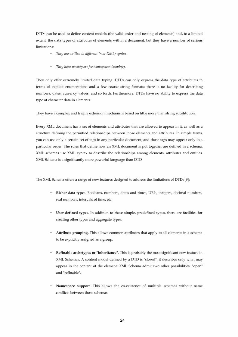
DTDs can be used to define content models (the valid order and nesting of elements) and, to a limited
extent, the data types of attributes of elements within a document, but they have a number of serious
limitations:
• They are written in different (non-XML) syntax.
• They have no support for namespaces (scoping).
They only offer extremely limited data typing. DTDs can only express the data type of attributes in
terms of explicit enumerations and a few coarse string formats; there is no facility for describing
numbers, dates, currency values, and so forth. Furthermore, DTDs have no ability to express the data
type of character data in elements.
They have a complex and fragile extension mechanism based on little more than string substitution.
Every XML document has a set of elements and attributes that are allowed to appear in it, as well as a
structure defining the permitted relationships between those elements and attributes. In simple terms,
you can use only a certain set of tags in any particular document, and those tags may appear only in a
particular order. The rules that define how an XML document is put together are defined in a schema.
XML schemas use XML syntax to describe the relationships among elements, attributes and entities.
XML Schema is a significantly more powerful language than DTD
The XML Schema offers a range of new features designed to address the limitations of DTDs [9]:
• Richer data types. Booleans, numbers, dates and times, URIs, integers, decimal numbers,
real numbers, intervals of time, etc.
• User defined types. In addition to these simple, predefined types, there are facilities for
creating other types and aggregate types.
• Attribute grouping. This allows common attributes that apply to all elements in a schema
to be explicitly assigned as a group.
• Refinable archetypes or "inheritance". This is probably the most significant new feature in
XML Schemas. A content model defined by a DTD is "closed": it describes only what may
appear in the content of the element. XML Schema admit two other possibilities: "open"
and "refinable".
• Namespace support. This allows the co-existence of multiple schemas without name
conflicts between those schemas.
24
3.2.2 XML Processing ImplementationsFor the manipulation of XML documents we have different approaches that can be used:
• DOM parsers
• SAX parsers
• XSL/XSLT
• Java XML frameworks
• JAXP
• JAXB
3.2.2.1 DOMThe DOM specification [11] defines a tree-based approach to navigating an XML document. In other
words, a DOM parser processes XML data and creates an object-oriented hierarchical representation of
the document that you can navigate at run-time.
The tree-based W3C DOM parser creates an internal tree based on the hierarchical structure of the XML
data. You can navigate and manipulate this tree from your software, and it stays in memory until you
release it. DOM uses functions that return parent and child nodes, giving you full access to the XML
data and providing the ability to interrogate and manipulate these nodes.
3.2.2.2 SAXThe SAX specification [12] defines an event-based approach whereby parsers scan through XML data,
calling handler functions whenever certain parts of the document (e.g., text nodes or processing
instructions) are found.
In SAX's event-based system, the parser doesn't create any internal representation of the document.
Instead, the parser calls handler functions when certain events (defined by the SAX specification) take
place. These events include the start and end of the document, finding a text node, finding child
elements, and hitting a malformed element.
SAX development is more challenging, because the API requires development of call-back functions
that handle the events. The design itself also can sometimes be less intuitive and modular. Using a SAX
parser may require you to store information in your own internal document representation if you need
to rescan or analyze the information—SAX provides no container for the document like the DOM tree
structure.
The strength of the SAX specification is that it can scan and parse gigabytes worth of XML documents
without hitting resource limits, because it does not try to create the DOM representation in memory.
Instead, it raises events that you can handle as you see fit. Because of this design, the SAX
implementation is generally faster and requires fewer resources. On the other hand, SAX code is
25

frequently complex, and the lack of a document representation leaves you with the challenge of
manipulating, serializing, and traversing the XML document.
3.2.2.3 XSL / XSLT
3.2.2.3.1 Extensible Stylesheet Language (XSL).XSL [10] enables you to present data in a paginated format. XSL supports the ability to apply
formatting rules to elements, to apply formatting rules to pages to add things like headers and footers,
and to render XML documents on various display technologies. XSL is typically used to publish
documents, often for printing, whereas XSLT is used to generate mark-up-oriented presentations such
as HTML or VoiceXML.
3.2.2.3.2 Extensible Stylesheet Language Transformations (XSLT)XSLT [10] enables you to transform data from one format to another. XSLT is often used to rearrange
the order of the content within an XML document so that it makes the most sense for display. XSLT is
effectively used to transform data documents into presentation documents, and then a user interface
technology such as XSL or a Cascading Style Sheet (CSS) is used to publish or display the data. It is
important to recognize that XSLT suffers from performance issues when compared to traditional
programming languages.
3.2.2.4 Java XML Frameworks
3.2.2.4.1 JAXB Java Architecture for XML Binding (JAXB) [13] provides an API and tools that automate the mapping
between XML documents and Java objects.
JAXB makes XML easy to use by compiling an XML schema into one or more Java classes. The
combination of both the schema and the generated java classes using the binding framework enable to
perform the following operations on an XML document:
• Unmarshal XML content into a set of Java technology-based objects representation
• Access, update and validate the Java representation against schema constraint using an
object method calls.
• Marshal the Java representation of the XML content into XML content
• JAXB provides a standard way of mapping between XML and Java code.
26

Figure 3.1 Data Binding Process
3.2.2.4.2 JAXP Java API for XML Processing (JAXP)The Java API for XML Processing (JAXP) [14] supports processing of XML documents using DOM,
SAX, and XSLT. JAXP enables applications to parse and transform XML documents independent of a
particular XML processing implementation.
3.2.2.5 Technology choiceBased of the described technologies for XML processing and manipulation, XSL/XSLT will be used for
XML content transformations in order to provide content to end-users in different multimodal ways.
JAXB will be used to generate a set of java classes that will bind application dependant Schema
definition. These classes it will provide ease of XML trees content creation through an object oriented
approach.
JAXP provides flexible mechanism for XML parsers swapping, any parser swap will depend on the
application needs, with the benefit of avoiding any code change, the technology's pluggable
architecture allows any XML- conformant parser to be used.
3.2.3 Multimodal PresentationMultimodal Interface is a multi channel delivery technology that simply adapts contents. The usability
of the same document on "poor" channels is very different from the usability on "rich" channels like the
web. It could probably be better if the user could use the different channels in the same moment to visit
27

the same service. Multimodal interfaces are interfaces where the interaction between the service and the
user is kept on using different channel simultaneously. For example a user can choose to complete a
form speaking, but can navigate to the next page using the pen given with its PDA.
3.2.3.1 WMLWireless Mark-up Language (WML) [15]is a mark-up language inherited from HTML. WML is based
on XML, so it is much stricter than HTML. WML is used to create pages that can be displayed in a WAP
browser (WAP phone). The Wireless Application Protocol (WAP) is an application communication
protocol used to access used to access services and information. This protocol is for handheld devices
such as mobile phones. This protocol uses WML for the creation of web applications for mobile devices.
3.2.3.2 HTMLThe Hyper Text Mark-up Language (HTML) [16]is a language for publishing hypertext on the World
Wide Web (www). A HTML files containing small mark-up tags that tell the Web browser how to
display the page.
3.2.3.3 XHTMLThe Extensible Hyper Text Mark-up Language (XHTML) [16] is a language that reproduces, subsets,
and extends HTML, reformulated in XML. XHTML document are XML-based, and ultimately are
designed to work in conjunction with XML-based user agents. XHTML is the successor of HTML.
3.2.3.4 VoiceXML and SALTSpeech interfaces enable users to interact with applications using their voices rather than through the
computer keyboard and monitor. Some of these interfaces can be voice mail or an IVR (Interactive Voice
Response) system at your bank. These applications prompt users for input, respond with request data,
and perform online tasks for users.
VoiceXML
Voice eXtensible Mark-up Language (VoiceXML) [17] is an XML-based Internet mark-up language for
developing speech interfaces. It is the language of what is called as “voice Web” which enables
telephone access to Internet-hosted content.
A VoiceXML dialog (the rough equivalent of an HTML page) describes prompts that an application
speaks to the user, defines and collects responses from the user, and describes program control flow.
28

Users access VoiceXML by dialling the phone number of the application. From the user’s point of view,
this phone number is the equivalent of a Web page’s URL. The user can call from any type phone,
including landline, cellular and satellite. VoiceXML language was decided to be novel rather than
extend HTML. This was because speech-enabled interfaces are so radically different from visual
presentations such as current Web browsers.
SALT
The Speech Application Language Tags (SALT) [18] enables voice interfaces definitions. SALT extends
existing mark-up languages such as HTML, XHTML, and XML. SALT enables voice access to
information from applications, and Web services from PCs, telephones, tablet PCs, and wireless voice
enabled personal digital assistants (PDAs).
3.3 J2EEThe Java 2 Platform, Enterprise Edition (J2EE) [19] defines the standard for developing multi-tier
enterprise applications. J2EE simplifies enterprise applications by basing them on standardized,
modular components, by providing a complete set of services to those components, and by handling
many details of application behaviour automatically, without complex programming.
The Java 2 Platform, Enterprise Edition, takes advantage of many features of the Java 2 Platform,
Standard Edition, such as "Write Once, Run Anywhere" portability, JDBC API for database access,
CORBA technology for interaction with existing enterprise resources, and a security model that protects
data even in internet applications. Building on this base, Java 2 Enterprise Edition adds full support for
Enterprise JavaBeans components, Java Servlets API, Java Server Pages TM and XML technology. The
J2EE standard includes complete specifications and compliance tests to ensure portability of
applications across the wide range of existing enterprise systems capable of supporting J2EE.
3.3.1 FiltersFilters, as they are called in the JavaServlet specification version 2.3 [20], are introduced as a new
component type. Filters basically are java classes that can dynamically intercept requests from a client
before they access a resource; manipulate this request and intercept responses from resources before
they are sent back to the client; and manipulate these responses if it is necessary.
The use of Filters in the architecture is important for several reasons:
• The first one and the most important for the presented architecture is that they are used to
catch Servlet’s request and response, and transform this response. This functionality gives
29

us the flexibility to provide content to the end-user in other formats rather than XHTML.
We can provide content in XML, VoiceXML and WML. In order to accommodate all these
different clients, there is usually a strong component of transformation or filtering; that in
this case is easily solved using Filters.
• The second one is that Filters provide a clean way of modularize the code. The code is
decoupled from the Servlet component and can be easily reused by another application.
Modularized code is easier to manage and debug. So at the end you are improving code
reuse.
• The third is that multiple Filters can be written and applied to the same URL pattern. This
allows us to create a decoupled Filter chaining, as the order of execution of these filters is
determined in the deployment descriptor file (web.xml).
• The fourth is that a Filter can be applied to different URL patterns, providing great
flexibility and extensibility to web applications.
3.3.1.1 Filter Life CycleLike Servlets, filters have a specification-defined lifecycle [21]:
• Filters are initialized by calling their init () method. The init () method is supplied with a
FilterConfig object that allows the filter to access initialization parameters as well as
reference to the ServletContext.
• The “doFilter ()” method of the filter is invoked during the request processing of a resource.
It is in the “doFilter ()” method that you can inspect the request, modify request headers,
modify the response, or skip the processing of the underlying resource altogether.
• The “destroy ()” method is called when the filter is destroyed.
30

Figure 3.2 Servlet Chaining
3.3.2 ServletsA Servlet is a Java programming language class used to [19] [21] extend the capabilities of servers that
host applications accessed via a request-response programming model. Although Servlets can respond
to any type of request, they are commonly used to extend the applications hosted by Web servers. For
such applications, Java Servlet technology defines HTTP-specific Servlet classes. The javax.servlet and
javax.servlet.http packages provide interfaces and classes for writing Servlets. All Servlets must
implement the Servlet interface, which defines life-cycle methods.
Java Servlet technology provides the following:
• Dynamic, user-oriented content.
• Scalability.
• Platform independence.
3.3.2.1 Servlet Life CycleThe life cycle of a Servlet is controlled by the container in which the Servlet has been deployed. When a
request is mapped to a Servlet, the container performs the following steps:
• If an instance of the Servlet does not exist, the Web container
• Loads the Servlet class.
• Creates an instance of the Servlet class.
• Initializes the Servlet instance by calling the init method.
• Invokes the service method, passing a request and response object.
31

• If the container needs to remove the Servlet, it finalizes the Servlet by calling the Servlet’s
destroy method.
3.4 Group CommunicationPeer-to-peer (P2P) computing (or peer-to-peer networking) means an environment where different
systems talk to each other in a distributed way, ideally without any central point, in opposition to
classical client-server model. In a P2P network peers act both as clients and servers, and can do things
like distributed computing, resource sharing, instant messaging, etcetera. Examples of P2P systems
include Napster, Gnutella, Freenet, ICQ, Jabber and JXTA.
3.4.1 JXTAJXTA [22] is an Open Network Programming platform for Peer-to-Peer computing, with a set of
protocols (XML-based) and standards that support peer-to-peer applications. The protocols defined in
the standard are also not rigidly defined, so their functionality can be extended to meet specific needs
or requirements.
JXTA is layered in three distinct tiers [22]:
• The core layer: Provides the basic mechanisms of peer groups, peer pipes and peer
monitoring; allowing peers to organize themselves into groups, logically connect to each
other through pipes and monitor and control the behaviour and activity of peers.
• The service layer: Builds on the very basic functionality of the core layer to add extra
functionality and facilitate application development. It provides functions that allow for
searching, sharing, indexing and caching code and content, and will also be used to
provide custom application-specific functions, such as secure messaging.
• The application layer: Applications use services to access the JXTA network and utilities.
This is the layer at which Sun expects the development community to develop most of the
code, built upon the core functionality and services provided by Sun. Users are intended to
interact directly with applications, which can use provided or 3-rd party service layer
functions.
The goals of JXTA are [22]:
“ - Operating system independence.
- Language independence.
- Providing services and infrastructures for P2P applications ”.
32

There are also conceptual goals. These goals include the following [22]:
“Provide mechanisms to allow peers to monitor each other and resources.
Provide an infrastructure for routing and communications between peers.
Communication with peers behind firewalls and other barriers is a key part of this goal.
Queries are distributed throughout the system
Distribute information about peers and network resources thought the network. group level.
Groups use authentication and credentials to control access and/or enable security
Use groups to organize peers and to give context to services and applications.”
3.4.1.1 JXTA Entities• Peers: A peer is any device that runs some/all JXTA Protocols.
• Peer Groups: A peer group is a collection of Peers that have agreed upon a common set of
rules to publish, share and access resources
• JXTA Pipes: JXTA pipe is the primary channel for JXTA communication Mechanism for
establishing unidirectional, asynchronous peer Communication.
• Messages: A message is the information transmitted using Pipes is packaged as messages,
which define a binary envelope to transfer either binary or XML.
• Advertisements: All JXTA network resources are represented by Advertisements as XML
documents.
3.4.1.2 JXTA Protocols
3.4.1.2.1 Peer Discovery ProtocolPeer Discovery Protocol (PDP) enables a peer to find advertisements on other peers and can be used to
find any of the peer, peer group, or advertisements. This protocol is the default discovery protocol for
all peer groups, including the World Peer Group. It is conceivable that someone might want to develop
a premium discovery mechanism that might or might not choose to leverage this default protocol, but
the inclusion of this default protocol means that all JXTA peers can understand each other at the very
basic level.
Peer discovery can be done with or without specifying a name for either the peer to be located or the
group to which peers belong. When no name is specified, all advertisements are returned.
33

3.4.1.2.2 Peer Resolver ProtocolPeer Resolver Protocol (PRP) enables a peer to send and receive generic queries to search for peers, peer
groups, pipes, and other information. Typically, this protocol is implemented only by those peers that
have access to data repositories and offer advanced search capabilities.
3.4.1.2.3 Peer Information ProtocolPeer Information Protocol (PIP) allows a peer to learn about the capabilities and status of any other peer.
For example, a ping message can be sent to see if a peer is alive. A query can also be sent regarding a
peer's properties where each property has a name and a value string.
3.4.1.2.4 Peer Membership ProtocolPeer Membership Protocol (PMP) allows a peer to obtain group membership requirements, to apply for
membership and receive a membership credential along with a full group advertisement, to update an
existing membership or application credential, and to cancel a membership or an application credential.
Authenticators and security credentials are used to provide the desired level of protection.
3.4.1.2.5 Pipe Binding ProtocolPipe Binding Protocol (PBP) allows a peer to bind a pipe advertisement to a pipe endpoint, thus
indicating where messages actually go over the pipe. In some sense, a pipe can be viewed as an
abstract, named message queue that supports a number of abstract operations such as create, open,
close, delete, send, and receive. Bind occurs during the open operation, whereas unbind occurs during
the close operation.
3.4.1.2.6 Endpoint Routing ProtocolEnd Routing Protocol (ERP) allows a peer to ask a peer router for available routes for sending a message
to a destination peer. For example, when two communicating peers are not directly connected to each
other, such as when they are not using the same network transport protocol or when they are separated
by firewalls or NATs, peer routers respond to queries with available route information--that is, a list of
gateways along the route. Any peer can decide to become a peer router by implementing the Peer
Endpoint Protocol.
34

3.4.2 JGroupsJGroups is a toolkit for reliable multicast communication. It can be used to create groups of processes
whose members can send messages to each other, in other words, helps us to create p2p and
client/server applications. The main features of JGroups include:
• Group creation and deletion.
• Group’s members can be spread across LANs or WANs.
• Joining and leaving of groups.
• Membership detection and notification about joined/left/crashed members.
• Detection and removal of crashed members.
• Sending and receiving of member-to-group messages (point-to-multipoint).
• Sending and receiving of member-to-member messages (point-to-point).
JGroups consists of three well defined parts:
• The Channel API used to build reliable group communication applications.
• The Building Blocks which are layered on top of the channel and provide higher
abstraction level.
• The Protocol Stack.
3.4.2.1 ChannelChannels are used to join a group and send messages across the network. A channel is then the atomic
interaction unit that represents the handle to the communication group. Channels allow us to send and
receive messages to / from all other peers in the group. Every peer in the group knows who the other
members are.
3.4.2.2 Building BlocksJGroups offers Building Blocks that provide more sophisticated APIs on top of a Channel. Building
Blocks are intended to save application time development as they already provide the functionality,
avoiding us to write such code.
3.4.2.3 Flexible Protocol StackThe most powerful feature of JGroups is its flexible protocol stack, which allows developers to adapt it
to exactly match their application requirements and network characteristics. The benefit of this is that
you only pay for what you use. By mixing and matching mini-protocols, various differing application
requirements can be satisfied. The composition of protocols to be used is defined by the creator of the
Channel. Protocols are layered in a bidirectional stack.
35

Some of the protocols provided by JGroups are:
• Transport protocols: UDP (IP Multicast), TCP, JMS
• Fragmentation of large messages.
• Reliable unicast and multicast message transmission.
• Lost messages are retransmitted
• Failure detection, crashed members are excluded from the membership
• Ordering protocols: Atomic (all-or-none message delivery), FIFO, Causal, Total Ordering
(sequencer or token based).
• Membership service.
• Encryption.
• State Transfer.
3.4.2.4 JGroups Successful StoriesBased on the benefits above described that JGroups can provide to the architecture implementation,
there are a set of successful projects that have definitely influenced in the choice of this toolkit. The most
relevant are:
• Jboss (Clustering of Enterprise Java Beans).
• Jtrix (Adaptive, scalable, distributed applications).
• GroupPac (An open source implementation of the Fault-Tolerant CORBA specification).
• Tomcat HTTP session replication.
• JOnAS clustering (Java Open Application Server) is an Open-Source / LGPL
implementation of J2EE [TM].
• GCT - Group Communication Toolkit in .NET.
3.4.3 JGroups Vs JXTABoth thechnologies allow group communications but JXTA does not provide features such reliable
multicast, failure detection, ordering protocols, state transfert. The absence of these features in JXTA
does this technology not a desirable choice as middleware.
36

3.5 Aspect Oriented Software Development Aspect-Oriented Programming (AOP) is a new programming paradigm developed at Xerox PARC
for modularizing complex software systems. As an extension to other software development
paradigms, such as object-oriented development, it allows to capture and modularize concerns that
crosscut a software system in so-called aspects. Aspects are constructs that can be identified and
manipulated throughout the development process.
The OOP paradigm can not address the localization of concerns that do not naturally fit into a single
component, such crosscutting concerns are usually spread through multiple components, with the
consequent code tangling and scattering.
[23]“An aspect is, by definition, modular units that cross-cut the structure of other
units. An aspect is similar to a class by having a type, it can extend classes and other
aspects, it can be abstract or concrete and have fields, methods, and types as
members. It encapsulates behaviours that affect multiple classes into reusable
modules”.
3.5.1 AspectJAspectJ is an aspect-oriented extension to Java. Its language specification defines various constructs and
their semantics in order to support aspect-oriented software development.
AspectJ adds a number of additional concepts to the Java language: (i) joinpoints, (ii) pointcuts, (iii)
advices and (iv) aspects.
3.5.1.1 Joinpoint ModelThe joinpoint model makes it possible the definition of crosscutting concerns . Joinpoints are well-
defined points in the execution of the program such as method calls, method execution, a conditional
check or an assignment. They are predefined and also have a context associated with them, meaning
that it is necessary to specify what joinpoint is to take action when defining pointcuts.
• Pointcuts (or pointcut designators) are program structures that allow the definition of
joinpoints in the execution of a program. Pointcuts let as well “expose context at the joinpoint
to and advice implementation”
• Advice is the code that implements the additional behaviour. This code is executed when a
joinpoint is reached. AspectJ provides three different advices; before advice, after advice, and
around advice.
37

• Aspects are AspectJ’s units of modularisation and encapsulation. The purpose of an Aspect
is the definition and implementation of crosscutting concerns, Class definition. Aspects
provide as well all the features that classes have in the OOP paradigm (instantiation,
attributes definition, operations, inheritance). Aspects provide non-pervasive extension
mechanism for enhancing the features and behaviour of a Class definition. Aspects can be
considered an evolution/extension of Classes as they provide their same features plus the
weaving rules (a pointcut and an advice put together).
38

Chapter 4
Architecture Design
The architecture to be designed has to address a number of requirements that have been collected from
the KAREN specifications. Following the requirements the design falls into a very specific architecture
for collecting and disseminating car parking data with a consequent drawback, any other traffic data
types have diverse and different requirements and constraints and may not be handled correctly by the
system.
So thus, the architecture has been designed very carefully in order to fulfil the collected requirements
from KAREN (see below 4.1, page 41) and to provide the flexibility and extensibility required for future
collection and dissemination of any other traffic data types.
From a pure and a theoretical point of view, the architecture falls into the Distributed System area, these
systems claim for a number of functional requirements that have to be particularly addressed by our
solution. These are the followings:
• Availability: [24]Availability is the degree to which a system suffers degradation or
interruption in its service as a consequence of failures of one or more of its parts.
• Reliability: [24]Reliability of a system is the probability of not making mistakes.
• Fault-Tolerance: [24]It is a measure of the reliability and availability of the system. It is the
ability to continue providing its functionality even when a hardware failure occurs. A
fault-tolerant system is designed from the ground up for reliability by building multiples
of all critical components, such as CPUs, memories, disks and power supplies into the
same computer. In the event one component fails, another takes over without skipping a
beat. Many systems are designed to recover from a failure by detecting the failed
component and switching to another computer system. These systems, although
sometimes called fault tolerant, are more widely known as "high availability" systems,
requiring that the software resubmits the job when the second system is available.
• Scalability: [24]We define scalability as the ability of a system of how well it will work
when we increase the number of nodes to handle load increase. This definition can be used
to measure how well an algorithm works when the size of the problem increases.
• Performance:[24] We define performance as the ability to perform workload distribution.
39

There are some other terms we use in the description of the architecture:
• Object: [24]An object, in object-oriented programming “fashion”, as a unique instance of a
data structure defined according to the template provided by its class. Each object has its
own values for the variables belonging to its class and can respond to the messages
(methods) defined by its class. So an object has a state at any given time and provides a
specific behaviour. So far we can extrapolate this concept to the real world for every
particular thing.
• Server: [24]A program which provides some service to other (client) programs. The
connection between client and server is normally by means of message passing, often over
a network, and uses some protocol to encode the client's requests and the server's
responses. The server may run continuously, waiting for requests to arrive.
• Proxy-Server: [24]A proxy server is a process providing a cache of items available on other
servers which are presumably slower or more expensive to access. This term is used
particularly for a World-Wide Web server which accepts URLs with a special prefix. When
it receives a request for such a URL, it strips off the prefix and looks for the resulting URL
in its local cache. If found, it returns the object immediately, otherwise it fetches it from the
remote server, saves a copy in the cache and returns it to the requester. The cache will
usually have an expiration algorithm.
• Protocol: [24]A set of formal rules describing how to transmit data, especially across a
network. Low level protocols define the electrical and physical standards to be observed,
bit- and byte-ordering and the transmission and error detection and correction of the bit
stream. High level protocols deal with the data formatting, including the syntax of
messages, the terminal to computer dialogue, character sets, sequencing of messages etc.
• Client-Server: (see above 3.1.1, page 21)
• Distributed-System: (see above 3.1, page 21)
• Failover: [24]We define failover as the ability of the system to overcome the failure of
another system transparently. Providing the same service to the end-user, without its
perception that failure has occurred.
40

4.1 Collected Car Parking RequirementsThe requirements for the car parking prototype have been collected from the actual specifications of
KAREN [25]. The scope of the car parking service is given by the following:
Functional Area 3 Manage Traffic [25]
“This Area shall provide functionality enabling the management of traffic in urban and inter-
urban environments. Functionality shall be included to detect and manage the impact of
incidents, produce and implement demand management strategies, monitor car park
occupancies and provide road transport planning. Links shall be provided to the Provide
Safety and Emergency Facilities and Manage Public Transport Areas so that their vehicles
are given priority through the road network and to enable assistance to be provided in the
implementation of incident and demand management strategies. The External Service
Provider terminator shall be sent data about traffic conditions and strategies.”
Low Level Function 3.1.1.2 Monitor Urban Car Park Occupation [25]
Overview
“This Low Level Function shall collect traffic data from the entrances and exits of car parks in
the urban road network, as well as from the spaces themselves. This data shall be provided as
raw input by sensors within the Function that are capable of detecting the passage and
presence of all types of road vehicle, from bicycles to heavy freight vehicles. The data from the
entrances and exits shall be processed to provide actual traffic count data, i.e. numbers of
vehicles, at the entrances and exits of each car park. The resulting data shall be passed to other
Functions for collation, use in urban traffic control and for providing traveller information.
The data from the spaces shall be used to determine whether a vehicle has exceeded the time
that it can occupy a space. When this occurs, the information shall be sent to the Provide
Support for Law Enforcement Area for further processing.”
Functional Requirements [25]
“The presence of both of the trigger input data flows shall be continuously monitored
The analogue data representing the raw traffic flow data obtained in (a) from the second
trigger input data flow shall be converted into digital data that separately shows the numbers
of vehicles entering and leaving the car park
The data for each car park in the urban road network obtained in (b) shall be kept separate and
split into vehicles entering and leaving
All the trigger output data flows except the last shall be used to send the data in (c) to the
urban road network traffic control and data management Functions and to the Provide
Traveller Journey Assistance Area
41

The analogue data representing the presence of a vehicle in a car park space obtained from the
first trigger input data flow shall be analysed to determine how long the vehicle has been
occupying the space and the identity of the vehicle
The length of stay obtained in (e) shall be compared with the maximum continuously allowed
time obtained from the third trigger input data flow
When the actual length of stay exceeds the permitted value, the identity of the vehicle and
details of the length of stay violation shall be sent to the Provide Support for Lay Enforcement
area using the fifth trigger output data flow.”
User needs [25]
“7.1.11.1 The system shall be able to monitor the current usage of the parking facilities.”
“7.3.0.2 The system shall receive up-to-date information on those factors that will influence
the demand management strategy, e.g. traffic levels, car park usage, PT usage, fares, tolls,
etc.”
4.2 Layered Architecture DesignIn order to commit all the requirements, a multi-tier architecture has being devised. The different
architectural components will be described by their roles, and do not mean to imply that they are
necessarily implemented by distinct processes or hardware. The model or the architecture to be
described involves:
• Presentation Tier
• Business Tier
• Proxy Tier
• Connector Tier
The architecture is based in the Model View Controller (MVC) pattern [26], where MVC states that the
core business process should not assume anything about the clients. Instead of a browser, PDA, WAP,
another application or any other back office system may well invoke it. The component that deals
between the business logic and view elements is to be assigned to a dedicated component called the
controller.
J2EE's architecture follows a MVC approach, and naturally demarcates business logic tier from
presentation logic tier. Controllers can be placed in either of these tiers or both. So thus, J2EE provides us
a place where to place reusable business logic components.
42

Figure 4.1Multi-tiered Architecture
4.2.1 Presentation TierRepresents a single-point-of-entry to the application, it provides a transparent “service-invocation”
mechanism for end-users. Each end-user's request is firstly handled by the Front-Controller Component.
This component acts as single point of entry and communicates with the business logic by message
passing.
43

When the Business tier returns a response to the Presentation tier, for a particular end-user's request, it is
handled by the View component. The responsibility of this component is to provide the specific view for
that particular end-user's request.
So thus the Presentation tier provides a multimodal interface to end-users. The resulting information to
be returned is plain XML, thereby it can be adapted and formatted for different output channels in
different ways such as HTML, WML, VoiceXML, XML or any other format required.
4.2.2 Business TierThe Business tier provides the business logic of the application. It provides a clear interface to the
Presentation tier, as this tier acts as a Facade [26]. Using a Facade pattern, the complexity of interactions
between the business objects (that participate in the workflow to provide the required end-user
functionality) is encapsulated. So the number of exposed Business objects to the Presentation tier is
reduced. This provides more flexibility, manageability, extensibility and ease maintainability of the
code.
The business logic components are responsible for dealing with the underlying tier. This interaction
requires the use of a third party middleware that provides transparent way for retrieving traffic
information.
This tier is as well responsible of translating / providing data to the upper tier in plain XML format.
The reasons of returning XML instead of Java Data Objects are: (i) XML is a system-independent
standard and (ii) mainly because separates content from presentation. This allows the architecture to
expose a neutral interface to any other components. Any other service can be added on top of the
business tier easily
4.2.3 Proxy TierThe main function of this tier is to provide the to the Business tier “fresh”, or up-to-date traffic parking
data. For this purpose an algorithm for “disseminating dynamic data” (see below 4.3.2, page 46 ) has been
implemented.
In order to obtain a service that is scalable, fault tolerant, and high available, a clustered environment has
been devised by the use of a reliable group communications toolkit (JGroups). This toolkit encapsulates
the replication process of the cached information among the different proxy-serves that will constitute
the cluster. The toolkit provides a transparent mechanism for retrieving and updating data contents in
the cache.
44

There are some crucial concerns derived from the use of a clustered architecture such (i) the Data
Replication Protocol to be implemented, (ii) the Membership Service used, (iii) the Fail-over mechanism
addressed (see below 4.4, page 52).
4.2.4 Connector TierThe Connector tier is responsible of gathering or receiving traffic parking data. As the link with the
traffic parking data source could not be set up on time, due bureaucratic issues with the Dublin City
Council; this tier will generate as well random parking data.
The generated data will be pushed to the upper tier based on the implemented algorithm (see below
4.3.2, page 46). For a better understanding of the implementation, it is important to clarify that the
algorithm is in two different components as it is a merge between two strategies.
4.3 Caching algorithms for updating dataWithin the proposed system architecture there are two different caching systems with different
purposes that have been already described <reefer that section>. Data caching is a common strategy for
reducing the access time to remote sources or, improving the performance by putting into memory data
stored in any other location that requires more processing time to access.
The algorithms implemented are two:
• Push Algorithm
• Lazy Pull and Push Algorithm
4.3.1 Push Algorithm.The algorithm implemented is a push-based approach. Every time data stored in the cache is accessed, a
check for update is done. If the data in memory has a timestamp that is earlier in time than the data in
the source, this means that the data has changed at the source and then has to be reloaded into the
cache.
Formally, if T ij is the time stamp of the data Di at time T j , and T ik is the time stamp of the
data Di at time T k , and T kT j that means T j earlier than T k . If T ijT ik means that
data has changed and then has to be updated from the source.
45

4.3.2 Lazy Pull and Push Algorithm Often [27] large data collections have to be updated and network or computational resources can be
limited. Considering traffic sensor networks that often operate over low-bandwidth links, since
thousands of sensors may be involved, sensor readings may change very frequently due to rapidly
changing traffic conditions and the available bandwidth is low and expensive. In these cases is not
practical to propagate every new sensor measure to a central repository every time it has changed.
Although there are other solutions such as sensor fusion, where sensor readings are collected in a join
point and after a while transmitted to the central repository. In environments where it is not possible to
propagate rapid data changes due to insufficient network or computational resources, synchronizing
data between the source and the cache may be not possible. The solution is to allow stale caching, in
which the cache is permitted to store stale, or out-to-date, copies of source data. But traffic data can
have strong time constraints and have to be synchronized almost in real time. The proposed solution is
based in a best-effort synchronization strategy, where some policy or rules determine when cached data
has to be updated or refreshed. In most refresh scheduling policies [28] the cache plays the main role:
updates are implemented by pushing data to the clients or polling the sources. Best-effort
synchronization depends on how frequently source data objects change; in stale caching the state of an
object can be different from the source, this difference is called divergence and can be measured using
some metrics [27] such us Boolean freshness (up-to-date or not), number of changes since refresh, or
value deviation. Caching efforts in the World Wide Web [29] fall into two categories:
• Weak consistency mechanisms, where cached data can be out of-sync with servers
• Strong consistency mechanisms, where cached data is always up-to-date with servers.
Mostly of web-cache systems provide weak consistency of the data, so it might be possible to return to
the user a stale copy of the object. Weak consistency strategies are mostly associated with Time-To-Live
(TTL) [30] or Time-To-Refresh (TTR) [27], in which the client receives the cached object if the TTL or the
TTR has not expired. Weak consistency is not satisfactory in terms of large TTL, especially if we talk
about Traffic Information.
For the scope of the dissertation, parking information has not a big time constraint, but for other kind of
traffic information such as congestion information, emergency, accident rescue services information.
Then TTL of the cached data represents a strong constraint in the system.
46

Mechanisms such us replication, client validation, polling-every-time [31] and server invalidation,
where the server sends invalidation messages to all clients when an object is modified provide strong
consistency of the cached data. A polling-every-time strategy is based on sending an If-modified-since
request to the server at every scheduled cache hit. On the contrary an invalidation strategy is based on
sending invalidation messages to the cache every time an object has changed. Studies have
demonstrated that strong consistency strategies do not necessarily consume more network resources
than weak consistency mechanisms [30]. The following question arises
- How can strong consistency be achieved for cached traffic data, minimizing the possible network overhead
(caused by sending messages across the network)? -
4.3.2.1 Lazy Pull and Push Algorithm DefinitionThe algorithm implemented tries to minimize the sum of the divergence values for each source data
object and its replica in the cache, and as well as reduce the traffic network. The proposed and
implemented solution is based on a modified push-pull approach, where pull is done in a lazy manner,
so thus, updates are done when a user requests an object in the cache and a condition is violated.
An important issue in the algorithm is the temporal coherency requirement (tcr) associated with time-
varying traffic data; this depends on the nature of the data and user tolerances. As the user will obtain
data from the cache rather than from the source, for this particular scenario, the cache must track
dynamically changing data so as to provide users with temporally coherent information. We will
assume that the user specifies a tcr for a data traffic type. Then tcr denotes the maximum permissible
deviation from the value at the source, and thus, constitutes the user-specified tolerance. The tcr for our
purposes is specified in units of time (e.g., the traffic data should never be out-of-sync by more than 2
minutes). To maintain coherence, each data object in the repository must be refreshed in such a way
that the specified user's coherency requirements are maintained.
Formally:
S t Denotes the reception time of the data object at the source.
P t Denotes the reception time of the propagated data object at the proxy server.
U t Denotes the reception time of the cached data object at the user side.
47

Figure 4.2 Temporal Coherency Problem
Then, to maintain temporal coherence, we should have ∣U t −S t ∣tcr |. The effectiveness the
cache can be quantified using a metric referred to as fidelity.
"The fidelity of a data item is the degree to which a user's temporal coherence needs are met.
We define the fidelity, f, observed by a user to be the total length of time that the above
inequality holds (normalized by the total length of the observations)." [32] [33]
Traffic data can have different temporal coherency requirements due to their nature. Car parking data
do not have the same constraints as congestion data, emergency data, etc. For every particular traffic
data type we will have a tcr that in our case will be determined by the Dublin City Council. The value of
tcr means the maximum time an object can be desynchronized from the source, this constitutes the user
tolerance.
A Pull-based strategy does not offer high fidelity when data changes rapidly or when the coherency
requirements are strong. This strategy imposes a large communication overhead (in terms of the
number of messages exchanged).
A Push-based strategy offers on the contrary high fidelity for rapidly changing data and/or strong
coherency requirements. However, the overhead of the number of push-based connections it has to be
considered. This approach can be less flexible to failures due to its stateful nature.
Let’s assume the proxy-server pulls data from the source-server using an algorithm to decide an
adaptive TTR value. After initial synchronization, the source server runs the algorithm. Under this
circumstances our source server is aware when the end-user will be polling next, based on the
calculated TTR. With this, whenever the source server realizes that the end-user must be notified of a
new data value, the source server pushes data to the proxy-server if and only if determines it has to do
it.
48

The algorithm devised and implemented in [32] , will be adapted it to satisfy traffic data needs. Using a
Push-and-Pull algorithm we can take advantage of both approaches. The tuning of the various
parameters of the algorithm is going to determine the degree to which push and pull strategies are
used.
4.3.2.1.1 Lazy PullThe Lazy Pull-based strategy is based on the calculation of an adaptive TTR. The proxy uses a lazy
approach, only when the TTR of the cached data has expired and a user requests that data from the
cache, a request for update is sent to the source server; with this we avoid aggressive polling of the
server. TTR is adaptive [32], and to achieve this it has to take in to account the following:
• Static range, so that TTR is bounded to a maximum and a minimum value and their values
are not set too high or too low.
• The most rapid changes occurred so far.
• The most recent changes to the polled data.
The value of TTR is calculated as:
MAX TTRmin , MIN TTRmax , a∗TTRmr1−a∗TTRdyn
Where:
[TTRmin ,TTRmax ] is the bounded range of values for TTR.
TTRmin is bounded to 0 and TTRmax is bounded to tcr in the system.
TTRmr is the TTR value used so far.
TTRdyn is the learning TTR estimate based on the assumption that the dynamics of the last
few changes (the last 2 changes in the case of the formula) are likely to be reflective of changes
in the near future.
TTRdyn=w∗TTRestimate1−w ∗TTRlatest
TTRestimate=TTRlatest /∣Dlatest−D penultimate∣∗tcr
49

If the recent rate of change persists, TTRestimate ensures that changes which are greater than or equal
to tcr are not missed.
0.5≤w1 Weights the preference given to recent and old changes, as closer w is from 0.5
we give more relevance to new data updates than older ones. The default value is 0.5.
0≤a1 It is a parameter of the algorithm and can be adjusted dynamically depending on
the fidelity desired. A higher fidelity requires a higher value of a .
4.3.2.1.2 PushThe Push-based strategy is based [32] in the assumption that the server is aware when the client might
be polling next. With this, the server pushes data to the proxy whenever he thinks the client must be
updated. The way the server decides when the data has to be pushed is based on T predict . The server
computes for every single data, the difference of the last two pulls ( diff ) and assumes that the next
pull will occur after a similar delay.
diff =T lastrequest−T penultimate
T predict=T lastrequestdiff
If the value of diff is less than tcr, T predict is calculated as T predict=T latestrequesttcr ; else it is
considered as T predict=T latestrequestdiff . So thus if the proxy requests some data and T predict has
not expired, the server does not have to push the data unless diff tcr and T latestrequesttcr has
expired. If the data object at the source differs from the previous pushed value, although T predict has
not expired, the data will be pushed if T latestrequesttcr has expired. The data will be pushed
anyway when T predict has expired and no request have been received or the data has not changed
within that time interval. The value initial value of T predict will be T predict=T actualtimetcr as the
server has no history of previous requests. The advantages of this are that we avoid pushing data when
is not required, so thus, we consume less bandwidth and less messages are sent across the network.
This approach makes the server to be stateful and it has to keep track of the latest requests; this can be a
drawback if the server crashes, but can be easily overcome considering that the server manages a
lightweight session only keeps a little state. When the server starts up again, reinitialises T predict time
for every data as T predict=T systemtimetcr
50

4.3.2.2 Targeting Traffic DataAfter realizing how both strategies work, we have to consider that traffic data demand different
behaviour of the algorithm. Depending on the data we have to collect and disseminate, we will have to
consider different strategies in order to provide strong consistency of the data and meet the tcr. So thus
the algorithm has to enable us to balance between a Push and a Pull strategy.
We can handle this by modifying the formula that calculates T predict . If an end-user does not pull for
data when it is expected by the source-server, it will wait till pushes a small amount of time [32] by
adding diff to T predict So if =0 , the algorithm goes to a push strategy; if the value of is
large then the algorithm performs as a pull approach.
Tuning the value of we can provide an algorithm that performs both push and pull capabilities in
order to meet the end-user's tcr; as well as the number of messages sent across the network.
4.3.2.3 Possible OverheadsBoth push and pull strategies incur in some (i) computational and (ii) communication overheads [32].
4.3.2.3.1 Communication overheadsUsing a push strategy, the number of messages sent over the network is equal to the number of times a
proxy-server receives data changes. So that tcr is maintained. Using multicast a single push message
will server a number of proxy-servers interested in the same data.
A pull strategy requires two messages, a request and a response, per poll. In this approach a proxy-
server polls the source server based on the estimated TTR (based on how frequently the data is
changing). If the traffic data changes at slow rate, the proxy-server might poll more frequently than
necessary. Hence a pull-based strategy might cause higher load on the network.
However, a push strategy might push data to the proxy-server, and this data is not required by the end-
user. Thus the push strategy might send unnecessary messages.
4.3.2.3.2 Computational overheadsA pull strategy obliges the source server to deal with every request sent by the proxy-server. The
source-server has responded with the latest value of the requested data object. On the other hand, using
a push strategy, the source-server will push changes to the proxy-servers; this means that the source-
51

server has to check if the tcr has been violated for every received / collected data. This is directly
proportional to the arrival of new data and the tcr assigned. Although the frequency of the changes can
vary in time, it is clear that a push strategy has a higher computational overload. This is under the
assumption that the generation of new traffic data is higher than the generation of end-user requests.
4.3.2.4 Performance Issues It may be problems of synchronization between the server and the end-user that have to be faced. These
problems are a consequence of network delays and processing load imposed by running the algorithm
for every particular data.
When updating a cached data objects, the number of possible pull messages sent across the network can
be minimized. When several users request the same cached data, and the TTR value for that particular
cached object has expired. Only one request will be sent to the source server, so the computational
overhead is as well minimized (because the source server only has to compute one message per data
object per proxy-server).
Looking to the source server side, several requests of same data can be handled from different proxy
servers as only one. When those requests occur in closer instants of time, the solution in order to
minimize the number of responses is quite simple. The data source server keeps a little state for every
single data in the cache. The state is constituted by T latestrequest and diff . Such data is used to
calculate T predict in order to control when the traffic data has to be pushed to the replicated caches
via a multicast protocol. In conclusion, the data source server only serves a request from a proxy server
if T latestrequesttcr has expired.
4.4 Clustering of Proxy-Servers[34]One of the characteristics of the implemented architecture is that, web/Servlet containers and both
caching subsystems can be fully distributed, thereby ensuring scalability, reliability, fault tolerance, and
the full use of multiple machines while avoiding bottlenecks. There several ways to provide scalability
at the Web tier. The first way to scale up the number of concurrent sessions handled by the service is to
add resources to the server. These resources usually are hardware components such us memory, disk
space (storage resources), and CPU (computing resource).
The drawbacks to this approach are the hard limit imposed by the limits of the hardware expansion
(number of available CPU slots) and the cost of the CPUs. These constraints limit the number of end-
user sessions that we can handle on the Web tier with a single-server solution. In fact, the single-server
solution is often not a robust solution because of its single point of failure. If the server crashes, the
service will not be available while the server is down, so thus this solution is not suitable for high-
52

available services such ours. There are partial solutions to this problem such providing shadow servers
that takeover when the master server fails; but as well this solution can be quite costly.
There is a viable and suitable solution to the scalability problem that matches the requirements.
Clustering enables a group of (typically loosely coupled) servers to operate logically as a single server,
providing a single system image. The advantages of clustering include:
• High service availability if multiple servers in the cluster handle the same service.
• Load balancing by diverting requests to the least loaded server that provides the same
service.
• Single point of failure avoidance, as more than one server can takeover the failure of one of
the other servers that provide the same service.
Recently, clustering has "hit the mainstream" [34] due to a number of converging factors:
[34]“J2EE Web tier containers (application servers) technology is finally maturing, and their
state management and operational models are well specified and understood. By replicating
the state of Web tier containers across a cluster of servers, you can implement a scalable
service solution.”
[34]“The cost of PC-based servers is at low levels (with CPU power per server continuing to
increase), making clustering more affordable than ever.”
[34]“High-speed LAN-based interconnects are widely available and inexpensive.”
[34]“The adoption of the open source Linux operating system enables even custom clustering
solutions to be implemented, maintained, and sustained in a non-proprietary manner.”
But the hardware only is half of the solution [35]. A way to provide all this is to build a type of parallel
or distributed processing system, let say a collection of interconnected stand-alone application servers
working together as a single, integrated computing resource. Such architecture can then provide a cost-
effective way to gain in high performance, expandability and scalability, high throughput, high
availability.
With the proposed clustering architecture, we provide a system as a unified resource, so thus it posses a
Single System Image (SSI). This SSI is supported by using a communication middleware for creating
cluster solutions; in this case we are talking about JGroups (see above 3.4.2, page 35).
53

4.4.1 Load Balancing at the web layerBy the use of a cluster of servers the load can be distributed among them. This provides the flexibility of
building up distributed systems that support load balancing along with fault tolerance. With load
balancing the architecture obtains the ability of distributing end-user’s service requests over multiple
servers. This allows effective and efficient use of the servers within the cluster, avoiding scalability
bottlenecks.
4.4.1.1 Load Balancing Algorithms and MechanismsA load balancing algorithm [36] [37]is used to decide which server should handle a given 'unit of
work'. Such a unit of work will be a user request or a user session. Common algorithms include static
algorithms like:
• Round Robin.
• Random.
• Weight-based.
Dynamic algorithms like:
• Network response time.
• Server load-based.
• User-specific algorithms.
By using load balancing we can distribute service request over the group of servers that are part of the
cluster at runtime, and therefore handle more requests than using a single server. When applied these
strategies to the Internet, this principle usually means that a request can be processed by any one of
several mirrored web servers (thus any replica in a cluster of web servers). Including a high availability
algorithm to the cluster we can assure that the server to which it forwards the request is available.
Adding a failover mechanism allows the cluster to switch/forward the request to another server in the
cluster without a disruption in the service.
The Load Balancer used is the Resin server implementation. This server includes a balancer component
(implemented as a Servlet) which will balance end-user's requests to the proxy-server cluster. Because
the load balancer is implemented as a Servlet, this configuration represents the most flexible choice.
Load Balancing increases reliability in the system, the Resin server will automatically try another
server if one fails. As an illustration, if one web server has a 1% chance of failure, two web servers
balanced by Resin have a 0.01% chance of simultaneous failure.
54

Figure 4.3 Load Balancing Mechanism
4.4.1.2 Fault Tolerance Another goal of the proposed architecture is to provide the ability to make services available in the
event of failure of individual servers or processes, that is, fault tolerance. At the level of the Web Layer,
requests in progress to a server/process that fail may be lost, but future requests are sent to another
server/process to prevent system failure, thereby ensuring high availability. In conclusion, what we are
trying to avoid is to have a single, any server, process or other component (for example, a network
component) that prevents the overall system from working if that server or process fails. The idea
behind fault tolerance is to use reasonable replicas (within clusters) to prevent single points of failure.
Failover is the algorithm or process used to keep the system operational when a failure of one replica
occurs. The load for a failed replica must be redirected to a working replica. Fault Tolerance usually
means "up to a certain degree", for example, session loss for a certain number of user connections or
similar. Fault tolerant systems avoid single points of failure.
4.4.2 Cache ReplicationThe objective of this architectural component is to achieve two important paradigms [38] membership
and multicast communication. These two paradigms exist under these two domains: fault-tolerant
applications (replicated services), and data dissemination applications.
Both domains are applicable to the architecture and determine the objective of providing replication of,
in this case, traffic data. Replication is maintaining copies of data at multiple computers. It is a key to
55

providing “high availability, fault tolerance and enhance performance” in the system architecture. As data
are replicated transparently among several failure-independent proxy servers, and their work-load is
shared due to the load balancing mechanism. A user can request traffic data in a transparent way and
he will be redirected to any alternative proxy server that is available within the cluster.
Network partitions militate against high availability, as high available data is not necessarily strictly
correct data. It might be out of date in one of the partitions. The correctness concerns the freshness of
data supplied to the users, this is the case of Intelligent Transportation Systems where correct data are
needed in short time scales. Our system has to manage the coordination of the proxy-serves precisely;
to maintain the correctness guaranties of the traffic data in case of failures, which may occur at any
time.
The front-end, using a load balancing mechanisms, has to communicate user's requests to one of the
clustered proxy-servers by message passing, rather than forcing the client to do this itself explicitly.
This is the way for making replication transparent.
4.4.2.1 Managing replicated data.As a key to achieve fault-tolerance, the use of group communication is an important approach and
particularly useful. The source data in this case, car parking information, can be any other kind. Each
logical object is implemented by a collection of physical copies called replicas. The replicas are stored in
the distributed caches within the cluster. The replicas of a given data, might have not received updates.
In order to provide a solution that handles failures and help us to keep consistent data among the
several proxy servers we will use group communication.
The architecture introduces two level of caching subsystems. Both subsystems have different purposes
and constraints. In order to fit their requirements two different strategies have been designed. Before a
further explanation of these strategies, it is important to clarify the group communication basis which
both strategies are built onto.
4.4.2.1.1 Group communication for data replicationGroup communication has to be handled within the group of servers; this is done by multicasting
messages to the group. The group, in this case, is the logical container for a number of proxy-servers
that are addressed as a single entity (the group). But in order to manage the dynamic membership of
the group, as servers can join, leave, fail; there is also needed a group membership service to manage the
dynamic membership of the group. Such a service has to [37]:
“Provide an interface for group membership changes.”
“Provide a failure detector.”
56

“Provide a notification mechanism to the group members of the changes.”
“Perform group address expansion, extend 1-1 to 1-n communications.”
Figure 4.4 Group Communication
Reliable multicast communication
We will use IP multicast, [37] the use of a single multicast operation instead of multiple send operations
enables the implementation to be efficient and allows it to provide stronger delivery guarantees than
would otherwise be possible. [39] The advantage of multicast is manifested by combining together
overlap requests to a single transmission. This way the server load and bandwidth decreases
dramatically since all overlapped users appear almost as a single user. Studies have been done and
proved that [40] saves extra delay imposed by the TCP flow control mechanism, which adapts to a
57

congested network. One of the reasons for the degradation in performance seen by clients at peak times
is the congestion in core links. The closer the link is to the server, the more congested it can become.
Although the TCP congestion control mechanism tries to limit the effect of such peak times, by
exhibiting a social behaviour, the effect on both the site and the client is big. The site retransmits an
extensive amount of packets until the TCP slow start mechanism takes effect, while the client
experiences degradation in performance. The use of multicast mechanism for the delivery of hot data
reduces both the traffic on core links, and the load on the server.
By adding reliability to the multicast protocol [36] we assure that all the members of the group will
receive the message, but reliability affects the performance due to the possible retransmission of
messages that will increase the latency.
4.4.2.2 Replication of data at the Web Tier
4.4.2.2.1 Data Replication in the Presentation TierThe use of XSL/Transformations for transforming the output XML into different representations has a
performance drawback. For every HTTP response that delivers XML, the correspondent
XSL/Transformation file has to be read, this obviously has a great impact in the performance of the
Web/Presentation tier. No doubt that the use of XSLT provides flexibility, but at the cost of higher
memory and CPU load. Caching then becomes vital within the architecture as numerous threads share
stylesheets. As the cache subsystem is going to be part of a clustered architecture, it is necessary to
provide the mechanism previously described, and replication.
58

Figure 4.5 Data Replication at the Presentation Tier
4.4.2.2.2 How the caching system worksThe architecture uses a load-balancing at the presentation tier; this means that every request will be
forwarded to any member of the group. When a proxy server receives a request and generates a
response, an XML Stylesheet Transformation will be applied. The performance improved by replicating
the entry of the cache to the other proxy servers. As an efficient strategy, when a XSLT is loaded to the
cache, it does not really have to be replicated, as this XSLT is already stored in the other servers within
the cluster. Only the file descriptor of the file has to be multicasted and then add in the replica reading
it from disk.
This increases the overall performance of the system because when the load-balancing mechanism
sends a request to any other server, and the generated response requires the replica, this XSLT is
already in memory.
The designed algorithm checks for changes based on an if-modified strategy, comparing the date of the
XSLT in memory and in the source (hard disk drive); if the date of the file is “fresher” than the replica in
the cache, this means that the XSLT has changed and has to be reloaded in memory. Then the file has to
be replicated the other proxy servers within the group and saved in a persistent resource.
59

This cache subsystem is flexible in a way that XSLT files can be updated in one place and then they will
be replicated to the other proxy-servers. If a proxy-server fails and soon afterwards joins the group; or a
new proxy server has been added to the group. It will get the latest state of the cache and the latest
XSLT files used so far, so we solve so called problem of the late-comer. Where the latest server joined the
group has to fetch the state. Of course, if the state that needs to be transferred is very large, it may not
be practical or even possible to send it over the wire to every new machine joining the cluster. This is
especially true is machines are constantly joining and leaving the cluster. Fortunately, J2EE Servlet/JSP
container-level implementations often involve a low membership count and infrequent membership
changes (for instance, machines crashing or being taken out of the cluster for maintenance).
For the sake of simplicity, it is assumed that network partitions will not occur at this tier, as common
clustering implementations, servers are running in the same box or different boxes deployed in the
same network segment.
Figure 4.6 XSLT Caching System
4.4.2.3 Data Replication at the Proxy TierSources of time-varying data can often become a bottleneck, especially when serving a large number of
clients. One technique to alleviate this bottleneck is to replicate data across multiple repositories or
proxy-servers and have clients access one of these repositories. Although such replication can reduce
load on the sources, it introduces new challenges-unless data are carefully disseminated.
60

Figure 4.7 Data Replication at the Proxy Tier
4.4.2.3.1 Parking Data Replication As the cache subsystem will be part of the cluster architecture, a policy for disseminating the data,
among the proxy-servers that conform the group, has to be chosen. The way the data is updated into
the cache is being defined by the previously described algorithm (see above 4.3.2, page 46). The
algorithm defines the validity of the data in the cache.
As the proxy servers that are in the cluster, are members of the same group, there is one proxy-server
responsible to replicate/multicast the data to the other servers. The role of that server is given by the
group membership service. This proxy-server it will be called group coordinator or source-server. The
group membership service decides the proxy-server which will perform as well the role of group
coordinator.
The group coordinator will be responsible of collecting / receiving from the traffic data source and then
will replicate the data to the proxy-servers using the push-and-pull algorithm. If a new proxy-server
joins the cluster, it will receive an updated state of the cached data; solving the problem of the late-
comer. The new joined proxy-server will initialize all the TTR to tcr, as it has no recent history of
updated data and thus it can not calculate a value for TTR. As long as the server starts receiving traffic
data, it can then start calculating adaptive values for TTR.
61

When the coordinator decides to push-data, it multicasts the data to the group using a reliable ordered
multicast approach described in following sections. The proxy servers will receive the data and will
apply the push-and-pull algorithm, every proxy server will calculate the time values used by the
algorithm.
Proxy servers receive end-user requests that basically are data request over cached objects. When a data
is requested by a user we must assure that it is not being updated by the server, the request will be
blocked in case of an update occurs, until the updating process finishes. This approach solves the
problem of active readers/writers, where multiple reads are enables unless are write operation is on
going, which block future reads until the write operation is done.
If the algorithm determines that the replicated copy of the data is stale, or in other words, the cached
data is out of date, it will send an update message to the source-server in order to receive a fresh copy of
that particular object. As the proxy server is part of a group, the source-server will send the update
directly to the group.
Although data replication can reduce load on the sources, it introduces new challenges unless data are
carefully disseminated from sources to repositories, because either (a) data in the repositories will
violate user coherency requirements, or (b) the overheads involved in such dissemination will be
substantially larger than is necessary to optimally meet user coherency requirements.
As the first one has been already addressed within the algorithm (see above 4.3.2, page 46), the second
one arises new issues such as the communication protocol to use. The solution claims the use of
probabilistic multicast (pbcast – probabilistic broadcast), [38] although asynchronous protocols can not
guarantee real-time behaviour with probability 1.0, fall short; this can be done by using UDP (IP
multicast). To guarantee consistency and correctness of the data we have to provide more mechanisms,
this is achieved by using reliable ordered multicast. The ordering protocol can be perfectly a FIFO
strategy, as only one server is responsible of serving data of a kind.
The benefit of using reliable multicast for keeping data consistency across all the servers that compose
the cluster outweighs the overhead of reliable multicast [31]. We have as well to consider that sources of
time-varying data can often become a bottle neck, especially when they are serving a large number of
clients, but this is not the case as the source-server will serve only the proxy servers members and only
one message per data instead of per proxy-server.
62

Figure 4.8 Parking Data Replication
4.4.2.3.2 FailoverErrors can occur; enough mechanisms have to be provided to recover from such errors. The following
error scenarios can occur within the cluster.
Server fails / crashes
If a proxy-server crashes or fails, the rest of the members with in the group will receive a new view and
will know which server has dead. If the crashed server is the group coordinator, a new group
coordinator is elected from the group and will connect to the traffic data source in order to keep the
service available. As the light state kept by the source server has been lost. The new coordinator will
initialize its state with the system default properties (see below 5.3.1.4, page78). Once the crashed server
joins again the group, it will have the role of a proxy-server and it will receive an updated state of the
cached data. The proxy server will have then to reinitialize the TTR time values of every replica object.
Network partitions
Network partitions can occur as the servers can be situated in different places; this is easily solved
taking advantage of the Group Membership Service. Supposing that when a partition occurs, divides
the group in two; both partitions will create two groups and each group will have a coordinator. As one
of the coordinator's responsibilities is to serve data to the group, it is assured that both partitions will
have updated data as both source-servers will connect to the traffic data source. Once the network
heals, only one of both coordinators will survive and the other will become a proxy-server. As both
63

partitions have updated data, we do not have to deal with the problem of merging the data between
both with the consequent communication and computational overhead.
A drawback of this strategy is that, when a network partition occurs, we can have a possible
computational and communication overhead and a probably bottleneck at the traffic data source (each
partition we will have a group coordinator connected to the traffic data source). The probability of a
network partition occurs is directly influenced by the topology of the network used and its deployment
[37]. Considering this, we can avoid such a case deploying all the servers that belong to a particular
group, in the same network segment.
Figure 4.9 Network Partition
4.5 Group Communication MiddlewareThe architecture needs a middleware layer that provides the mechanisms and infrastructures in order
to support the proposed architecture. As the architecture design is based in Java technology, it has sense
to decline the decision for a Java compliant middleware, in order to minimize the risk and consequently
the possible impact might cause in the development. As the middleware chosen is JGroups, it may
require a deeper explanation of the underlying protocols that will help the understanding of the
dissertation.
64

4.5.1 JGroups Protocol StackBefore describing the underlying set of layers, it has to be pointed for a better understanding, that
decisions based on member ordering are possible because ordering is always deterministic [41] [42].
This means that no distributed election algorithm needs to be run. Then the group coordinator is
commonly the first member of the group view.
4.5.1.1 FD Failure DetectionThe Failure Detection layer [41] [42] periodically tries to reach its nearest neighbour, the nearest
neighbour is always computed based on the local view. Since all the views in all the stacks have the
same member ordering, every member can always determine its next neighbour to the right. When a
new view is received, the neighbour is recomputed. The FD layer periodically pings its neighbour,
when no response has being received after a maximum number of tries, a SUSPECT message is
multicasted and processed by the GMS, which is the current coordinator. The coordinator will decide if
the neighbour has fail and compute a new view.
4.5.1.2 GMS - Group Membership serviceThe group membership service [41] [42] is probably the most important protocol layer, and the most
complex. This layer handles join/leave/crashes (suspicious) of member within the group and emits
new views accordingly. When a new member joins the group if no members can be found determines
that it is the first member and assumes it is the manager. Otherwise determines the group coordinator,
the coordinator joins the new member and multicasts the view to the members. When a member
disconnects the group is caught by the coordinator, removes the member from the view and multicasts
the result to the members. The election of the coordinator is based on a deterministic approach; the
group view is managed as a sorted list of members. In case the group coordinator crashes/leaves the
group, the new coordinator will be the next member in the list.
4.5.1.3 State TransferThe STATE_TRANSFER layer [43] is responsible to handle state requests from the group and then reply
to the member, when a new member joins the group sends a GET_STATE request and a state transfer
process is started. The new member of the group will receive the state. As during the process in which
the state is transferred, new messages can arrive, these messages are managed by the state coordinator
that is the group coordinator.
As the state transfer is often very application specific, it is useless to provide the functionality that
satisfies all needs. Instead JGroups provide a the simple functionality and a framework that allows to
replace the implemented STATE TRANSFER protocol to suit their needs.
65

4.5.1.4 MERGE2 protocolThe MERGE2 protocol [41] [42] periodically fetches the initial membership. When the protocol realizes
that there is more than one coordinator within the group, a merge process starts. A merge leader is
determined in a deterministic way, sorting the addresses and taking the first one. The leader receives
the views and merges them into one view/digest. This data is sent to each coordinator who in turn
rebroadcast the new view to the sub members of its group, agreeing on the view and selecting a new
coordinator (the first one). Messages sent during the merge process are handled by the merge leader.
4.6 Data Model DefinitionThe data model designed for the actual implementation of the architecture is based on a XML Schema.
Traffic parking info is categorized by geographical areas under a common root service. These
geographical areas are based on the actual web service provided by the Dublin City Council, where the
car parking are located under the following:
• North East
• North West
• South East
• South West
The actual service only contemplates Car Parking data, a deeper study of the information suggests that
it is needed two more categories of parking data. The result is the categorization of parking information
under the following categories:
• Car Parking
• Disabled Parking
• Coach Parking
Although both Disabled and Coach Parking information is actually static content, this reason does not
mean that in a incoming future, the ITS deployed in Dublin, it will be able to collect and disseminate
these parking data. Then the architecture has to be able to handle it and disseminate this content.
By categorizing the information under geographical locations, eases the management of the information
under a distributed hierarchy approach. This will enable to design collaborative strategies [27] for an
evolved version of the caching system.
66

4.6.1 Schema Definition for Parking DataBased on all these reasons the proposed schema has been devised:
Figure 4.10 Parking Schema
67

Chapter 5
Architecture Implementation
This chapter provider further details of the implementation of the designed architecture. Any
problematic issue encountered during the implementation phase is also presented as well as the
solution proposed. Any code displayed or diagrams presented are mainly to provide easier
understanding of the architecture implementation. This will help futures reviews of the architecture
and any person that wants to continue the work performed.
5.1 Presentation Tier
5.1.1 XSLT FilterA XSLT Filter component [21] is responsible of modifying the server's response. Performs XSL/T
transformations of XML data by catching the server response and depending on the content type
parameter of the HTTP header, transforms the XML to end user-oriented formats (XHTML). This
enables the web application to respond to different types of clients such us WML phones, cHTML
phones, VoiceXML, or another XML format.
The Filter is responsible of saving a precompiled version of the XSL file used in the transformation. This
provides better time responses as we do not have to reload and compile de XSL file for every user
request that uses a given XSL/T transformation; this increases substantially the performance of the
application.
Filters are controlled using a standard mechanism based in a declarative way using a deployment
descriptor, as described in the Servlet specification version 2.3. The standard filter strategy enables
building filter chains and unobtrusively adds and removes filters from this chain. The order execution
is defined in the deployment descriptor following the order declaration.
The web.xml descriptor file (see below 7.3.4, page 101) eases a better understanding of this standard
mechanism. This Filter works in collaboration with the Front Controller implemented (see below 5.1.2
pg 71). Both components are loosely coupled as the binding is done using the deployment descriptor of
the application we only have to take care not to overlap responsibilities.
68

Figure 5.1 XSLT Filter
5.1.1.1 XSLT Caching System Using XSL/Transformations for transforming the output XML into different representations has a
performance drawback. For every HTTP response that delivers XML we have to read from a file the
correspondent XSL/Transformation, this obviously has a great impact in the performance of the
Web/Presentation layer. No doubt that the use of XSLT provides flexibility, but at the cost of higher
memory and CPU load. Caching then becomes vital within the architecture as numerous threads share
stylesheets. [44] [45]A usual approach when using the Java API for XML Processing (JAXP) is to load
transformations into a Template object, and reuse this object to produce a set of Transformers, that later
will save time on stylesheet parsing and compilation.
Although this boosts the performance of the application, the date of the last stylesheet modification has
to be checked, reloading outdated transformations. The access to the cache has to be thread safe and
efficient (multithread access). As long as many concurrent threads share the cache, certain precautions
have to be taken to make read (retrieving cache entries from the cache) and write (saving newly loaded
stylesheets into the cache) operations thread-safe. So thus, these operations must no cause conflicts
while running multiple threads in parallel.
Although Java offers advanced synchronization services, the problem here is not the synchronization as
is. The problem is balancing between synchronization and performance. The simplest solution is to use
full synchronization, but this solution is inefficient. As long as a limited number of stylesheets exists
and they do not change often, the transformations cache will be more frequently read than written into.
Using a full synchronization strategy, it will block concurrent readers, although this is not always
necessary. Secondly, this strategy may lead to a bottleneck in the cache, with the consequent
69

performance degradation. On the other hand, using unsynchronized containers to store cache entries is
dangerous. If no measures are taken, simultaneous reading and writing will (with a certain probability)
cause a conflict leading to system instability and possible errors.
Again the classic readers/writers problem has to be faced: for a given cached parking data object, there
might be only one writer or several readers at any moment in time. This classic problem has a classic
pattern solution [46][47]. The idea is to track execution state by counting active or waiting reading and
writing threads, and allow reading only when no active writers exist and writing only when neither
active readers nor writers exist.
There are, however, some disadvantages to using this implementation. First, this factory caches only
those stylesheets loaded from files. The reason is because, while the timestamp (of the file's last
modification) can be easily checked, this is not always possible for other sources. A second problem
remains with stylesheets that import or include other stylesheets. Modification of the imported or
included stylesheet will not let the main stylesheet reload.
Figure 5.2 XSLT Transformer Cache
5.1.1.1.1 XSLT Cache ReplicationFinally, the cache has been implemented using by using a DistributedHashtable [42]. This component
allows us to replicate the cache through the different servers we have in the cluster. When a user's
response requires a XSL file that it is not loaded into the cache, this is controlled by the algorithm
implemented. When an XSL is compiled and loaded into a Transformer, this object is replicated through
the different instances of the Distributed Hashtable in the other server. When the new entry is received,
70

each cache recompiles the file that is pointed by the new entry. The Transformer can not be replicated
due to its memory allocation and some transient values that make impossible the replication operation.
The solution implemented uses a defined user class that acts as container for the Transformer and its File
descriptor. As the Transformer object is transient within the definition class, it can now be replicated
safely under the use of this user defined class. When this object is received by the other servers, they
only have to instantiate the Transformer for that File descriptor. The algorithm checks before for a
possible update, in order to be sure we are using the latest version of the file.
The use of a distributed hashtable will boost the overall performance in the cluster, because when the
load balancing mechanism sends a request to another server, and for that particular request, it is
required to use the same XSL file. This file is already in memory and compiled.
The DistributedHashtable is a class provided by JGroups. The implementation of this block uses a
Hashmap; the Hashmap class is not synchronized in Java. By usage of an aspect class we have used an
aspect to control the concurrent access to the elements. This solves this problem with an elegant
approach, as no modifications have to be done to the actual implementation of the
DistributedHashtable class.
Figure 5.3 Concurrency Access Control
5.1.2 Front ControllerThe architecture requires a centralized access point for presentation-tier user's request handling to
support the integration of other future ITS system services, traffic information retrieval, view
management and navigation. This has been achieved by the implementation of this component by
usage the FrontController pattern [48] [19]. As in the system will be different user services, we may use
multiple Front controllers, each mapping to a set of distinct services.
71

For the purposes of the architecture two FronControllers have been implemented. The first one is
responsible of handling the end-user's request for the Car Parking service, the second one manages the
actions related with the start-up process of the running servers.
The FrontController for the Car Parking Service transforms end-user's request into commands that will
executed by the business logic. These commands return the output of the business logic and the
controller sends a response to the user. The Controller does not have to manipulate this content as it is
done by the view.
5.1.2.1 Helper ClassesThe FrontController uses some Helper Classes [48] [19] in order to perform the user's requests. These
Helper Classes have been designed and implemented by using a Command Patter [26]. By usage this
pattern the coupling between the controller and the business logic is minimized by delegating
responsibilities to the particular commands.
This provides a flexible way to extend the functionality of the service, as the pattern defines a generic
interface that is implemented by every concrete command. It gives the client (the FrontController class)
the ability to make requests without knowing anything about the actual action that will be performed,
and allows you to change that action without affecting the client program in any way. Because the
command is not coupled with the command invocation, the command processing mechanism may be
reused with different types of clients not only with web browsers. This strategy facilitates the creation
of possible Composite Commands [26].
An elegant way to invoke the correct command is the use of a Factory [49] [26]. A Factory pattern [26]
will return an instance of one of several possible commands depending on the data provided to it. So
thus the use of a factory pattern provides the benefits of a transparent way of commands creation since
the command creation is externalize into the factory, hiding it from the controller. We have less code
into the controller, well separated components with different responsibilities, so we our code is easier to
maintain.
Using a using a Factory [26] has a small drawback here; the Controller will be coupled with the Factory
and the way of the creation of the different Commands. A refactoring [50] the Factory [26] can be done
in a way which the Controller does not have to know anything about the command instantiation. This
is achieved by usage an aspect class. An aspect can catch the join point where the command is going to
be used and depending on the context, in this case the context will be the command invoked by the
user. Then the aspect will create the correct command for the Controller and the controller will only
have to call the command interface. This provides a transparent way of command creation by
encapsulating the Factory within an Aspect, keeping decoupled the Factory from the controller.
72

Figure 5.4 Front Controller - Aspect - Command Factory
5.2 Business Tier
5.2.1 Data ManagerThe Data Manager component is the target component of the commands for the actual implementation.
As there is only one end-user service implemented, there is no need to decouple this component into
several ones. The Data Manager retrieves car parking data from the replicated cache and creates the
XML representation of the data.
As the class definitions of the data stored in the cache has been generated by the JAXB framework. The
persistent Parking classes have been generated by using the JAXB compiler; the compiler basically
binds the Car Parking Schema definitions into Java classes (see above 3.2.2.4.1, page 26). Java classes
can be marshalled easily into XML documents. The JAXB framework provides a transparent
functionality to achieve these transformations, so there is no need to implement an XML parser for the
Schema definition (see above 4.6.1 page 67).
73

Figure 5.5 Parking Data Manager
Figure 5.6 Parking Data Model
74

5.3 Proxy TierThis tier represents the core of the architecture; the overlying tiers are sustained by the correct
functionality of this layer. It provides the infrastructure for the clustering of servers and the
management of the traffic cached data.
5.3.1 Proxy Server ComponentThis component has been modelled by usage as a Proxy Pattern [26] in order to hide the distributed
container used for storing cached data (DistributedTree) from the business tier; and to perform the
required distribution logic we have to implement to handle the messages multicasted through the
network. The most significant interfaces are the MessageListener and the ViewListener. The
MessageListener is used to handle the call-backs related with message passing and the ViewListener is
used to handle group view changes within the multicast group.
Two communication channels have been implemented to manage the message passing: (i) The
Command Channel and the (ii) Data Channel.
Figure 5.7 Proxy Tier
75

5.3.1.1 The Command ChannelThis channel is used for two purposes:
• Command Messages Passing.
• Monitoring Group View changes.
5.3.1.1.1 Command Messages PassingThe proxy-server will send command messages to the source-server. These requests for updating
cached parking data are generated as a result of an expiration of the TTR value of the particular cached
object. The source-server listens for proxy-servers requests. When the source-server receives a request,
it determines if has to be served by running the algorithm (seebelow 5.3.1.4, page 78).
5.3.1.1.2 Monitoring Group View ChangesAll the members in the cluster monitor the channel for view changes, if a view change occurs this can be
as a result of (i) a server has joined the group, (ii) a server has left the group, (iii) a server has crashed. If
a server crash occurs the failover mechanism will start-up and a new source-server will be elected.
The new source-server will be elected by a deterministic strategy based on the GMS (see above 4.5.1.2,
page 65).
5.3.1.2 The Data ChannelThis channel is used by the source-server for two purposes:
Updating new traffic data: The source-server will push data by multicasting to the proxy-servers based
of the push strategy of the algorithm (seebelow 5.3.1.4, page 78).
Responding a proxy-server's request for update: After processing a proxy-server's request, the source-
server will push and update of the requested data by multicasting the content to all the proxy-servers
(seebelow 5.3.1.4, page 78).
5.3.1.3 Cache Data ContainerThe container implemented for storing parking data objects is a DistributedTree [42]. This container
allows the storage of the traffic information following a tree structure. The information can be
categorized easily as the inner nodes of the tree represent the categories of the leaves. For the scope of
the application there are only tree levels. The first one represents the root of the tree and it is the
76

Parking Service itself. The second level represents the different location zones (see above 4.6.1, page 67).
The third level represents the leaves of the tree and is the parking data objects.
As the class definition of these objects has been created by the use of the JAXB compiler, the code has
been re-factored in order to (i) apply the algorithm to the car parking data objects, (ii) send these objects
across the network. The problem here is that these class definitions are created following the Parking
Schema (see above 4.6.1, page 67), changing the schema definition, it will oblige to recompile the
Schema in order to create a new version of the code. This will rewrite all the changes done in the code.
For these reasons the code to add to these classes has been placed in an aspect class. By usage an aspect,
the class definition can be extended with a non-pervasive approach, solving the problem.
Another aspect to comment related with the DistributedTree [42] is that it seems obvious the use of a
locking mechanism for accessing parking objects. The solution for the concurrent access here is the
same as the used for the XSLT cache (see above 5.1.1.1, page 69). As well it seems obvious that this
locking mechanism should be distributed by the implementation of distributed locks or distributed
transactions [36] when cached objects have to be updated, but this is not necessary as the group
coordinator is the unique responsible for updating car parking data. The introduction of this
mechanism would cause an increment in the number of messages sent across the network; incurring in
an increment of the network and processing overhead
Figure 5.8 Concurrency Access Control
77

5.3.1.4 Lazy Pull and Push Algorithm ImplementationThis algorithm requires performing several checks in order to validate all the temporal constrains that
actually affect the update process of an element in the cache. These controls have to be done by different
classes of the implementation.
The initial approach was to encapsulate all these controls into a user defined class, but further analysis
devised a different approach. Implementing the object based in an Object Oriented approach would
cause code tangling and code scattering, this would lead into a code difficult to evolve, maintain and
debug. So the solution came through the use of aspects again. Encapsulating all the conditional checks
into an aspect class avoids modifying the code.
The actual implementation uses two Aspects, (i) AspectPullAdapter, and (ii) AspectPushAdapter
5.3.1.4.1 Push Aspect This aspect encapsulates the logic related with the push strategy based on the requests-for-update sent by
the proxy-servers, and when new data has been generated.
5.3.1.4.2 Lazy Pull Aspect This aspect encapsulates the logic related with the pull strategy, the aspect manages:
The TTR of a cached data at the proxy-server; this involves the calculation of new TTR values for
updates received from the source-server, as well as the control of the TTR expiration for a cached data
object.
The management of the queue of end-user's requests.
There are three possible scenarios that have been addressed related with the dissemination of traffic
data, their description might be done in this section, but as they are also related with the Connector
Tier, these scenarios will be explained in a following section (see below 5.5, page 79).
78

Figure 5.9 Lazy Pull Push algorithm
5.3.1.4.3 DistributedTree protocol stack definitionThe actual replicated cache uses a DistributedTree [42]. This component needs the configuration of a
protocol stack xml file. That will determine the behaviour of the stack of micro-protocols used by the
cluster (see below 7.3.4, page 103).
5.4 Connector TierThe actual implementation of this tier is based on a component that simulates the creation of car
parking data. This simulation is performed by a thread that generates data at random hits. When new
data is created, this is passed to the source-server that decides if the new data have to be multicasted to
the proxy-servers.
5.5 Lazy Pull and Push Algorithm ScenariosWithin the implemented algorithm there are three possible scenarios. The description of these scenarios
will explain the way the algorithm has been applied in order to update and replicate contents in the
cache. These scenarios are (i) Lazy Pull Scenario, (ii) Push Scenario I, and (iii) Push Scenario II
79

5.5.1 Lazy Pull ScenarioThe scenario starts with the reception in the system of several end-users. If the TTR has not expired
then the proxy-server will return the cached information. But if the TTR has expired, then the server has
to request the source-server for an update. If we assume that all the requests are received by the same
proxy-server and they ask for the same cached data, the system will perform the following way.
When the proxy server component determines that the cached data has to be refreshed, it will send only
one message to the source-server per cached data instead of per user request. All these end-user's
requests will be blocked till we receive a response from the server. As the communication protocol used
is reliable (see above 4.4.2.1.1, page 57)
In the mean time the end-user's request are waiting, it might happened that the source-server crashes,
in such case we will return stale data during the time a new source-server is elected (see above 4.4.2.3.2,
page 63). When the new view of the cluster is received, it can be determined the new group coordinator
and consequently new request for updates can be sent to this new coordinator.
Figure 5.10 Lazy Pull Scenario
80

5.5.2 Push Scenario IWhen the source server receives new car parking data, it will check the value of T predict and will
run the Push strategy (see above 5.3.1.4, page 78) to determine if it has to multicast the new data.
Figure 5.11 Push Scenario I
5.5.3 Push Scenario IIWhen the source-server determines that the value of T predict (see above 4.3.2, page 46) for a particular
parking data object has expired, will multicast the latest value of that object to the cluster.
81

Figure 5.12 Push Scenario II
82

Chapter 6
Evaluation
The purpose of this chapter is to provide an objective evaluation of the actual implementation of the
architecture, as well as the different design and architectural decisions that have been taken and
consequently influenced the final result. The evaluation will help to contrast the initial objectives and
the achieved goals; and will provide useful information for future researchers.
6.1 Architecture EvaluationSeveral aspects of the architecture have been evaluated. Here we describe and summarize the result of
such evaluation.
For the implemented architecture a suite of tests have been done in order to measure the availability
and the performance of the system. These tests have been designed under two different scenarios based
on different traffic information with different constraints: (i) Car parking data and (ii) Traffic congestion
data.
For the execution of these tests the following environment has been set up:
Cluster environment: 2 desktop computersOS: Windows 2000RAM: 256 MB HDD: 19GB Servlet Engine: Resin 2.1.1.0Middleware: JGroups 2.0JDK: j2sdk1.3.1AOSD: AspectJ 1.1
• Car parking data: Car parking data is generated every 5 minutes (information collected
from the Dublin City Council). The information suggests a Push approach, where the
temporal coherency requirement for this kind of information is not very restrictive. The
parameters of the algorithm are configured with the following:
TTRmax=6 minutes
=0
Data creation rate=5 minutes
83
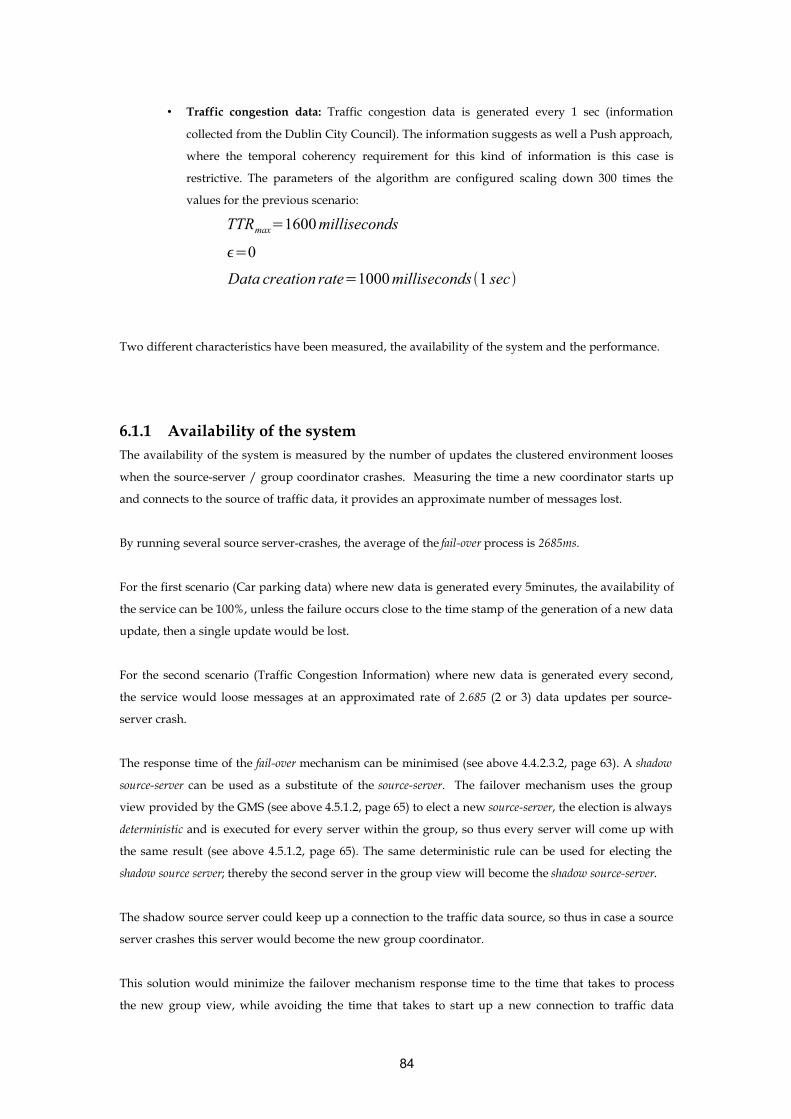
• Traffic congestion data: Traffic congestion data is generated every 1 sec (information
collected from the Dublin City Council). The information suggests as well a Push approach,
where the temporal coherency requirement for this kind of information is this case is
restrictive. The parameters of the algorithm are configured scaling down 300 times the
values for the previous scenario:
TTRmax=1600 milliseconds
=0
Data creation rate=1000 milliseconds 1 sec
Two different characteristics have been measured, the availability of the system and the performance.
6.1.1 Availability of the systemThe availability of the system is measured by the number of updates the clustered environment looses
when the source-server / group coordinator crashes. Measuring the time a new coordinator starts up
and connects to the source of traffic data, it provides an approximate number of messages lost.
By running several source server-crashes, the average of the fail-over process is 2685ms.
For the first scenario (Car parking data) where new data is generated every 5minutes, the availability of
the service can be 100%, unless the failure occurs close to the time stamp of the generation of a new data
update, then a single update would be lost.
For the second scenario (Traffic Congestion Information) where new data is generated every second,
the service would loose messages at an approximated rate of 2.685 (2 or 3) data updates per source-
server crash.
The response time of the fail-over mechanism can be minimised (see above 4.4.2.3.2, page 63). A shadow
source-server can be used as a substitute of the source-server. The failover mechanism uses the group
view provided by the GMS (see above 4.5.1.2, page 65) to elect a new source-server, the election is always
deterministic and is executed for every server within the group, so thus every server will come up with
the same result (see above 4.5.1.2, page 65). The same deterministic rule can be used for electing the
shadow source server; thereby the second server in the group view will become the shadow source-server.
The shadow source server could keep up a connection to the traffic data source, so thus in case a source
server crashes this server would become the new group coordinator.
This solution would minimize the failover mechanism response time to the time that takes to process
the new group view, while avoiding the time that takes to start up a new connection to traffic data
84

source. This strategy would introduce a new computational overhead at the proxy-server as it acts as
well as shadow source-server.
6.1.2 Performance The performance of the system has been measured by running a set of concurrent threads that will send
request messages to the system; several tests have been run scaling up the number of concurrent
running threads. For this particular test, the load balancing mechanism has been removed. This is
because the cluster is configured with two machines only, thus requests will be sent to the proxy-server
while the group coordinator will act only as source-server (group coordinators can act both source-server
and proxy-servers if they are configured in the load balancing mechanism).
Four set of tests have been run, (1) 100 Threads, (2) 200 Threads, (3) 500 Threads, (4) 1000 Threads.
Response time average
12
3 4
12
3 4
0
20
40
60
80
Test
Tim
e (m
s)
Parking DataCongestion Data
Parking Data 31.1 40.675 10.28 11.969
CongestionData
62.33 47.325 13.15 13.555
1 2 3 4
Figure 6.1 Response time average (milliseconds - ms)
Congestion Data has less performance than parking data, this is due to the frequency of the updates
that are pushed to the proxy servers, this updates require locking the data for writing at the proxy-
server’s replicated cache. This locking mechanism introduces a minimum computational overhead that
militate against performance.
The first test scenario, that runs 100 threads, has a significant difference compared with the other tests.
The reason of such difference is due to the fact that the test are executed after a clean start up of the
servers, this means that neither of the proxy servers has in the XSLT caches (see above 5.1.1.1, page 69)
the Transformer object for the XML transformations. As well as the fact that the Resin server has to
initialize in the Servlet Container the pool of Servlet objects (instances) associated with the same Servlet
class name. Each of the instances is ready (initialized) to be dispatched to a request thread by the
container.
85

The following graphics show the initial peak due to this initialization process.
The initial peak corresponds to the XSL Transformer object instantiation, then we the pool of Servlets is
created. The peaks scattered throughout the graph are due to the computational overheads while
updating cached objects.
Figure 6.2 Response time per thread request (milliseconds – ms)
Figure 6.3 Response time per thread request (milliseconds - ms)
These graphics demonstrate as well the performance benefits by usage of a XSLT cache at the
Presentation Tier.
.
Response times are acceptable, but the must be run in a deployment environment with dedicated
computers and a significant increment of data.
86
Congestion Information
0100200300400500600700
1 8 15 22 29 36 43 50 57 64 71 78 85 92 99
Request Identifier
Res
pons
e Ti
me
(ms)
Congestion Information
Car parking data
0100200300400500600700
1 8 15 22 29 36 43 50 57 64 71 78 85 92 99
Request Identifier
Res
pons
e Ti
me
(ms)
Car parking data

6.1.3 Communication ProtocolThe communication protocol used for replicating cached data is based on probabilistic multicast
(pbcast). The evaluation of this protocol [36] is framed in the context ability of the algorithm to scale;
pbcast scales as the number of processes increases, according to several metrics [36] :
• Reliability: The reliability of the protocol grows with the system size. As the number of
members grows, the protocol is more reliable.
• Message Cost: The cost per group member is measured by the number of messages sent or
received. This cost remains constant as the system grows.
6.1.4 Lazy Pull and Push AlgorithmThe purpose of the algorithm is to keep up-to-date information and use network resources in an
intelligent way minimizing the overhead of sending unnecessary messages across the network. For this
purpose a slightly modified version of the Push-and-Pull algorithm [32] was chosen and adapted to the
needs of ITS services. The algorithm achieves the following [35]:
• Adaptability: The algorithm must response quickly to changes in the system state and
adapts its operations to new evolving conditions.
• Generality: The algorithm should be general enough to serve a wide range of traffic data
types.
• Minimum Overhead: The algorithm should respond to requests quickly, incurring
minimal overhead on the system (processing, memory usage, network I/O).
• Flexibility: The algorithm should be tuneable from a push to a pull strategy, as it can be
needed to adapt its behaviour at run time.
It is difficult to determine whether a push or a pull strategy should be employed for a particular traffic
data type. The technique used, Lazy Pull and Push, adaptively determines which strategy is best suited
for a particular instant. Tuning the behaviour of the algorithm, from a pull approach to a push
approach, must be done based on the following:
• The end-user temporal coherency requirement.
• Characteristics of the traffic data.
87

The tuning is has to be done taking in consideration [32] the values of and TTRmax , that will enable
the system to perform from a Push to a Pull approach. Larger values of TTRmax will make the system
acts as Push, while on the contrary smaller values will make the system acts as Pull.
There are some scenarios described in [32] that will help the choice of the best strategy for the system.
From the performance study done in [32] some conclusions can be extrapolated, which they will help to
address the values to use for tuning the algorithm for Traffic Data.
6.1.4.1 Tuning the algorithm for Traffic DataParking traffic data do not have strict time constraints, and they are changing at slow rate. A Pull-based
approach will make the proxy-servers poll more frequently than necessary. Hence a Pull-based
approach is liable to impose a larger load on the network, as this requires two messages, a request and
a response.
Then a Push-based approach is desirable for parking data. As the data changes at slow rate, and the tcr
is not required to be very low; the source server will not incur much network overhead sending
frequent updates.
On the other hand, although a Push strategy has a computational overhead proportional to the rate at
new data is generated, this is not the case for parking data, as is has been said before, this data changes
only slowly.
If the traffic data to be disseminated do not requires a low tcr, and data is generated at a high rate. A
Push-based strategy that will incur overheads sending unnecessary updates is not necessary. A Pull-
based approach can be configured by setting TTRmax to a low/moderate value (it will increase pulls)
and/or to a moderate/high value (it will decrease pushes).
For traffic data that changes at a high rate and the tcr is low, a Push-based approach is more appropriate
as the network overhead is less than a Pull-based approach.
The tuning of the algorithm is not trivial, there are some scenarios that will help us configure the
different parameters (see above 5.3.1.4, page 78). Some of the typical scenarios are [32]:
“If the bandwidth available is low and yet, high fidelity is desired, then we choose a moderate TTRmax
and low.
88

If the bandwidth available is low, and fidelity desired is also not high, then we can set TTRmax and both to a moderate value.
If the bandwidth available is high and fidelity desired is also high, then we can set TTRmax low and
equal to TTRmin , thus having less pushes (and more pulls) but still good fidelity.
If the bandwidth available is high and fidelity desired is not stringent, then a lower value can be set for
TTRmax , thereby making the system resort to pulls”.
6.2 Technology Evaluation
6.2.1 JGroupsJGroups usage has provided potential benefits (see above 3.4.2, page 35) for the architecture
implementation. These benefits and the short time for the implementation would not have been
achieved without the use of JGroups. However JGroups has a series of drawbacks.
6.2.1.1 JGroups drawbacks
6.2.1.1.1 GMS Group Management Service The basic set of JGroups micro protocols, included with the JChannel implementation, provides [34]
some very strong guarantees in terms of quality of service for the protocol stack. The group
management service GMS, is based on the virtual synchrony model [36]. Each member installs a
sequence of views (membership lists) through time and is guaranteed to receive the same set of
messages between views. Any message sent in one view is also guaranteed to be received in that view.
While this is stable for small memberships, the implementation is not stable for a very large
membership. In fact, the virtual synchrony implementation in JGroups can be quite problematic with
large group memberships.
In order to support very large memberships JGroups provides a set of multicast protocols based on
probabilistic broadcast. Probabilistic multicast protocols are scalable in two senses:
• Reliability
[36]The reliability of the protocol is expressed in terms of the probability to fail. This
probability approaches to 0 at an exponential rate as the number of processes increase. This
89

is achieved by usage of a gossip protocol; these protocols typically flood the network
within a logarithmic number of rounds.
• Message Cost
[36]The latency of the protocol and the message cost at slow rate with the system size.
6.2.1.1.2 State Transfer ProtocolA deep-copy (a member-by-member copy of every referenced object) of the state has to be made
because it is possible that the STATE_TRANSFER [43] protocol may hold on to the state for a while,
before it is transmitted over the wire. If any object referenced by the state is modified at this time, the
state transmitted can become inconsistent. In fact, because a deep copy of the state can take too much
time, the state must be protected from concurrent access during the copy through synchronization of
state operations, in other words, by a locking mechanism.
6.2.1.1.3 JGroups building blocksTwo building blocks have been used for the actual implementation, DistributedTree [42] and
DistributedHashtable [42]. These high-level abstractions are usually placed between the communication
channel and the application. But they have a communication overhead for a particular scenario. A
proxy-server acts as well as a source-server when the cluster has only one member. For such case there
is no needed to send messages to the multicast group when an operation (add, remove, update) is
performed on the data structures they manage, but this is not controlled by these two building blocks.
Since JGroups is an open source project, the require modifications, that fixed this overhead, were made
and submitted to the JGroups project. This involved the modification of several building blocks
(DistributedTree, DistributedHashtable, ReplicatedTree, and ReplicatedHashtable [42]). It has been added the
logic required to control when messages have to be multicast to the group or not, the solution uses the
GMS protocol. As these building blocks receive group view changes, when a new group view is
received, the number of members of the group is computed. When the number of members is bigger
than one, the messages will be multicast to the group; but when the number of members is only one
there is no need to send messages across the network.
This change in the code increases the performance by reducing the response time of the application, as
the changes in the elements stored in these containers are performed when the message is received by
all the members of the group. The architecture economises on bandwidth resources due to a more
efficient use of the multicast channel.
90

6.2.2 The use of AspectsThe use of Aspects has been crucial for the actual implementation of the architecture. Aspects have been
applied for the following purposes:
The implementation of several Factories [26] and Abstract Factories [26], of which the most significant
has been the Abstract Factory [26], for the Command pattern [26] used for sending commands from the
presentation tier to the business tier.
• Code extension using inter-type declarations.
• Concurrency Control.
• The implementation of the two algorithms used for updating data in the two caches used.
• The implementation of a monitoring tool for purposes of the demo.
With the use of AOP the architecture has gained in the following aspects:
• Flexibility: Aspects allow adding functionality in a non-pervasive way, enabling the
architecture to evolve with a minimum impact over the code. As we can add the aspects in
a pluggable way.
• Modularity: Aspects has enabled the design of modularized component in a way that we
have avoided the drawbacks of code scattering and code tangling derived from of the use
of a rigid object oriented approach.
• Maintainability: The code is much easier to maintain as the crosscutting concerns are
localized in one place instead of being dispersed through our code.
It is important to comment that AOP has been crucial for the implementation of the Lazy Pull and Push
algorithm (see above 5.3.1.4, page 78). The algorithm has bee designed as a combination of two
modularized and decoupled components. This will give us the flexibility required to re-use the
algorithm for other traffic data rather than Parking data. The only thing to perform is a minimal tuning
of the parameters used by the algorithm in order to perform the most efficient way.
6.2.2.1 AspectJAspectJ provides a set of constructs to use in order to define crosscutting concerns. These constructs
have a clear syntax. The Joinpoints allow us to define pointcuts in the execution of the application. By
implementing Advices we are able to perform additional functionality when the joinpoint is reached.
The definition of these constructs in an Aspect can do the developer’s job harder when the aspect class
definition increases in size, by the addition of more Joinpoints and their associated advices.
The AspectJ compiler uses a pay-as-you-go implementation strategy. Any parts of the program that are
unaffected by advice are compiled just as they would be by a standard Java compiler. The compiler has
three main limitations:
91

• It uses javac as a back-end rather than generating class files directly.
• It requires access to all the source code for the system.
• It performs a full recompilation whenever any part of the user program changes.
The AspectJ compiler supplies a small (< 100K) runtime library that performs a minimum compilation
overhead. AspectJ team works on building incremental compiler. Fast incremental compilation for
AspectJ is an area for future research.
The generated compiled code does not introduce any performance overhead [51]. At present there is no
benchmark suite for AOP languages no for AspectJ in particular. The language has to mature.
“Coding styles really drive the development of the benchmark suites since they suggest what
is important to measure. In the absence of a benchmark suite, AspectJ probably has an
acceptable performance for everything except non-static advice. Introductions and static
advice should have extremely small performance overheads compared to the same
functionality implemented by hand”.
“The ajc compiler will use static typing information to only insert those checks that are
absolutely necessary. Unless you use 'thisJoinPoint' or 'if', then the only dynamic checks
that will be inserted by ajc will be 'instanceof' checks which are generally quite fast. These
checks will only be inserted when they can not be inferred from the static type information”.
The way to measure the performance the code with code fragments in AspectJ has to be compared with
the corresponding code written without AspectJ.
92

Chapter 7
Conclusions
This chapter summarizes the work that has been carried out and the goals and objectives achieved
during the duration of this challenging project. It also refers some architectural and design
considerations and decisions, that have been taken during this dissertation. These decisions have
influenced drastically the final result. Different types of users can benefit from the use of this project.
The knowledge obtained during this dissertation, will help the many possibilities described for
improving the proposed architecture as future work.
7.1 AchievementsAs a result of the research carried out during this project, a multi-tiered architecture has been designed
implemented and evaluated. This architecture satisfies the main objectives and requirements specified
and the start of the project. Finally, some of the different possibilities for future work, that could be
performed upon the knowledge obtained and the work done, are summarized.
The achievements are described under the scope of an ITS, this will provide further understanding of
the work done and it will provide a helpful reference for future work.
7.1.1 Multimodality The architecture designed and developed provides neutral and device independent information
dissemination. This independence has been achieved by the definition of a data model based on an
XML standard (see above 3.2.1.1, page 22). Since the architecture delivers plain XML; this provides ease
extension and evolution of the actual implementation of the Presentation tier. New presentation view
components can be added easily in order to serve a new device with minimum code maintenance, since
the view logic management is performed by a reusable component (see above 5.1.1, page 68).
Developing new XSL components for each required view we can transform he presentation to any
presentation we require, under the consideration of the technological limitations of the XSL standard.
7.1.2 ScalabilityScalability is one of the most successful goals. The implemented architecture provides different kinds of
scalability at different levels (tier).
93

7.1.2.1 Multimodal PresentationThe presentation tier has the ability to transform the system output to any kind of device presentation
7.1.2.2 Scalability at the Presentation TierThe presentation or web tier has the ability to scale by increasing the number of web-servers to handle
increased load. The deployment of new servers can be easily done by setting them up in the resin config
file (see above 4.4.1.1, page 54)
7.1.2.3 Scalability at the Proxy TierThe proxy tier represents the core of the cached traffic data dissemination. By adding new proxy-servers
to the cluster, we can handle an increase of load at the web/presentation tier (increment of end-user's
requests).
Parking information does not represent a bottleneck at the source-server, but it can be possible that
providing another kind of traffic information can represent a computational overload due to the
amount of data to be handled. The architecture handles this overload by scaling up the number of
multicast groups. Different alternatives can be considered (see below 7.3, page 97)
Figure 7.1 Scalability at the Proxy Tier I
94

Figure 7.2 Scalability at the Proxy Tier II
Scalability of the Data
The proposed XML schema (see above 4.6.1, page 67) has been devised for traffic parking data. By
using schema definitions it can be composed a higher level of abstraction, with a hierarchical
composition of traffic data schema definitions. This flexibility provided by the efficient use of schemas,
gives the actual architecture the potential ability of scaling up the different data types to handle (see
below 7.3, page 97).
7.1.3 Fault Tolerant Another benefit provided is that the overall system does not have to recover from a server failure,
because of to two reasons: (i) the failover mechanism implemented provides a new server that will
connect to the data source and will continue delivering data (see above 4.4.2.3.2, page 63), and (ii) the
lightweight state kept in the server does not requires a failure recovery mechanism to copy its previous
state (see above 5.3.1.4, page 78).
95

7.1.4 Flexible caching algorithmThe algorithm implemented can be tuned based on some system conditions. So thus, changing some
tuneable parameters we can achieve Push or Pull strategies or a hybrid approach. This provides the
architecture width great flexibility. Depending on the traffic data to be stored in the cache, and the
specified user's temporal coherency requirement, the cache can behave in a way that satisfies our needs
or requirements.
Proxy-servers are responsible for pulling for changes when the data is required by the user, as the
strategy used is lazy in a way that only when the user requests a particular data, the calculated TTR, is
validated. This lazy approach can be easily changed to an active one. Parking traffic data do not have a
strong time constraint, but of course, other traffic data type (congestion, emergency) can require an
active pull strategy, where the proxy server actively checks for time expirations of the cached data and
pulls the server for updates.
7.1.5 ExtensibilityThe architecture devised is layered in several tiers (see above 4.2, page 42); each one has a concrete role
within the whole system that scopes its responsibilities. These responsibilities have been addressed by
the development of several aspects, and components. Tiers are decoupled due to the design patterns
used for the implementation (see above 5, page 68) and they provide well defined interfaces that allow
add new functionality easily. For example it can be added a Congestion Service or an Emergency
Service for disseminating congestion information and emergency information respectively. The core of
both services would be allocated at the Business Tier (see above 4.2.2, page 44); the Presentation Tier (see
above 4.2.1, page 43) would only have to add new Command [26], these commands decouple the
business logic form the presentation logic exposing a common interface that every new command has to
implement. The Proxy Tier (see above 4.2.3,page 44) can handle the traffic data associated with both
services transparently. The data stored in the cache is defined by an interface (java.io.Serializable).
Since the new services should follow the standard defined in the architecture, the new traffic data to
handle will be defined by a Schema definition (see above 4.6.1,page 67) . This Schema will be compiled
into one or more Java classes (see above 3.2.2.4.1, page 26). These classes will be re-factored the same
way it has been done for parking data in order to (i) apply the algorithm to the car parking data
objects, (ii) send these objects across the network. The Connector Tier (see above 4.2.4,page 45) would
contain new connectors that will provide both congestion and emergency traffic data respectively.
Following this process, new traffic related end-user services can be added to the system (e.g. a
Congestion Service to disseminate congestion information).
96

7.2 Potential users and Applications
The resulting architecture will enable the development of future ITS end-user services. Dublin City
Council in collaboration with the iTranIT; iTranIT is a project under the Distributed Systems Group in
Trinity College Dublin. iTranIT investigates in cooperation wit Dublin City Council an ITS architecture
for Dublin City [52]
Future applications to be considered can be:
• Journey planner
• Real-time and pre-trip information through the internet
• Public transport information over the internet
• Public transport planner
• Real-time Bus information
• Parking guidance
• Tourism information
• Weather information
• Airline schedule information
• Measured congestion information integration with the actual running system, and
prediction congestion information
• Real-time on incidents, accidents, road construction, alternate routes, traffic regulations
and tolls.
7.3 Future workDue to the heterogeneity of the system, this project offers countless possible ways of research and future
work. The most relevant are described and summarized in order to provide useful and helpful
information for future researchers based on the knowledge obtained during the realization of this
challenging project.
7.3.1 Quality Of Service (QoS)Future end-users of traffic services, might determine the value of the tcr for a data type. This means that
the user might say the latest time he expects to receive congestion data in his mobile phone (e.g. if the
system cannot meet the tcr then the age of the data should be transmitted with it: 546 spaces free, 7
minutes old, valid at 17.34 on 9-Sep-03). So tcr would help us to manage custom care policies for end-
users, providing a range of Quality of Service (QoS) classes.
97

The actual service might evolve in a way that could allow end-users a higher interaction with the
system. Users might demand spaces at car parking places at a date time and the system could make
estimations of future car occupations. This valuable information might be used for end-users to decide
which car parking to go, based on the actual car occupation status and the prediction of the system.
Traffic Data Services can be devised in order to enable future users configure and personalize these
services to their needs, providing a customer care service. ITS can benefit of these end-user information
to provide high quality traffic related services (e.g. Car parking and Public Transportation demand,
Public transport planner).
7.3.2 Multimodal InteractionMulti channel delivery technology simply adapts contents. The usability of the same document on
"poor" channels is very different from the usability on "rich" channels like the web. It could probably be
better if the user could use the different channels in the same moment to visit the same service.
Multimodal interfaces are interfaces where the interaction between the service and the user is kept on
using different channel simultaneously. For example a user can choose to complete a form speaking,
but can navigate to the next page using the pen given with its PDA. Future work could explore the
possible multimodal strategies for enabling the use of different channels simultaneously.
7.3.3 Extending the Traffic Data Schema DefinitionA possible future work is to carry out a further study of the traffic data in order to design a whole traffic
data model. The actual schema was designed for parking data, but can evolve easily in order to address
a future traffic data model. It is important to realize that changes in the actual schema will incur
changes in the actual implementation. Then we will have to generate the Java classes for the updated
schema again.
7.3.4 Collaborative CachesBased on the actual implementation and on the previous section, the architecture could evolve to a set
of collaborative caches that would collaborate with one another by pushing data of interest to improve
the efficiency of dissemination and maintaining the user's tcr [33].
98

Figure 7.3 Collaborative Caches
Evolution to a Distributed Architecture of Specialized Clusters
A feasible evolution of the actual architecture is to create different cluster of servers, each one will be
dedicated to retrieve and disseminate a particular traffic data type or several ones. This strategy would
scale to the number of groups we need, and each cluster would be composed by a countless number of
proxy servers. The final outcome would be the creation of a kind of distributed computational system.
The creation of specialized clusters can be easily achieved by a simple modification of the JGroups
protocol stack configuration file. It only has to change the name of the multicast group. All the proxy
servers that are members of the same group will have to use the same configuration file.
We would place the end-user services and applications on top of this distributed system; a redirection
mechanism should be implemented to redirect the requests to the specialized group that manages the
type of the service required. Services might be devised by the composition of others. For every group or
cluster, we would use a load balancing mechanism that would handle and balance the group load
among the different proxy-servers.
99

Figure 7-7.4 Distributed System - Specialized Clusters
The algorithm used (see above 4.3.2, page46) to refresh data in the replicated caches can be tuned then
to accommodate the tcr and based on the data type to refresh and the rate of creation.
A step beyond, towards Grid Computing Architecture
A clear further evolution would come up by the junction of the two previously pointed areas of
research, (i) Specialised Clusters and (ii) Collaborative Caches. The architecture could evolve to a grid
computing system where multiple ITS services might be deployed, providing a virtual system of
distributed computing and data under a single system image. This grid architecture would enable
communication across heterogeneous, geographically dispersed environments. The possibilities of such
system would provide are countless, ITS services would interact and cooperate providing a flexible
mixture of end-user services. ITS services would be added in the system a pluggable fashion.
Weather information services and Emergency information services (information on incidents, accidents,
road construction, and alternative routes) would collaborate with Real-time and pre-trip information
providing weather data. Journey Planners services would cooperate with Congestion Information
Services providing useful end-user’s information for congestion prediction. Airline schedule
information services, Journey Planners and Congestion Information Services would collaborate
providing complete information for end users’ trip planning. All these services would be viewed as
collaborative peers within a ubiquitous single system image, such system would conform an ITS.
100

Appendix
Parking Web Application Load Balancing
front.conf
<http-server>
<http port='80'/>
<srun id='back1' srun-group='a' srun-index='1' host='192.168.0.1' port='6802'/>
<srun id='back2' srun-group='a' srun-index='2' host='192.168.0.2' port='6802'/>
<servlet>
<servlet-name>balance-a</servlet-name>
<servlet-class>com.caucho.http.servlet.LoadBalanceServlet</servlet-class>
<init-param srun-group='a'/>
</servlet>
<servlet-mapping url-pattern='/parking/*' servlet-name='balance-a'/>
</http-server>
back.conf
<http-server>
<srun id='a' host='192.168.0.1' port='6802' srun-index='1'/>
<session-config>
<tcp-store>
</session-config>
</http-server>
web.xml
<?xml version="1.0" encoding="UTF-8"?>
<!DOCTYPE web-app PUBLIC "-//Sun Microsystems, Inc.//DTD Web Application 2.3//EN"
"http://java.sun.com/dtd/web-app_2_3.dtd">
<!-- ITS - KAREN - Parking WebApp Deployment Descriptor-->
<!-- This file contains the definitions needed in order to deploy the Parking WebApp on any J2EE-
compliant application server-->
<web-app>
<!-- NOTE: Wheter a url pattern is described, bear in mind that has to be relative to
http://host:port/mywebapp/-->
101

<description/>
<!-- #################################### -->
<!-- Define the filters within the WebApp -->
<!-- #################################### -->
<!-- XSL Transformation Filter-->
<filter>
<filter-name>XSLT_Filter</filter-name>
<description>
This filter applies XSL transformation to the XML output sent by the Servlet to the user
</description>
<filter-class>
com.its.karen.userservices.parking.presentation.interceptorfilters.xslt.XSLTransformationFilter
</filter-class>
<init-param>
<param-name>xsltFile</param-name>
<param-value>/WEB-INF/Parking.xslt</param-value>
</init-param>
<init-param>
<param-name>cacheType</param-name>
<param-value>DISTRIBUTED</param-value>
</init-param>
</filter>
<!-- [END ] XSL Transformation Filter -->
<!-- ######################################## -->
<!-- Map the filters to a Servlet or to a URL-->
<!-- ######################################## -->
<!-- XSL Transformation Filter-->
<filter-mapping>
<filter-name>XSLT_Filter</filter-name>
<url-pattern>/parking</url-pattern>
</filter-mapping>
<!-- [END] XSL Transformation Filter -->
<!-- ############################################## -->
<!-- Define the Servlets within the Web Application -->
<!-- ############################################## -->
<servlet>
<servlet-name>FrontController</servlet-name>
<description/>
<servlet-class>
com.its.karen.userservices.parking.presentation.frontcontroller.FrontControllerServlet
</servlet-class>
</servlet>
102

<servlet>
<servlet-name>TransferDataManagerController</servlet-name>
<description/>
<servlet-class>
com.its.karen.userservices.parking.presentation.frontcontroller.TransferDataServlet
</servlet-class>
</servlet>
<!-- ############################### -->
<!-- Define Servlet mappings to URLS -->
<!-- ############################### -->
<servlet-mapping>
<servlet-name>FrontController</servlet-name>
<url-pattern>/Parking</url-pattern>
</servlet-mapping>
<servlet-mapping>
<servlet-name>TransferDataManagerController</servlet-name>
<url-pattern>/transferDataManager</url-pattern>
</servlet-mapping>
</web-app>
JGroups
JGroups Protocol Stack XML Configuration
<!-- $Id: DistributedParkingData.xml,v 1.2 2003/08/07 13:37:32 oliassaa Exp $ -->
<protocol-stack name="Protocol stack to be used for testing
transferring of state" version="1.0.0">
<description>javagroups State Transfer Protocol Stack</description>
<protocol>
<protocol-name>UDP Protocol</protocol-name>
<description>Sends and receives messages on UDP sockets</description>
<class-name>org.javagroups.protocols.UDP</class-name>
<protocol-params>
<protocol-param name="mcast_addr" value="228.8.8.8"/>
<protocol-param name="mcast_port" value="45566"/>
<protocol-param name="ucast_send_buf_size" value="16000"/>
<protocol-param name="ucast_recv_buf_size" value="16000"/>
<protocol-param name="mcast_send_buf_size" value="32000"/>
<protocol-param name="mcast_recv_buf_size" value="64000"/>
103

<protocol-param name="loopback" value="true"/>
<protocol-param name="ip_ttl" value="32"/>
</protocol-params>
</protocol>
<protocol>
<protocol-name>Auto Configuration</protocol-name>
<description>Senses the network properties and
allows other protocols to configure themselves
automatically</description>
<class-name>org.javagroups.protocols.AUTOCONF</class-name>
<protocol-params>
</protocol-params>
</protocol>
<protocol>
<protocol-name>Ping Protocol</protocol-name>
<description>Find the initial membership</description>
<class-name>org.javagroups.protocols.PING</class-name>
<protocol-params>
<protocol-param name="timeout" value="2000"/>
<protocol-param name="num_initial_members" value="3"/>
</protocol-params>
</protocol>
<protocol>
<protocol-name>Merge Protocol</protocol-name>
<description>Periodically tries to detect subgroups and emits MERGE events in
that case</description>
<class-name>org.javagroups.protocols.MERGE2</class-name>
<protocol-params>
<protocol-param name="min_interval" value="5000"/>
<protocol-param name="max_interval" value="10000"/>
</protocol-params>
</protocol>
<protocol>
<protocol-name>Failure Detection Socket</protocol-name>
<description>Failure detection based on sockets</description>
<class-name>org.javagroups.protocols.FD_SOCK</class-name>
</protocol>
<protocol>
<protocol-name>Verify Suspect</protocol-name>
<description>Double-checks that a suspected member is really dead</description>
<class-name>org.javagroups.protocols.VERIFY_SUSPECT</class-name>
<protocol-params>
104

<protocol-param name="timeout" value="1500"/>
</protocol-params>
</protocol>
<protocol>
<protocol-name>Reliable mcast message transission</protocol-name>
<description>Uses a negative acknowledgement protocol for
retransmissions</description>
<class-name>org.javagroups.protocols.pbcast.NAKACK</class-name>
<protocol-params>
<protocol-param name="gc_lag" value="50"/>
<protocol-param name="retransmit_timeout"
value="300,600,1200,2400,4800"/>
<protocol-param name="max_xmit_size" value="8192"/>
</protocol-params>
</protocol>
<protocol>
<protocol-name>Unicast Protocol</protocol-name>
<description>Provides lossless transmission of unicast message (similar to TCP)
</description>
<class-name>org.javagroups.protocols.UNICAST</class-name>
<protocol-params>
<protocol-param name="timeout" value="2000"/>
</protocol-params>
</protocol>
<protocol>
<protocol-name>Stable protocol</protocol-name>
<description>Distributed message garbage collection protocol. Deletes messages
seen by all group members</description>
<class-name>org.javagroups.protocols.pbcast.STABLE</class-name>
<protocol-params>
<!-- Periodically sends STABLE messages around. 0 disables this -->
<protocol-param name="desired_avg_gossip" value="20000"/>
<!--
Max number of bytes received from anyone until a STABLE message is sent. Use either this or
desired_avg_gossip, but not both ! 0 disables it.
-->
<protocol-param name="max_bytes" value="0"/>
<!--
Range (number of milliseconds) that we wait until sending a STABILITY message. This
prevents
STABILITY multicast storms. If max_bytes is used, this should be set to a low value (> 0
though !).
105

-->
<protocol-param name="stability_delay" value="1000"/>
</protocol-params>
</protocol>
<protocol>
<protocol-name>Fragmentation Protocol</protocol-name>
<description>Divides up larger message into smaller pieces</description>
<class-name>org.javagroups.protocols.FRAG</class-name>
<protocol-params>
<protocol-param name="frag_size" value="8192"/>
<protocol-param name="down_thread" value="false"/>
<protocol-param name="up_thread" value="false"/>
</protocol-params>
</protocol>
<protocol>
<protocol-name>PB Cast Group Membership Protocol</protocol-name>
<description>Maintains the member ship view</description>
<class-name>org.javagroups.protocols.pbcast.GMS</class-name>
<protocol-params>
<protocol-param name="join_timeout" value="5000"/>
<protocol-param name="join_retry_timeout" value="2000"/>
<protocol-param name="shun" value="false"/>
<protocol-param name="print_local_addr" value="true"/>
</protocol-params>
</protocol>
<protocol>
<protocol-name>State transfer</protocol-name>
<description>Transfers the state to a joining member</description>
<class-name>org.javagroups.protocols.pbcast.STATE_TRANSFER</class-name>
</protocol>
</protocol-stack>
106

Bibliography1: ITS Europe (ERTICO), http://www.ertico.com/
2: ITS Japan, www.iijnet.or.jp/vertis/
3: ITS America, www.itsa.org
4: ITS Australia, , http://www.its-australia.com.au/
5: L. Nigay and J. Coutaz., A design space for multimodal systems - concurrent processing and data fu-sion, 1993
6: Scott W. Ambler, Advanced XML? No, Just Realistic XML. Bringing data professionals and applica-tion developers together, 2003
7: XSL Transformations (XSLT) Version 1.0, Sun Microsystems http://java.sun.com/xml
8: W3C, W3C Schema, http://www.w3.org/XML/Schema
9: W3C, XSL Transformations (XSLT), http://www.w3.org/TR/xslt
10: W3C, Extensible Markup Language (XML) Standards, http://www.w3.org/XML/
11: W3C, Document Object Model (DOM), http://www.w3.org/DOM/
12: SAX, Simple API for XML, http://www.saxproject.org/
13: Sun Microsystems, Java Architecture for XML Binding (JAXB), http://java.sun.com/xml/jaxb/
14: Sun Microsystems, JAXP documentation, http://java.sun.com/xml/jaxp/index.html
15: WAP / WML Tutorial, http://www.w3schools.com/wap/default.asp
16: W3C, HTML/XHTML , http://www.w3.org/MarkUp
17:VoiceXML, http://www.voicexml.org,
18: SALT, http://www.saltforum.org/,
19: Stephanie Bodoff and Dale Green and Kim Haase and Eric Jendrock and Monica Pawlan and BethStearns, The J2EE Tutorial, , Sun Microsystems http://java.sun.com/j2ee/tutorial/1\_3-fcs/index.html
20: Sun Microsystems, The Essentials of Filters, http://java.sun.com/products/servlet/Filters.html
21: Filter code with Servlet 2.3 model, http://www.javaworld.com/javaworld/jw-06-2001/jw-0622-fil-ters.html
22: D. Brookshier, D. Govoni, N. Krishnan, JXTA: Java P2P Programming, SAMS
23: Niklas Påhlsson, An Introduction to Aspect-Oriented Programming and AspectJ
24: http://dictionary.reference.com,
107

25: KAREN, EUROPEAN ITS ARCHITECTURE, http://www.frame-online.net/eitsfa.htm
26: E. Gamma and R. Helm and R. Johnson and J.Vlissides, Design Patterns: Elements of ReusableObject-Oriented Software, Addison Wesley, 2000
27: C. Olston and J. Widom, Best-Effort Cache Synchronization with Source Cooperation, {SIGMOD}Conference, 2002
28: S.Brin and L.Page, The anatomy of a large-scale hypertextual {Web} search engine, ComputerNetworks and ISDN Systems, 1998
29: G. Barish and K. Obraczka, World Wide Web Caching: Trends and Techniques, IEEE Communi-cations Magazine Internet Technology Series,2000
30: P. Cao and C. Liu, Maintaining Strong Cache Consistency in the World Wide Web, IEEE Transac-tions on Computers, 1998
31: Dan Li and David R. Cheriton, Scalable Web Caching of Frequently Updated Objects Using Reli-able Multicast, 1999
32: P. Deolasee and A. Katkar and A. Panchbudhe and K. Ramamritham and P.J. Shenoy, Adaptivepush-pull: disseminating dynamic web data, World Wide Web
33: P.Cao and C. Liu, Maintaining Statistics Counters in Router Line Cards, IEEE Transactions onComputers,1998
34: Sing Li, High-impact Web tier clustering: Scaling Web services and applications with, 2003,www-106.ibm.com/developerworks/java/library/j-cluster1
35: Buyya Rajkumar , High Performance Cluster Computing, 1999
36: Kenneth P. Birman, BuildingSecure and ReliableNetwork Applications, Manning PublicationsCo.,1996
37: G.Coulouris and J.Dollimore and T.Kindberg, Distributed Systems Concepts and Design (3rdEdition), Addison-Wesley,2001
38: Mark Hayden and Kenneth Birman, Probabilistic Broadcast, Cornell University Technical Re-port, 1996
39: Y. Azar and M.Feder and E.Lubetzky and D.Rajwan and N. Shulman, The Multicast BandwidthAdvantage in Serving Web Site.
40: D. Dolev and O. Mokryn and Y. Shavitt and I. Sukhov, An integrated architecture for the scalabledelivery of semi-dynamic web content, Hebrew University, Tech. report 2001.
41: B Ban, JGroups User Guide 1.0, http://www.javagroups.com/javagroupsnew/docs/ug.html
42: B Ban, JGroupsUserGuide2_0, http://www.javagroups.com/javagroupsnew/docs/ug.html
43: B. Ban, A Flexible API for State Transfer in the JavaGroups Toolkit
44: Sun Microsystems, JAXP documentation, http://java.sun.com/xml/jaxp/index.html
45: A Valikov, Transparently cache XSL transformations with JAXP,
46: D.Lea, Concurrent Programming in Java(TM): Design Principles and Pattern (2nd Edition), Addi-son Wesley Pub Co,1999.
47: D.Lea, Concurrent Programming in Java tm Design principles and patterns, supplement to thebook Concurrent Programming in Java: Design Principles and Patterns by Doug Lea, http://gee.cs.os-wego.edu/dl/cpj/
108

48: D.Alur and J.Crupi and D.Malks, J2EEPatterns, Prentice Hall,2001
49: J.W Cooper, Design Patterns Java Companion, Addison Wesley,1998
50: Martin Fowler, Refactoring, Proceedings of the 24th International Conference on Software En-gineering ({ICSE}-02)
51: AspectJ Frequently Asked Questions, http://dev.eclipse.org/viewcvs/indextech.cgi/~checkout~/as-pectj-home/doc/faq.html
52: iTranIT, http://www.dsg.cs.tcd.ie/?category_id=-40,
109