a - fluid mechanics foundations
TRANSCRIPT
A - FLUID MECHANICS FOUNDATIONS
Logo-DK
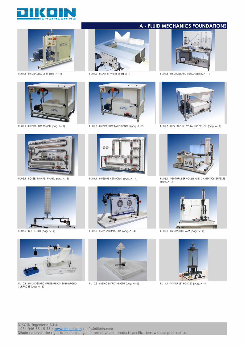
FL 01.1 - HYDRAULIC UNIT (pag. A - 1) FL 01.2 - FLOW BY WEIRS (pag. A - 1) FL 01.3 - HYDROSTATIC BENCH (pag. A - 1)
FL 01.4 - HYDRAULIC BENCH (pag. A - 2) FL 01.6 - HYDRAULIC BASIC BENCH (pag. A - 2) FL 01.7 - HIGH FLOW HYDRAULIC BENCH (pag. A - 2)
FL 02.1 - LOSSES IN PIPES PANEL (pag. A - 3) FL 04.1 - PIPELINE NETWORKS (pag. A - 3) FL 06.1 - VENTURI, BERNOULLI AND CAVITATION EFFECTS
(pag. A - 3)
FL 06.2 - BERNOULLI (pag. A - 4) FL 06.3 - CAVITATION STUDY (pag. A - 4) FL 09.2 - HYDRAULIC RAM (pag. A - 4)
FL 10.1 - HYDROSTATIC PRESSURE ON SUBMERGED
SURFACES (pag. A - 5)
FL 10.2 - METACENTRIC HEIGHT (pag. A - 5) FL 11.1 - WATER JET FORCES (pag. A - 5)
Catalogos-Pie19DIKOIN Ingeniería S.L.U.+034 946 55 15 35 / www.dikoin.com / [email protected] reserves the right to make changes in technical and product specifications without prior notice.

A - FLUID MECHANICS FOUNDATIONS
Logo-DK
FL 12.1 - FLOW THROUGH ORIFICES (pag. A - 6) FL 12.2 - HORIZONTAL FREE JET FLOW FROM A TANK
(pag. A - 6)
FL 13.1 - MANOMETER CALIBRATION (pag. A - 6)
FL 14.1 - VISCOSITY AND RESISTANCE COEFFICIENT
DETERMINATION (pag. A - 7)
FL 14.2 - REYNOLDS NUMBER (pag. A - 7) FL 14.3 - BALL DROP VISCOSITY TEST (pag. A - 7)
FL 15.1 - FORCED VORTEX (pag. A - 8) FL 15.2 - FORCED AND FREE VORTEX (pag. A - 8) FL 16.1 - FLOW VISUALISATION (pag. A - 8)
FL 16.2 - STREAMLINES VISUALIZATION IN A CHANNEL
(pag. A - 9)
FL 17.1 - PIPE FRICTION (pag. A - 9) FL 17.2 - LOSSES IN PIPES (pag. A - 9)
FL 18.1 - SECONDARY ENERGY LOSSES (pag. A - 10) FL 18.2 - LOSSES IN ELBOWS (pag. A - 10) FL 23.1 - FLOW METER STUDY (pag. A - 10)
Catalogos-Pie19DIKOIN Ingeniería S.L.U.+034 946 55 15 35 / www.dikoin.com / [email protected] reserves the right to make changes in technical and product specifications without prior notice.

A - FLUID MECHANICS FOUNDATIONS
Logo-DK
FL 28.1 - PASCAL APPARATUS (pag. A - 11) FL 29.1 - FLUID STATICS AND MANOMETRY (pag. A - 11) FL 29.3 - MANOMETER STUDY AND COMPARATION (pag.
A - 11)
FL 30.1 - FLUID PROPERTIES (pag. A - 12) FLB 03.1 - SERIES AND PARALLEL PUMP MODULE (pag.
A - 12)
FLB 03.2 - PUMP CHARACTERISTICS MODULE (pag. A -
12)
FLB 06.2 - BERNOULLI`s THEOREM (pag. A - 13) FLB 09.2 - HYDRAULIC RAM STUDY (pag. A - 13) FLB 10.1 - HYDROSTATIC PRESSURE (pag. A - 13)
FLB 11.1 - JET STREAM FORCES (pag. A - 14) FLB 13.1 - DEAD WEIGHT CALIBRATOR (pag. A - 14) FLB 14.2 - OSBORNE REYNOLDS DEMONSTRATOR (pag.
A - 14)
FLB 23.1 - FLOW METER DEMONSTRATION (pag. A - 15) FLQ-500-200lm - ELECTRONIC FLOW METER FOR
HYDRAULIC BENCH (pag. A - 15)
FLQ-500-30lm - ELECTRONIC FLOW METER 30l/min FOR
HYDRAULIC BENCH (pag. A - 15)
Catalogos-Pie19DIKOIN Ingeniería S.L.U.+034 946 55 15 35 / www.dikoin.com / [email protected] reserves the right to make changes in technical and product specifications without prior notice.

A - FLUID MECHANICS FOUNDATIONS
Logo-DK
FLZ.T500 - ACCESSORY ADAPTER FOR HYDRAULIC
BENCH (pag. A - 16)
Catalogos-Pie19DIKOIN Ingeniería S.L.U.+034 946 55 15 35 / www.dikoin.com / [email protected] reserves the right to make changes in technical and product specifications without prior notice.

Logo-DK
A - FLUID MECHANICS FOUNDATIONS
This hydraulic unit has been designed as an independent, portable and economic water flow supply module.
The aim is for this unit to provide a self-contained water flow for each equipment, making it independent from the hydraulic bench, so that several experiments can be carried out simultaneously.
HIGHLIGHTS
⦁ Inexpensive.
⦁ Easy to use.
⦁ Storage tank with lid to prevent impurities slipping into the water.
⦁ Backwater compartment to prevent air from entering the circuit.
⦁ Pressure-control taps for studying the characteristics of the pump.
FL 01.1 - HYDRAULIC UNIT
This is a set of 4 overflow weir plates with different shapes and functions.Plus an inclined tube manometer connected to the bottom of the channel to measure the water-flow height.
These plates are accesories to be used along with our Hydraulic Benches, which are sold separately.
FL 01.2 - FLOW BY WEIRS
This equipment has been designed for the study of the most relevant properties and fenomena in the field of fluid statics.
Applicable studies:
⦁ Density Measurement
⦁ Demonstration of Pascal`s principle
⦁ Study and demonstration of capillarity
⦁ Viscosity coefficient calculations
⦁ Measurement of pressure
⦁ Calibration of pressure gauges
⦁ Archimedes` principle
⦁ Stability of floating bodies
⦁ Pressure, potential and kinetic energy
⦁ Hydrostatic forces on submerged surfaces
⦁ Metacentric height
⦁ Bernoulli`s equation
⦁ Surface tension
FL 01.3 - HYDROSTATIC BENCH
To see the complete datasheets, please visit our website: www.dikoin.com
Catalogos-Pie19A - 1
DIKOIN Ingeniería S.L.U.+034 946 55 15 35 / www.dikoin.com / [email protected] reserves the right to make changes in technical and product specifications without prior notice.

Logo-DK
A - FLUID MECHANICS FOUNDATIONS
The hydraulic bench is designed as a work table, on wich you could install a big variety of didactic equipment in need of a input flow, guaranteeing a simple and practical use.
The upper or working tank it has two volumetric tanks of different sizes. With the purpuse of obtain measutements as accurately as possible, the upper tank has a two-volume volume meter, one calibrated 0-8 liters dor more accurate readings and another 0-40 liters for higher flow rates. This last one also has a drain plug, which can be used to retain the fluid or failing to evacuate quickly.
The lower tank can retain a maximum of 120 liters of water and it has a drain valve, and a minimum and maximum level meter.
The flow control valve is arranged in an ergonomic way, so that the user does not need to bend down for handling.
The connection of the different equipment is done by means of quick union nuts, in an agile and simple way, and does not require tools (for example, screwdrivers or keys).
FL 01.4 - HYDRAULIC BENCH
The hydraulic bench is designed as a desk, on which you can use a variety of teaching equipment, in which an input flow needed. It has two volumetric tanks of different sizes, for the measurement of small and large flows with high accuracy.
The bench has connections with union nuts, so that the installation of the different items is quick and easy.
Another feature of the bench is that the lower water storage tank has a lid to prevent the accumulation of dust and particles, thus keeping the water in better condition for a longer period of time.
The bench also has an interchangeable section, where you can attach lots of accessories.
FL 01.6 - HYDRAULIC BASIC BENCH
The Large Stream Hydraulic Bench is designed as a worktop, on which a great variety of teaching equipment can be used, when a large flow of water is needed.
This version of Hydraulic Bench has two pumps connected in parallel, which allows to carry out twice as much work as with a traditional hydraulic bench.It also has two volumetric tanks of different sizes, for the measurement of small and large flows.
This equipment is specially designed to be used along with hydraulic turbines, but it can also be operated as a standard bench, with the pumps being connected separately.
The bench has connections by connecting nuts and a quick plug (supplied with 2 meters of flexible hose), so that the installation of the different work equipment is quick and simple. It also has a drain that allows a faster discharge when working with large streams.
The Large Stream Hydraulic Bank also has an interchangeable section, where an electronic flowmeter can be optionally coupled for the accurate and quick reading of the working flow rates.
FL 01.7 - HIGH FLOW HYDRAULIC BENCH
To see the complete datasheets, please visit our website: www.dikoin.com
Catalogos-Pie19A - 2
DIKOIN Ingeniería S.L.U.+034 946 55 15 35 / www.dikoin.com / [email protected] reserves the right to make changes in technical and product specifications without prior notice.

Logo-DK
A - FLUID MECHANICS FOUNDATIONS
The FL02.1 equipment has been designed for the study of both friction losses in pipes, and the losses of characteristic elements of facilities such as fittings, valves and measuring elements.
The equipment is designed to be as flexible as possible and can be built into the new fittings and straight pipe of different materials and roughness. The change operation is simple and clean, it is only necessary to use the quick links to unscrew the original section and replace it with the new one.
The channel on the bottom of the panel`s mission is to collect the residual water left in the pipes, so that the adjacent equipment do not get wet, and enabling this work to be make by the students themselves.
In this same line to avoid water leakage circuit, the installation has pressure taps called "ecological", which does not leak water when connecting or disconnecting the gauge jacks, since they are self-sealing connections.
The equipment can be connected to both the bank and the hydraulic power pack with flowmeter.
FL 02.1 - LOSSES IN PIPES PANEL
The pipeline networks equipment FL 04.1 has been developed for the study and analysis of the flow through pipe networks.During the design we've thought on a complete and flexible equipment, so that the user can study the higher possible number of configurations and as complex or simple as they wish.
The change operation settings is quick, clean and simple, with no opening or closing valves, without installing or removing any pipe or fitting.To avoid water leakage from the circuit, and having to work with many manometer tubes, the facility has dual shutter pressure taps which do not leak water when connecting or disconnecting.
So, we have a complete equipment that covers all configurations that can occur in a pipe system, which also has the opportunity to learn from the most complex to the simplest system, all in an easy and simple operation and null maintenance.
FL 04.1 - PIPELINE NETWORKS
The objectives to be achieved with the learning of the objectives with this equipment are the study of the venturi effect from its initial theoretical conception, the Bernoulli's theorem, and the observation and use of some of its practical applications; applications that we can find in diverse fields as industry, agriculture, leisure, etc.
Another objective to be covered is the study and observation of the phenomenon of cavitation, and it is also possible to change the pressure conditions in the aspiration tank, so that we can study the phenomenon for different flow rates and pressures.
FL 06.1 - VENTURI, BERNOULLI AND CAVITATION EFFECTS
To see the complete datasheets, please visit our website: www.dikoin.com
Catalogos-Pie19A - 3
DIKOIN Ingeniería S.L.U.+034 946 55 15 35 / www.dikoin.com / [email protected] reserves the right to make changes in technical and product specifications without prior notice.

Logo-DK
A - FLUID MECHANICS FOUNDATIONS
The FL 06.2 equipment is a simple equipment in which to study in depth the Bernoulli equation and its proof.
The equipment has a multitube manometer in which we can simultaneously read the different pressures along the duct.
The connection to the hydraulic bench (not included) is made with a threaded connection that is placed without the need for tools, and those of the pressure gauge are self-sealing quick connections, which do not let the water escape when disconnected.
FL 06.2 - BERNOULLI
The demonstration equipment of the CAVITATION phenomenon is a simple equipment that is coupled to a hydraulic bench or any other source of hydraulic power supply.
It consists of a venturi tube in which throat occurs the phenomenon of cavitation due to the depression created in it by the acceleration of the flow (Venturi effect). For a correct observation of the phenomenon, the methacrylate venturi has been constructed.
The equipment also has two pressure gauges with which we can measure the overpressures and depressions produced. A regulating valve is used to regulate the flow rate, which allows fine adjustment of the flow.
REMARKABLE ASPECTS
⦁ The equipment can be connected to the hydraulic bank and to the hydraulic group
with flow meter.
⦁ Optimal visualization of the phenomenon under study, for the manufacture of the venturi tube in transparent material and black background.
FL 06.3 - CAVITATION STUDY
The FL09.2 is a equipment that aims to demonstrate and study the phenomenon known as water hammer, this phenomenon is the one that occurs due to the rapid closure of the passage of water through a pipe. The design of the equipment is made with special emphasis on the didactic field, so it is supplied with variable elements, to achieve a greater number of tests for a better understanding of the student.
The set has three different tanks which are located at different heights. One of them is used to make the water supply constant, for that we use a tank with pressurized air that homogenizes the water supply to the raised tank. In order that the fluid does not return to this tank this is supplied with a non-return valve. In the case of the other two tanks one has a fixed level overflow and the other an adjustable level overflow which is the tank which is situated at a higher height.
The equipment has a quick-closing valve which allows the flow generated by the overpressure to be cut in the pipe that causes the water hammer phenomenon.
In addition, the equipment has two lengths of pipes of different lengths (one section will be of a length of 1m and the other section will have a length of 3m), which allows to perform different tests , exchanging the hoses and performing a greater number of tests.
Furthermore, the equipment is provided with a volumetric vessel up to 500ml capacity in order to made the appropriate test measurement.
Finally, the equipment is provided with a hose for the possible connection to the hydraulic
FL 09.2 - HYDRAULIC RAM
To see the complete datasheets, please visit our website: www.dikoin.com
Catalogos-Pie19A - 4
DIKOIN Ingeniería S.L.U.+034 946 55 15 35 / www.dikoin.com / [email protected] reserves the right to make changes in technical and product specifications without prior notice.

Logo-DK
A - FLUID MECHANICS FOUNDATIONS
This equipment aims the study and determination of the pressure force acting on a submerged surface in a liquid.
It is a simple and completely autonomous equipment that can be located anywhere in the laboratory without any installation.
Liquids of different densities can be used to determine the influence of this on the exerted pressure force.
HIGHLIGHTS
⦁ Independent operating equipment.
⦁ Calculation of the pressure force exerted on both flat and curve surfaces.
⦁ Possibility of varying the angle of the surface on which the study is made.
⦁ It has a pump to recirculate the water, so it doesn`t need any jar or element to fill the tank during the experiments.
FL 10.1 - HYDROSTATIC PRESSURE ON SUBMERGED SURFACES
The principle of Archimedes says that: "Every body submerged in a liquid experiences a vertical thrust and upward equal to the weight of the liquid dislodged". With this equipment is intended to study and calculate the metacentric height of a floating body, which pretends to be a boat.
It is called metacenter to the point of intersection of the vertical axis of the boat or floating object, with the vertical drawn from the center of hull.
The metacentric height is the distance between the metacenter and the center of gravity of the floating body.
In the study of the equilibrium of a floating object, such as a boat, we can distinguish three cases, are the following:
⦁ Stable equilibrium: If the metacenter is above the center of gravity of the body, it will
remain in balance.
⦁ Unstable equilibrium: If the metacenter is under the center of gravity of the body, the
deviation of the line of force from the weight of the floating object with respect to the thrust of the fluid in which it floats form a torque, and therefore the deviation tends to increase further.
⦁ Neutral equilibrium: If the metacenter coincides with the center of gravity of the body, the
metacentric height will be equal to zero.
With this equipment, calculations can be studied and performed in different situations, so that both Archimedes` principle and the stability of a floating object will be clearly understood.
FL 10.2 - METACENTRIC HEIGHT
This equipment has been designed to verify the validity of the theoretical expressions that determine the force exerted by a jet on different types of blades.
HIGHLIGHTS
⦁ The equipment can be connected to the hydraulic bank and the hydraulic group with
flow meter.
⦁ Simple and quick blade change system, without using any type of tool.
⦁ Three different types of blades, 90, 105 and 180º.
FL 11.1 - WATER JET FORCES
To see the complete datasheets, please visit our website: www.dikoin.com
Catalogos-Pie19A - 5
DIKOIN Ingeniería S.L.U.+034 946 55 15 35 / www.dikoin.com / [email protected] reserves the right to make changes in technical and product specifications without prior notice.

Logo-DK
A - FLUID MECHANICS FOUNDATIONS
The FL12.1 equipment has been designed for the study of the contraction that occurs when a jet of fluid passes through an orifice. Its design is aimed at making teaching and learning easy thanks to its three differently-shaped nozzles. This enables a variety of conditions to carry out the tests.
The unit is equipped with a Pitot tube to measure the velocity of the fluid being discharged through the outlet.
In addition, the equipment has a measuring instrument of the jet diameter, which can be regulated, obtaining results of a greater accuracy.
Finally, this apparatus includes a water column manometer for the measurement of both the water level in the tank and the velocity of the water jet.
HIGHLIGHTS:
The equipment must be connected to the hydraulic bench.
FL 12.1 - FLOW THROUGH ORIFICES
This equipment, has been designed for the study of all concerning the outlet of flow through orifices.
The water tank has adjustable height, reason why flow tests can be made in different conditions of pressure. The deposit has a scale that indicates the height of the level of liquid at every moment.
The equipment includes a panel with 8 indicating gauges, easily adjustable to the trajectory of the jet paths, and very simple to take the data.
The different nozzles are adjusted to the inner surface of the tank, obtaining the minimum possible disturbances.
On the other hand, the equipment has a built-in bubble level that allows us to know if the equipment has been correctly leveled, as well as vertically adjustable feet, to easily level the equipment.
The construction of the equipment in materials as aluminum or stainless steel, in all its metallic parts, guarantees the durability of it.
FL 12.2 - HORIZONTAL FREE JET FLOW FROM A TANK
The objective of this equipment is the study and calibration of manometers, as well as the visualization and understanding of its operation.
HIGHLIGHTS
⦁ Completely autonomous equipment without water supply.
⦁ Very didactic equipment because it has a transparent manometer.
⦁ It has a cylinder with flywheel to introduce pressure in the circuit.
⦁ Possibility of working in parallel with a digital manometer (Manometer not supplied).
FL 13.1 - MANOMETER CALIBRATION
To see the complete datasheets, please visit our website: www.dikoin.com
Catalogos-Pie19A - 6
DIKOIN Ingeniería S.L.U.+034 946 55 15 35 / www.dikoin.com / [email protected] reserves the right to make changes in technical and product specifications without prior notice.

Logo-DK
A - FLUID MECHANICS FOUNDATIONS
This equipment has been designed for the determination of the viscosity of several liquids, and the study and verification of the resistance coefficients of various geometric shapes.
HIGHLIGHTS
⦁ Versatile equipment that can be used for the study of fluid properties and resistance coefficients of particles.
⦁ Autonomous equipment which requires only one elctrical outlet.
FL 14.1 - VISCOSITY AND RESISTANCE COEFFICIENT DETERMINATION
The goal of this equipment is to try to reproduce the experiment by Osborne Reynolds visualizing laminar, turbulent and transitional setting the Reynolds number corresponding to each flow.
The equipment comprises a water supply system for feeding a constant load center calibrated glass tube where the different types of flow are displayed studied.
In this central glass tube, a colorant from the container at the top of the device is injected, the dye is that it allows the perfect visualization of the phenomena referred to above.
Both the dye and deposit the glass tube equipped with valves for adjusting the amount of injected dye in the first case and the second flow.
FL 14.2 - REYNOLDS NUMBER
The FL 14.3 equipment is designed to determine in a quickly and easy way the dynamic viscosity of a fluid.
The equipment consists of a transparent tube, a ball and a magnet. The operation is simple and consists of filling the tube with the fluid we want to study, we drop the steel ball and we time the time it takes to fall to the bottom, as we know the radius of the ball, we can calculate the viscosity of the fluid.
The magnet serves to recover the ball from the bottom of the container without having to empty it.
FL 14.3 - BALL DROP VISCOSITY TEST
To see the complete datasheets, please visit our website: www.dikoin.com
Catalogos-Pie19A - 7
DIKOIN Ingeniería S.L.U.+034 946 55 15 35 / www.dikoin.com / [email protected] reserves the right to make changes in technical and product specifications without prior notice.
Logo-DK
A - FLUID MECHANICS FOUNDATIONS
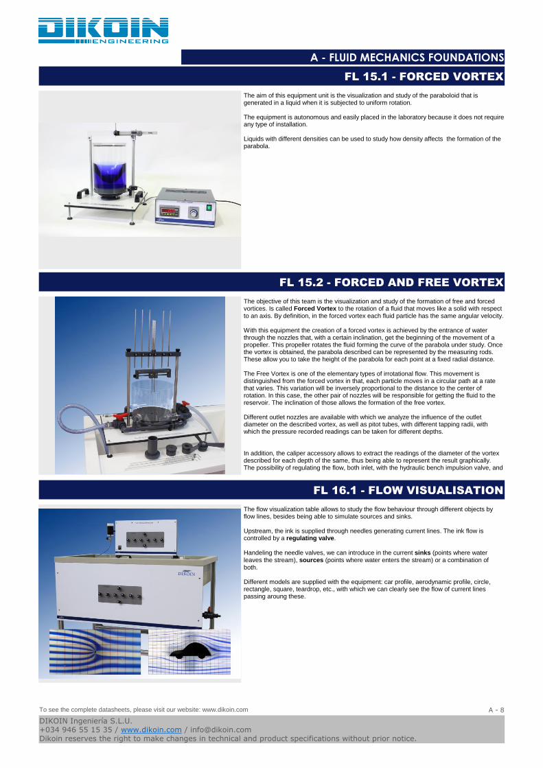
The aim of this equipment unit is the visualization and study of the paraboloid that is generated in a liquid when it is subjected to uniform rotation.
The equipment is autonomous and easily placed in the laboratory because it does not require any type of installation.
Liquids with different densities can be used to study how density affects the formation of the parabola.
FL 15.1 - FORCED VORTEX
The objective of this team is the visualization and study of the formation of free and forced vortices. Is called Forced Vortex to the rotation of a fluid that moves like a solid with respect to an axis. By definition, in the forced vortex each fluid particle has the same angular velocity.
With this equipment the creation of a forced vortex is achieved by the entrance of water through the nozzles that, with a certain inclination, get the beginning of the movement of a propeller. This propeller rotates the fluid forming the curve of the parabola under study. Once the vortex is obtained, the parabola described can be represented by the measuring rods. These allow you to take the height of the parabola for each point at a fixed radial distance.
The Free Vortex is one of the elementary types of irrotational flow. This movement is distinguished from the forced vortex in that, each particle moves in a circular path at a rate that varies. This variation will be inversely proportional to the distance to the center of rotation. In this case, the other pair of nozzles will be responsible for getting the fluid to the reservoir. The inclination of those allows the formation of the free vortex.
Different outlet nozzles are available with which we analyze the influence of the outlet diameter on the described vortex, as well as pitot tubes, with different tapping radii, with which the pressure recorded readings can be taken for different depths.
In addition, the caliper accessory allows to extract the readings of the diameter of the vortex described for each depth of the same, thus being able to represent the result graphically.The possibility of regulating the flow, both inlet, with the hydraulic bench impulsion valve, and
FL 15.2 - FORCED AND FREE VORTEX
The flow visualization table allows to study the flow behaviour through different objects by flow lines, besides being able to simulate sources and sinks.
Upstream, the ink is supplied through needles generating current lines. The ink flow is controlled by a regulating valve.
Handeling the needle valves, we can introduce in the current sinks (points where water leaves the stream), sources (points where water enters the stream) or a combination of both.
Different models are supplied with the equipment: car profile, aerodynamic profile, circle, rectangle, square, teardrop, etc., with which we can clearly see the flow of current lines passing aroung these.
FL 16.1 - FLOW VISUALISATION
To see the complete datasheets, please visit our website: www.dikoin.com
Catalogos-Pie19A - 8
DIKOIN Ingeniería S.L.U.+034 946 55 15 35 / www.dikoin.com / [email protected] reserves the right to make changes in technical and product specifications without prior notice.

Logo-DK
A - FLUID MECHANICS FOUNDATIONS
This equipment allows the study of the behavior of fluids in open channels and flow lines that form around different submerged objects.
The service for the experiments is the flowing water. So that the flow lines are visible during the experiments, diluted ink is used in water. This combination of elements with the feature that the channel is completely transparent allows optimal viewing of the flow lines .
Different bodies of landfill and profiles are provided as varied forms.
FL 16.2 - STREAMLINES VISUALIZATION IN A CHANNEL
The objective to be achieved with this equipment is the study of primary pressure losses produced along a pipeline in both laminar and turbulent regimen.
This equipment has a horizontal pipe in which perform readings of the pressure loss produced for different flow rates. It also has, with the possibility to study the friction in the same pipe for both laminar and turbulent regime.
To get this last, we feed pipe from a tank of constant height. For readings of upstream and downstream of the pressure test pipe, we have two differential pressure gauges, one of water and other digital.
For regulation of the flow use two valves, one located at the begin of the installation and another place at the exit of the test pipe. The flow through into the pipe is measured using .
FL 17.1 - PIPE FRICTION
The objective to be achieved with this equipment is the study of the primary losses of load that occur along a pipe, in two regimenes: laminar and turbulent.
This equipment counts on a vertical pipe, in which we make the readings of the loss of load produced for different flows; Flow rates that we obtain through the regulating valve with which the equipment counts.
The study of the different regimes is achieved by modifying the way in which the water reaches the test pipe, so that, in order to achieve the laminar regime, the pipe is fed from a tank of constant height while for the turbulent regime the supply will be made directly from the water supply equipment.
For the readings of upstream and downstream pressures of the test line, we have two differential pressure gauges, one of water and one of mercury.
Measurements of the flow rates obtained with the control valve are performed using the supplied test tube or the volumetric reservoir of the hydraulic bank (required), which also studies the relationship between the pressure drop and the fluid velocity.
FL 17.2 - LOSSES IN PIPES
To see the complete datasheets, please visit our website: www.dikoin.com
Catalogos-Pie19A - 9
DIKOIN Ingeniería S.L.U.+034 946 55 15 35 / www.dikoin.com / [email protected] reserves the right to make changes in technical and product specifications without prior notice.
Logo-DK
A - FLUID MECHANICS FOUNDATIONS
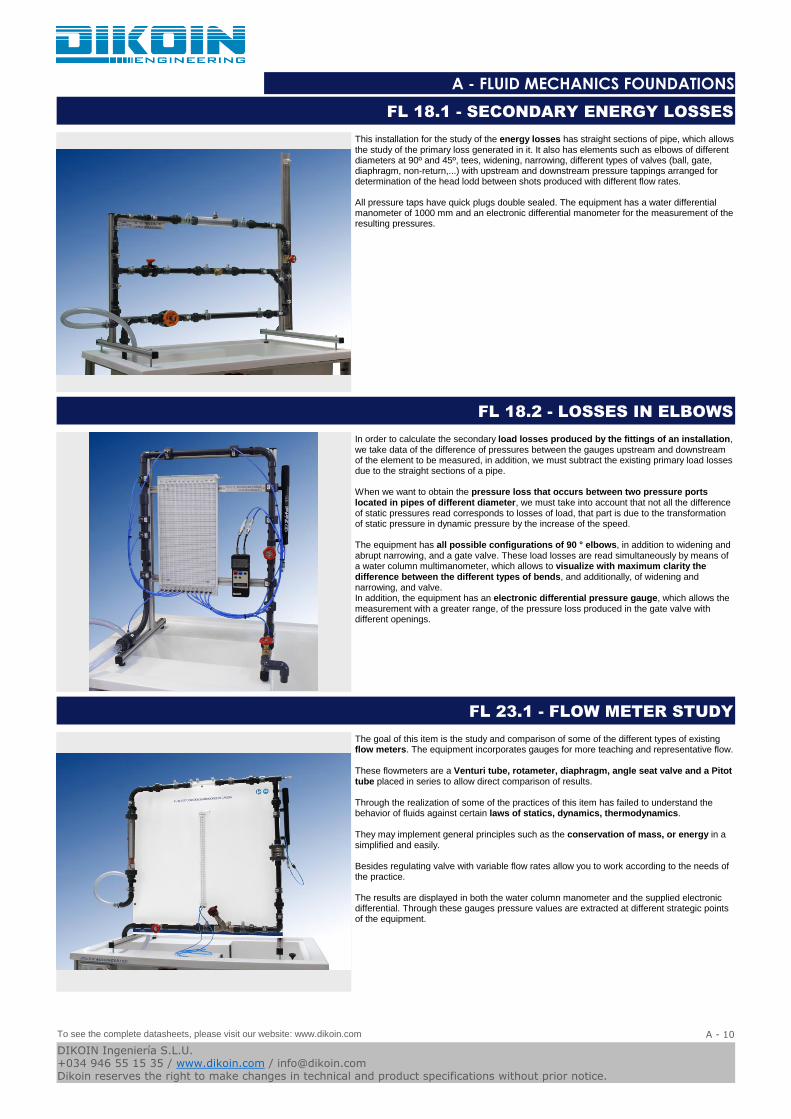
This installation for the study of the energy losses has straight sections of pipe, which allows the study of the primary loss generated in it. It also has elements such as elbows of different diameters at 90º and 45º, tees, widening, narrowing, different types of valves (ball, gate, diaphragm, non-return,...) with upstream and downstream pressure tappings arranged for determination of the head lodd between shots produced with different flow rates.
All pressure taps have quick plugs double sealed. The equipment has a water differential manometer of 1000 mm and an electronic differential manometer for the measurement of the resulting pressures.
FL 18.1 - SECONDARY ENERGY LOSSES
In order to calculate the secondary load losses produced by the fittings of an installation, we take data of the difference of pressures between the gauges upstream and downstream of the element to be measured, in addition, we must subtract the existing primary load losses due to the straight sections of a pipe.
When we want to obtain the pressure loss that occurs between two pressure ports located in pipes of different diameter, we must take into account that not all the difference of static pressures read corresponds to losses of load, that part is due to the transformation of static pressure in dynamic pressure by the increase of the speed.
The equipment has all possible configurations of 90 ° elbows, in addition to widening and abrupt narrowing, and a gate valve. These load losses are read simultaneously by means of a water column multimanometer, which allows to visualize with maximum clarity the difference between the different types of bends, and additionally, of widening and narrowing, and valve.In addition, the equipment has an electronic differential pressure gauge, which allows the measurement with a greater range, of the pressure loss produced in the gate valve with different openings.
FL 18.2 - LOSSES IN ELBOWS
The goal of this item is the study and comparison of some of the different types of existing flow meters. The equipment incorporates gauges for more teaching and representative flow.
These flowmeters are a Venturi tube, rotameter, diaphragm, angle seat valve and a Pitot tube placed in series to allow direct comparison of results.
Through the realization of some of the practices of this item has failed to understand the behavior of fluids against certain laws of statics, dynamics, thermodynamics.
They may implement general principles such as the conservation of mass, or energy in a simplified and easily.
Besides regulating valve with variable flow rates allow you to work according to the needs of the practice.
The results are displayed in both the water column manometer and the supplied electronic differential. Through these gauges pressure values are extracted at different strategic points of the equipment.
FL 23.1 - FLOW METER STUDY
To see the complete datasheets, please visit our website: www.dikoin.com
Catalogos-Pie19A - 10
DIKOIN Ingeniería S.L.U.+034 946 55 15 35 / www.dikoin.com / [email protected] reserves the right to make changes in technical and product specifications without prior notice.
Logo-DK
A - FLUID MECHANICS FOUNDATIONS
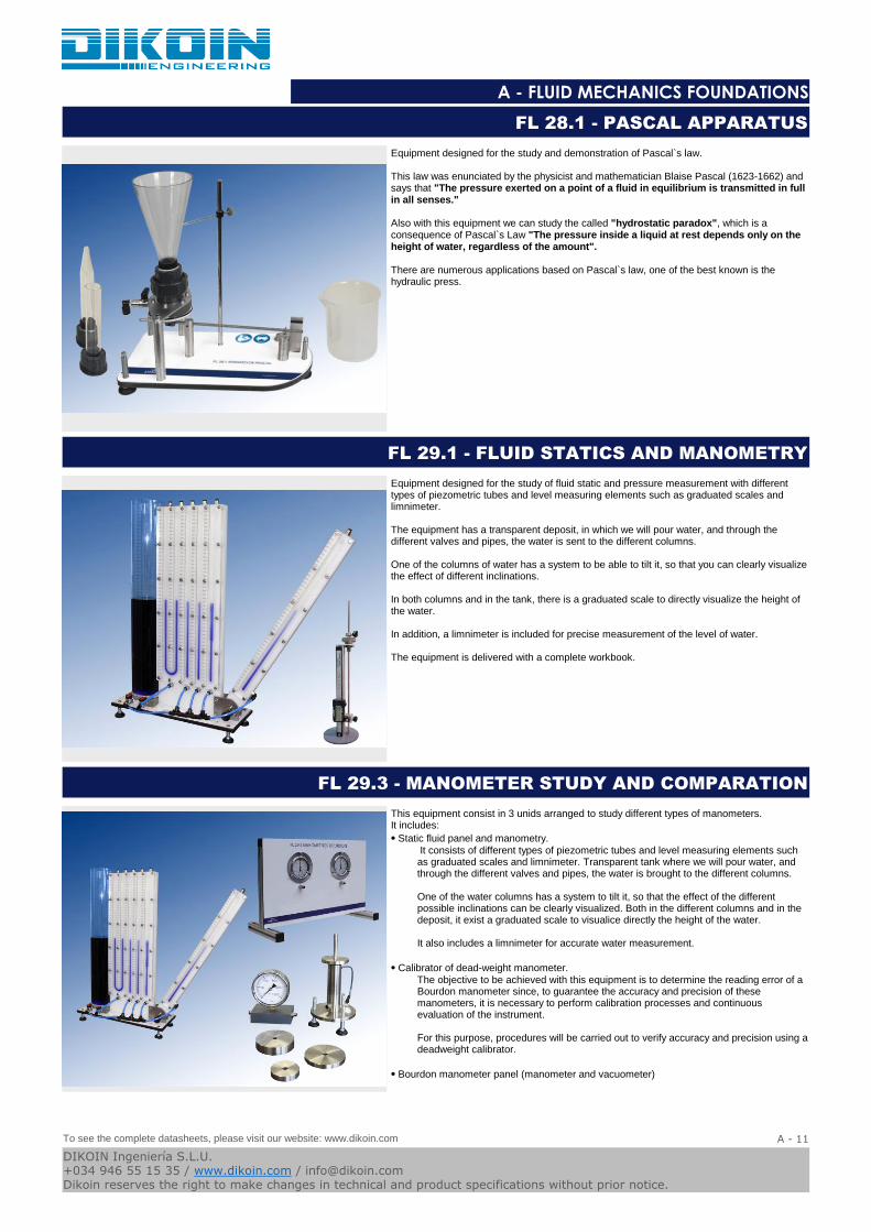
Equipment designed for the study and demonstration of Pascal`s law.
This law was enunciated by the physicist and mathematician Blaise Pascal (1623-1662) and says that "The pressure exerted on a point of a fluid in equilibrium is transmitted in full in all senses."
Also with this equipment we can study the called "hydrostatic paradox", which is a consequence of Pascal`s Law "The pressure inside a liquid at rest depends only on the height of water, regardless of the amount".
There are numerous applications based on Pascal`s law, one of the best known is the hydraulic press.
FL 28.1 - PASCAL APPARATUS
Equipment designed for the study of fluid static and pressure measurement with different types of piezometric tubes and level measuring elements such as graduated scales and limnimeter.
The equipment has a transparent deposit, in which we will pour water, and through the different valves and pipes, the water is sent to the different columns.
One of the columns of water has a system to be able to tilt it, so that you can clearly visualize the effect of different inclinations.
In both columns and in the tank, there is a graduated scale to directly visualize the height of the water.
In addition, a limnimeter is included for precise measurement of the level of water.
The equipment is delivered with a complete workbook.
FL 29.1 - FLUID STATICS AND MANOMETRY
This equipment consist in 3 unids arranged to study different types of manometers.It includes:
⦁ Static fluid panel and manometry.
It consists of different types of piezometric tubes and level measuring elements such as graduated scales and limnimeter. Transparent tank where we will pour water, and through the different valves and pipes, the water is brought to the different columns.
One of the water columns has a system to tilt it, so that the effect of the different possible inclinations can be clearly visualized. Both in the different columns and in the deposit, it exist a graduated scale to visualice directly the height of the water.
It also includes a limnimeter for accurate water measurement.
⦁ Calibrator of dead-weight manometer.The objective to be achieved with this equipment is to determine the reading error of a Bourdon manometer since, to guarantee the accuracy and precision of these manometers, it is necessary to perform calibration processes and continuous evaluation of the instrument.
For this purpose, procedures will be carried out to verify accuracy and precision using a deadweight calibrator.
⦁ Bourdon manometer panel (manometer and vacuometer)
FL 29.3 - MANOMETER STUDY AND COMPARATION
To see the complete datasheets, please visit our website: www.dikoin.com
Catalogos-Pie19A - 11
DIKOIN Ingeniería S.L.U.+034 946 55 15 35 / www.dikoin.com / [email protected] reserves the right to make changes in technical and product specifications without prior notice.

Logo-DK
A - FLUID MECHANICS FOUNDATIONS
Equipment designed for the study of the properties of fluids. A wide range of practices and experiences can be realized, some of which are listed below:
⦁ Measurement of densities using densimeters.
⦁ Measurement of densities using a pycnometer.
⦁ Study and demonstration of the capillarity in tubes.
⦁ Study and demonstration of capillarity between plates.
⦁ Determination of viscosity.
⦁ Measurement of atmospheric pressure using an anaerobic barometer.
⦁ Law of Archimedes.
FL 30.1 - FLUID PROPERTIES
Pumps are included in a piping system to convert mechanical energy into hydraulic energy. This additional energy allows the transmission of a fluid from one place to another when it is not feasible to flow by gravity, raise it to a certain height on the pump or recirculate it in a closed system. In general, the effect of a pump on a system is to increase the total energy by an amount H.
The efficiency of a pumping system depends in great extent on the placement of different pump configurations both in series and in parallel according to the needs of the system.
In addition, the flow regulating valve manages to operate the pump at different points of operation, with we obtain experimentally its working curves. These work curves can be compared with those supplied by the manufacturer, as well as those obtained by mathematical calculation.
With this equipment it is intended to carry out a large part of the operations of both commissioning and of operation and regulation required in a pumping installation. In addition, the characteristics of a pump operating individually and in groups will be studied.
FLB 03.1 - SERIES AND PARALLEL PUMP MODULE
Pumps are included in a pipe system to convert mechanical energy into hydraulic energy. This additional energy allows the transmission of a fluid from one place to another when it is not feasible to flow by gravity, raise it to a certain height on the pump or recirculate it in a closed system. In general, the effect of a pump on a system is to increase the total energyby an amount H.
In the case of the centrifugal pump its operation is based on the input of the fluid through the center of the impeller, which has blades for conducting the fluid, and as a result of the centrifugal force is driven outwards. There it is collected by the pump casing, which by the outline its shape leads it to the outlet pipes or to the next impeller.
With this equipment is intended to study the characteristics of a pump running individually at different speeds of rotation. This is possible thanks to the frequency inverter that incorporates which modifies the working speed of the pump according to the case study.
In addition, the flow regulating valve manages to operate the pump at different points of operation, which we experimentally obtain its working curves. These work curves can be compared with those supplied by the manufacturer, as well as those obtained by mathematical calculation.
FLB 03.2 - PUMP CHARACTERISTICS MODULE
To see the complete datasheets, please visit our website: www.dikoin.com
Catalogos-Pie19A - 12
DIKOIN Ingeniería S.L.U.+034 946 55 15 35 / www.dikoin.com / [email protected] reserves the right to make changes in technical and product specifications without prior notice.

Logo-DK
A - FLUID MECHANICS FOUNDATIONS
The objective to reach with this uncomplicated module is the study in depth of the equation of Bernoulli and its demonstration.
This apparatus is based on Bernoulli`s principle, which describes the behaviour of a laminar flow moving throughout a conduit and considers that in an ideal situation, for a fluid (without viscosity nor friction) in a regime of circulation through a closed conduit, the energy remains constant throughout its route.
The equipment comes with a Venturi tube, implemented to carry out experiments for the demonstration of the theory based on the theorem of the conservation of mechanical energy.
The regulation valve allows to work with a variety of flow rates giving rise to different scales in differential pressure.
The pressure results are shown in the multi-tube manometers installed in the equipment. Therefore, the readings of pressure along the conduit can be obtained quite easily.
The measure of flow rates is carried out thanks to the volumetric tank in the hydraulic bench (required), which also enables the study of the relation between the pressure drop and the speed of the fluid.
FLB 06.2 - BERNOULLI`s THEOREM
With this equipment is intended to study and demonstrate the operation of a hydraulic ram, a system by which we can raise a liquid to a height higher than the height of supply, without external energy input.
The ram uses more water in its process than the one that drives, the proportion driven is between 10-15%. But as it operates all the time, this small amount will always be useful.
The practices and experiences that will be realized with this equipment are the following:
⦁ Visualization and analysis of the water hammer phenomenon caused by the closing
of a valve.
⦁ Study and understanding the operation of the hydraulic ram.
⦁ Obtaining the flow ratio.
⦁ Water hammer efficiency.
FLB 09.2 - HYDRAULIC RAM STUDY
This equipment is designed for the study of the pressure exerted by a fluid on a surface submerged in it.
The shape of the sector or quadrant that is submerged into the water ensures that the only pressure exerted by the water on its surface goes to the lower rectangular vertical surface. During the experiment, a counterbalance is placed
A ruler shows the water height from the lower point of the submerged rectangular face on which the phenomenon is studied.
To avoid any friction that deflects the measurement, the entire quadrant system and its lever arm (where we place the counterbalance weights) are supported on bearings with glass spheres, which clearly increase the accuracy of the test.
FLB 10.1 - HYDROSTATIC PRESSURE
To see the complete datasheets, please visit our website: www.dikoin.com
Catalogos-Pie19A - 13
DIKOIN Ingeniería S.L.U.+034 946 55 15 35 / www.dikoin.com / [email protected] reserves the right to make changes in technical and product specifications without prior notice.

Logo-DK
A - FLUID MECHANICS FOUNDATIONS
This equipment is designed to prove the theoretical expressions that determine the force applied by a jet stream on different types of impact plates.
The equipment, operating on the hydraulic bench, shows to perfection the impact of the jet stream on the target plate under study, thanks to its transparent case.
The bubble level allows the correct levelling of the equipment for improving the results accuracy.
HIGHLIGHTS
⦁ Fast and simple replacement of target plates.
⦁ Connectivity to a hydraulic bench
⦁ Four different target plate types: 30º, 90º, 120º and 180º.
FLB 11.1 - JET STREAM FORCES
There are different methods to measure the pressure, for example by means of the pressure gauges.
One is due to consider that the pressure can be expressed in reference to an arbitrary origin. The scale of the pressure gauge indicates zero when the measurer is open to the atmospheric pressure and, over zero, is calibrated generally in pascals (as in the case of the pressure gauge provided with this equipment) or in other units of pressure.
The objective that is tried to reach with this equipment is to determine the read error of a Bourdon pressure gauge, since, to guarantee the exactitude and precision of these pressure gauges, it is necessary to make processes of calibration and continuous evaluation of the instrument.
For that procedures will be made destined to verify this exactitude and precision using a dead weight calibrator.
FLB 13.1 - DEAD WEIGHT CALIBRATOR
The goal for this apparatus is to reproduce the experiment designed by Osborne Reynolds visualizing laminar, transitional and turbulent flows, and establishing the Reynolds number that corresponds to each one of them.
The equipment is designed to be operated on the hydraulic bench (FL01.4, FL FL01.5 or 01.6).
A flow of water mixed with ink in a certain dose is pushed through a needle placed at the entry into a glass tube.
Depending on the flow rate passing through the tube, it can be seen how the ink mixes or not with the water, making a neat line in the case of a laminar flow, or getting mixed with the water in transitional regimes. When it gets to the point of turbulence, the ink will be thoroughly mixed with the water, and it will not be possible to tell them apart.
FLB 14.2 - OSBORNE REYNOLDS DEMONSTRATOR
To see the complete datasheets, please visit our website: www.dikoin.com
Catalogos-Pie19A - 14
DIKOIN Ingeniería S.L.U.+034 946 55 15 35 / www.dikoin.com / [email protected] reserves the right to make changes in technical and product specifications without prior notice.

Logo-DK
A - FLUID MECHANICS FOUNDATIONS
The aim of this training unit is the study and comparison of some of the different types of existing flow meters. This equipment is intended for groundwork and it is implemented with the most didactic and widely-used flow meters.
In our case, the flow meters chosen are a venturi, a rotameter and a diaphragm placed in series will allow direct comparison of results.
Through the realization of some of the practices of this team has failed to understand the behavior of fluids against certain laws of statics, dynamics, thermodynamics. They may implement general principles such as the conservation of mass, or energy in a simplified and easily.
Besides regulating valve with variable flow rates allow you to work according to the needs of the practice.
The pattern of the flow measurements are made using the volumetric tank of the hydraulic bench (required), so that the relationship between the pressure drop and the fluid velocity is also studied.
Pressure readings are displayed on a multi-tube manometer 8 outlets through which values are extracted on 8 strategic points of the equipment.
FLB 23.1 - FLOW METER DEMONSTRATION
Additional accessory for hydraulic bench consisting of a DN25 pipe section and an electronic flow meter. The set has a total measurement of 500mm.
The flowmeter has a digital display where the flow that circulates through the hydraulic circuit is visualized. Its installation in a hydraulic bench allows to obtain measurements in a much faster and more precise way.
The installation of this accessory on the bench is done by means of threaded links, which allows it ti be done in a simple, fast and safe way.
FLQ-500-200lm - ELECTRONIC FLOW METER FOR HYDRAULIC BENCH
Additional accessory for hydraulic bench consisting of a DN08 pipe section and an electronic flow meter. The set has a total measurement of 500mm.
The flowmeter has a digital display where the flow that circulates through the hydraulic circuit is visualized. Its installation in a hydraulic bench allows to obtain measurements in a much faster and more precise way.
The installation of this accessory on the bench is done by means of threaded links, which allows it ti be done in a simple, fast and safe way.
FLQ-500-30lm - ELECTRONIC FLOW METER 30l/min FOR HYDRAULIC BENCH
To see the complete datasheets, please visit our website: www.dikoin.com
Catalogos-Pie19A - 15
DIKOIN Ingeniería S.L.U.+034 946 55 15 35 / www.dikoin.com / [email protected] reserves the right to make changes in technical and product specifications without prior notice.

Logo-DK
A - FLUID MECHANICS FOUNDATIONS
Additional accessory for Dikoin hydraulic bench, adapting the hydraulic circuit to connect additional equipment.
The 500mm section, supplied with the equipment, can be easily replaced due to the connections with threaded links. No tools are required for installation.
FLZ.T500 - ACCESSORY ADAPTER FOR HYDRAULIC BENCH
To see the complete datasheets, please visit our website: www.dikoin.com
Catalogos-Pie19A - 16
DIKOIN Ingeniería S.L.U.+034 946 55 15 35 / www.dikoin.com / [email protected] reserves the right to make changes in technical and product specifications without prior notice.