a footy design by roger stolleryfooty.rcsailing.net/awk/awk-article.pdf · a footy design by roger...
TRANSCRIPT
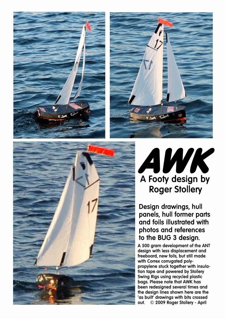
A Footy design byRoger Stollery
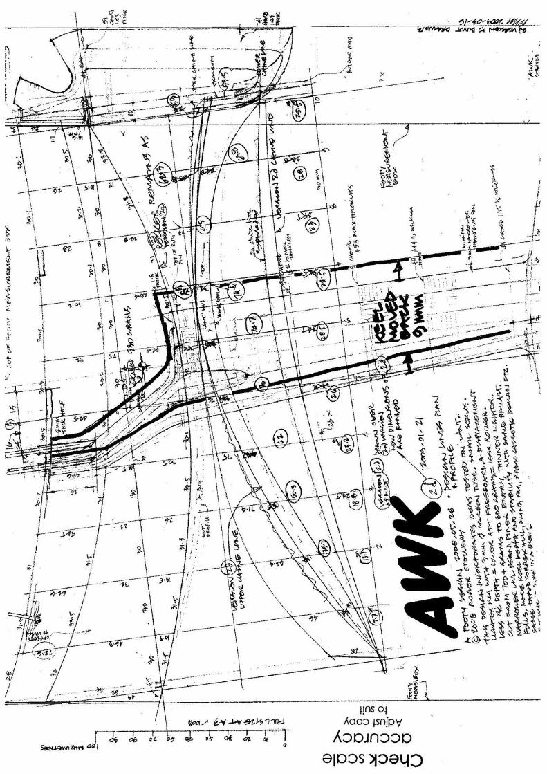
Design drawings hullpanels hull former partsand foils illustrated withphotos and referencesto the BUG 3 designA 500 gram development of the ANTdesign with less displacement andfreeboard new foils but still madewith Correx corrugated poly-propylene stuck together with insula-tion tape and powered by StollerySwing Rigs using recycled plasticbags Please note that AWK hasbeen redesigned several times andthe design lines shown here are thelsquoas builtrsquo drawings with bits crossedout copy 2009 Roger Stollery - April
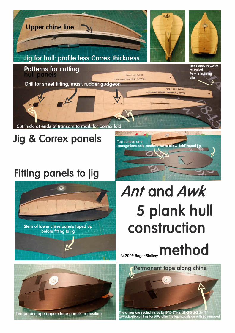
Jig for hull profile less Correx thickness
Patterns for cuttinghull panelsDrill for sheet fitting mast rudder gudgeon
Upper chine line
Cut lsquonickrsquo at ends of transom to mark for Correx fold
This Correx is wastere-cycledfrom a buildingsite
Jig amp Correx panels Top surface andcorrugations only carefully cut to allow lsquofoldrsquo round jig
Fitting panels to jig
Stem of lower chine panels taped upbefore fitting to jig
Temporary tape upper chine panels in position
Permanent tape along chine
and5 plank hull
construction
methodcopy 2009 Roger Stollery
The chines are sealed inside by EVO-STIKrsquos lsquoSTICKS LIKE SHT lsquo(wwwbostikcom) as for BUG after the taping outside with jig removed
Please note that this is for reference and to explainthe construction of the hull jigThe hull jig panel patterns shown on the otherdrawing are lsquoas builtrsquo and should be followed inpreference to any dimension on these sections
Moulding foilsIntroductionThe moulding process for foils is in comparatively easy and quick compared to making arudder out of timber The advantage is that in just a few minutes a beautifully shapedand finished moulding that needs no painting wont warp delaminate and will remainclose to the desired accurate cross section This is important to reduce the drag particu-larly for classes with long fins Moulding is an ideal club activity where one mould can beused over and over again and make the investment of time in making the mould veryworthwhileMoulding a rudderThe example shown is a small transom hung rudder for a Footy Assuming that you havemade or borrowed a mould the creation of which will be covered later the first thing isto wax the mould with a release agent such as Mirror Glaze Mix a small quantity of pol-yester gelcoat resin and carefully paint onto the polished surfaces of the mould If anyresin gets onto the centre line surfaces wipe it off with a cloth wrapped around your fin-ger Whilst allowing that to cure cut two fabric panels one for each side from the car-bon reinforcing cloth and a small piece of Cormat to form a solid section at the topWhen the gel coat is cured paint the rudder surfaces with polyester laminating resin andlay in the carbon fibre carefully aligning the cloth with the front and top of the rudderCarefully stipplepaint the surface with the brush to bring up the resin from below andadd more resin where it looks dry painting it from the more resin rich areas if possibleRepeat on the other side Wet up on a piece of polythene the small Cormat panel andstitch in a waxed 16 swg wire pin along the line on that pattern and lay in one half ofthe mould This will form a hole for the pintle Add a little resin all round the edges ofboth halves Dont worry about resin getting onto the centreline surfaces this time be-cause when these are carefully placed together and bolted up the resin will besqueezed out and will appear as flash to be cleaned off the edges of the moulding Thispart always appears to be a bit of a messy crude process Add a few clamps to ensurethat the two halves are in good contact along the edgesFinishing the rudderAfter curing remove the rudder from the mould Start by twisting bending and distortingthe mould with a bit of force and the cracking sounds will let you know that the mould-ing is being released Opening up the mould is the most exciting and satisfying part Onenew moulder recently described it as like giving birth After this relatively crude processa beautifully light polished product appears Clean the flash from the edges with a pairof scissors and finally a sanding block
Making a mould
Design of foilsNow assume that you want a special rudder shape or cross section and need to pro-duce your own mould It is not difficult but it is time consuming The design drawing is thestarting point for making a plug for the mould because this will be made of 116 ply-wood Each ply is 053mm thick so as well as the profile the buttock lines are drawn053mm apart from the centreline thin vertical section slices through the rudder asshown adjacent Briefly this is done by drawing a NACA 0006 section shape on a 100mmlength chord but with the vertical scale drawn 10 times the true scale giving an exag-gerated curve This is then photocopied down to the various chord lengths for suitablesections of your rudder Over these section copies draw parallel (buttock) lines 53mmfrom the centreline Where these cut the curve sets points that make up the buttock lineshape on the profile This can be hand drawn as shown adjacent The maximum thick-ness is less than 32mm overall so each half can be shaped from just one layer of plyMaking the plugCut the ply to the rudder profile The grain of the centreline layer MUST be across the rud-der Repeat for the other half Most important for later registration of the two halves isdrilling two 15mm holes towards the ends of the maximum thickness line Make a sup-port block the same profile shape as the rudder and drill this too with registration holesUse 16mm stainless steel wire to pin the ply down to the support block Sand the ply untilthe glue lines match the buttock lines Glue the plug halves to a flat Formica baseplateprojecting about 25mm beyond the rudder profile Make sure that the very flexible ta-pered ply edges are held down flat to the baseplate Drill registration holes in the base-plates and bond them temporarily to a flat melamine covered chipboard Drillregistration holes and push the pins down just below the rudder surface Fill these bigholes with plastercine and finish flush Do not worry if there are a few bits of the cen-treline ply missing that you cannot replicate with plastercine Only make sure that thereare NO bumps or projections Hollows become bumps in the mould which can easily besanded offMaking the mouldWax the surfaces with an old-fashioned bees wax like Simoniz wax for cars Spread thewax with a cloth in a circular motion to get it even and then polish it off with a cleancloth Repeat until there are 5 applicationsRepeat the moulding process described for moulding the rudder but with two thin poly-ester gel coats preferably in different colours and two layers of carbon either side of a2mm Cormat layer After curing remove the Formica from the melamine base removethe pins and cut one set down in length to locate the Formica layers together Clamp
up and drill 2 bolt holes for bolts that will hold the mould parts together Now remove the plug This may be tricky if any resin hasgot under the edge of the plug Go round the edges carefully and chip away this resin so that the whole profile of the ply isshowing Bend twist and distort the mould and some part of the plug will release Slide a thin flexible piece of plastic under thisreleased bit and gently work it under the remaining parts of the plug It wont look a good surface but the finish is achieved bysanding with progressively finer wet and dry sandpaper up to at least 1200 grade and preferably 2000 until it is perfectly smoothwith all bumps removed Polish the surfaces with T-cut until it is a mirror finish Patience and hard work is required but it is worth itin the end as all the subsequent mouldings will have this fine finish This finishing process wants to be done as soon as possibleafter moulding as the resin is much softer and less hard workMouldsSome clubs have moulds that can be borrowed so if your club has no moulding expert ask around as there is sure to be some-one who can help you enjoy the pleasures of moulding
Sail plans as used in 2009 These Swing Rigs apply also to ANT The 500mm amp 300mm hoist rigs also apply to BUG 3 and are the starter set for covering all winds strengths
550mm luff rig is for better performance in the lightest airs
372 luff rig is least necessary asANT amp AWK are powerful
enough to change directly from 500 to the 300 hoist rig
This rig detail is out of order It supercedesaddsto the information on rigs on page 4
copy 2009 Roger Stollery - 2009-11-29
Sheeted in Sheeted out
Standard switch cut level with plate
Cassette Radio InstallationThe principle shown here is that the radio gear is not fixed to the boat but to a thin flatplate just bigger than the 70 x 60 mm long hatch shape and taped to the deck Theservos are mounted by bolting to the underside of the plate which is located in the deckby the Correx piece cut out for the hatch The servos operate through the plate and arewaterproofed by a silicone grease laden kitchen sponge washer under the horn Thesheet is operated by a Powerlever which is shown operating on the BUG above Thesheet is attached to a ring which slides on the Powerlever when sheeting out it travels tothe full extent of the lever to give the travel for the running trim and sheeting in the ring ispulled towards the servo so increasing power on the sheet without strain on the servo Inthe BUG cassette there are two basic servos pulling 25kgcm or so
With this design principle and the balance of forces in the Swing Rig it is possible to usemuch smaller and lighter servos The later ANT AWK amp ICE hulls use the cassette designbelow in the same 70 x 60mm deck hole with two HD1800A 8 gram servos with a stallload of 13 kgcm available from Howes Models See servo details on wwwchdhk Theseare just bonded to the underside of the plate with lsquoSticks Like Shtrsquo as used to seal theinside of the Correx hull chines A standard switch has the switch projection cut level withthe top of the plate It is also stuck to the underside operated through a slot in the plateand covered with tape to waterproof it There is no readable detail drawing available todate but the photos below show the general arrangement used on the later designs ThePowerlever is 08mm or 21 swg stainless steel wire The RX shown is used with the Planet T5TX also from Howes Models The 48v Ni-MH 120mAh 15 gram rechargeable battery packfrom The Component Shop is Velcroed to the bottom of the servos In light conditions thecharge will last about an hour copy 2010 Roger Stollery
Simple soft sails for small rigsAs an alternative to cutting panels and forming seams in drawingfilm very adequate small sails can be made using soft sail mate-rial just folded over to form double sided sails These are idealfor the smallest models like Footys up to BOTTLE boats with asail area of 600 square inches on which this idea was developedThey have even be used for light weather jibs for Marbleheadand lsquoArsquo boats with additional film reinforcing the leech
Soft materialsSuch soft materials include any sort of thin plastic bag materialssuch as dry cleanerrsquos bags bin bags shopping bags freezer bagsetc The massive choice of colours allows a bit of fun As thisthin soft material is flexible and stretchy it is possible to createfullness within the sail very simply without the need for panelsor great DIY skills The thin material immediately forms a slightcurve where folded over and held with a bit of tension It allowsa very good lsquoautomaticrsquo shape to form in the luff of jibs andmainsails from just a flat sheet However to achieve this it doesneed to be set up carefully as described below
Cutting the sailsAfter selecting the material fold it over with the fold forming thefront edge of the sail Place on a hard laminate or similar cuttingsurface and tape it down with only just enough tension to get ridof the major wrinkles Either mark the plan of the sail on the ma-terial or place a pattern of the sail shape onto it with the straightluff on the fold line This pattern can be made from cardboard orthin ply so that the material can be sealed with a hot solderingiron along the back edge With such soft material the leech shapeneeds to be a series of straight lines between corners andor bat-tens Cut the foot and head shapes with a sharp knife but donrsquotseal the two surfaces together along these lines
Finishing the mainsailAdd reinforcement tape such as electrical insulation tape to thecorners as shown in the photographs with the number of layersdependant on the forces generated from the boat Two layers issufficient for Footy sails Fit eyelets to the bottom corners mak-ing sure that the tack eyelet allows the mast to fit within thesleeve in front of it An important part of the design is a widehead shape at right angles to the mast Stick the tape along thetop of the leech and fold it over the head and down the otherside Repeat on the other side of the sail Battens need only befitted to one side They can made from any flexible thin plasticfixed with double sided tape and reinforced by tape to the sail atthe front end and around the aft end of sail
Tack
Clew
Head
Finishing the jibRepeat sticking on corner reinforcements and fit the eyelet forthe clew but donrsquot add the eyelets to the tack or head until theluff line is fitted to take the rig forestay tension Use a light (6 ndash20 kg) Dyneema line and make a loop at the bottom to go insidethe two sail surfaces and round the tack eyelet before you closethat up Thread the line up the luff using a bodkin or thin wireloop and pull close to the luff before fitting the head eyelet Tem-porarily tape the tack down remove wrinkles in the luff and ap-ply a bit of tension in the luff line Tie a single overhand figureof eight or other stopper knot in the luff line about 10mm abovethe head Apply more tension to the line and tape that downMake a loop passing through the head eyelet and with a cigarettelighter create a blob at one end Pass this round the luff lineabove the stopper knot and tie a half hitch back on the loopCarefully pull tight so that the blob and the stopper knot are to-gether Repeat with the other end of the loop and adjust thelength of the loop such that it is only just slack when the luff lineis taut Cut the end of the loop line about 4mm from the knot andburn the end back close to the knot This will keep the fullness inthe luff of the sail when the luff lineforestay is under tension
Setting up the sail on the rigThe photos show a simple swing rig for a Footy where the mastis fixed and the yard rotates around it The 3mm yard spars aresimply joined with 2mm bent wire and held against the upwardpressure of the sails by a small PTFE block bonded to the mastThe camber in the mainsail is fully adjustable at both top andthe bottom in the normal model yachting tradition with a loosefoot fixed to a boom or yard spar at the clew with a simple bentwire adjuster There is no spar as such at the top but a large125mm diameter wire headstick rotating about the mast allowsthe head of the sail to be fixed at the aft corner in a suitable loca-tion along the headstick to create or remove camber at the top ofthe sail The fullness created here allows the mast to bend withinthe sleeve without creating major creases as the wind increasesThe photos show connection to the headstick by the tape rein-forcement mentioned above which can be adjusted by slittingthe tape or shortening the slit with more tape to get a beautifulshape of any degree of fullness all the way up the sail
Adjusting the Swing Rig tensionsThis design of Swing Rig has a magic balance of forces whichonly requires the adjustment of the bowsie on the jib luff line tosuit different wind strengths The design concept automaticallykeeps perfect tension balance between the main and jib leechesThe design principles of this rig are shown in the diagram andcan be applied to a rig of any size
PivotPivot
13area
23area
Jib foot20-25
Magic balancing tensions in the sails
The Humble Bowsie by Roger StolleryUp to the introduction of DYNEEMA polyester line was used for running rigging and this had arelatively coarse texture and so did not slip through bowsies like the typical plastic ones shown inthe diagram Also polyester was relatively easy to thread by creating a point on the end aftermelting with a cigarette lighter This is the traditional form of line adjuster as used for decades onmodels tent lines etcWhen superpolyethylene came along as DYNEEMA or SPECTRA it was immediately favoured be-cause for the same breaking strain it was a lot thinner and was very soft smooth and silky so re-ducing windage and going through fairleads with less friction However this gave some problems itslipped through traditional bowsies and cigarette lighter blobs could not be sharpened to gothrough small holes So something new was required to solve these problems Also continuing theobjective to reduce windage for jib halyards etc I wanted something more aerodynamic with lessdrag The result is the design shown to scale compared to the traditional form shown below
My solution was to reject plastic even when fibre filled because once the bowsie wears or slips ithas a reduced load capacity The Stollery bowsie uses fishermansrsquo knotting experience of achievingfriction by going round something rather than through it The bent wire bowsie is quick and easy tomake and thread The blobbed Dyneema goes through the big wire eyes easily and the linecannot wear away the bowsie It can be made with round nosed pliers or better round the jigshown on the jig diagramrsquo which is also very easy to make just 2 stainless steel pins bonded withepoxy into a metal plate close to its edge A 5mm diameter plastic ball allows fingers to grip thebowsie but not the line The design was developed in the late 90s for the BOTTLE boat using 08 mmstainless steel rigging wire This technology is now used for general applications on both bigger andsmaller boatsAs an alternative to the ball for gripping the bowsie it can be achieved more simply and with evenless drag by bending projecting ends of the eyes at right angles forming the contact with thefingers This idea has great flexibility by using different wire diameters to suit loads It can bethreaded with extra turns round the wire to suit lines which need to be adjustable but which are notcontinuously loaded You can adjust the number of turns so that the line can flap around and notloosen
BOTT
LE b
oat b
owsie
with
fish
ing
ball
as th
e lsquog
riprsquo
Wire bowsie jig
File end of ss wire
Bend 1
Bend 2Hold the first eyeat right angles withthe end downwards
Cut and file end
lsquoBlobrsquo formed by melting with a cigarette lighter
Low dragwire bowsieThread bowsiescarefully alwaysgoing in orcoming out ofthe lsquoeyesrsquo in thesame way Finishby tying just singlehalf hitch andpull up againstthe lsquoblobrsquo noneed for glue
Typical plastic bowsies suitable for polyester line
24
2416
Upper 16 mm ss pin 2mm highLower pin 1mm high
Edge of metal flat
08mm (21swg) stainless steel wire for most models even for high loads on Marbleheads Use 056mm (24swg) for Footys etc
Shown here is Ron Thompsonrsquos lsquoDyna Cablersquo 038mm 363kg 80lbs Dyneema fishing line There is a goodrange of breaking strains the 6kg line is incredibly fine
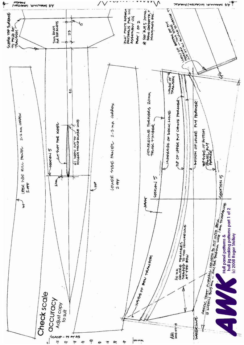
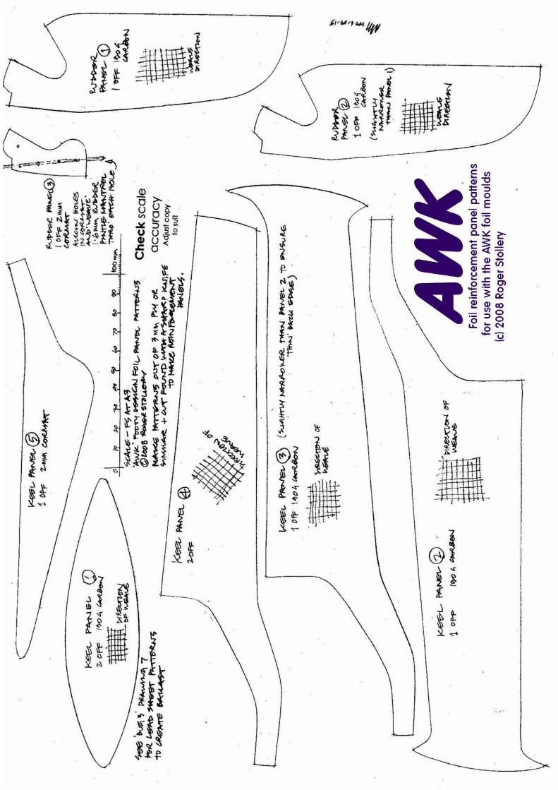