a framework for abstraction and … · i i i i i i i i department of computer architecture and...
TRANSCRIPT

ii
ii
ii
ii
Department of Computer Architecture and Technology
A FRAMEWORK FOR
ABSTRACTION AND VIRTUALIZATION
OF SENSORS IN
MOBILE CONTEXT-AWARE COMPUTING
CandidateBorja Gamecho
Supervisors
Julio Abascal
Luis Gardeazabal
Deposit
May 2015

ii
ii
ii
ii

ii
ii
ii
ii
To my parents.

ii
ii
ii
ii

ii
ii
ii
ii
“The worthwhile problems are the ones you can really solve or help solve, the onesyou can really contribute something to. ... No problem is too small or too trivial if wecan really do something about it.”
Richard Feynman (1918 - 1988)

ii
ii
ii
ii
ii
ii
ii
ii
Acknowledgements
Aprovecho estas líneas para agradecer y recordar a todas las personas y com-pañeros que me han ayudado directa o indirectamente en el desarrollo de estatesis:
En primer lugar, a mis directores Luis y Julio por darme la oportunidadde empezar en el grupo de investigación. Y más importante todavía, por suapoyo y supervisión durante mi etapa de doctorando. Sin vuestra paciencia yconstancia, esta tesis no habría llegado a buen puerto.
Al resto de los miembros de Egokituz, con los que he compartido reunionesy seminarios, por todo lo que he podido aprender de vosotros y vuestro trabajo.En especial me gustaría destacar al "Egoki Team": Amaia, Idoia y Raúl, por losmomentos compartidos durante el desarrollo de Egoki y el proyecto INREDIS,junto a vosotros aprendí el significado de la palabra equipo. No me olvidotampoco de Ana, Carlos, Christian, Edu, Myriam, Nestor, Unai B., Unai M.,Xabi G., Xabi V., Zigor ... por los buenos ratos vividos en el laboratorio 303.
I also would like to express my gratitude to the people of the BIT team inLisbon, and specially to Hugo Silva and Prof. Ana Fred for giving me thechance to do a research stay in their group. André, José, Priscilla, Carlos,David, etc. this thesis would be very different without those months in Lis-bon. You give me the opportunity to challenge myself. Muito obrigado!
A los participantes de los experimentos por dedicarme parte de vuestrotiempo tanto en Lisboa, como en Donosti. En especial a Marcos, MariFe, Ma-ritxin y Ramón por ofrecerse voluntarios para probar el sistema. También a laasociación de jubilados Jatorra por las facilidades y predisposición que habéispuesto durante los experimentos sin esperar nada a cambio.
A los doctorandos y doctores de otros grupos de la facultad que he tenidola suerte de conocer desde que empecé el Máster SIA. Habéis conseguido queel buen humor y las risas se abran paso entre los agobios y deadlines que nohemos dejado de superar. Estoy seguro de que aunque no os mencione unopor uno, acabaremos celebrando esta tesis como se merece.
A mis padres, a mi tía, y a mi cuadrilla al completo por haber estado dispo-nibles cuando os he necesitado y por entenderme cuando he tenido que estarmás ausente.
ii
ii
ii
ii
Borja Gamecho ha sido beneficiario del Programa Predoctoral de Forma-ción de Personal Investigador No Doctor del Departamento de Educación, Po-lítica Lingüística y Cultura del Gobierno Vasco desde el año 2011 al 2014, ha-biendo desarrollado esta tesis durante ese periodo.
Borja Gamecho held a PhD scholarship from the Research Staff TrainingProgramme of the Basque Government from 2011 to 2014. This PhD Thesiswas carried out during the scholarship time.
This work has been supported by the Ministry of Economy and Competi-tiveness of the Spanish Government and by the European Regional Develop-ment Fund (project TIN2014-52665-C2-1).

ii
ii
ii
ii
ABSTRACT
The latest mobile devices available nowadays are leading to the developmentof a new generation of mobile applications that are able to react to context.Context-awareness requires data from the environment, usually collected bymeans of sensors embedded in mobile devices or connected to them throughwireless networks.
Developers of mobile applications are faced with several challenges whenit comes to the creation of context-aware applications. Sensor and device het-erogeneity stand out among these challenges. In order to assist designers, wepropose a layered conceptual framework for sensor abstraction and virtualiza-tion, called Igerri. Its main objective is to facilitate the development of context-aware applications independently of the specific sensors available in the userenvironment. To avoid the need to directly manage physical sensors, a layeredstructure of virtual and abstract sensors is conceived.
Two software components, based on the proposed framework, have beendesigned in order to test Igerri’s robustness. The first one processes the in-formation from the successive sensor layers and generates high-level contextinformation. The second is responsible for managing network aspects andreal time settings. This implementation has been tested using a representativecontext-aware application in different scenarios. The results obtained showthat the implementation, and therefore the conceptual framework, is suitablefor dealing with context information and hiding sensor programming.
9

ii
ii
ii
ii

ii
ii
ii
ii
RESUMEN
Los dispositivos móviles disponibles actuales facilitan el desarrollo de unanueva generación de aplicaciones móviles que son capaces de reaccionar alcontexto. La computación sensible al contexto requiere datos del entorno quenormalmente se obtienen por medio de sensores embebidos en dispositivosmóviles o conectados a ellos a través de redes inalámbricas.
Los desarrolladores de aplicaciones móviles se enfrentan a varios retos paracrear aplicaciones sensibles al contexto. Entre estos retos destaca la necesidadde tratar la heterogeneidad de los sensores y de los dispositivos móviles. Conel fin de ayudar a los desarrolladores, esta tesis propone un marco conceptualpara la abstracción multinivel y la virtualización de sensores, llamado Igerri.Su principal objetivo es facilitar el desarrollo de aplicaciones sensibles al con-texto independientemente de los sensores específicos que se encuentren en elentorno. Para evitar la necesidad de manipular directamente los sensores físi-cos, se ha concebido una estructura multinivel de sensores virtuales y abstrac-tos.
Se han diseñado dos componentes software basados en el marco propuestopara comprobar la robustez de Igerri. El primero procesa la información dela estructura multinivel de sensores y genera información de contexto de altonivel. El segundo es responsable de administrar, en tiempo real, las opcionesde red y la configuración de los sensores. Esta implementación ha sido probadausando una aplicación representativa, sensible al contexto y en diferentes esce-narios. Los resultados obtenidos muestran que la implementación, y por tantoel marco conceptual que le da soporte, es adecuada para tratar la informaciónde contexto y ocultar los problemas de programación de los sensores.
11

ii
ii
ii
ii

ii
ii
ii
ii
LABURPENA
Gaur egungo gailu mugikor puntakoenek inguruneari erantzuteko gai direnaplikazio mugikorren garapenean oinarritzen dira. Testuingurua nabaritzekoingurunearen informazioa behar da, zeina gailu mugikorretan txertatutako sen-tsoreen edo haririk gabeko sareen bitartez biltzen den.
Aplikazio mugikorren garatzaileek erronka askori aurre egin behar izatendiete testuingurua kontuan hartzen duten aplikazioak garatzerakoan. Erronkanagusien artean, sentsoreen eta gailuen heterogeneotasuna izaten dira. Gara-tzaileei laguntzeko asmoz, Igerri izeneko sentsoreen abstrakzio eta birtualiza-ziorako marko kontzeptual bat proposatzen dugu. Bere helburu nagusia, testu-inguruaren aplikazio hautemangarrien garapena erraztea da, erabiltzaileareningurunean dauden sentsore espezifikoak edozein direla ere. Sentsore fisikoakzuzenean manipulatu behar izatea saihesteko, sentsore birtual etaabstraktuen egitura bat asmatu da.
Igerri-ren sendotasuna egiaztatzeko, proposatutako markoan oinarritutakobi software osagai diseinatu dira. Lehenak, sentsore geruzen informazio geru-zak prozesatu eta maila altuko testuinguru informazioa ematen du. Bigarre-nak, sare aukerak kudeatu eta sentsoreen konfigurazioa denbora errealean bu-rutzen ditu. Inplementazio hau testuingurua hautemateko gai eta adierazga-rria den aplikazio batekin egoera desberdinetan frogatu da. Lortutako emaitzekerakusten dute inplementazioa, eta ondorioz marko kontzeptuala ere, apro-posa dela testuinguruaren informazioa erabiltzeko eta sentsoreen programa-zioa ezkutatzeko.
13

ii
ii
ii
ii
ii
ii
ii
ii
Contents
1 Introduction 11.1 Ubiquitous Computing . . . . . . . . . . . . . . . . . . . . . . . . 11.2 Perception and Context-Awareness Computing . . . . . . . . . . 21.3 Virtualization and Abstraction of Sensors . . . . . . . . . . . . . 31.4 Egoki: Ubiquitous Computing in the Egokituz Laboratory . . . 5
1.4.1 Requirements for Egoki Systems . . . . . . . . . . . . . . 61.4.2 Evaluation of Generated User Interfaces for Egoki . . . . 61.4.3 From Egoki to Igerri . . . . . . . . . . . . . . . . . . . . . 6
1.5 Research Questions and Hypothesis . . . . . . . . . . . . . . . . 91.6 Research Process . . . . . . . . . . . . . . . . . . . . . . . . . . . 111.7 Conclusion . . . . . . . . . . . . . . . . . . . . . . . . . . . . . . . 12
2 Background and Related Work 132.1 Introduction . . . . . . . . . . . . . . . . . . . . . . . . . . . . . . 132.2 Ubiquitous Computing . . . . . . . . . . . . . . . . . . . . . . . . 132.3 Perception . . . . . . . . . . . . . . . . . . . . . . . . . . . . . . . 142.4 Context-Aware Systems . . . . . . . . . . . . . . . . . . . . . . . 152.5 Mobile Phones in Context-Aware Computing . . . . . . . . . . . 16
2.5.1 Wearable Devices and Physiological Signals . . . . . . . 172.5.2 Sensors in Context-Aware Computing . . . . . . . . . . . 182.5.3 Sensor Categorization Regarding Context Entities . . . . 192.5.4 Sensor Categorization Regarding the Communication In-
terface . . . . . . . . . . . . . . . . . . . . . . . . . . . . . 202.6 Related Work . . . . . . . . . . . . . . . . . . . . . . . . . . . . . 22
2.6.1 Context Widgets . . . . . . . . . . . . . . . . . . . . . . . 222.6.2 Computing in Context . . . . . . . . . . . . . . . . . . . . 222.6.3 BeTelGeuse . . . . . . . . . . . . . . . . . . . . . . . . . . 232.6.4 AWARE Framework for Mobile Instrumentation . . . . . 232.6.5 A Pluggable Middleware Architecture . . . . . . . . . . . 242.6.6 mHealthDroid . . . . . . . . . . . . . . . . . . . . . . . . . 242.6.7 Ghiani et. al’s Context Server . . . . . . . . . . . . . . . . 25
2.7 Conclusion . . . . . . . . . . . . . . . . . . . . . . . . . . . . . . . 25
3 Igerri Conceptual framework 273.1 Introduction . . . . . . . . . . . . . . . . . . . . . . . . . . . . . . 273.2 Definitions . . . . . . . . . . . . . . . . . . . . . . . . . . . . . . . 28
I

ii
ii
ii
ii
3.2.1 Sensors . . . . . . . . . . . . . . . . . . . . . . . . . . . . . 283.2.2 Hierarchy of Layers . . . . . . . . . . . . . . . . . . . . . 29
3.3 Transformations . . . . . . . . . . . . . . . . . . . . . . . . . . . . 313.3.1 Translations . . . . . . . . . . . . . . . . . . . . . . . . . . 313.3.2 Requests . . . . . . . . . . . . . . . . . . . . . . . . . . . . 33
3.4 Independence between Virtual Layers . . . . . . . . . . . . . . . 353.5 Example . . . . . . . . . . . . . . . . . . . . . . . . . . . . . . . . 363.6 Conclusion . . . . . . . . . . . . . . . . . . . . . . . . . . . . . . . 38
4 Implementation of the Conceptual Framework 394.1 Introduction . . . . . . . . . . . . . . . . . . . . . . . . . . . . . . 394.2 MobileBIT . . . . . . . . . . . . . . . . . . . . . . . . . . . . . . . 42
4.2.1 Introduction . . . . . . . . . . . . . . . . . . . . . . . . . . 424.2.2 Sensor-Driven Mobile Applications . . . . . . . . . . . . 424.2.3 Architecture of MobileBIT . . . . . . . . . . . . . . . . . . 434.2.4 Context-Aware Support for MobileBIT . . . . . . . . . . . 534.2.5 Guidelines to Improve the Performance . . . . . . . . . . 57
4.3 PervasiveBIT . . . . . . . . . . . . . . . . . . . . . . . . . . . . . . 614.3.1 Introduction . . . . . . . . . . . . . . . . . . . . . . . . . . 614.3.2 SensorHub: Automatic Discovery of Sensors . . . . . . . 614.3.3 SENSONTO: A Knowledge Base for Context Perception 614.3.4 DPL Generation to Instantiate the Conceptual Framework 63
4.4 Conclusion . . . . . . . . . . . . . . . . . . . . . . . . . . . . . . . 65
5 Evaluation 675.1 Introduction . . . . . . . . . . . . . . . . . . . . . . . . . . . . . . 67
5.1.1 Description of the Experimental Evaluation . . . . . . . . 685.2 Tested Applications . . . . . . . . . . . . . . . . . . . . . . . . . . 695.3 Virtual Sensors . . . . . . . . . . . . . . . . . . . . . . . . . . . . . 71
5.3.1 Muscle Contraction Detection . . . . . . . . . . . . . . . . 725.3.2 Limb Tilt and Motion Detection . . . . . . . . . . . . . . . 73
5.4 Application 1: ToBITas . . . . . . . . . . . . . . . . . . . . . . . . 745.4.1 Motivation . . . . . . . . . . . . . . . . . . . . . . . . . . . 745.4.2 Methods . . . . . . . . . . . . . . . . . . . . . . . . . . . . 75
5.5 Application 2: Rehabilitation Exercise System (RESapp) . . . . 795.5.1 Motivation . . . . . . . . . . . . . . . . . . . . . . . . . . . 795.5.2 Proposed Approach . . . . . . . . . . . . . . . . . . . . . 795.5.3 Iteration 1 . . . . . . . . . . . . . . . . . . . . . . . . . . . 815.5.4 Iteration 2 . . . . . . . . . . . . . . . . . . . . . . . . . . . 835.5.5 Methods . . . . . . . . . . . . . . . . . . . . . . . . . . . . 85
5.6 Conclusion of the Usability Testing . . . . . . . . . . . . . . . . . 89
6 Conclusion & Future Work 936.1 Conclusion . . . . . . . . . . . . . . . . . . . . . . . . . . . . . . . 936.2 Igerri as an Extension for Egoki . . . . . . . . . . . . . . . . . . . 946.3 Contributions . . . . . . . . . . . . . . . . . . . . . . . . . . . . . 956.4 Limitations of this Thesis Work . . . . . . . . . . . . . . . . . . . 976.5 Future Work . . . . . . . . . . . . . . . . . . . . . . . . . . . . . . 98
II

ii
ii
ii
ii
References 101
A Glossary 109
III

ii
ii
ii
ii

ii
ii
ii
ii
Figures
1.1 Example of Virtual and Abstract sensors. . . . . . . . . . . . . . 51.2 First approach to the context extension for Egoki . . . . . . . . . 81.3 Summary of the elements in the Abstraction and Virtualization
Framework . . . . . . . . . . . . . . . . . . . . . . . . . . . . . . . 11
2.1 Example of sensors with different communication interfaces . . 21
3.1 Sensor layer hierarchy . . . . . . . . . . . . . . . . . . . . . . . . 303.2 Transformations between layers . . . . . . . . . . . . . . . . . . . 353.3 Example of virtualization and abstraction using Igerri . . . . . . 37
4.1 Modules that implement the conceptual framework . . . . . . . 404.2 Components distribution regarding the devices connected to a
network . . . . . . . . . . . . . . . . . . . . . . . . . . . . . . . . 414.3 Architecture of the MobileBIT Framework for Sensor driven mo-
bile applications . . . . . . . . . . . . . . . . . . . . . . . . . . . . 444.4 Functional Block class and interface hierarchy described in UML 464.5 Example block application for health monitoring . . . . . . . . . 474.6 Code for receiving information from the MobileBIT in the JavaScript
layer . . . . . . . . . . . . . . . . . . . . . . . . . . . . . . . . . . 514.7 Code for calling a method in a Functional Block named Sensor . 524.8 Callbacks to get the result for the Functional Blocks functions . 524.9 Sequence diagram for the call to functions . . . . . . . . . . . . 524.10 User interface of the example application . . . . . . . . . . . . . 534.11 In these pictures, the ECG signal is acquired using two different
sampling rates. In the left side, the rate is 100Hz (the top one (a)is downsampled to 50Hz and the bottom one (b) is the original).On the right side (c) the sampling rate is with 1000Hz. . . . . . 60
4.12 Conceptualization of elements in a Ubiquitous System . . . . . 624.13 A bottom up perspective of the implementation comparing it to
the conceptual framework . . . . . . . . . . . . . . . . . . . . . . 634.14 Top down perspective of the implementation fulfilling the con-
ceptual framework . . . . . . . . . . . . . . . . . . . . . . . . . . 65
5.1 Evaluation approach followed for Igerri . . . . . . . . . . . . . . 685.2 System Usability Scale evaluation criteria from Bangor et al. 2009 695.3 Summary of users for each application . . . . . . . . . . . . . . . 70
V

ii
ii
ii
ii
5.4 Electrodes and sensor placement for the right arm . . . . . . . . 715.5 Main elements of the proposed Context-Aware biofeedback ap-
plications . . . . . . . . . . . . . . . . . . . . . . . . . . . . . . . . 715.6 Signal Processing for the EMG . . . . . . . . . . . . . . . . . . . 725.7 EMG signal used to evaluate the adopted algorithm. The algo-
rithm facilitates the onset detection . . . . . . . . . . . . . . . . . 735.8 ACC signal used to evaluate the adopted algorithm . . . . . . . 745.9 Experimental set-up and task description for the evaluation of
ToBITas use case . . . . . . . . . . . . . . . . . . . . . . . . . . . . 765.10 Progression chart for the results time . . . . . . . . . . . . . . . 775.11 Box plot for the times in each phase . . . . . . . . . . . . . . . . 785.12 User interfaces for the first iteration . . . . . . . . . . . . . . . . 815.13 Web interface to start and control the experiment from a remote
Device . . . . . . . . . . . . . . . . . . . . . . . . . . . . . . . . . 835.14 User interfaces for the Visual Biofeedback application . . . . . . 845.15 Experimental Set-up for both methods. Notice the screen switched
on for Method A and the Robot in the ground for Method B. . . 865.16 Progression charts for the two methods regarding the time and
number of errors . . . . . . . . . . . . . . . . . . . . . . . . . . . 885.17 Mean values obtained for the results of the second questionnaire
(see Table5.4) . . . . . . . . . . . . . . . . . . . . . . . . . . . . . . 89
VI
ii
ii
ii
ii
Tables
1.1 Examples of combination of physical sensors transformed intocontext information found in the literature . . . . . . . . . . . . 4
2.1 Different physical stimulus measured with sensors . . . . . . . . 20
4.1 Information of the Functional blocks contained in the DPL usedfor the eHealth application example . . . . . . . . . . . . . . . . 49
5.1 Relationship between the acquired signals, context informationand system behaviour . . . . . . . . . . . . . . . . . . . . . . . . 75
5.2 Summary of the task results measured in seconds (Tn refers tothe attempt) . . . . . . . . . . . . . . . . . . . . . . . . . . . . . . 77
5.3 The routine is composed of 3 different exercises in a sequence of14 exercises . . . . . . . . . . . . . . . . . . . . . . . . . . . . . . 86
5.4 The second questionnaire is an 8 items likert scale with 7 answeroptions (1 totally disagree and 7 totally agree). Three categoriesare evaluated: User Satisfaction (US), User Awareness (UA) andthe Location to apply the system (Loc). . . . . . . . . . . . . . . 87
5.5 A summary of SUS evaluation results . . . . . . . . . . . . . . . 905.6 Mean times for complete the routines in seconds . . . . . . . . . 915.7 Number of errors registered in the experiment . . . . . . . . . . 91
VII

ii
ii
ii
ii

ii
ii
ii
ii
Chapter 1
Introduction
In this chapter, the motivations and research interests for the present workare summarized. For this purpose, a general introduction to the topic anda description of a previous work named EGOKI user interface generatoris presented. Finally, a number of research questions this thesis seeks toanswer are detailed.
1.1 Ubiquitous Computing
The proliferation and popularization of mobile and small electronic devicesover the last decade is changing the shape of ITC technology. The main rep-resentative of this change is the smartphone, a mobile device with enhancedsensing capabilities and novel interaction features. Encouraged by the successof smartphones, the industry is also leading the introduction of wearable com-puters, e.g. smartwatches or wristbands. This illustrates that in the near futureinteraction between human users and computer programs will take place withmore than one computer at the same time. This scenario was forecast by MarkWeiser in the early 90’s [77] and it was coined as the ‘The Third Wave of Com-puting’ or ‘Ubiquitous Computing Era’ [78].
Ubiquitous computing, also called Pervasive computing [66]1, is a multi-disciplinary field of computer science that studies the relationship betweenhuman users and smart environments abundant with embedded computers.Computers, seamlessly integrated with the environment, help users to com-plete tasks in the real world. To this end: reliable networks between the com-puters, mobility of the user and proactive computer programs are required.
1 Although some authors support that there are differences between Ubiquitous Computing,Pervasive Computing and Ambient Intelligence (Aarts 2009) [4], other authors insist that thesenames refer to the same concept (Dourish 2004) [27]. The discussion about terminology is out ofscope of this dissertation and throughout this work we consider the terms: Ubiquitous Computing,Pervasive Computing, Context-Aware Computing and Ambient Intelligence as synonyms.
1

ii
ii
ii
ii
2 Chapter 1. Introduction
Not only that, but also a number of sensors must be spread out over the envi-ronment to increase the sensing capabilities of the computer systems. To ful-fill these requirements, a series of challenges have been proposed and studied:heterogeneity, scalability, mobility, context-awareness and context-managementamong others [65, 66].
1.2 Perception and Context-Awareness Computing
A subject of great interest in pervasive computing is the perception of contextin the real physical environment by an ubiquitous system, thereby leading toContext-information inference [3, 18, 21, 65].
Perception in ubiquitous computing can be defined as the capability of asystem to acquire context-information in a smart environment [65]. To achievethis, computers distributed in the environment have to be aware of what ishappening. To this end, sensors are a valuable asset with which to obtain datafrom the real world [18]. Using these sensor measurements, applications canobtain appropriate context information. With this information, the interactionof the user with the application can be improved. In this way, developers createContext-Aware applications.
Context-Awareness is a central topic of this work. As stated by Dey 2001 [25]in his definition, “an application is Context-Aware if the interaction betweenthe user and the application is affected by relevant information related to theentities of that context”. Usually these entities are people, objects and the envi-ronment where the interaction takes place.
Due to the success of smartphones, Context-Aware applications became ev-ermore popular in recent years. The basis of their success is the clever use ofthe embedded sensors such as GPS or the accelerometers to feed context-awaremobile applications.
For instance, the combination of GPS with other of features of the smart-phones benefits navigation assistants. According to the work of Hervás etal. [44], it is possible to provide suitable context information to people withmild cognitive impairments while navigating. In the same way, as stated inFontecha et al. [30], data collected by accelerometer can be combined with clin-ical information records to obtain assessment for the elderly frailty detection.
One of the consequences of the interest and success in these kind of appli-cations is the growth in the number and type of sensors included in mobiledevices, a good sample of new devices and sensors can be seen in Swan’s 2012work ‘Sensor Mania!’ [74].
There is enough related work concerning the topic of obtaining context in-formation from sensors in mobile devices, from the classic work of Smith et al.(1999) [70] to the recent Wiese et al. (2013) [79].
ii
ii
ii
ii
Section 1.3. Virtualization and Abstraction of Sensors 3
However, when developers want to create context aware applications, theyneed to deal with several requirements:
• Data of the sensors must be accessed while dealing with wireless net-works and different sensor specifications.
• Processing techniques and algorithms to get the context information usu-ally are not easy to program.
• The context change in real time and the applications must detect thesechanges.
Several frameworks contributing to deal with these issues has been pro-posed in the past, for instance the Context Toolkit [23] was a very influentialframework for building Context-Aware applications. More recently, AWAREframework [28] contributed to the instrumentation of the smartphone to buildcontext aware applications. Frameworks are useful tools for developers to dealwith context information.
1.3 Virtualization and Abstraction of Sensors
Two interesting issues regarding the use of sensors in smart devices full ecosys-tems can be underlined.
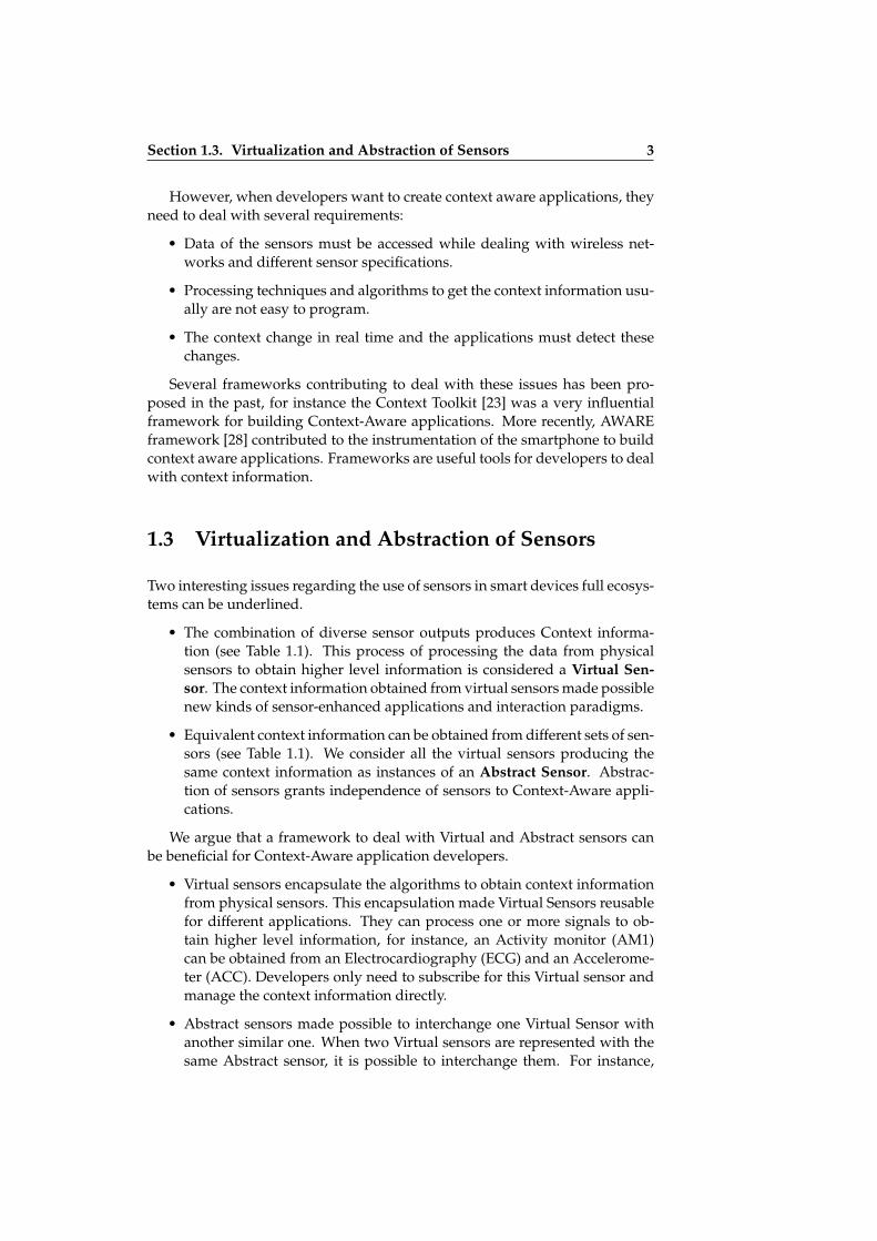
• The combination of diverse sensor outputs produces Context informa-tion (see Table 1.1). This process of processing the data from physicalsensors to obtain higher level information is considered a Virtual Sen-sor. The context information obtained from virtual sensors made possiblenew kinds of sensor-enhanced applications and interaction paradigms.
• Equivalent context information can be obtained from different sets of sen-sors (see Table 1.1). We consider all the virtual sensors producing thesame context information as instances of an Abstract Sensor. Abstrac-tion of sensors grants independence of sensors to Context-Aware appli-cations.
We argue that a framework to deal with Virtual and Abstract sensors canbe beneficial for Context-Aware application developers.
• Virtual sensors encapsulate the algorithms to obtain context informationfrom physical sensors. This encapsulation made Virtual Sensors reusablefor different applications. They can process one or more signals to ob-tain higher level information, for instance, an Activity monitor (AM1)can be obtained from an Electrocardiography (ECG) and an Accelerome-ter (ACC). Developers only need to subscribe for this Virtual sensor andmanage the context information directly.
• Abstract sensors made possible to interchange one Virtual Sensor withanother similar one. When two Virtual sensors are represented with thesame Abstract sensor, it is possible to interchange them. For instance,

ii
ii
ii
ii
4 Chapter 1. Introduction
Table 1.1: Examples of combination of physical sensors transformed into con-text information found in the literature
Author(s) Physical Sensors Context Information
Schmidt el al. [70] Temperature, Pressure, COGas Meter, Photodiode, Ac-celerometers, PIR and Mi-crophone
Mobile phone, User Activity
Haag et al. [43] EMG, Electro Dermal Ac-tivity sensor (EDA), SkinTemperature, Blood VolumePulse, ECG and Respiration
User Emotional State
Parkka et al. [57] Air Pressure, Microphone,Accelerometer, Humidity,Luminosity, ... (up to 22signals)
User Activity
Chon and Cha [17] GPS, Accelerometers, Com-pass, BT, WiFi and GSM
Smartphone, User Activity
Wiese et al. [79] Accelerometer, Light/Prox-imity, Capacitive and Multi-spectral
Smartphone, User Activity
Jang et al. [45] Skin Temperature, ECG,EDA and Photoplethysmog-raphy (PPG)
User emotional state
Reddy et al. [61] Accelerometer, GPS Transportation Modes
another Activity monitor (AM2) can use a the GPS and a Blood VolumePulse (BVP) sensor to get context information similar to AM1. Develop-ers do not need to know which Activity monitor are using (AM1 or AM2),they only need to subscribe to the Abstract Sensor for Activity monitorand delegate the instantiation to the framework (See Figure 1.1).
Two operations must be considered in the framework to provide advancedsupport for abstract and virtual sensors :
• Virtualization: It refers to the operation of obtaining higher level infor-mation processing one or more physical sensors.
• Abstraction: It refers to the operation of selecting a sensor from all thephysical and virtual sensors that produces equivalent output data.
In order to assist the development of Context-Aware applications regard-ing the Abstract and Virtual sensors, this thesis proposes the Igerri conceptualframework. Chapter 3 extends the ideas introduced in this section describingthe conceptual framework in depth.
In the following section, we contextualize the origin of Igerri in Egoki, aprevious research project of Egokituz laboratory.
ii
ii
ii
ii
Section 1.4. Egoki: Ubiquitous Computing in the Egokituz Laboratory 5
Figure 1.1: Example of Virtual and Abstract sensors.
1.4 Egoki: Ubiquitous Computing in the EgokituzLaboratory
Egoki is a user interface generator designed for Ubiquitous Systems. Its maingoal is to generate remote and accessible user interfaces for people with spe-cial needs. These user interfaces are adapted to the abilities of each user. Inthis way, users can operate services, such as information kiosks or vendingmachines, if they are supported by ubiquitous computing [6].
EGOKI allows ubiquitous services to be accessed by means of user-tailoredinterfaces, running on accessible mobile devices. The user-adapted interfacesare based on Web technologies (e.g. HTML, JavaScript and CSS) and are ac-cessible from the Web browser of the personal device [7]. Through the Webbrowser, all the personal devices with the proper assistive technologies (suchas screen-readers or screen magnifiers) can interact with the ubiquitous ser-vices. Therefore, not only a specific user interface was required for each ubiq-uitous service, but also accessibility must be ensured for each different userand device. To achieve this, Egoki uses a model-based paradigm [53, 54]. Tostore these models Egoki provides a Knowledge Base named EGONTO.
Unlike other approaches that use the original version of the user interfaceto generate and adapt one for the user [5], Egoki built the user interface fromthe following models:
• User model: it defines the abilities and preferences of the users in theUbiquitous Environment.
• Device model: it characterizes the device that renders the user interface.
• Adaptation model: it describes how and which information stored in themodels is used for the adaptation
• User interface model: it details the interaction elements with the servicesand the available multimedia resources. It uses a user interface Mod-

ii
ii
ii
ii
6 Chapter 1. Introduction
elling Language (UIML) format, a XML based user interface descriptionlanguage [36].
These models provide valuable information about the interaction contextwith the ubiquitous services: the appropriate multimedia resources, navigationschemes and adapted interaction techniques. All this information was used todeliver a suitable user interface to the users.
1.4.1 Requirements for Egoki Systems
In order to successfully generate the user interfaces, the Egoki System needs: Amiddleware for remote interfacing the Ubiquitous System, and the provisionof UIML files and multimedia resources for each Ubiquitous System.
For the first requirement, the URC/UCH middleware [82] was adopted [31].This middleware layer was implemented as an external server that adds func-tionality to the user interfaces generated by Egoki.
For the second requirement, we provided tools to assist Ubiquitous Servicesdesigners in the creation of the UIML code [55].
1.4.2 Evaluation of Generated User Interfaces for Egoki
Egoki was tested in different scenarios:
• Scenario 1 [54]: A remote controller for a television using a personal mo-bile computer in the context of the INREDIS project.
• Scenario 2 [6]: A metro ticket vending machine accessed by blind peoplewith their personal mobile computer (laptop).
• Scenario 3 [37]: Two Ubiquitous Services provided to people with cogni-tive impairments: A meal selection service in a canteen and an interactivebus timetable. They were evaluated with two user samples.
1. Cognitive impaired people interacting with a Tablet.
2. Blind people using their mobile computer or smartphone.
1.4.3 From Egoki to Igerri
The results of the evaluation of Egoki were successful but also raise a numberof questions to be addressed in future works:
(Q1) What are the limitations of Egoki when it comes to generating newinteraction modalities? Would it be possible to add gesture support in thecurrent Egoki System?

ii
ii
ii
ii
Section 1.4. Egoki: Ubiquitous Computing in the Egokituz Laboratory 7
We proved that Egoki can generate different output modalities such as: imageor audio at the same time. But for input modalities only the touchscreen andpoint and click paradigms were tested, for gesture recognition and techniquesalike, a detection mechanism for more input modalities is required.
(Q2) How good is an adapted user interface in a mobile context? Forinstance, a noisy environment affects the usability of a user interface basedin audio modality, how can Egoki deal with this?
The whole context of the interaction is not fully considered, just some param-eters for the user (interaction ability), and some device features (e.g. screensize or the availability of touch-screen). Thus, Egoki manages static contextinformation that does not change while the interaction takes place. In mobilecontexts, the environment usually is changing and this affects the quality ofthe interaction with the user interface. Moreover, sometimes the user can ex-perience temporal restrictions due to environmental noise (loss of hearing abil-ity) or be confused with a foreign language (degradation of his/her cognitiveskills). Egoki should be able to generate adaptive user interfaces to improvethe interaction in such dynamic contexts.
(Q3) Ubiquitous computing proposes changes in the interaction loop,with proactive applications able to modify their response without explic-itly asking the user. This would be translated to applications that are notcontrolled with a device. Would Egoki be able to manage this kind of in-teraction model?
This question is related to the previous one. As Egoki only generates the userinterface, it does not manage the interaction. This interaction is controlled bya Web browser and the Middleware layer. For instance, it is impossible forEgoki to notice if the user is walking or standing still, or if the device is in hisor her pocket or on a table. In both cases, the interaction should be different.To support this dynamic interaction model, mechanisms to react to the contextmust be injected in the Web based user interfaces.
(Q4) In the Ubiquitous Computing field, since the smartphone emergence,there has been a shift from remote applications to mobile native appli-cations (commonly called apps). Can Egoki be adapted to generate userinterfaces for these mobile apps?
Unfortunately, the design of the Egoki systems is tied to the existence ofremotely accessible ubiquitous services and it is not easy to use it for this pur-pose.
One of the foundations of Egoki is the generation of user interfaces for ubiq-uitous services. It was a legacy requirement of the INREDIS project, a researchwork started in 2007 and finished in 2010. In that period, context-aware com-puting was not so ‘smartphone centric’, due to this fact, the INREDIS projectwas focused on positional commerce: sporadic and opportunistic services tiedto the location of the user. Simultaneously, smartphone use and applicationstores started to grow and currently, these are widely used on a daily basis.People show great interest in standalone applications that run locally. These
ii
ii
ii
ii
8 Chapter 1. Introduction
applications take advantage of the context information inferred from the sen-sors in smartphones. Having said this, Egoki should try to generate user inter-faces for this kind of applications.
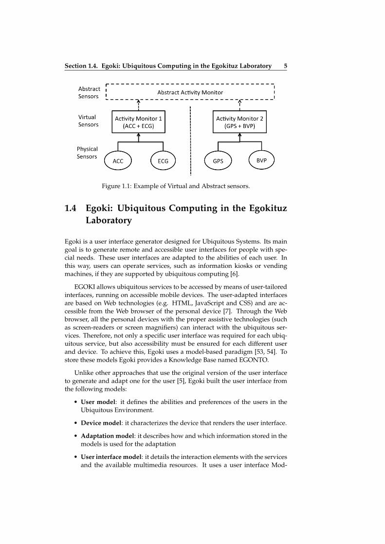
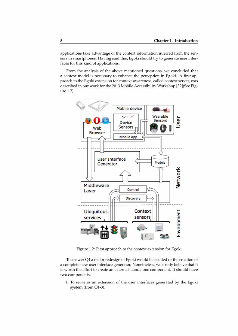
From the analysis of the above mentioned questions, we concluded thata context model is necessary to enhance the perception in Egoki. A first ap-proach to the Egoki extension for context-awareness, called context server, wasdescribed in our work for the 2013 Mobile Accessibility Workshop [32](See Fig-ure 1.2).
Figure 1.2: First approach to the context extension for Egoki
To answer Q4 a major redesign of Egoki would be needed or the creation ofa complete new user interface generator. Nonetheless, we firmly believe that itis worth the effort to create an external standalone component. It should havetwo components:
1. To serve as an extension of the user interfaces generated by the Egokisystem (from Q1-3).
ii
ii
ii
ii
Section 1.5. Research Questions and Hypothesis 9
2. To be able to manage native context-aware applications for the most pop-ular mobile platforms (from Q4).
In this way, Egoki would be able to support both Ubiquitous Services andstandalone apps.
From the previous analysis we deduce the following requirements for thecontext component:
• (R1) It has to manage data from sensors embedded in the environmentssmart devices, providing the abstraction and virtualization of sensors.
• (R2) It has to produce standalone applications with sensor driven inter-action techniques using web technologies, to be extensible to Egoki.
• (R3) It has to ease the development effort of developers, and be able towork as a rapid-prototyping framework.
This was the original foundation and motivation for the Igerri framework,the creation of both, an extension to Egoki, and, a sensor abstraction and virtu-alization framework for mobile context-aware applications. In addition to that,with Egoki being a starting point for this thesis work, another reason for Egokiand Igerri to be decoupled is that we wanted to work in a self-contained origi-nal piece of research. In the next section the research questions to be addressedwith Igerri will be presented.
1.5 Research Questions and Hypothesis
A good way to add perception is the adequate use of the embedded sensorsin the ubiquitous system. For that reason we propose a framework for sensorabstraction and virtualization in mobile context-aware computing.
Generally speaking, this means that we want to offer mechanisms to as-sist the generation of applications able to use different sensors simultaneously.This is not new in the context-aware literature. There are several frameworksfor the composition of context-aware applications, but they have different mo-tivations and goals. In our case, we want to contribute with one frameworkthat is designed to deal with different kinds of sensors at the same time in aneasy way, granting the usability of the created applications. Moreover, we wantto offer a tool to assist developers in the creation of applications with sensorshiding common issues of the sensor-driven applications.
Regarding the role of developers, usually they have to address the follow-ing challenges (Cn) to program a context-aware application [33] :
• (C1) Seamless Integration, to achieve seamless integration of the differentcomponents in ubiquitous environments we have to face the heterogene-ity challenge:
– (C1.1) Sensor heterogeneity. Due to the variety of devices and man-ufacturers, each sensor requires different low-level management in
ii
ii
ii
ii
10 Chapter 1. Introduction
order to obtain the information provided.
– (C1.2) Platform heterogeneity. Different mobile development platformsuse incompatible Software Development Kits (SDK) making impos-sible to share the same code for the same application running in dif-ferent target smartphones, even if they have the same set of sensors.
– (C1.3) Network heterogeneity. There are different networks availablein mobile devices. Each of them with different characteristics. Mostof the smartphones and tablets have Wifi and Bluetooth networkingproperties. In addition to this, there are no methods in the auto-matic discovery mechanisms to identify the properties of connecteddevices and to access the sensor information.
• (C2) Context recognition. Developers devote considerable efforts to recog-nizing activities happening in the mobile phone context. For each activitythe available data has to be analysed and models to match these activitieshave to be designed and trained.
• (C3) Performance. Mobile devices usually make a trade-off between powerconsumption rate and processor activity. The proliferation of indepen-dent sensor readings and heavy processing algorithms run by differentapplications critically affect the performance of the battery.
It would be really helpful if the sensor abstraction and virtualization frame-work could provide mechanisms to deal with these issues. The design andimplementation of the framework will take into account theses issues.
Aside from the development aspect, we want to focus on testing whetherthe usability of the created applications is appropriate or if they contain flaws.We consider users as the best test-bed for Mobile Context-Aware applications.If users feel comfortable with the applications the sensor integration shouldbe well suited and the performance flawless. For this reason, the followingresearch questions are proposed:
Research Question 1. Can Igerri produce functional and usable ap-plications with its implementation of the mobile Context-Aware frame-work ?
Research Question 2. Are the users able to control sensor enhancedapplications following the Igerri approach ?
Research Question 3. Do the users perceive sensor enhanced Igerriapplications as appealing, engaging and/or of added value ?
On the whole, these questions lead to the following hypothesis: The abstrac-tion and virtualization of sensors as presented in Igerri are valid techniques to developusable Context-Aware applications.
Igerri is designed to provide clear insight into the above mentioned re-search questions and hypothesis.

ii
ii
ii
ii
Section 1.6. Research Process 11
1.6 Research Process
To start, the revision of the work carried out with Egoki [6, 36, 37, 54] pointedout the need of a context-aware module and inspired this work.
Literature in context-aware computing was reviewed and adequate researchquestions were set after deciding to focus on the abstraction and virtualizationof sensors.
Next the interest in the research addressed with this thesis was contrastedwith three position papers for different research communities: Mobile Acces-sibility [32], Pervasive Computing [33] and Human Computer Interaction [34].The first approach to the proposed system is depicted in Figure 1.3).
Figure 1.3: Summary of the elements in the Abstraction and VirtualizationFramework
ii
ii
ii
ii
12 Chapter 1. Introduction
After collecting all the feedback, a conceptual framework named Igerri wasestablished. Later Igerri was instantiated with an implementation divided intwo components: MobileBIT, which was devoted to sensor abstraction and vir-tualization and PervasiveBIT, which is dedicated to conceal networking andsensor discovery issues.
When the implementation was ready, representative applications were de-signed and implemented. The usability of the applications were tested with atotal of 29 users. The conclusions for this work were obtained using the resultsfrom the usability evaluation.
1.7 Conclusion
This chapter sets the basis of the research that has been conducted in the topicof sensor abstraction and virtualization. In the next Chapter, the state of theart is described and related work is summarized. In Chapter 3, the concep-tual framework with all the required concepts to resolve these problems is ex-plained. In Chapter 4, a reference implementation of the abstraction and vir-tualization of sensors is depicted. In Chapter 5, the evaluation of the previousimplementation is described. Finally Chapter 6, conclude this thesis work anddescribes the validation of the hypothesis and the contributions to the mobilecontext-aware area.

ii
ii
ii
ii
Chapter 2
Background and RelatedWork
This chapter provides background in the area of the topics covered by thisthesis. Previous and significant works are introduced as part of the stateof the art and related work is presented.
2.1 Introduction
This thesis is located in the field of Ubiquitous Computing, and more preciselywithin the topic of Context-Awareness. Its objective is to contribute with aframework for sensor abstraction and virtualization for mobile context-awarecomputing. Thus we focus on how to discover and extract context informationusing the data collected by sensors.
A general overview of the Ubiquitous Computing and Context Awarenesswas briefly introduced in the first chapter. Nevertheless it is worth mention-ing some works in this area in order to better understand the research workproposed in this thesis.
2.2 Ubiquitous Computing
Ubiquitous computing is a multidisciplinary field of research, born out of theevolution of distributed computing and mobile computing [66]. Other areassuch as human-computer interaction, expert systems and software agents arealso influential in ubiquitous computing.
The tasks forming the challenges to be overcome for ubiquitous computingto become a reality were an important research driver for the ubiquitous com-puting field. From year 2000 to 2003, coincident with the tenth anniversary of
13

ii
ii
ii
ii
14 Chapter 2. Background and Related Work
the field, several seminal papers [9, 22, 65, 66] established the research agendafor ubiquitous computing. Challenges such as: Effective use of smart spaces,Scalability, Heterogeneity, Integration, Invisibility, Perception, Smartness, etc.were described.
These works agreed on identifying the discovery and management of con-text information as being one of the main challenges. This process involves theterm perception and it is commonly related to Context-Awareness.
2.3 Perception
From a psychological perspective, human perception is the process of noticingand understanding the stimulus energies (e.g. light or sound) from the envi-ronment. Perception is closely related with sensation, which is the process bywhich these stimulus energies are received [81]. The perception of the physicalworld is carried out by means of sensory receptors. They are able to detect andtransmit to the brain information originating from a stimulus. In other words,humans can see, hear, taste and smell thanks to the sensory receptors, and per-ception takes place when those stimuli are organized and interpreted by thebrain.
An interesting approach to explain how perception works is the perceptualprocess described by Goldstein [42]. This process starts with a stimulus in theenvironment of the person and ends with a behavioural response in the subject.This response involves perceiving, recognizing and taking actions. Goldsteinidentifies perception and recognition as part of a mental process assisted bypreviously existing knowledge.
This perceptual process can be imitated by computers systems. The sensorsare connected to devices with computational power in order to analyse thedata collected and to transform them into context-information. Research areassuch as Artificial Intelligence and Robotics have their own uses of the percep-tion concept. However, for this thesis we focus on the Ubiquitous Computingbackground. Perception has been described for this area in several seminalworks as it is a key concept for the ubiquitous computing.
Schmidt identified perception as a part of his influential work about im-plicit human computer interaction [68]. When a person interacts with a com-puter an explicit interaction is expected. The computer expects to receive com-mands to be operated in a certain way. Implicit interaction is the additionalinformation that a computer can understand which is not primarily aimed forinteraction. There are two main concepts for Implicit interaction, namely per-ception and interpretation. Schmidt’s vision foresees devices with the abilityto see, hear and feel. "Based on their perception, these devices will be able toact and react according to the situational context in which they are used".
The work of Saha and Mukherjee [65] identified perception as being asmuch of a challenge for the field of pervasive computing as other challenges

ii
ii
ii
ii
Section 2.4. Context-Aware Systems 15
such as, Scalability, Heterogeneity or Invisibility. For these authors, perceptionis equivalent to Context-Awareness. They identify issues derived from imple-menting perception: location monitoring, uncertainty modelling, real-time in-formation processing and merging data from multiple, and possibly disagree-ing, sensors. The perception challenge is complemented with another conceptcalled Smartness or Context Management, which is defined as the means ofusing the perception effectively.
Cook et al. [18] described perception as part of the sensing process for theAmbient Intelligence (AmI). A variety of sensors can be used to achieve thePerception. Software algorithms perceive the environment using these sensors.After the sensing stage, the reasoning process is carried out.
Coutaz et al. [21] describe perception as part of the abstraction for a general-purpose infrastructure for Context-Aware computing. They locate the percep-tion layer between the sensing layer and the situation and context identificationlayer.
Finally, Aarts and Wichert [3], describe a 3-step process to obtain context-information for perception of the situation in AmI. For them, perception isagain related to the context-awareness. The first step, called sensing, relieson wireless sensor networks to gather information. The second step entails,among others, the processing of information, data combination, classificationor sensor fusion. Finally, the third step is the interpretation of the contextualinformation to obtain information on a higher semantic level.
We have found different definitions for the concept of perception in theabove mentioned works. Some of them use it as a synonym of Context-Aware-ness, but in most cases they refer to the process of acquiring data from sensorsand to transform it into high level contextual information. Usually, perceptionis the previous stage to the interpretation, reasoning or similar processes whichtake place after the perception of the context-information.
Igerri aims to provide a comprehensive vision of perception and to supportthe process of transforming sensor information into usable context-information.With the proposed framework, the ubiquitous computing system devices havethe capability of using sensors to transform the stimuli of physical environ-ment including the users and objects in that location into high level context-information. This is possible, firstly through virtualizing sensors able to per-ceive context-information, and secondly by achieving sensor abstraction.
2.4 Context-Aware Systems
The concept of perception is part of the Context-Awareness property of Ubiqui-tous Computing. Usually systems that focus on Context Awareness are calledContext Aware Systems.
Probably, the first work relating context with ubiquitous computing wasthe project Active Badge [76]. A project to locate people in office environments

ii
ii
ii
ii
16 Chapter 2. Background and Related Work
using wearable badges as beacons. Nevertheless it was only after the workof Shcilit et al. [67] when Context Aware Computing was defined, inspiredthe Ubiquitous Computing. The authors introduced a handheld wireless de-vice called PARCTAB able to react to changes in the environment. Four cat-egories for context applications were defined based on whether the task wasobtained information or activating a command, and on whether the commandwas effected manually or automatically. The first context aware systems werestrongly linked to location information.
Many authors tried to contribute with useful Context definitions for Context-Aware Systems [14, 64, 67]. Anyway, this thesis assumes a popular definitionof Context stated by Dey in 2001 [24]:
“ Context is any information that can be used to characterisethe situation of an entity. An entity is a person, place, or objectthat is considered relevant to the interaction between a user anda application, including the user and application themselves”. —Anind K. Dey (2001).
The same author defined a Context-Aware System as follows,
“ A system is context-aware if it uses context to provide rele-vant information and or services to the user, where the relevancydepends on the user’s task”. —Anind K. Dey (2001).
Context-Aware systems are usually composed of a set of networked deviceswhich share context-information acquired from the embedded sensors. Then,Context-Aware applications require access to that context-information in or-der to adapt the interaction. All the entities involved in the interaction can beidentified by the developer when it is designing the application. These enti-ties are then characterized by the context-information available in the context-aware systems. For this purpose, sensors are a valuable source of context-information.
2.5 Mobile Phones in Context-Aware Computing
Mobile Phones have been used for Context Aware Computing since its ori-gins. They can be seen as the instantiation of the original devices envisionedby Weiser in the foundational works of Ubiquitous Computing [77]. These de-vices are very useful because they are carried by potential users of ContextAware environments and they have embedded diverse sensors that enable theacquisition of context. One of the advantages of having multiple sensors in thesame device with different functionalities is the possibility of combining sev-eral sources of data to obtain higher-level context information. A plethora ofworks have been proposed following this approach. Over time, the complexityand number of sensors included in mobile devices has increased.
One of the first works presenting this approach was the TEA project (Tec-nology for Enabled Awareness) by Schmidt et al. [70]. The TEA project pro-
ii
ii
ii
ii
Section 2.5. Mobile Phones in Context-Aware Computing 17
posed a self-contained multi-sensor device connected to a Nokia 6110 mobilephone using a serial interface. This work describes the fusion of eight sensors(temperature, pressure, CO gas meters, a photodiode, two accelerometers, apassive IR, and a microphone) to recognize different means of transport. Ad-ditionally, it detects whether the mobile phone is in the hand, in the suitcase oron the table, among other contexts. With this context information, the mobilephone swaps between different preprogrammed profiles affecting the notifica-tion of calls: the volume of audio alarms, vibration, or the use of silent mode.
Korpipää et. al [49] published a very interesting work regarding the use ofontologies. They created an ontology for managing context information in mo-bile devices and introduced a framework for context-aware application devel-opment for Nokia series 60 smartphones (Symbian platform) [48]. This systemuses a central node to store the context information following the blackboardmodel proposed by Winograad [80]. Context information related to Environ-ment, Device placement and user activity was obtained by means of accelerom-eters, audio, light, temperature and touch sensors.
Since the arrival in 2007 of the iPhone followed by Android Smartphonesin 2008, the area of Mobile Context Aware computing started to use these de-vices intensively. Modern Smartphones contributed to the general use of theGPS to provide outdoor location and inertial sensors for movement acquisi-tion. For instance, LifeMap [17] is an application able to recognize the contextwithin which a smartphone is being used by means of regular sensors (GPS,accelerometers, compass, etc.). It can detect whether the user is walking, run-ning, etc.
Other approaches propose to add new advanced sensors to obtain context-information. As an example Phoneprioception [79] studies the ability of smart-phones to identify where they are (bag/pocket/hand/etc.). To do this, it com-bines four sensors: accelerometer, light/proximity, capacitive and multispec-tral. The last two sensors are prototypes incorporated specifically for this pur-pose in the smartphone.
2.5.1 Wearable Devices and Physiological Signals
In recent years, the sensing capabilities of modern smartphones have been ex-tended with wireless wearable devices. Due to advances in body area net-works, miniaturization and the affordability of advanced sensors for physio-logical computing, these devices now provide opportunities to discover newcontext information regarding physiological signals such as:
• Heart beats and heart rate can be acquired by means of diverse tech-niques such as: Electrocardiography (ECG) or Photoplethysmography(PPG).
• Muscles activity can be perceived by means of Electromyography (EMG)and Acceleremoters (or Inertial Measurements Units) attached to bodylimbs.

ii
ii
ii
ii
18 Chapter 2. Background and Related Work
• Arousal level is obtained by means of Electrodermal Activity (EDA), Gal-vanic Skin Response (GSR) or Skin Temperature sensors (ST).
• Other physiological signals such as Respiration rate (RR), can also be de-tected by means of diverse physiological sensors.
An interesting example of these devices is BITalino, a wireless sensor plat-form highly adaptable for wearable computing [72]. BITalino includes EMG,ECG, EDA, Accelerometry and Luminosity sensors in a single board. This PhDused BITalino as sensor source device in the evaluation chapter.
Background information about the user can be obtained by combining in-formation from wearable sensors [56]. They enable the detection of physio-logical signals (or biosignals), which leads to the extraction of information onactions performed by the person wearing them, as shown in the survey pub-lished by Avci et al. [8]. There are plenty of applications for these externalsensors, for instance Costa and Duarte [19] aim to use surface EMG sensors toimprove accessibility for blind people with mobile devices.
A different approach is to use physiological wireless sensors to provide Mo-bile E-Health services and applications. For instance, the work of Villareal etal. [75] propose an architecture for the medical control of chronic diseases andpresents a case study for patients with diabetes. Similarly, mHealthDroid [11]follows a smartphone centered approach and provides a framework to createsmartphone applications for the medical domain.
Additionally, user’s emotions can also be detected. For instance, the workby Haag et al. [43] identified the emotional states of a user in terms of valenceand arousal, by combining a set of biosignals: EMG, EDA, ST, Blood VolumePulse sensors (BVP), ECG and RR. Similarly, the work of Jang et al. [45] clas-sified three negative emotions (fear, surprise and stress) from four biosignals:ST, ECG, EDA and PPG.
2.5.2 Sensors in Context-Aware Computing
Sensors are one of the enabling elements to generate context information, andconsequently to support Context-Aware information. We focus on sensors thatobtain information from physical stimuli. We call them Physical Sensors. Adefinition of Physical Sensors can be found at Kalantar et al. [46],
“ A sensor is a device which responds to stimuli (or an inputquality) by generating processable outputs. These outputs are func-tionally related to the input stimuli which are generally referred toas measurands”. —Sensors: An Introductory Course (2013) [46].
Beyond this definition we can also obtain a first approach of how a sensorworks,
“ A sensor is commonly made of two major components: a sen-sitive element and a transducer. The sensitive element has the capa-bility to interact with a target measurand and cause a change in the
ii
ii
ii
ii
Section 2.5. Mobile Phones in Context-Aware Computing 19
operation of the transducer. Affected by this change, the transducerproduces a signal, which is translated into readable information bya data acquisition system... The processing information is then sentto a processing system, where it is processed into meaningful infor-mation”. —Sensors: An Introductory Course (2013) [46].
2.5.3 Sensor Categorization Regarding Context Entities
Sensors can be classified following their relationship with the entities in theinteraction context. In this way, it is possible to categorize which sensors areuseful to gather context-information about the: 1) environment, 2) objects and3) people, involved in the context-aware application. With this information,the context-aware applications can adapt the interaction with the user.
• Environment. A number of environmental variables can be gathered us-ing sensors. E.g. the level of light in a room can be measured to adaptthe brightness of a smartphone apps. The noise level can also be mea-sured using a microphone and therefore applications can use this context-information to change the modality of an audio user interface to a moresuitable one.
• Object. Several context-aware applications require information aboutcertain objects in order to work properly. These objects usually includeembedded sensors to gather this information. The most common ob-ject considered in the context-aware domain is the electronic device usedto access the context-aware application, namely the Smartphone/Tablet.E.g. By means of inclinometer sensors embedded in a smartphone, it ispossible to know what it is the position of the display and switch thevisualization of apps between landscape or portrait layouts.
• Person. Context-aware applications can require information about peo-ple involved in the interaction with the application. The main personconsidered for this purpose is the user. It is possible to gather informa-tion about the user activity, emotional state, and the position. For thesepurposes, both the smartphone and wearable devices are used to obtaindata. Context-aware applications can use activity information to improvethe interaction with the user, e.g. avoid displaying certain notificationmessages if the user is running.
More examples are depicted in table 2.1,
In Igerri we consider all sensors characterize entities. In some cases, thesame sensor type can be used to characterize different entities in different ap-plications. This is the case of the inertial sensors embedded in smartphones.They can be used to obtain context information about both the position of thesmartphone (in the hand, in the pocket) and the user activity (walking, run-ning, resting). Therefore the framework must be flexible enough to avoid al-ways matching a specific sensor with the same entity. Some sensors using elec-trodes depend on the location of the electrode to obtain context-information

ii
ii
ii
ii
20 Chapter 2. Background and Related Work
Table 2.1: Different physical stimulus measured with sensors
Characterized Entity Measurand Sensor Name
Environment Temperature ThermometerHumidity Humidity sensorPressure Barometer
Lux Luminosity sensor
Object Movement AccelerometerGyroscope
Magnetic fields Magnetometer
Person Heart Rate ElectrocardyographMuscle Activation Electromyograph
Arousal Electrodermal Activity SensorMovement Accelerometer
Gyroscope
about a specific limb. The developers of context-aware applications have tospecify how to set up the devices and sensors before starting the context-awareapplication.
2.5.4 Sensor Categorization Regarding the Communication In-terface
When it comes to communication of the sensors with the system, we can finddifferent classes:
• Simple sensors. Sensors that are sold separately and need to be con-nected to a microcontroller. Usually these sensors are wired and need tobe physically connected to an input pin or a bus of the microcontroller.So far, we can identify two kind of connections:
– Pin based: They are wired to analog or digital input pins. For theformer they have to be connected to an Analog to Digital Conversor(ADC) to obtain binary values. For the latter, they directly producebinary values.
– Bus based: They use a specific communication bus. Some sensorsattached to a basic microcontroller still need to be connected to amore powerful microcontroller to manipulate the data. This kind ofsensor uses communication protocols and buses, such as the serialport (RS-232), I2C, SPI, etc.
• Sensor devices They are also called sensor platforms. They have all the
ii
ii
ii
ii
Section 2.5. Mobile Phones in Context-Aware Computing 21
components that enable the the sensors to be used. We can distinguishbetween two types of sensor devices:
– Network based: Some sensors require a networking interface. Forinstance, Bluetooth or WiFi.
– API based: Other sensors are embedded in the device where thecontext is used. Usually, these sensors are accessible through thesystems API’s.
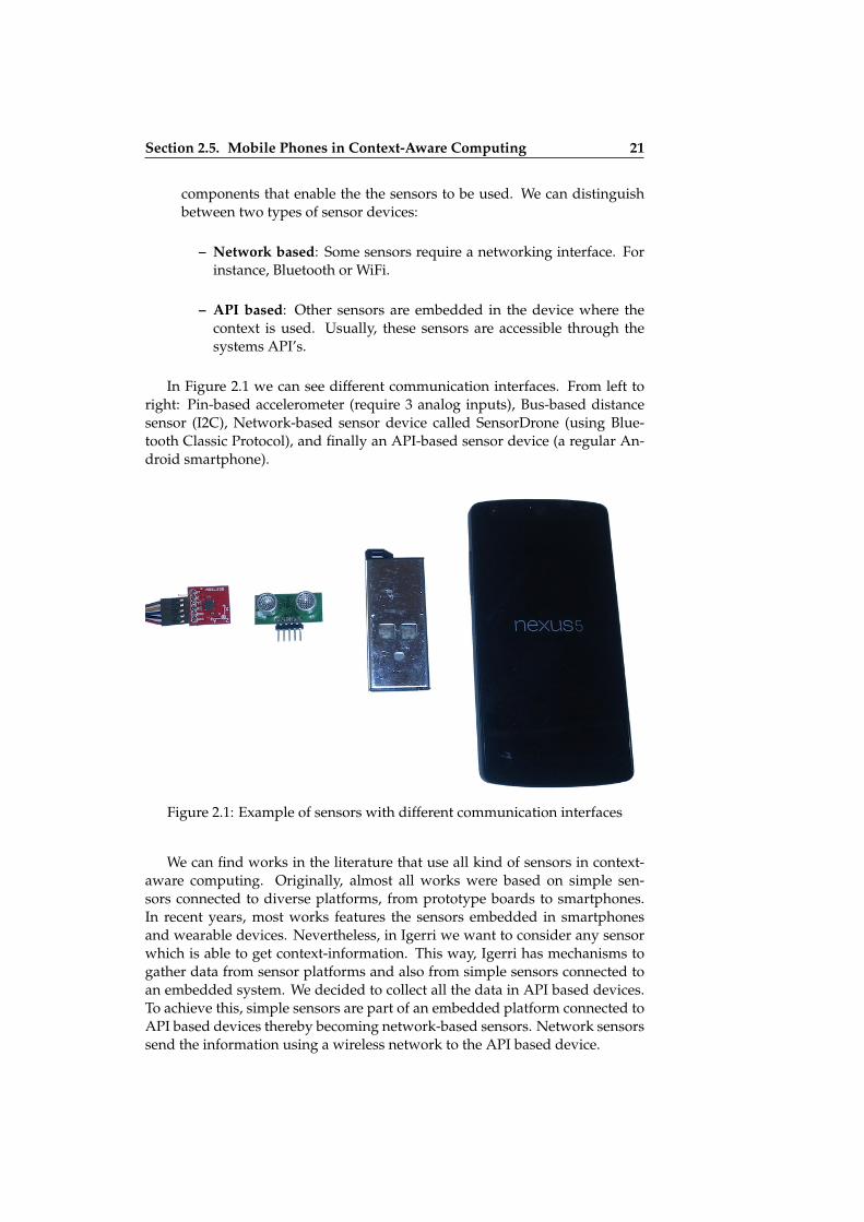
In Figure 2.1 we can see different communication interfaces. From left toright: Pin-based accelerometer (require 3 analog inputs), Bus-based distancesensor (I2C), Network-based sensor device called SensorDrone (using Blue-tooth Classic Protocol), and finally an API-based sensor device (a regular An-droid smartphone).
Figure 2.1: Example of sensors with different communication interfaces
We can find works in the literature that use all kind of sensors in context-aware computing. Originally, almost all works were based on simple sen-sors connected to diverse platforms, from prototype boards to smartphones.In recent years, most works features the sensors embedded in smartphonesand wearable devices. Nevertheless, in Igerri we want to consider any sensorwhich is able to get context-information. This way, Igerri has mechanisms togather data from sensor platforms and also from simple sensors connected toan embedded system. We decided to collect all the data in API based devices.To achieve this, simple sensors are part of an embedded platform connected toAPI based devices thereby becoming network-based sensors. Network sensorssend the information using a wireless network to the API based device.

ii
ii
ii
ii
22 Chapter 2. Background and Related Work
2.6 Related Work
2.6.1 Context Widgets
Dey’s Conceptual Framework [25] and its implementation, the Context Toolkit,is one of the seminal works in the topic of Context Aware Frameworks becauseof the identified problems and provided solutions. This work identified andestablished the features necessary for architectural support to Context-Awareapplications: context specification, separation of concerns, context interpreta-tion, transparent distributed communications, constant availability of contextacquisition, context storage and resource discovery. One of the most interestingcontributions of the conceptual framework is the architectural building blocks.A reusable set of components which are implemented in the Context Toolkitwere introduced:
• Widgets collect information about the environment through the use ofsensors.
• Interpreter transforms low level context information into high level.
• Aggregators provide applications with related context about an entity.
• Discoverer locates context components that are of interest to applica-tions.
• Services are responsible for changing the environment using actuators.
The Functional Blocks presented in MobileBIT which are an implementa-tion of the Igerri framework, are influenced by the Building Blocks and Widgetapproach. While Dey’s work provides a full structural and architectural sup-port for Context Aware applications, Igerri specialised in the Sensor Abstrac-tion and Virtualization.
2.6.2 Computing in Context
Schmidt’s Ubiquitous Computing, Computing in Context [69], provides a percep-tion architecture for Context-Aware systems. This layered architecture hasthree levels:
• Sensor Layer composed of both physical and logical sensors. While phys-ical sensors are similar to the ones used for this PhD, logical sensors arecomponents that provide information about the real world but do nottake it from the environment (e.g. a server offering the current exchangerate).
• Cue Layer provides an abstraction of the sensor layer. A cue is describedas a function with values of single sensors up to a certain time as theinput, and a symbolic output. Each sensor has its own cues and can havemore than one cue. The cues implement perception methods, a kind of
ii
ii
ii
ii
Section 2.6. Related Work 23
processing methods based, among others, on statistical functions, timedomain analysis and rule based systems.
• Context Layer is composed of conditions with which to evaluate the cuelayer. It contains relevant context descriptions for a particular applica-tion. This layer can support learning capabilities to change contexts overtime based on adaptive algorithms.
Igerri layered framework is comparable to the perception architecture. First-ly, the sensor layer is equivalent to Igerri’s physical sensor layer. Logical sen-sors are not considered in Igerri, but they can be implemented using the SourceBlocks of MobileBIT. As far as the Cue and Context Layer are concerned, theseare comparable with Igerri’s virtual sensor layer and context service layer. Butthey are more constrained due to the fact that Igerri’s abstract sensor layerenables the interchange of similar virtual sensors which contains the same in-formation.
2.6.3 BeTelGeuse
According to Kukkonen et al. [50]: "BeTelGeuse is an extensible data collec-tion platform for mobile devices which automatically infers higher-level con-text from sensor data.". BeTelGeuse is designed to be multiplatform, extensiblefor new kinds of sensing devices, data accessible, high-level context extractionand takes into account the user experience. It uses a blackboard model to accessthe context information [80]. BeTelGeuse considers four types of sensors, exter-nal Bluetooth sensors, integrated phone sensors, software sensors and internetsensors. These sensors can be extended using Context Parsers, abstraction ofsensors that read and parse data, and write it on the blackboard. This platformwas implemented for Nokia S60 devices.
Regarding the abstraction of sensors, all the processing is managed by theContext Parsers, while Igerri divides it in different layers. The most interestingfeature is the extensibility of the framework. The implementation of Igerri al-lows the addition of new Functional Blocks with different purposes in a similarway.
2.6.4 AWARE Framework for Mobile Instrumentation
Ferreira proposed a mobile instrumentation toolkit called AWARE [28] in or-der to study the human behaviour, routines and context. AWARE is aimed toassist researchers, developers and users. It is focused in four activities: sensingcontext, storing context, sharing context and using context. Aware has an eightlayer theoretical architecture from which two layers are relevant to this thesis:the sensing layer and the context layer.
The sensing contains three types of sensors:

ii
ii
ii
ii
24 Chapter 2. Background and Related Work
• hardware-based: They can be embedded in the mobile or externally con-nected.
• software-based: They include network data sensors, algorithm-based sen-sors, and a derivative of sensor-fusion
• human-based: They collect data directly asking the user
The Context layer, abstracts the data and produces context. This layer con-tains reusable add-ons called Context Sensors that use techniques such as datamining or machine learning to obtain higher-level contexts. Context sensorswork unattended and are not operated by users. AWARE framework is com-posed of a client application developed for Android and a Server to store andreuse context data with other external sensors and applications, installable in aweb server.
AWARE supports more types of sensors apart from Igerri physical sensorsand the layered framework takes several concerns into account. Nevertheless,Igerri has implicit support for substitution sensors with the abstraction of sen-sors.
2.6.5 A Pluggable Middleware Architecture
The work of Paspallis et al. [58] presents a pluggable and modular middlewarearchitecture for developing context-aware mobile applications. It uses compo-nents with the roles of context providers (abstractions for sensors) and context-consumers (applications). The context plugins are designed to be reusable andthe context management is dynamically composed by the middleware layer.A very interesting property is that the middleware is able to activate or deac-tivate context plug-ins as needed. When an application is started it registersfor certain context types and then the middleware checks if there are availableplugins to obtain this context and activate them on demand.
Despite not being focused on the sensor abstraction, this work shares simi-lar properties to the MobileBIT implementation. Using a DPL generated withPervasiveBIT it is possible to obtain similar behaviour in the applications. None-theless, our conceptual framework is designed to separate concerns more ac-curately, due to the Virtual Sensor and Abstract sensor layer.
2.6.6 mHealthDroid
mHealthDroid [11] is the implementation of a mobile health framework in-tended for agile development of applications. Despite being restricted to thedomain of mobile health, it was considered for the related work revision dueto the capabilities of obtaining and visualizing context information. The ar-chitecture of the framework is composed of several modules called managers.Communication manager and data processing managers are the most relevantto this PhD:

ii
ii
ii
ii
Section 2.7. Conclusion 25
• The communication manager abstracts the applications from the under-lying health technologies. This level is composed of adapters, standalonemodules intended to manage the connection with biomedical devices anddeals with data acquisition.
• The data processing Manager provides signal processing, data miningand machine learning techniques. These tasks are split into four indepen-dent modules: preprocesing, segmentation, feature extraction and classi-fication.
The MobileBIT’s source blocks share a common goal with the communica-tion managers. Similarly the MobileBIT’s normal blocks are used for similartasks to those of the data processing manager.
2.6.7 Ghiani et. al’s Context Server
In Ghiani et al. work [39] a context-dependent multimodal augmentation en-gine is presented for web applications. This system is able to react to the con-text and adapt in real time to the modality of the visited web. The contextacquisition is done by means of a Context Server and Context delegates:
• Context Delegates can be deployed in smartphones or in other devicesin the environments and communicates the sensor data to the contextserver.
• Context sever is subscribed to the delegates and processes the data toobtain the context information. Once a change in the context informationis detected the modality of the user interface can change.
This work is the perfect example of what can be achieved with Egoki whenit is combined with Igerri. The main difference is the lack of mechanisms withwhich to transform sensor data in the smartphone. Following our sensor ab-straction approach it would not be necessary to send sensor data to the serverin order to discover changes in the context.
2.7 Conclusion
In this chapter the state of the art in sensing technologies, context-awarenessand mobile context-aware computing provide the background for this research.The work developed in this thesis was compared with similar research and thedifferences and advantages of Igerri and its implementation have been pointedout.

ii
ii
ii
ii

ii
ii
ii
ii
Chapter 3
Igerri Conceptual framework
In this chapter, a conceptual framework for sensor abstraction and vir-tualization is proposed. For that purpose, this chapter outlines the con-cepts necessary to understand the approach and the definition of the sys-tem model under consideration. In addition, the formal model of the sys-tem is described to define the relationship of the sensors with the context-information in an abstract way.
3.1 Introduction
Virtual machines have been used in diverse fields, such as Operating Systemsand Computer Architecture, to structure and model complex computers. Themain idea is to create a hierarchy of machines, each one able to run its spe-cific set of commands. These machines are virtual because they cannot runtheir language by themselves. Thus, each machine rewrites or translates itsown commands into the language of the next lower machine, maybe addingsome required contextual information. The task comes down the hierarchyuntil reaching the lowest layer machine, the hardware, the only machine ableto run its own language. Among the many advantages of this structure, twostand out:
• Abstraction: more powerful and abstract languages can be designed. Theonly condition is to be able to translate them into a lower lever languagerun by the next virtual machine.
• Independence of each machine from the lower layer virtual machines. Avirtual machine can be replaced only by rewriting the interfacing pro-grams that translate from a machine to the next one.
Since our objective is to design a framework that provides context infor-mation to context-aware applications in a simple way that ensures indepen-dence from the hardware and extensible abstraction, we proposed a multilayer
27
ii
ii
ii
ii
28 Chapter 3. Igerri Conceptual framework
model inspired in the Virtual Machines model for computer architecture. Thedefinition of the conceptual model (independent of the implementation) facili-tates communication and mutual understanding among the development teammembers, helps the implementation of coherent and compatible systems andimproves the modularity and reusability of the interaction software developed.In the next sections we will define the elements that compose the model, theabstraction layers, and the procedures to translate one layer to the next one.With this model we want to achieve independence of the application from thespecific hardware sensors required for context awareness, and abstraction toprovide the applications with more expressive context information.
3.2 Definitions
3.2.1 Sensors
Physical Sensor
A physical sensor is a device that returns a numeric value within a range, basedon the state of a physical parameter.
Physical_Sensor (Settings, Output, Function)
where:
• Settings are all values and procedures required for the sensor to return avalue. They may include activation parameters, programming, protocols,etc.
• Output is the current value of the sensor. To facilitate its interpretation, itcan include extended information such as range, resolution, etc.
• Function is the semantic interpretation given to the numerical output. Todo it, a lexicon containing the properties of all the functions available isrequired. This semantic interpretation is required in order to be able toprogress in higher abstraction. Higher layers ignore technical details andcharacteristics of the sensors and concentrate in their purpose. They needenriched semantics in order to be able to do suitable matches.
Properties:
• Physical sensors are pieces of hardware and software able to produceoutputs related to the status of specific physical parameters.
Virtual Sensor
A virtual sensor is an element that transforms data from one or more physicalsensors into another set of numerical data.

ii
ii
ii
ii
Section 3.2. Definitions 29
Virtual_Sensor (Settings, Input, Output, Function)
where:
• Input is the set of physical or virtual sensors that feed data to the virtualsensor.
• Settings, Output and Function are defined as for the physical sensor.
Properties:
• Virtual sensors allow the combination of information from different sen-sors.
• They also allow processing the output data (e.g. applying translations ordata-mining algorithms).
Abstract Sensor
An Abstract Sensor is a representation of all sensors that have the same func-tion. Abstract sensors ignore settings, physical parameters and several othercharacteristics that distinguish the sensors that produce a compatible outputwhenever measuring the same physical parameter.
Abstract_Sensor (Output, Function)
where:
• Output and function are defined as for physical and virtual sensors.
Properties:
• Abstract sensors are independent of the hardware.
• They allow the designer to use a sensor without worrying about theirspecific characteristics.
3.2.2 Hierarchy of Layers
The proposed sensor layers are structured in the following hierarchy (see Fig-ure 3.1):
Virtual Layer of Context Service (VLCS)
The Context Service is a layer that takes data from abstract sensors and pro-duces predefined context information within a specified range described in arepository named “Parameters”. It allows developers to use previously speci-fied specific context properties without directly processing data of sensors. It

ii
ii
ii
ii
30 Chapter 3. Igerri Conceptual framework
Figure 3.1: Sensor layer hierarchy
also allows applications to easily share context information. In this way ap-plications can be simultaneously context consumer and provider. It requiresinformation such as the names of the diverse context sources (Function) andhow the abstracts sensors are matched to virtual sensors. This information iscontained in the Parameters repository.
Virtual Layer of Abstract Sensors (VLAS)
The designers of the sensor structure that supports the context service can onlyaccess a virtual layer that contains abstract sensors, to avoid programming thespecific sensors available in a device. The context request made from the Con-text Service layer always refers to abstract sensors, which are described in theParameters repository.
Virtual Layer of Virtual Sensors (VLVS)
Abstract sensors are matched with virtual sensors that collect and process in-formation from physical sensors and other virtual sensors using the descrip-tions contained in the Parameters repository.
Physical Layer of Physical Sensors (PLPS)
This contains the actual sensors installed on a particular device and its environ-ment. They are able to collect contextual information. A physical sensor maybe composed of a transducer that converts the physical parameter to an electri-cal signal, a conditioner which adjusts the values of the electrical signal to beprocessed, and an analog/digital converter that samples the electrical signaland assigns a numeric value within a range to each sample.

ii
ii
ii
ii
Section 3.3. Transformations 31
3.3 Transformations
An important characteristic of the virtual multilayer structure is that interac-tions are only allowed between adjacent layers and through well defined in-terfaces. Therefore, since interactions between non-adjacent layers are not al-lowed,void transformations are required in order to communicate elements lo-cated in non-adjacent layers. In our framework, the interface between virtuallayers is defined in terms of transformations. An element of a layer is the resultof applying a transformation to another element in an adjacent layer.
Element (parameters) ← Transformation_from_Layer_to_layer(Transformation_Parameters) [Element(parameters)]
where Transformation_Parameters are the data structures required for thetransformation. The syntax A ← B[C] indicates that the element A is obtainedapplying the transformation B to the list of elements C. Two types of trans-formations are defined: translations and requests. Translations are transforma-tions that allow progress to be made upwards in the abstraction scheme. Whenapplying a translation to an element a more abstract element is obtained.
Element(parameters) ← Translation_from_Layer_to_Layer(Translation_Parameters) [Element (parameters)]
Requests are transformations that allow progress to be made downwards inthe abstraction scheme. When applying a request to an element a more concreteelement is obtained.
Element (parameters) ← Request_from_Layer_to_Layer(Request_Parameters) [Element(parameters)]
3.3.1 Translations
Virtualization Translation
This transformation is part of the interface between the Layer of Physical Sen-sors and the Virtual Layer of Virtual sensors, matching physical sensors to vir-tual sensors. It is assisted by a repository of information (Translation_Parameters)containing the names and characteristics of the available physical and virtualsensors.
• Input: one or more physical or virtual sensors.
• Output: a virtual sensor (settings, data, function).
• Processing: Process and/or combine the sensor data input and producesnumerical data within a predefined range.

ii
ii
ii
ii
32 Chapter 3. Igerri Conceptual framework
Virtual_Sensor (Settings, Input, Output, Function) ←Virtualization_Translation (Translation_Parameters) [Sensor_List]
where:
Virtualization_Translation (Translation_Parameters)≡ Translation_from_VLPS_to_VLVS (Translation_Parameters)
Sensor_List = { Physical_Sensor (Settings, Output, Function)| Virtual_Sensor (Settings, Input, Output, Function)}+
that is,
• Virtualization is a Translation from the Virtual Layer of Physical Sensorsto the Virtual Layer of Virtual Sensors.
• Sensor_List is a not-empty list of Physical Sensors and/or Virtual Sen-sors:
Abstraction Translation
This transformation is part of the interface between the Virtual Layer of VirtualSensors and the Virtual Layer of Abstract Sensors, matching virtual sensorsto abstract sensors. It is also assisted by a repository of information (Trans-lation_Parameters) containing the names and characteristics of the availablevirtual and abstract sensors.
• Input: a virtual sensor
• Output: an abstract sensor
• Processing: It hides the characteristics of the input sensor.
Abstract_Sensor (Output, Function) ←Abstraction_Translation (Translation_Parameters)
[Virtual_Sensor (Settings, Input, Output, Function)]
where
Abstraction_Translation (Translation_Parameters) ≡Translation_from_VLVS_to_VLAS(Translation_Parameters)
that is,
• Abstraction is a Translation from the Virtual Layer of Virtual Sensors tothe Virtual Layer of Abstract Sensors.

ii
ii
ii
ii
Section 3.3. Transformations 33
Context Translation
This transformation is part of the interface between the Virtual Layer of Con-text service and the Virtual Layer of Virtual Sensors, matching abstract sensorsto context information. It uses the Translation_Parameters repository to matchthem.
• Input: an abstract sensor
• Output: semantically enriched context information
• Processing: It selects the abstract sensor that better matches the semanti-cally enriched context information required.
Context_Information (Output, Function) ← Context_Translation(Translation_Parameters)[Abstract_Sensor (Output, Function)]
where
Context_Translation (Translation_Parameters) ≡Translation_from_VLCS_to_VLVS(Translation_Parameters)
that is,
• Abstraction is a Translation from the Virtual Layer of Abstract Sensors tothe Virtual Layer of Context Service.
3.3.2 Requests
Actualize Request
This transformation is part of the interface between the Layer of Physical Sen-sors and the Layer of Virtual sensors, matching virtual sensors to physical sen-sors. It also requires a repository of information (Translation_Parameters) con-taining the names and characteristics of the available physical and virtual sen-sors.
• Input: a virtual sensor.
• Output: one or more physical or virtual sensors.
• Processing: A request for the current data collected by one or more phys-ical sensors is made. To this end, the routines established in Settings areused.
Input [Sensors_list] ← Actualize_Request (Request_Parameters,Virtual_Layer) [Virtual_Sensor (Settings, Input, Output, Function]
where
ii
ii
ii
ii
34 Chapter 3. Igerri Conceptual framework
Actualize_Request (Request_Parameters) ≡Request_from_VLVS_to_VLPS (Request_Parameters),
that is,
• Actualize is a Request from the Virtual Layer of Virtual Sensors to theVirtual Layer of Physical Sensors
• Sensor_List is a not-empty list of Physical Sensors
Instantiate Request
This transformation is part of the interface between the Layer of Virtual Sen-sors and the Layer of Abstract Sensors, matching abstract sensors to virtualsensors. It also requires the information contained in a repository of informa-tion (Translation_Parameters) containing the names and characteristics of theavailable virtual and abstract sensors.
• Input: an abstract sensor.
• Output: one or more virtual or abstract sensors.
• Processing: A request for the current data collected by one or more vir-tual sensors is made. To this end, the routines established in Settings areused.
Input [Sensors_list] ← Instantiate_Request(Request_Parameters) [Abstract_Sensor (Output, Function)]
where
Instantiate_Request (Request_Parameters) ≡Request_from_VLAS_to_VLVS (Request_Parameters)
that is,
• Instantiate is a Request from the Virtual Layer of Abstract Sensors to theVirtual Layer of Virtual Sensors
• Sensor_List is a not-empty list of Virtual Sensors
Contextualize Request
• Input: A context concept.
• Output: one abstract sensor.
• Processing: A request for the current data associated to a context conceptand collected by an associated abstract sensor is made.

ii
ii
ii
ii
Section 3.4. Independence between Virtual Layers 35
Abstract_Sensor (Output, Function) ← Contextualize_Request(Request_Parameters) [Context_Information (Function)]
where Context_Information (Function) is a request to receive (or subscribeto a service) providing information about specific context characteristics de-fined by “function”, referred in the “Parameters” repository. This informationcan contain multiple data, such as: name, value, time-stamp, etc.
3.4 Independence between Virtual Layers
Virtual layers (VL) are interconnected via well defined interfaces (in this case,“transformations”). Any layer can be replaced by a different one, providedthat the appropriate transformations are introduced. For example, if the sys-tem changes to a different device with different physical sensors (VLPS), onlythe transformations that provide the interface with the upper layer have to bechanged. The rest of the layers and structures remain the same.
Figure 3.2: Transformations between layers
This abstraction scheme allows:
1. To define virtual sensors from physical sensors and/or other virtual sen-sors. This allows combinations of physical parameters to be made. Alsoto process data coming from a sensor or present the incoming data differ-ently.

ii
ii
ii
ii
36 Chapter 3. Igerri Conceptual framework
2. To define abstract sensors that represent all the sensors that are equiva-lent to each other for a specific purpose. This allows the application pro-grammer to design independently from the physical devices and theirdrivers.
3. To create context through a service layer that provides information oncontext characteristics previously defined and delimited.
Therefore, to design actual implementations it is only necessary to createdata structures that adequately represent the sensors and applications that per-form the translations defined.
3.5 Example
Figure 3.3 depicts an example of abstraction and virtualization using Igerri.The Physical Sensor Layer in this system has three physical sensors: a gyro-scope (that outputs a numerical value representing the angle turned respectaxis X, Y and Z), an accelerometer (that outputs data representing the acceler-ation in the three axes X, Y, Z) and a GPS that returns the geographical coordi-nates and time.
In the Virtual Sensor Layer three virtual sensors have been created:
• Movement_1 obtains data from two physical sensors: gyroscope and ac-celerometer, and produces one of four values: Stopped, Walking, Run-ning, Driving. Its semantic function is “Movement”.
• Movement_2 obtains data from the physical sensor GPS, and producesone of four values: Stopped, Walking, Running, Driving. Its semanticfunction is also “Movement”.
The definition of these sensors is done by means of the Virtualization Trans-lation that describes the Settings, Input, Output and Function of the virtualsensor in terms of the physical sensors. But virtual sensors can also be cre-ated from other virtual sensors or from combinations of physical and virtualsensors. For instance:
• Device_Activity obtains data from the virtual sensor Movement_1 and aphysical sensor Light. After processing the input data, it produces one oftwo values: active, inactive. Its semantic function is “Device_Activity”.
Similarly, an abstract sensor Movement has been created in the AbstractSensor Layer. Its input comes from the virtual sensor Movement_1. The def-inition of this sensor is done by means of the Abstraction Translation that de-scribes the Output and the Function of the abstract sensor in terms of the vir-tual sensor. This sensor produces one of four values: Stopped, Walking, Run-ning, Driving. The Abstraction Translation uses the data stored in the reposi-tory Translation Parameters to select one of the two sensors (Movement_1 andMovement_2) that produce equivalent data.

ii
ii
ii
ii
Section 3.5. Example 37
Figure 3.3: Example of virtualization and abstraction using Igerri
The context translation defines how the information provided by the Move-ment abstract sensor can be used by the Context Service level to build the con-

ii
ii
ii
ii
38 Chapter 3. Igerri Conceptual framework
text information named User-Activity that can be requested by context-awareapplications.
When a context-aware application requests specific context information, inthis case Status, to the Context Service, a Contextualize Request collects thisinformation from the abstract sensor Movement. To this end it requires infor-mation about matching functions (in this case “User-Activity” to “Movement”)that is stored in a repository named Request Parameters.
In order to be able to produce updated data, the abstract sensor Movementobtains information from the virtual sensor Movemet_1 by means of an Instan-tiate Request. The Instantiate Request can decide to collect these data from theequivalent sensor Movement_2, with the same semantic function. The infor-mation required (about matching functions) to take this decision is stored inthe repository Request Parameters.
Similarly, the virtual sensor Movement_1 obtains data from the physicalsensors Gyroscope and Accelerometer by means of an Actualize Request, alsousing the Request Parameters repository to identify the matching functions.
3.6 Conclusion
Application programmers usually have to deal with a large number of issuesto program context-aware applications. The main goal of the Igerri conceptualframework is to provide clear mechanisms for effortless context management.The Igerri abstract model allows the translation of raw data coming from phys-ical sensors into context information for context-aware applications running inubiquitous systems. A set of growing abstraction layers is in charge of progres-sively abstracting the sensors and obtaining the data from them. These dataare transformed into high layer context-information using translations, such asvirtualization and abstraction. Developers only have to ensure they includea suitable call to abstract sensors in their programs. Diverse implementationsbased on this reference framework are possible. The formalization presentedin this chapter has guided the development of MobileBIT and PervasiveBIT,described in the following chapter. MobileBIT and PervasiveBIT demonstratesthe suitability and the flexibility of the proposed reference framework.

ii
ii
ii
ii
Chapter 4
Implementation of theConceptual Framework
In this chapter the design and strategies used to instantiate the Igerri Con-ceptual Framework are introduced. This implementation is composed of amiddleware library named MobileBIT, and a server named PervasiveBIT.It is in charge of the composition of context information within devicesof a ubiquitous environment. Context-Aware applications use the mecha-nisms implemented in MobileBIT to request abstract context information(instead of raw data). Thus the sensor abstraction and virtualization pro-posed in this Thesis is achieved.
4.1 Introduction
In the previous chapter a Conceptual Framework was described. Since it istechnology independent, it does not include any detail of the implementation.Therefore, in this chapter, we propose an implementation following the con-ceptual framework to create the Context-Aware applications.
Architecture for Igerri
Four software modules were designed as an instance of system supportingIgerri (See Figure 4.1).
1. Sensors Module. This module instantiates the abstract, virtual and phys-ical sensors layers described in the Conceptual Framework. It is able tocollect raw data from sensors and provide homogeneous processing re-gardless of the original sensor. It is implemented in the MobileBIT com-ponent.
39

ii
ii
ii
ii
40 Chapter 4. Implementation of the Conceptual Framework
2. Context Module. This is in charge of updating context-information tothe Context-Aware applications subscribed to this module. This is thebasic mechanism used by application developers to have access to thecontext-information. It is in charge of the context services of the concep-tual framework. It is implemented in the MobileBIT component.
3. Sensor Hub. This module searches for all the sensors available in the de-vices connected to the pervasive network. It collects information from thesensors and devices available to assist in the configuration of the Context-Aware applications. It is implemented in the PervasiveBIT component.
4. Knowledge Base. This module matches the information of every devicefound with the sensors that are embedded in it and the context that canbe inferred from it. The Knowledge base includes in the system a virtualsensors if the corresponding physical sensors are available. It is imple-mented in the PervasiveBIT component.
The last two software modules, 3 and 4, implement the repository of infor-mation needed for the transformations between layers in Igerri (Referred in theconceptual framework as parameters).
Figure 4.1: Modules that implement the conceptual framework
Implementation Design
We considered the design time and launch/run time of applications in orderto instantiate the above mentioned modules. During design-time developerscan use specific devices and sensors to test their applications. However, in areal ubiquitous system, there are some configuration parameters that remainunknown until run-time. For instance, network addresses or available devicesand their embedded sensors. This information is very important in order torequest virtual and physical sensors for applications. Similarly, the availablecontext information remains unknown until the applications start to discover
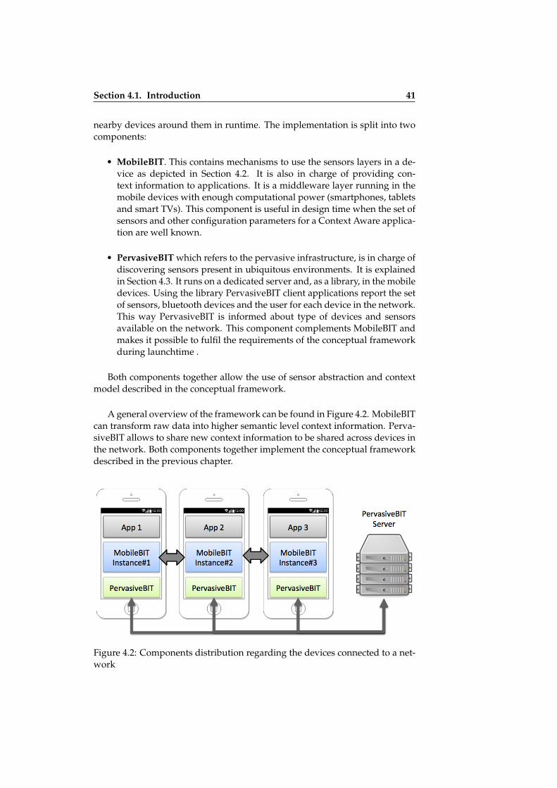
ii
ii
ii
ii
Section 4.1. Introduction 41
nearby devices around them in runtime. The implementation is split into twocomponents:
• MobileBIT. This contains mechanisms to use the sensors layers in a de-vice as depicted in Section 4.2. It is also in charge of providing con-text information to applications. It is a middleware layer running in themobile devices with enough computational power (smartphones, tabletsand smart TVs). This component is useful in design time when the set ofsensors and other configuration parameters for a Context Aware applica-tion are well known.
• PervasiveBIT which refers to the pervasive infrastructure, is in charge ofdiscovering sensors present in ubiquitous environments. It is explainedin Section 4.3. It runs on a dedicated server and, as a library, in the mobiledevices. Using the library PervasiveBIT client applications report the setof sensors, bluetooth devices and the user for each device in the network.This way PervasiveBIT is informed about type of devices and sensorsavailable on the network. This component complements MobileBIT andmakes it possible to fulfil the requirements of the conceptual frameworkduring launchtime .
Both components together allow the use of sensor abstraction and contextmodel described in the conceptual framework.
A general overview of the framework can be found in Figure 4.2. MobileBITcan transform raw data into higher semantic level context information. Perva-siveBIT allows to share new context information to be shared across devices inthe network. Both components together implement the conceptual frameworkdescribed in the previous chapter.
Figure 4.2: Components distribution regarding the devices connected to a net-work

ii
ii
ii
ii
42 Chapter 4. Implementation of the Conceptual Framework
4.2 MobileBIT
4.2.1 Introduction
MobileBIT is in charge of the abstraction layer of the sensors and the compo-sition of context information within a mobile device (a smartphone or tablet,for instance) in a ubiquitous environment. MobileBIT is implemented as anAndroid library designed following a modular approach. It is extensible andallows the use of external libraries to add compatibility with new processingmethods and sensor devices. In the following paragraphs, the main featuresand relevant details of MobileBIT are described.
MobileBIT framework [15], is based on a previous work of the PatternRecognition and Image Analysis group (PIA) of the Instituto Superior Técnico -Univeristy of Lisbon (IST-UL). It was adopted as the sensor abstraction compo-nent during a research stay in the PIA group, because it fitted the requirementsof the Igerri framework. Afterwards, we adopted, developed and extendedMobileBIT to make it suitable for Context-Aware applications.
4.2.2 Sensor-Driven Mobile Applications
MobileBIT hides issues with sensors when programming mobile applications,providing a common interface and mechanisms to access sensor data withoutdirectly manipulating them. It is intended to facilitate rapid-prototyping ofmobile applications for telemedicine and mobile health domains dealing withthe following tasks:
• Real-time data acquisition
• Data processing (e.g. filtering)
• Data recording or storing
• Communication with external servers (e.g. cloud storing/processing)
• Data visualization (e.g. progress charts)
For its extension to the Context-Aware domain, the following task were alsoincluded:
• Sensor data abstraction to provide context information
• Real-time generation of context information
• Communication with other devices with similar characteristics (e.g. othersmartphones or tablets)

ii
ii
ii
ii
Section 4.2. MobileBIT 43
4.2.3 Architecture of MobileBIT
The above mentioned tasks are divided and wrapped in software componentscalled Functional Blocks which can be reused for different applications. Atruntime, Functional Blocks are organised with a middleware layer known asWorkflow Manager (WFM) to allow the delivery of sensor data from one com-ponent to the next. This way, developers can design and build the functionalityof the mobile applications without being concerned about programming issuesrelated with sensors. These elements of the MobileBIT architecture were devel-oped for the Android operative system.
In order to specify which sensors are required and the tasks to be performedwith their data, a JSON based description language called Data Processing Lan-guage (DPL) was defined to describe the behaviour of the functional blocks.Finally, the user interface of the application is developed using Web based tech-nologies such as HTML, JavaScript and CSS.
MobileBIT follows a hybrid application approach [41]. These applicationscombine a Web layer with a Native layer. With regard to the sensors, Mo-bileBIT hides the data manipulation in the native layer and allows specific op-erations from the Web layer (e.g. start/stop protocols for acquiring data fromsensors). This way, developers rely on previously defined/programmed Func-tional Blocks to create a web application with the intended functionalities.
There are several reasons to follow the hybrid approach:
• Physical sensor programming issues are explicitly hidden using this ap-proach. Developers focus on the final applications and MobileBIT mod-ules deal with sensors.
• A web layer facilitates the developing of user interfaces to Web designersand developers. Developers can choose which Blocks to use and don’tneed to mind with Android programming issues. There is a large com-munity that MobileBIT can address using this approach.
• Applications benefits from the Javascript and CSS frameworks obtaininga professional look and feel in their user interfaces.
On the other hand, the performance of hybrid applications comparing tonative applications is always a drawback. If it is required, our conceptualframework allows to create Android native applications without the hybridapproach. Sensor data can be accessed from native applications, this option ismore suitable for developers with previous experience using the android plat-form.
A full overview of the architecture is depicted in Figure 4.3.
Summarizing, MobileBIT includes four mechanisms that makes it usefulfor the development of sensor-driven mobile applications:
• Functional Blocks
• Data Processing Language

ii
ii
ii
ii
44 Chapter 4. Implementation of the Conceptual Framework
Figure 4.3: Architecture of the MobileBIT Framework for Sensor driven mobileapplications
• Workflow Manager
• Web based user interfaces
The framework was extended and modified providing mechanisms for theContext-Aware domain. For these applications, the Web layer can obtain con-text information using an event driven approach. When new context informa-tion is generated it is registered and delivered to the JavaScript layer. Finally,developers decide how to use this information appropriately in Context-Awareapplications.
Functional Blocks
Functional blocks are the basic components of MobileBIT. Every block encap-sulates common tasks for applications dealing with sensors. The blocks com-municate following the observer pattern and share information at runtime withthe mobile applications.
Functional Blocks use the concept of "channel" to stream the data from oneblock to the next one. There are two different types of channels regarding thedirection that follows the stream of data, input channel and output channel.
A Functional Block may require a specific amount of data in an input chan-nel (sample size) to successfully fulfil a task. The values obtained are deliveredto the next block using the output channel. For instance, processing data froman accelerometer with a specific fixed sampling rate of 100Hz can require 20samples in order to obtain a valid processed value. This means that every 200

ii
ii
ii
ii
Section 4.2. MobileBIT 45
milliseconds there will be enough data in the Functional Block to process thetask. In one second, the block can generate 5 new values (or a data set of 5datum) in the output. In order to make the Functional Blocks compatible witheach other, they can be configured using parameters (for instance, the samplerate). In this way, Functional Blocks can be reused several times.
There is no restriction in the number of input/output channels required foreach Functional Block. However, MobileBIT distinguishes three types:
• Source Blocks (No input channel and 1 to N output channels) are dataacquisition devices (for instance, the Bitalino Board) and they wrap theconnection with external devices (e.g. Bluetooth communication proto-col). As a consequence, networking issues are hidden to developers. Inaddition all sensors can be used and activated in the same way, achievinga homogeneous access to the data of the sensors from MobileBIT.
• Sink Blocks (1 to N input channels and no output channel) are aimed atrecording, communicating and visualizing the data.
– When it comes to record/storage of the data, these are used to createlogs of the outputs of some Blocks in the flash memory of the device.
– With regard to communication, Sink Blocks are used for remote stor-age or for feeding with data services in the cloud. For this purpose,they use network protocols such as WebSockets.
– There are also blocks devoted to data visualization for the final users.These Sink Blocks usually require some code in the web layer toproperly adapt the visualization to the mobile application.
– Finally, Sink Blocks can be used to deliver context information to theWeb layer with an event driven approach. In this case the developerhas to deal with this information and adapt the behaviour of themobile application accordingly.
• Normal Blocks (1 to N Input and 1 to N output channels) are designed forprocessing the sensor data streams and combining properties of sourceand sink blocks. They can be programmed to use an external server toprocess the data, or use the same device to do this task. When there isenough data in the input channels they are processed and the results aredelivered to the next Functional Block. On the one hand, several inputscan be used to perform complex data processing (e.g. Machine Learningalgorithms), on the other hand, several outputs can be used to providedifferent feature extraction at the same time to the next block.
Functional Blocks are the representation of the Sensors as described in theLayered Conceptual framework of Chapter 3. Physical Sensor are implementedas Source Blocks. Virtual Sensors are implemented as Normal Blocks. The layerof abstract sensors is implemented by PervasiveBIT.
Functional Blocks are programmed once and then reused for any mobileapplications when required. For this purpose, MobileBIT includes a set of
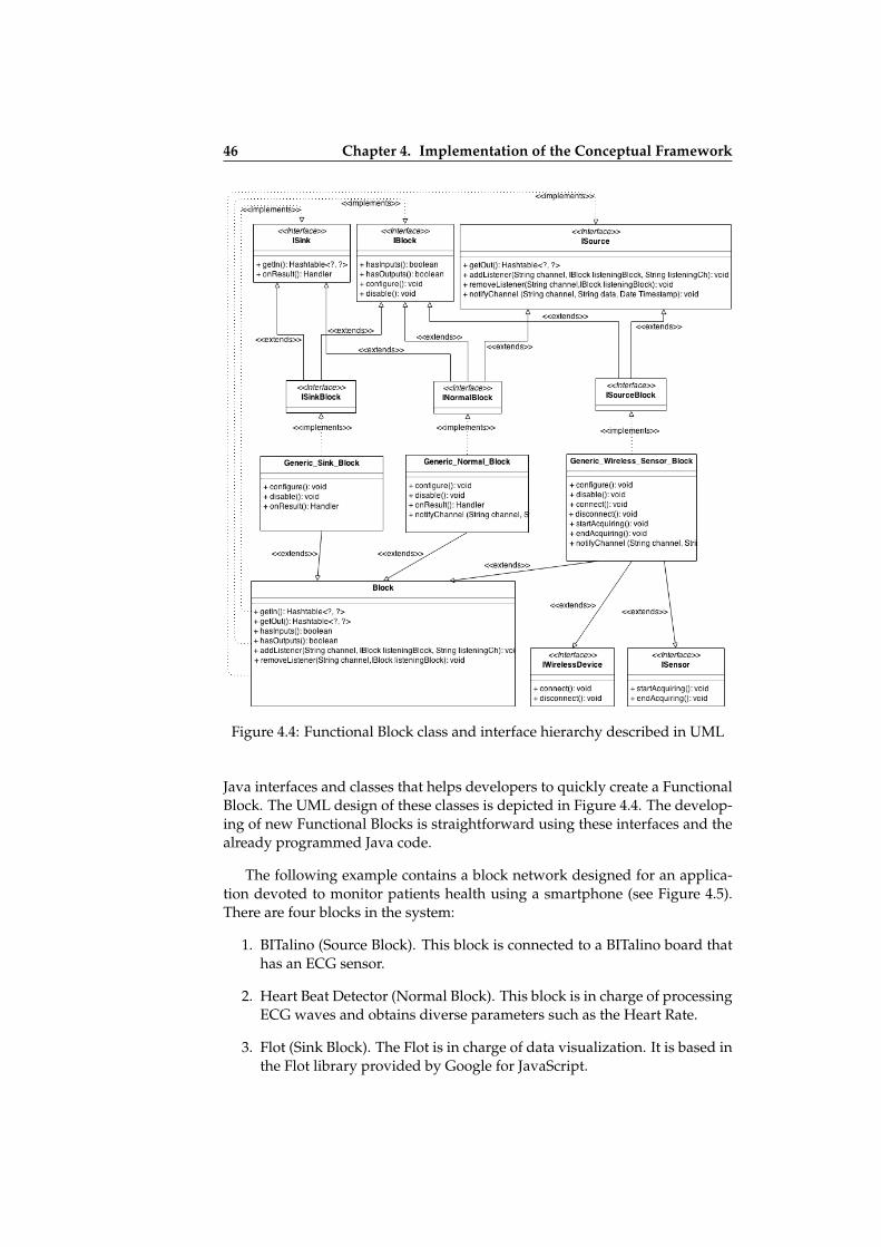
ii
ii
ii
ii
46 Chapter 4. Implementation of the Conceptual Framework
Figure 4.4: Functional Block class and interface hierarchy described in UML
Java interfaces and classes that helps developers to quickly create a FunctionalBlock. The UML design of these classes is depicted in Figure 4.4. The develop-ing of new Functional Blocks is straightforward using these interfaces and thealready programmed Java code.
The following example contains a block network designed for an applica-tion devoted to monitor patients health using a smartphone (see Figure 4.5).There are four blocks in the system:
1. BITalino (Source Block). This block is connected to a BITalino board thathas an ECG sensor.
2. Heart Beat Detector (Normal Block). This block is in charge of processingECG waves and obtains diverse parameters such as the Heart Rate.
3. Flot (Sink Block). The Flot is in charge of data visualization. It is based inthe Flot library provided by Google for JavaScript.
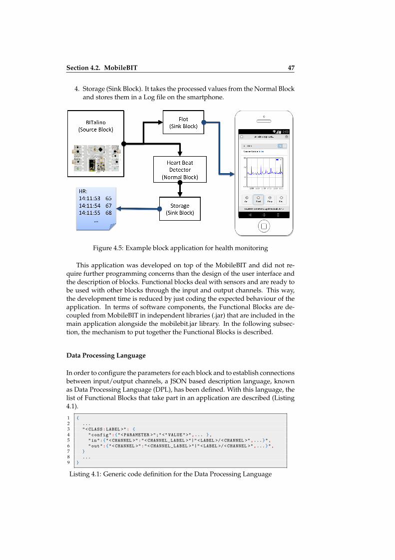
ii
ii
ii
ii
Section 4.2. MobileBIT 47
4. Storage (Sink Block). It takes the processed values from the Normal Blockand stores them in a Log file on the smartphone.
Figure 4.5: Example block application for health monitoring
This application was developed on top of the MobileBIT and did not re-quire further programming concerns than the design of the user interface andthe description of blocks. Functional blocks deal with sensors and are ready tobe used with other blocks through the input and output channels. This way,the development time is reduced by just coding the expected behaviour of theapplication. In terms of software components, the Functional Blocks are de-coupled from MobileBIT in independent libraries (.jar) that are included in themain application alongside the mobilebit.jar library. In the following subsec-tion, the mechanism to put together the Functional Blocks is described.
Data Processing Language
In order to configure the parameters for each block and to establish connectionsbetween input/output channels, a JSON based description language, knownas Data Processing Language (DPL), has been defined. With this language, thelist of Functional Blocks that take part in an application are described (Listing4.1).
1 {2 ...3 "<CLASS:LABEL >": {4 "config":{"<PARAMETER >";"<" VALUE">",... },5 "in":{"<CHANNEL >":"<CHANNEL_LABEL >"|"<LABEL >/<CHANNEL >",...}",6 "out":{"<CHANNEL >":"<CHANNEL_LABEL >"|"<LABEL >/<CHANNEL >",...}",7 }8 ...9 }
Listing 4.1: Generic code definition for the Data Processing Language

ii
ii
ii
ii
48 Chapter 4. Implementation of the Conceptual Framework
For every Functional Block four elements have to be defined:
• Identification labels. Every Functional Block is identified using the classname of the library which implements that Block. There is also a label toallow calls to the Functional Block from the Web layer.
• Configuration parameters. Functional Blocks are configurable for someparameters. For instance, when there is a Source Block for a Sensor, crit-ical values are: the sampling rate, the number of samples required toobtain a frame (window size) and parameters related to scaling and theamplitude of the data. For other blocks, e.g. Sink block for Storage, thename of the file to store the log or whether it uses internal or externalmemory (flash vs. microSD) are specified.
• Output channels. These specify the paths from the sensors to the se-lected inputs of Functional Blocks. For instance, a Source Block for aSensor board can have as many output channels as sensors. In the caseof Normal Blocks for feature extraction of a signal, they can have differ-ent outputs for all the available features. Output channels are labelledwith a number and a text. While the number is used only to show thechannel data addressed, the text label is an identification for the rest ofthe blocks to refer to that output channel. Sink Functional Blocks do nothave Output channels.
• Input channels. They represent the input data required to activate a taskin a Normal or Sink Block. They refer to other Functional Blocks Outputchannels that are connected to the present block. Input channels, like theoutputs, have a number and a text. Although the number has a similarmeaning, the label refers to other blocks channels.
The behaviour of the sensor data can be described using this language. Thecomplexity of the DPL file expands when the number of sensors and tasks tobe performed increases. The three types of Functional blocks are differentlydesigned and are combined together to set up the network. In the followingexample, Listing 4.2 (shortened in Table 4.1), the DPL file is described. TheseFunctional Blocks were presented in the previous subsection Figure 4.5.
When the DPL File is loaded in the MobileBIT, the file is parsed. If thereis no problem, the behaviour of the sensors and communication channels be-tween blocks is established. In the next subsection, the module in charge ofthe correct creation and maintenance of the block network is described. Addi-tional DPL Files used during the evaluation and testing of the framework canbe found in Appendix A.
Workflow Manager
The Workflow Manager (WFM) is the core of the MobileBIT framework. Themain goal of the WFM is to automatically handle the subscription betweenblocks following the Observer Pattern [?]. To this end, WFM requires a DPLFile to access the libraries of all the Functional Blocks used in the DPL. The

ii
ii
ii
ii
Section 4.2. MobileBIT 49
DPL file has to be properly formatted and it has to follow the design rules men-tioned in the previous subsection. Otherwise WFM will raise an error warning.Additionally, the WFM allow access to every instance of the system, allowingdirect manipulation of the Blocks from the applications user interface. By thismechanism, the users can trigger the acquisition of sensor data on demand ormodify some parameters of the blocks.
1 {2 "BitalinoBlock:Sensor":{3 "config":{4 "MACaddress": 11:22:33:44:55:66,5 "Mode":"LIVE",6 "SamplingRate":100",7 "FrameNumber":30"8 },9 "in":{},
10 "out":{11 "3":"ECG"12 }13 },14 "HeartRateAlgorithm:HeartBeatDetector":{15 "config":{},16 "in":{17 "1":"ECG"18 },19 "out":{20 "1":"HR"21 }22 },23 "FlotBlock:ProgressionChart":{24 "config":{25 "FileName":"HR_log",26 "Frames":3027 },28 "in":{29 "1":"ECG"30 },31 "out":{}32 },33 "StorageBlock:HeartRateLog":{34 "config":{35 "FileName":"HR_log",36 "Frames":137 },38 "in":{39 "1":"HR"40 },41 "out":{}42 }43 }
Listing 4.2: Example JSON DPL for an eHealth application
Table 4.1: Information of the Functional blocks contained in the DPL used forthe eHealth application example
Functional Block Type Input From Output To
BITalino Source - - 3: ECGHeartBeatDetectorProgressionChart
HeartBeatDetector Normal 1: ECG BITalino 1: HR HeartRateLogHeartRateLog Sink 1: HR HeartBeatDetector -
ProgressionChart Sink 1: ECG BITalino -
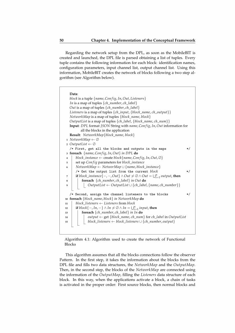
ii
ii
ii
ii
50 Chapter 4. Implementation of the Conceptual Framework
Regarding the network setup from the DPL, as soon as the MobileBIT iscreated and launched, the DPL file is parsed obtaining a list of tuples. Everytuple contains the following information for each block: identification names,configuration parameters, input channel list, output channel list. Using thisinformation, MobileBIT creates the network of blocks following a two step al-gorithm (see Algorithm below).
Data:block is a tuple {name, Con f ig, In, Out, Listeners}In is a map of tuples {ch_number, ch_label}Out is a map of tuples {ch_number, ch_label}Listeners is a map of tuples {ch_input, {block_name, ch_output}}NetworkMap is a map of tuples {block_name, block}OutputList is a map of tuples {ch_label, {block_name, ch_num}}Input: DPL format JSON String with name, Con f ig, In, Out information for
all the blocks in the applicationResult: NetworkMap{block_name, block}
1 NetworkMap← ∅2 OutputList← ∅/* First, get all the blocks and outputs in the maps */
3 foreach {name, Con f ig, In, Out} in DPL do4 block_instance← create block{name, Con f ig, In, Out, ∅}5 set up Con f ig parameters for block_instance6 NetworkMap← NetworMap ∪ {name, block_instance}
/* Get the output list from the current block */7 if block_instance{−,−, Out} ∧Out 6= ∅ ∧Out =
⋃ni=1 outputi then
8 foreach {ch_number, ch_label} in Out do9 OutputList← OutputList ∪ {ch_label, {name, ch_number}}
/* Second, assign the channel listeners to the blocks */10 foreach {block_name, block} in NetworkMap do11 block_listeners← Listeners from block12 if block{−, In,−} ∧ In 6= ∅ ∧ In =
⋃ni=1 inputi then
13 foreach {ch_number, ch_label} in In do14 output← get {block_name, ch_num} for ch_label in OutputList15 block_listeners← block_listeners ∪ {ch_number, output}
Algorithm 4.1: Algorithm used to create the network of FunctionalBlocks
This algorithm assumes that all the blocks connections follow the observerPattern. In the first step, it takes the information about the blocks from theDPL file and fills two data structures, the NetworkMap and the OutputMap.Then, in the second step, the blocks of the NetworkMap are connected usingthe information of the OutputMap, filling the Listeners data structure of eachblock. In this way, when the applications activate a block, a chain of tasksis activated in the proper order: First source blocks, then normal blocks and
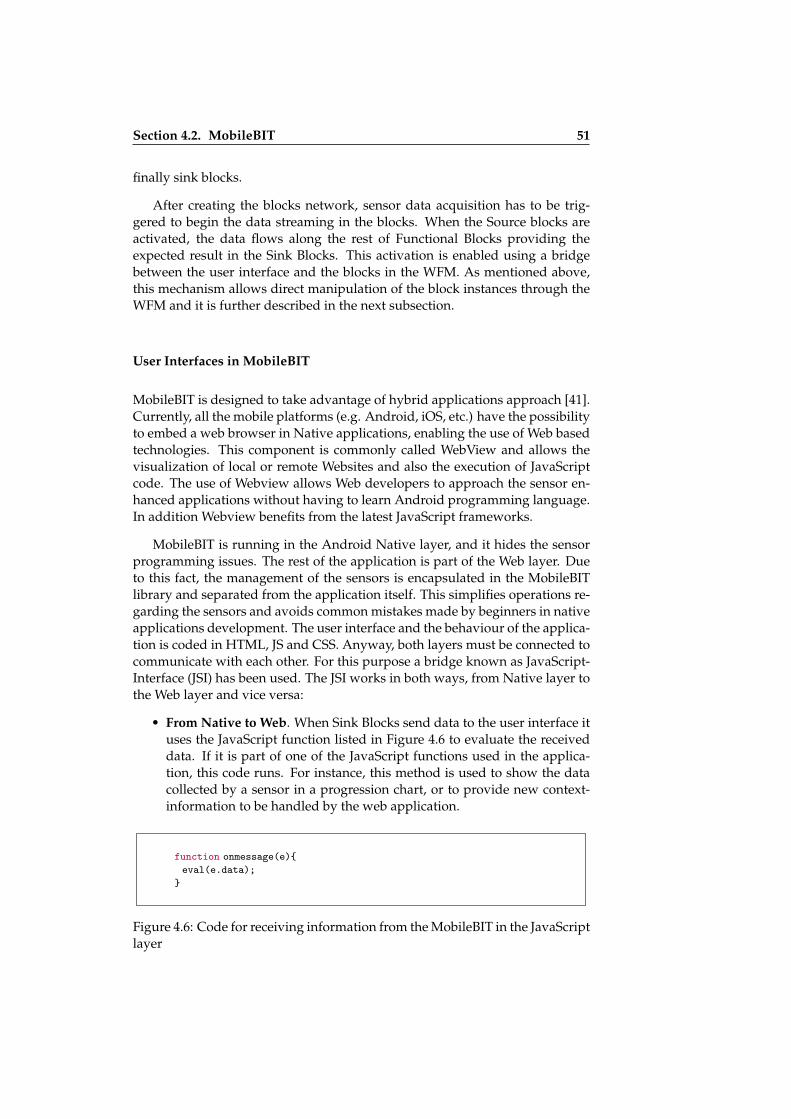
ii
ii
ii
ii
Section 4.2. MobileBIT 51
finally sink blocks.
After creating the blocks network, sensor data acquisition has to be trig-gered to begin the data streaming in the blocks. When the Source blocks areactivated, the data flows along the rest of Functional Blocks providing theexpected result in the Sink Blocks. This activation is enabled using a bridgebetween the user interface and the blocks in the WFM. As mentioned above,this mechanism allows direct manipulation of the block instances through theWFM and it is further described in the next subsection.
User Interfaces in MobileBIT
MobileBIT is designed to take advantage of hybrid applications approach [41].Currently, all the mobile platforms (e.g. Android, iOS, etc.) have the possibilityto embed a web browser in Native applications, enabling the use of Web basedtechnologies. This component is commonly called WebView and allows thevisualization of local or remote Websites and also the execution of JavaScriptcode. The use of Webview allows Web developers to approach the sensor en-hanced applications without having to learn Android programming language.In addition Webview benefits from the latest JavaScript frameworks.
MobileBIT is running in the Android Native layer, and it hides the sensorprogramming issues. The rest of the application is part of the Web layer. Dueto this fact, the management of the sensors is encapsulated in the MobileBITlibrary and separated from the application itself. This simplifies operations re-garding the sensors and avoids common mistakes made by beginners in nativeapplications development. The user interface and the behaviour of the applica-tion is coded in HTML, JS and CSS. Anyway, both layers must be connected tocommunicate with each other. For this purpose a bridge known as JavaScript-Interface (JSI) has been used. The JSI works in both ways, from Native layer tothe Web layer and vice versa:
• From Native to Web. When Sink Blocks send data to the user interface ituses the JavaScript function listed in Figure 4.6 to evaluate the receiveddata. If it is part of one of the JavaScript functions used in the applica-tion, this code runs. For instance, this method is used to show the datacollected by a sensor in a progression chart, or to provide new context-information to be handled by the web application.
function onmessage(e){eval(e.data);
}
Figure 4.6: Code for receiving information from the MobileBIT in the JavaScriptlayer

ii
ii
ii
ii
52 Chapter 4. Implementation of the Conceptual Framework
• From Web to Native. When the application calls a method of the func-tional blocks it uses a similar code to the one listed in Figure 4.7. In thecase of this Figure, calling send(’Sensor.startAcquiring()’); a function startsacquiring data from a Source Block labelled as Sensor in the DPL of theapplication. The commands are received by the WFM and parsed to callthe specified method in the Functional Block. This method’s calls areasynchronous. Return values and error information are obtained withthe callbacks listed in Figure 4.8. Asynchronous behaviour is required togrant a fluent interaction with the user interface of the applications. Thesequence to send a command and receive a response is depicted in Figure4.9.
window.wv.send(‘Sensor.startAcquiring()’);
Figure 4.7: Code for calling a method in a Functional Block named Sensor
function done(cmd, val);function error(cmd, val);
Figure 4.8: Callbacks to get the result for the Functional Blocks functions
Figure 4.9: Sequence diagram for the call to functions
JSI is designed to be compatible with the semantics of WebSockets [29]. Atdeveloping time, the user interface can be instrumented and accessed remotelyfrom the a desktop computer, making it easier to debug from a conventionalWeb Browser rather than the embedded browser.
Some Sink Blocks structure and organize data from sensors for plotting li-

ii
ii
ii
ii
Section 4.2. MobileBIT 53
braries. Although it would be expected to have the visualization as an exclu-sive task for applications developers, this is very useful for rapid prototypingsensor-driven applications that need real time progress charts. Sink Blocks re-lated to the visualization of the data in the user interface are designed to usethe functionalities of JavaScript frameworks like JQuery Mobile1 and other li-braries to improve the presentation of the data to the end user. For instance,figure 4.10 shows two screenshots of the example application for heart ratemonitoring. A notification message based on JQuery Mobile is displayed inScreenshot a. In a similar way Screenshot b shows the Flot library2 for plottingcharts.
Screenshot a Screenshot b
Figure 4.10: User interface of the example application
4.2.4 Context-Aware Support for MobileBIT
Context Aware applications use the context information for many purposes.For instance, to adapt the graphical user interface or to consider new interac-tion modalities. MobileBIT has been extended so as to be useful for the creationof Context-Aware applications.
1http://jquerymobile.com/2http://www.flotcharts.org/
ii
ii
ii
ii
54 Chapter 4. Implementation of the Conceptual Framework
Rationale for the Adoption of MobileBIT
As was explained in Chapter 3, the Igerri framework considers a series of layersin order to deal with sensors. These concepts are represented in the MobileBITframework by means of the Functional blocks and the DPL. MobileBIT Func-tional Blocks are the implementation of the different types of sensors describedin Igerri:
• Igerri’s Physical Sensors are built by means the Source Blocks. The maindifference with the conceptual framework is that the Source Block repre-sent all the sensors grouped by device instead of presenting them one byone. Nevertheless, this difference is not relevant for the final application,since the DPL allows only the sensors required for the application to bedescribed.
• Igerri’s Virtual Sensors are built using Normal Blocks. By means of pro-cessing techniques other physical and virtual sensors can be transformedinto a new Virtual sensor.
• Igerri’s Abstract Sensors are not explicitly built as a different FunctionalBlock but as a simplification of the above mentioned Source and NormalBlocks.
• Igerri’s Context Services are built using Sink Blocks. Sink Blocks commu-nicate with the application and deliver context-information to the appli-cation.
It is possible to have the same context aware application running for differ-ent DPL files with MobileBIT. This feature is necessary to obtain Abstract sen-sors because it allows the interchange of a DPL file by another one maintainingthe context aware application up to date with equivalent context information.
Besides the encapsulation of sensor abstraction in Functional Blocks, the de-sign of MobileBIT allows the decoupling of the user interface. The separationof the sensor abstraction concerns from the Context-Aware application devel-opment is implicit in the design. MobileBIT is in charge of sensor issues andthe Web layer contains the methods necessaries to create Context-Aware appli-cations. Additionally the use of a Web layer makes MobileBIT compliant withthe approach followed in Egoki meeting the requirements stated in Chapter 1for this thesis.
Nonetheless a mechanism to have access to the context information fromthe Web layer has to be specified. But a new type of block that can handle thecontext in a similar way as the Context Services specify can be easily added.The following lines explains how to deliver context to the MobileBIT applica-tion.

ii
ii
ii
ii
Section 4.2. MobileBIT 55
Context Delivery Mechanism
The delivery of context information to the Web layer is the first step in or-der to design and develop new Context-Aware applications. We modelled thecontext-information as the tuple:
context-information ≡ { Entity, Context, Value, TimeStamp }
To achieve this MobileBIT uses a special Sink Block called Context Block.Context Blocks are the implementation of the Context Services in the Concep-tual Framework. This Block receives from an input channel the information tobe delivered to the Web Layer as context. It has two main features:
• Specific configuration parameters to deal with context information fromother Normal blocks.
• A callback function to be used with the JSI that has to be implemented bythe Context-Aware application.
Functional blocks can produce context information that is not valid for aspecific Context-Aware application. This happens when a Normal Block isused for several purposes. For instance, EMG electrodes can be attached tomany muscles but the Normal Block to process the EMG signals have to bereconfigured each time to indicate which muscle has been measured or whichmovement has taken place. It also happens with general purpose sensors suchas accelerometers. In order to make the Blocks more reusable, this block re-names and formats the context information for each application. The followingconfiguration parameters were used for the Context Block:
• Entity refers to the person, object or place which characterizes the contextinformation.
• Context refers to the action or event taking place for the above mentionedentity.
• ValuesMap are the specific values that will be delivered to the Web layer.They are mapped taking into account the values that are obtained in theinput channel. If there is not a values-map specified for the block, theContext Block just conveys to the Web layer the input values enrichedwith the Entity - Context values.
• Notification refers to the way the Context Block and the Web layer com-municate:
– All. Every time new data arrives to the Context Block using theinput channel it is delivered to the Web layer.
– Updates. The Web layer is notified only when there is a change inthe context-information values. Sometimes, the previous notifica-tion mode (All) may deliver exactly the same context informationvalues. To avoid this unnecessary repetition, this mode will only
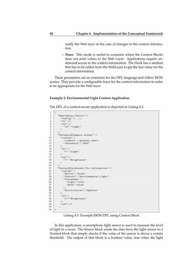
ii
ii
ii
ii
56 Chapter 4. Implementation of the Conceptual Framework
notify the Web layer in the case of changes in the context informa-tion.
– None. This mode is useful in scenarios where the Context Blocksdoes not send values to the Web Layer. Applications require on-demand access to the context-information. The block has a methodthat has to be called from the WebLayer to get the last value for thecontext information.
These parameters are an extension for the DPL language and follow JSONsyntax. They provide a configurable layer for the context-information in orderto be appropriate for the Web layer.
Example 1: Environmental Light Context Application
The DPL of a context-aware application is depicted in Listing 4.3.
1 {2 "Smartphone:Sensor":{3 "config":{...},4 "in":{},5 "out":{6 "10":"Light"7 }8 },9 "ThresholdCompare:normal":{
10 "config":{11 "compare":"greater_than",12 "threshold":"1000"13 },14 "in":{15 "1":"Light"16 },17 "out":{18 "1":"Brightness"19 }20 },21 "ContextBlackboard:Ctx -information":{22 "config":{23 "Entity":"Room",24 "Context":"Environmental_light",25 "ValuesMap":{26 "Light":true,27 "Dark":false28 },29 "Notification":"Updates"30 },31 "in":{32 "1":"Brightness"33 },34 "out":{}35 }36 }
Listing 4.3: Example JSON DPL using Context Block
In this application, a smartphone light sensor is used to measure the levelof light in a room. The Source block sends the data from the light sensor to aNormal block that simply checks if the value of the sensor is above a certainthreshold. The output of that block is a boolean value, true when the light

ii
ii
ii
ii
Section 4.2. MobileBIT 57
value is over the threshold and false in other case. Thus, in the Context Block,the input values are mapped to Light when the value of the sensor is over thethreshold and Dark if the value is under the threshold. Finally, the ContextAware application only needs to adapt its behaviour to the context informa-tion. This is a straightforward use of the Context block to better explain howit works. However, the real importance of the context renaming comes whenthere is need to reuse the same Functional Block for different purposes.
Example 2: Arm Gestures Context Application
The activity in the right arm biceps is measured in the application described inListing 4.4. For that purpose a EMG sensor from the BITalino board is used.EMG data are filtered and processed to obtain values periodically. These val-ues have an implicit semantic regarding the muscle state in the output of theNormal Block. The application returns the values contracted or relaxed depend-ing on the input. Application developers aimed to use this muscle contractiondetector block to associate it to two different muscles, the biceps of the rightarm and the thenar eminence of the right hand. Therefore they had to relabelthe context information of the Normal Block and obtain different values in theWeb layer.
All the context-information is delivered to the web application using the JSIbridge. For this purpose the application developer has to include and completethe following function in the JavaScript code.
function perceived(context , value){// Developers code for context aware application ...
}
The first parameter (context) contains a complete description of the infor-mation required to understand ’value’ and the second parameter is the context-information value itself.
4.2.5 Guidelines to Improve the Performance
The performance of the MobileBIT applications is an important concern anddepending on the sensor sampling rate when dealing with data intensive ap-plications the streams of data flowing through the chain of blocks can sufferperformance drops and bottlenecks. Usually, sampling rates over 100Hz areproblematic in modest or inexpensive smartphones if the application doesn’taddress the performance issues properly. The main evidence for these prob-lems is that the user interface lags and in the most extreme cases, is blocked,which has an undesirable impact on the usability of the applications.
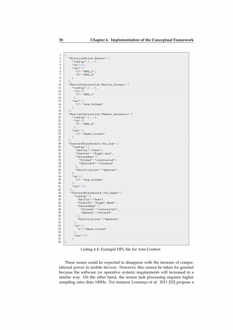
ii
ii
ii
ii
58 Chapter 4. Implementation of the Conceptual Framework
1 {2 "BitalinoBlock:Sensor":{3 "config":{...},4 "in":{},5 "out":{6 "1":"EMG_1",7 "3":"EMG_2"8 }9 },
10 "MuscleContraction:Muscle_biceps":{11 "config":{...},12 "in":{13 "1":"EMG_1"14 },15 "out":{16 "1":"Arm_folded"17 }18 },19 "MuscleContraction:Thenar_eminence":{20 "config":{...},21 "in":{22 "1":"EMG_2"23 },24 "out":{25 "1":"Hand_closed"26 }27 },28 "ContextBlackboard:Ctx_arm":{29 "config":{30 "Entity":"User",31 "Context":"Right:Arm",32 "ValuesMap":{33 "Folded":"contracted",34 "Unfolded":"relaxed"35 },36 "Notification":"Updates"37 },38 "in":{39 "1":"Arm_folded"40 },41 "out":{}42 },43 "ContextBlackboard:Ctx_hand":{44 "config":{45 "Entity":"User",46 "Context":"Right:Hand",47 "ValuesMap":{48 "Closed":"contracted",49 "Opened":"relaxed"50 },51 "Notification":"Updates"52 },53 "in":{54 "1":"Hand_closed"55 },56 "out":{}57 }58 }
Listing 4.4: Example DPL file for Arm Context
These issues could be expected to disappear with the increase of compu-tational power in mobile devices. However, this cannot be taken for grantedbecause the software (or operative system) requirements will increased in asimilar way. On the other hand, the sensor task processing requires highersampling rates than 100Hz. For instance Lourenço et al. 2011 [52] propose a
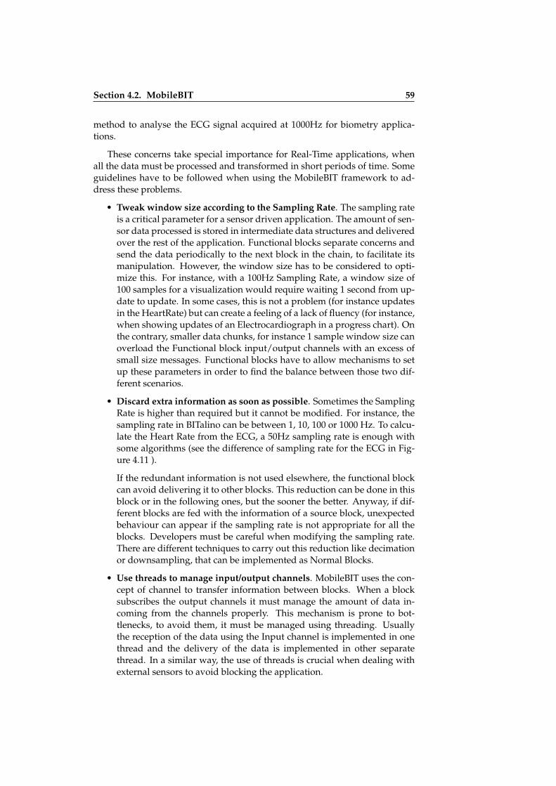
ii
ii
ii
ii
Section 4.2. MobileBIT 59
method to analyse the ECG signal acquired at 1000Hz for biometry applica-tions.
These concerns take special importance for Real-Time applications, whenall the data must be processed and transformed in short periods of time. Someguidelines have to be followed when using the MobileBIT framework to ad-dress these problems.
• Tweak window size according to the Sampling Rate. The sampling rateis a critical parameter for a sensor driven application. The amount of sen-sor data processed is stored in intermediate data structures and deliveredover the rest of the application. Functional blocks separate concerns andsend the data periodically to the next block in the chain, to facilitate itsmanipulation. However, the window size has to be considered to opti-mize this. For instance, with a 100Hz Sampling Rate, a window size of100 samples for a visualization would require waiting 1 second from up-date to update. In some cases, this is not a problem (for instance updatesin the HeartRate) but can create a feeling of a lack of fluency (for instance,when showing updates of an Electrocardiograph in a progress chart). Onthe contrary, smaller data chunks, for instance 1 sample window size canoverload the Functional block input/output channels with an excess ofsmall size messages. Functional blocks have to allow mechanisms to setup these parameters in order to find the balance between those two dif-ferent scenarios.
• Discard extra information as soon as possible. Sometimes the SamplingRate is higher than required but it cannot be modified. For instance, thesampling rate in BITalino can be between 1, 10, 100 or 1000 Hz. To calcu-late the Heart Rate from the ECG, a 50Hz sampling rate is enough withsome algorithms (see the difference of sampling rate for the ECG in Fig-ure 4.11 ).
If the redundant information is not used elsewhere, the functional blockcan avoid delivering it to other blocks. This reduction can be done in thisblock or in the following ones, but the sooner the better. Anyway, if dif-ferent blocks are fed with the information of a source block, unexpectedbehaviour can appear if the sampling rate is not appropriate for all theblocks. Developers must be careful when modifying the sampling rate.There are different techniques to carry out this reduction like decimationor downsampling, that can be implemented as Normal Blocks.
• Use threads to manage input/output channels. MobileBIT uses the con-cept of channel to transfer information between blocks. When a blocksubscribes the output channels it must manage the amount of data in-coming from the channels properly. This mechanism is prone to bot-tlenecks, to avoid them, it must be managed using threading. Usuallythe reception of the data using the Input channel is implemented in onethread and the delivery of the data is implemented in other separatethread. In a similar way, the use of threads is crucial when dealing withexternal sensors to avoid blocking the application.

ii
ii
ii
ii
60 Chapter 4. Implementation of the Conceptual Framework
Figure 4.11: In these pictures, the ECG signal is acquired using two differentsampling rates. In the left side, the rate is 100Hz (the top one (a) is downsam-pled to 50Hz and the bottom one (b) is the original). On the right side (c) thesampling rate is with 1000Hz.
• Be careful with the performed tasks. Some tasks require several itera-tions and loops and a considerable amount of time to be performed, inaddition this can have a negative effect in the battery charge and proces-sor performance. Sometimes, it is better to send the values to an externalserver than to try to process all the data in a Normal Block. A carefulevaluation must be made concerning which option is more adequate forprocessing heavy tasks.
• Avoid overloading the user interface. When the Sink blocks are con-nected to the user interface, a mechanism to deliver the information fromthe native layer to the web layer is used periodically to update the userinterface using the event driven approach. There can be problems if thenumber of JavaScript events per seconds are too high. To reduce thelikelihood of this problem, the data to be delivered to the user interfaceshould be accumulated in the same event.
If poor performance is detected in an application that implements MobileBIT,these recommendations should be carefully followed.
ii
ii
ii
ii
Section 4.3. PervasiveBIT 61
4.3 PervasiveBIT
4.3.1 Introduction
So far the implementation has dealt with device internal issues in developmenttime. Nevertheless, Context-Aware applications often requires to interoperatebetween several devices. For this purpose, the PervasiveBIT component wasdesigned.
PervasiveBIT works as a component to ease the connection between devicesand external sensors in run time. Mobile Context-Aware applications can workin an opportunistic way: depending on the number of devices and sensors inthe network some applications will work or not. Additionally, informationthat is not available in development time is required. For instance, the MACaddress for a Bluetooth sensor or the IP address of a device. Therefore, thiscomponent implements the transformation from the virtual sensor layer to thephysical layer explained in the Conceptual Framework.
4.3.2 SensorHub: Automatic Discovery of Sensors
PervasiveBIT includes a module called SensorHub that was developed to gatherinformation about the different types of sensors available in a device. Thismodule works for both internal sensors and externally connected sensors (e.g.via Bluetooth). This mechanism is divided in two parts:
• A library for each device that stores all the information and organizes it.
• A server application in the local network that receives the informationabout all the devices using PervasiveBIT.
In this way, it is possible to list the devices and sensors available, as wasmentioned in Chapter 3. With this information is also possible to know whichcontext-information will be available on every mobile device and to know if anapplication will work with the information available.
These features are necessary to discover all the sensors available to theContext-Aware application. This information is used to create the repositoryof elements of the Physical Layer of Physical Sensors (PLPS) as defined in theConceptual Framework.
4.3.3 SENSONTO: A Knowledge Base for Context Perception
A knowledge base was designed in order to store the parameters to enable thesensor abstraction and the creation of virtual sensors described in Igerri. Thisknowledge base contains concepts that are relevant to discover the availablecontext-information. The following elements required for ubiquitous comput-ing are conceptualized:

ii
ii
ii
ii
62 Chapter 4. Implementation of the Conceptual Framework
• Device contains a set of sensors that have network interfaces to be con-nected to a network and also provide information of the user and its lo-cation. The Devices run the context-aware applications.
• Sensors include the three categories considered for the categorization ofsensors proposed by Egoki: Physical, Virtual and Abstract sensors.
• Network interfaces to communicate the data with other devices usingNetworks.
• Users are entities to characterize the context-information. He/she is alsointeracting with the application and the device. The location of the useris also a relevant concept.
• Context-Information, is the relevant information to be perceived in theContext-Aware application. It contains all the lexicon for the Context.
To enable the perception of context-information these concepts must be partof the system. The relation of the concepts is depicted in Figure 4.12.
Figure 4.12: Conceptualization of elements in a Ubiquitous System
These elements are implemented in an Ontology called SENSONTO, whichis populated with the information gathered by the SensorHUB. It also containsthe lexicon to be used by the applications developers. With the additional in-formation about the modules collected by MobileBIT, it is possible to knowwhich Physical Sensors can be used to create new Virtual Sensors.

ii
ii
ii
ii
Section 4.3. PervasiveBIT 63
4.3.4 DPL Generation to Instantiate the Conceptual Framework
PervasiveBIT has two modules with well defined functionalities. Firstly, Sen-sorHub to gather information about the current status of the ubiquitous system(devices, sensors, networks). Secondly, SENSONTO to discover parameters toobtain the context services available for the applications. This process is mainlydone by a Server, through the transformations processes detailed in the follow-ing paragraphs.
Bottom-up Approach to Igerri Translation Transformations
PervasiveBIT obtains a list of Sensors and Context Services for every abstrac-tion layer in the Conceptual Model (See Figure 4.13).
Figure 4.13: A bottom up perspective of the implementation comparing it tothe conceptual framework
The lists are filled out following a bottom-up path in a four-step process:
1. The SensorHUB gathers information about all the devices and sensors inthe networks. This information is shared with the PervasiveBIT server. Itis used to build a list of physical sensors.
2. For every physical sensor in PervasiveBIT, a virtual sensor is created.During this process new virtual sensors from combinations of input fromsimpler virtual sensors are also created. These Combined Virtual Sensorsare discovered using the information available in SENSONTO. It mapswith the Virtualization Translation of the conceptual framework.
ii
ii
ii
ii
64 Chapter 4. Implementation of the Conceptual Framework
3. The abstract sensors matched to each virtual sensors are listed. This steprequires the use of SENSONTO to discover how virtual and abstract sen-sors are matched. It maps with the Abstraction Translation of the concep-tual framework.
4. The context service is generated based on the list of available AbstractSensors, again with the help of SENSONTO. The context informationwill enable the use of words from the Lexicon. It maps with the Con-text Translation of the conceptual framework.
When the process is completed all the information about the sensors isavailable. Thus when a Context Aware application requires it, the DPL gen-erator using this information creates the correct Workflow between blocks.
Top-down Approach to Igerri Request Transformations
The main function of PervasiveBIT is the generation of valid DPL code forapplications following the Igerri Conceptual Framework layered model. Inorder to do this, all the elements available in the model are identified startingwith the Physical Layer and ending with the Context Service layer. This isa bottom up approach to discover all the perceivable context in the system.Then, a DPL file is created by requesting information to all the layers createdin the previous step. The creation of the DPL follows a top-down approach tocheck which elements are available.
When the developer knows which context information is required for theapplication he or she calls the PervasiveBIT to obtain a valid DPL for the de-vices available in the system. This process is opposite to the previous one. It isalso composed of four steps:
1. Developers indicate which context names from the Lexicon are used. Apseudo DPL File is generated using this information with the ContextBlocks necessary to obtain the context data.
2. After that, the Context in the pseudo DPL is transformed into a set ofAbstract Sensors with the help of the SENSONTO. In terms of MobileBIT,the DPL adds a set of Normal and Source Blocks coordinated to worktogether with the rest of information. It maps with the ContextualizeRequest of the conceptual framework.
3. In the next step, more information about the Functional Blocks is addedto the pseudo DPL File. New blocks are added if required and specificparameters are included. It maps with the Precision Request of the con-ceptual framework.
4. Finally, the information provided by the SensorHUB is added to completea valid DPL File. It maps with the Actualize Request of the conceptualframework.
When this process is completed, the DPL is sent back to the Device andMobileBIT is launched.
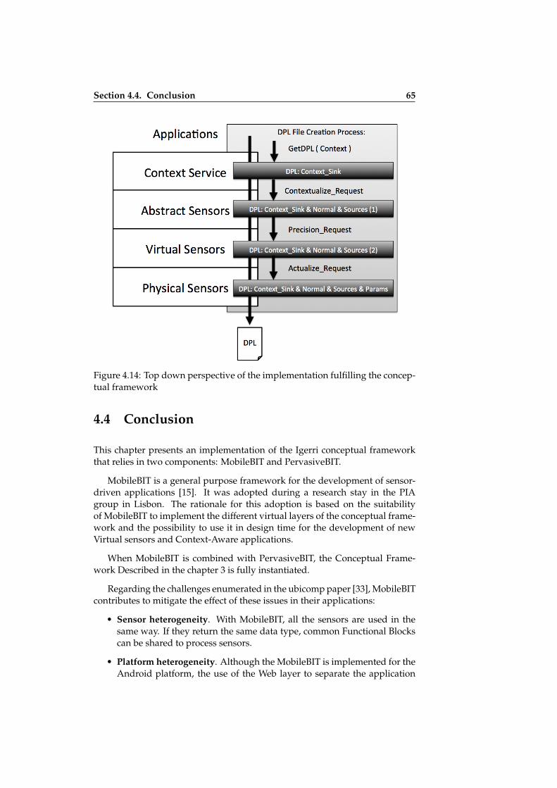
ii
ii
ii
ii
Section 4.4. Conclusion 65
Figure 4.14: Top down perspective of the implementation fulfilling the concep-tual framework
4.4 Conclusion
This chapter presents an implementation of the Igerri conceptual frameworkthat relies in two components: MobileBIT and PervasiveBIT.
MobileBIT is a general purpose framework for the development of sensor-driven applications [15]. It was adopted during a research stay in the PIAgroup in Lisbon. The rationale for this adoption is based on the suitabilityof MobileBIT to implement the different virtual layers of the conceptual frame-work and the possibility to use it in design time for the development of newVirtual sensors and Context-Aware applications.
When MobileBIT is combined with PervasiveBIT, the Conceptual Frame-work Described in the chapter 3 is fully instantiated.
Regarding the challenges enumerated in the ubicomp paper [33], MobileBITcontributes to mitigate the effect of these issues in their applications:
• Sensor heterogeneity. With MobileBIT, all the sensors are used in thesame way. If they return the same data type, common Functional Blockscan be shared to process sensors.
• Platform heterogeneity. Although the MobileBIT is implemented for theAndroid platform, the use of the Web layer to separate the application

ii
ii
ii
ii
66 Chapter 4. Implementation of the Conceptual Framework
from the sensor abstraction engine makes it possible to run the same con-text aware applications on new platforms such as iOS or Windows Phoneif they have a version of MobileBIT implemented.
• Encapsulation for complex data processing. Normal Blocks providea quick way to implement complex data processing. Some generic fil-ters can be applied by means other than Normal Blocks before and afterthe processing, thereby easing the programming task. Heavy processingtasks can use an external server to obtain faster results without affectingthe performance of the mobile device.
• Bad performance. A number of design tips to improve the performanceof the Functional Blocks have been described. If the blocks are well pro-grammed, the developer does not need to know inner details of the An-droid system to improve the performance of their applications.
Regarding the original motivation for this thesis, the lack of an adaptabil-ity mechanism in the Egoki system (as stated in Chaper 1), applications basedon this implementation have the possibility of improving a Egoki-based Ubiq-uitous System. Due to the possibility of loading web applications in the Weblayer and to updating them using the sensor abstraction layer described in thischapter, minor updates should be required to improve the accessibility and in-teractions of Egoki user interfaces. In this way, this approach addresses thefirst approach to this thesis, described in the MOBACC workshop [32].
The design of PervasiveBIT is similar to Egoki: it relies on a Knowledgebase and uses middleware for automatic discovery in the network. Althoughworking for different purposes, both (Egoki and Igerri) can share the sameinfrastructure (a server connected in the network), and also share informationbetween both Knowledge bases EGONTO and SENSONTO.

ii
ii
ii
ii
Chapter 5
Evaluation
In this chapter, an evaluation of the Igerri framework is carried out usingrepresentative Context-Aware applications. These applications are basedon the concept of Animatronic Biofeedback and examine the movementsof the arm to move a mobile robotic platform. The evaluation was carriedout with a total of 29 participants obtaining good results in terms of theusability of the applications.
5.1 Introduction
Usability testing comprises a set of practices with which to test the user inter-faces of prototypes with representative users attempting representative tasks [51].With usability testing we can check an applications’ functionality, asses theuser’s experience and identify specific problems in applications [26]. In Chap-ter 1, we enumerated a series of questions and the hypothesis concerning theusability for Context-Aware applications developed following the Igerri ap-proach. The results of the usability testing are essential to obtain an answer tothese research questions:
Research Question 1. Can Igerri produce functional and usable ap-plications with the mobile Context-Aware framework?
Research Question 2. Are the users able to control sensor enhancedapplications following the Igerri approach?
Research Question 3. Do the users perceive sensor enhanced Igerriapplications as being appealing, engaging and/or of added value?
On the whole, these questions lead to the following hypothesis: The abstrac-tion and virtualization of sensors as presented in Igerri are valid techniques with whichto develop usable Context-Aware applications.
In the Context-Aware computing field, from a Human Computer Interac-tion perspective, researchers use prototypes and case studies to evaluate and
67

ii
ii
ii
ii
68 Chapter 5. Evaluation
test frameworks and systems. Usually a part of the whole system is tested,rather than the whole system [69]. The evaluation carried out for Igerri is fo-cused on the usability of a representative application. We wanted to obtainevidences whether the above mentioned hypothesis is valid or not from theresults of the evaluation (See Figure 5.1).
Figure 5.1: Evaluation approach followed for Igerri
The applications proposed in this chapter addresses two functionalities:
• The generation of context information from a developer perspective.The tested applications use information relevant to the developers ob-tained by means of sensors. This information helps to characterise thesituation of an entity, in this case the arm of the user. Thus this informa-tion can be considered context following Dey’s definition [24] mentionedin Chapter 2.
• The creation of virtual sensors. Physical sensors are involved in the cre-ation of high-level context information. In this case, the arm context isprocessed using a Virtual sensor defined in 5.3.
Besides these two functionalities the rest of the framework is also indirectlyinvolved in the evaluation.
To obtain evidence on this matter, representative applications developedwith MobileBIT, based on the Igerri framework, were tested using differentusability techniques.
5.1.1 Description of the Experimental Evaluation
For the experimental evaluation, quantitative and qualitative assessment wereconsidered. For quantitative evaluation, it was necessary to design and cre-ate representative tasks to obtain objective and measurable values. These taskswere designed to combine all the functionalities available in the application.Two types of parameters were studied: First, the task performance, representedby the number and type of errors (if any). To this end, the ability of the par-ticipant to finish the task or not is measured. The time performance is alsomeasured, providing a benchmark with which to compare participants and as-sign them with a reference value. This result can be used to determine if a userhad trouble or was unable to use the application properly.
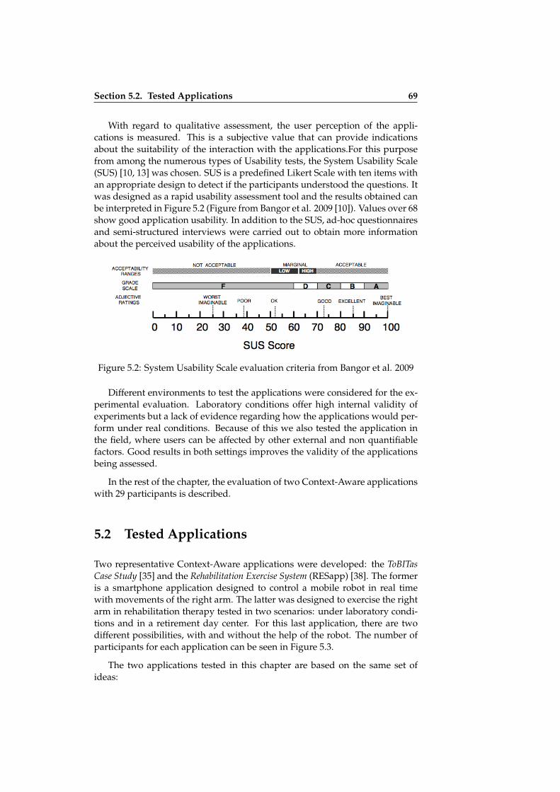
ii
ii
ii
ii
Section 5.2. Tested Applications 69
With regard to qualitative assessment, the user perception of the appli-cations is measured. This is a subjective value that can provide indicationsabout the suitability of the interaction with the applications.For this purposefrom among the numerous types of Usability tests, the System Usability Scale(SUS) [10, 13] was chosen. SUS is a predefined Likert Scale with ten items withan appropriate design to detect if the participants understood the questions. Itwas designed as a rapid usability assessment tool and the results obtained canbe interpreted in Figure 5.2 (Figure from Bangor et al. 2009 [10]). Values over 68show good application usability. In addition to the SUS, ad-hoc questionnairesand semi-structured interviews were carried out to obtain more informationabout the perceived usability of the applications.
Figure 5.2: System Usability Scale evaluation criteria from Bangor et al. 2009
Different environments to test the applications were considered for the ex-perimental evaluation. Laboratory conditions offer high internal validity ofexperiments but a lack of evidence regarding how the applications would per-form under real conditions. Because of this we also tested the application inthe field, where users can be affected by other external and non quantifiablefactors. Good results in both settings improves the validity of the applicationsbeing assessed.
In the rest of the chapter, the evaluation of two Context-Aware applicationswith 29 participants is described.
5.2 Tested Applications
Two representative Context-Aware applications were developed: the ToBITasCase Study [35] and the Rehabilitation Exercise System (RESapp) [38]. The formeris a smartphone application designed to control a mobile robot in real timewith movements of the right arm. The latter was designed to exercise the rightarm in rehabilitation therapy tested in two scenarios: under laboratory condi-tions and in a retirement day center. For this last application, there are twodifferent possibilities, with and without the help of the robot. The number ofparticipants for each application can be seen in Figure 5.3.
The two applications tested in this chapter are based on the same set ofideas:

ii
ii
ii
ii
70 Chapter 5. Evaluation
Figure 5.3: Summary of users for each application
• Firstly, the use of an Animatronic Biofeedback approach (informally de-fined as the use of pre-programmed actions in a robot that are triggered inresponse to certain changes detected in the users biomechanical or elec-trophysiological signals).
• Secondly, the use of the right arm monitorization using a BITalino sensorplatform as an input interface [73].
• Finally, performing remote control of a mobile robotic platform knownas Bot’n Roll [62].
A key element in biofeedback is the ability to measure how a given move-ment or exercise is being performed. The most common exercises involve ei-ther the musculoskeletal system, biomechanical activities, or a combination ofboth. We used the Electromyography (EMG) and Accelerometry (ACC) sen-sors to measure movements. EMG provides a direct measurement of the re-cruitment of one or several groups of muscles, while ACC can be used forbiomechanical assessment (e.g. range of motion, limb tilt, etc.).
Although these sensors can be used for a wide range of movements, inthe proposed applications, the perceived context information is focused on thecontraction of muscles and tilt movements of the right arm. The user mustwear a band with the BITalino attached to the wrist to acquire those signals.These experiments focus on muscle contraction of the Biceps and the Thenareminence and on the wrist tilt movement. The arrangement of the electrodesare shown in Figure 5.4. From left to right: EMG 1 (biceps), EMG 2 (thenar em-inence) and the board placement on the wrist with incorporated ACC sensor.
The application is notified regarding every new context information ac-quired and as a result it sends a command to move the robot as a biofeedbackresponse. In this way the Animatronic Biofeedback is achieved. The set of pro-grammed movements for the robot are the same for both applications: forward
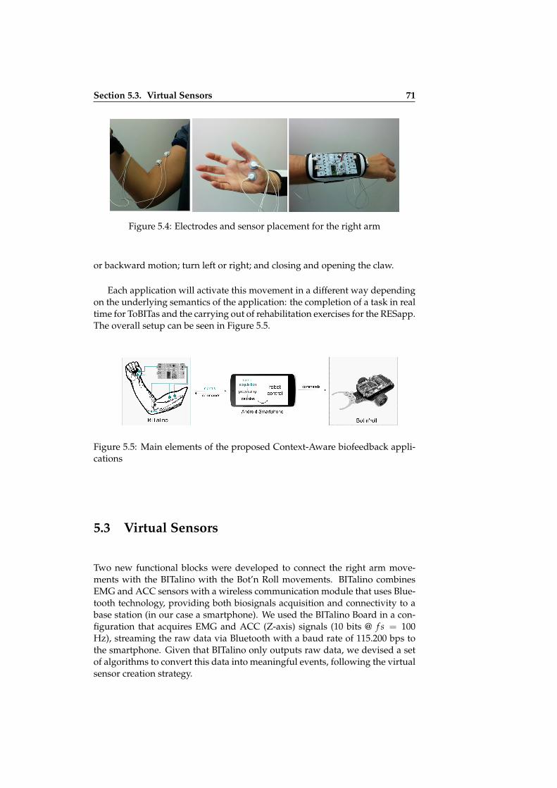
ii
ii
ii
ii
Section 5.3. Virtual Sensors 71
Figure 5.4: Electrodes and sensor placement for the right arm
or backward motion; turn left or right; and closing and opening the claw.
Each application will activate this movement in a different way dependingon the underlying semantics of the application: the completion of a task in realtime for ToBITas and the carrying out of rehabilitation exercises for the RESapp.The overall setup can be seen in Figure 5.5.
Figure 5.5: Main elements of the proposed Context-Aware biofeedback appli-cations
5.3 Virtual Sensors
Two new functional blocks were developed to connect the right arm move-ments with the BITalino with the Bot’n Roll movements. BITalino combinesEMG and ACC sensors with a wireless communication module that uses Blue-tooth technology, providing both biosignals acquisition and connectivity to abase station (in our case a smartphone). We used the BITalino Board in a con-figuration that acquires EMG and ACC (Z-axis) signals (10 bits @ f s = 100Hz), streaming the raw data via Bluetooth with a baud rate of 115.200 bps tothe smartphone. Given that BITalino only outputs raw data, we devised a setof algorithms to convert this data into meaningful events, following the virtualsensor creation strategy.

ii
ii
ii
ii
72 Chapter 5. Evaluation
5.3.1 Muscle Contraction Detection
For EMG data, we used an onset detection algorithm consisting of two stages,namely a processing block to filter the signal and compute the envelope of theEMG signal, and a decision rule block (see Fig. 5.6). The processing block usesa sliding window of M = 40 samples to perform a moving average filtering ofthe signal as described by Equation 5.1 x[n] is the input signal (EMG), s[n] isthe filtered signal, and M is the sliding average window size. For a samplingfrequency of 100 Hz, the −3 dB cut-off frequency is approximately 30 Hz andthe gain is 2 at 0 Hz. The phase shift is 20 ms (two samples):
Figure 5.6: Signal Processing for the EMG
s[n] =1M
M−1
∑j=0
x[n− j]. (5.1)
Afterwards, signal rectification is performed by subtracting the DC com-ponent s[n] and computing the absolute value of each point within the slidingwindow, as defined by Equation (5.2).
z[n] =
∣∣∣∣∣s[n]− 1M
M−1
∑j=0
s[n− j]
∣∣∣∣∣ . (5.2)
The processing stage finishes by computing the average value of the slidingwindow, as described in Equation 5.3 (where M = 40). Finally, we obtain aresultant value, y[n] for each M samples of the raw input signal. An example,biceps contractions, can be seen in Fig. 5.7.
y[n] =1M
M−1
∑j=0
z[n− j]. (5.3)
Finally, a simple decision rule is applied to y[n] to determine if there is amuscle contraction when y[n] > threshold. The threshold value is defined asa percentage of what is called the Maximum Voluntary Contraction (MVC). Inthe calibration stage, the user is asked to voluntarily contract each muscle beingmonitored in order to determine the maximum muscle activation amplitude hecan produce. An expert, for instance the therapist in the rehabilitation scenario,defines the threshold manually as a percentage of the MVC. The fact that thisis a relative value makes it insensitive to variable factors between exercisingsessions (e.g. skin moisture, different electrodes, different devices, etc.).

ii
ii
ii
ii
Section 5.3. Virtual Sensors 73
Figure 5.7: EMG signal used to evaluate the adopted algorithm. The algorithmfacilitates the onset detection
This functional Block is called Muscle contraction. The input is an EMG rawsignal from a muscle and returns "contracted" or "relaxed" values if a certainthreshold is passed or not. The block has the following Normal Block structure:
1 "MuscleContraction:<label >":{2 "config":{3 "threshold":<number >4 },5 "in":{6 "1":<input_label >7 },8 "out":{9 "1":<output_label >
10 }11 }
Listing 5.1: DPL for muscle contraction
5.3.2 Limb Tilt and Motion Detection
The strategy used for ACC data processing follows the same approach. How-ever, the processing stage consists only of a low-pass filter implemented witha moving average filter, as described by Equation 5.1. Similarly to the EMGapproach, the ACC decision rule is applied to determine the ACC position ineach instant and compare it with a threshold value interval. The thresholds forthe ACC were calculated by the analyzing the values for the processed dataand mapping them with the limb positions. As an example of limb tilt, Figure5.8 shows three positions of an accelerometer attached to the wrist.
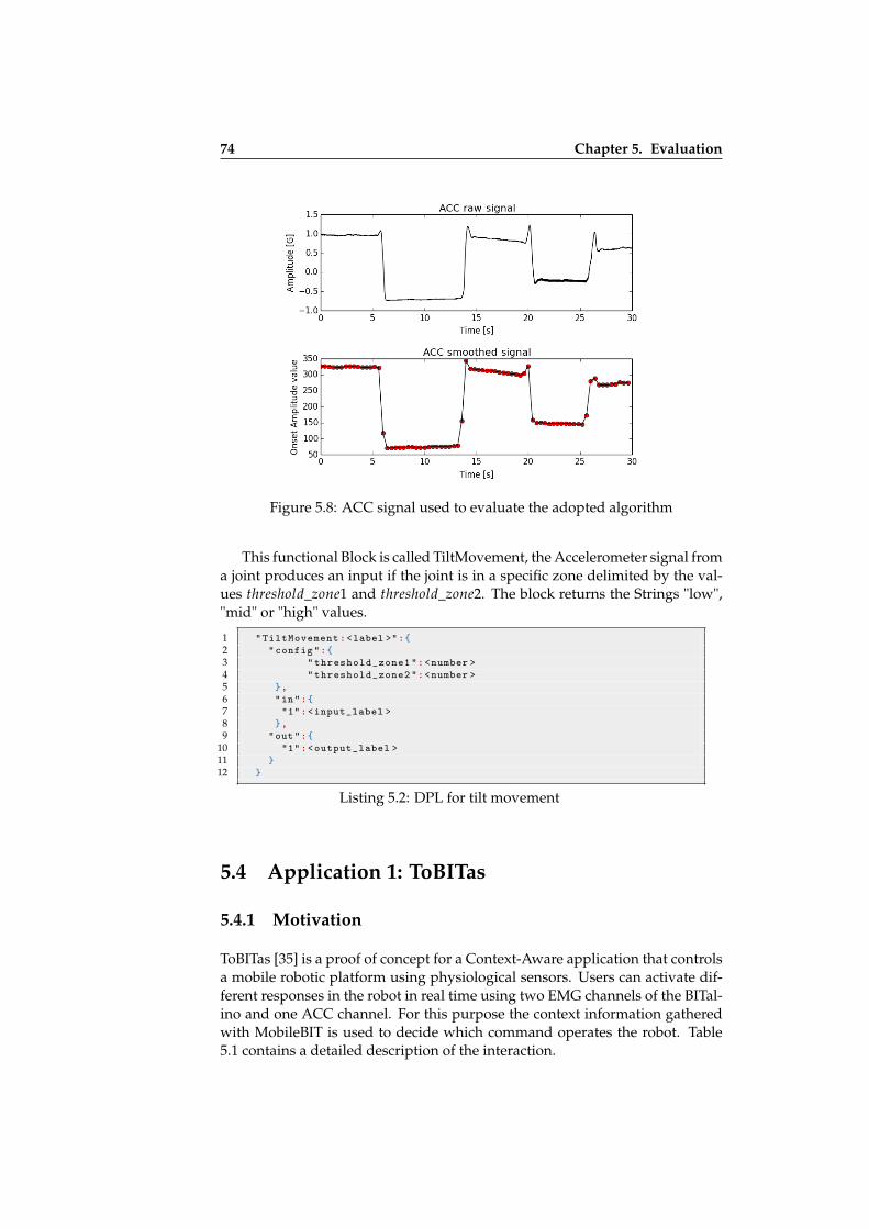
ii
ii
ii
ii
74 Chapter 5. Evaluation
Figure 5.8: ACC signal used to evaluate the adopted algorithm
This functional Block is called TiltMovement, the Accelerometer signal froma joint produces an input if the joint is in a specific zone delimited by the val-ues threshold_zone1 and threshold_zone2. The block returns the Strings "low","mid" or "high" values.
1 "TiltMovement:<label >":{2 "config":{3 "threshold_zone1":<number >4 "threshold_zone2":<number >5 },6 "in":{7 "1":<input_label >8 },9 "out":{
10 "1":<output_label >11 }12 }
Listing 5.2: DPL for tilt movement
5.4 Application 1: ToBITas
5.4.1 Motivation
ToBITas [35] is a proof of concept for a Context-Aware application that controlsa mobile robotic platform using physiological sensors. Users can activate dif-ferent responses in the robot in real time using two EMG channels of the BITal-ino and one ACC channel. For this purpose the context information gatheredwith MobileBIT is used to decide which command operates the robot. Table5.1 contains a detailed description of the interaction.

ii
ii
ii
ii
Section 5.4. Application 1: ToBITas 75
Table 5.1: Relationship between the acquired signals, context information andsystem behaviour
Signal User Action Context Information Robot Command
EMG_1 The user folds his arm Action_detected: Right_arm_folded Move ForwardEMG_2 The user closes his hand Action_detected: Hand_Closed Open/Close the Claw
ACCTilt the wrist to the left Position_detected: Wrist_up Move RightTilt the wrist to the right Position_detected: Wrist_down Move LeftWrist in central position Position_detected: Wrist_side Don’t Move
5.4.2 Methods
The ToBITas Case Study was created to test the adaptation of the user to physio-logically-enhanced sensor input methods. In addition to this, user satisfactionwas also measured. For that purpose we performed an exploratory study eval-uating the interaction of the participants with ToBITas completing a simplerobot control task. We had two research questions:
• Are the users able to control our system?
• Do users feel comfortable with this kind of control?
For the former, the times to complete the task were measured for each par-ticipant in order to compare the learning effect between participant groups. Forthe latter, the participants were asked to complete the System Usability Scalequestionnaire to obtain insights into the user satisfaction.
Participants
We recruited thirteen volunteers (four females) from the surrounding researchlaboratories of the IST-UL university campus. The participants ranged from21 to 39 years old and all of them were right-handed. They were divided inthree groups by their level of expertise and equipped with similar devices andapplications:
• Group A (Novices). For seven participants for whom it was the first timethat they had tried this kind of user interface.
• Group B (Experienced). Four participants who had reported to some pre-vious experience controlling similar systems but for whom it was the firsttime they had used this system.
• Group C (Experts). Two participants who were involved in the designand development of the system. They were included in order to serve asa performance reference.
Apparatus
• A BITalino board was used for the EMG and ACC data acquisition.

ii
ii
ii
ii
76 Chapter 5. Evaluation
• Bot’n Roll One was the mobile robotic platform.
• The smartphone was an LG Optimus F5 with Android 4.1.2, a Dual-Core1.2GHz processor and 1GB RAM.
Procedure
To start, the demographic background of each user was noted. Subsequently,the BITalino device was set up and the electrodes were placed as mentioned inFigure 5.4. Afterwards, the calibration phase was carried out with the help ofthe researchers. Then, each user was asked to carry out the following routine:
1. Move the robot one meter to approach the cylindrical object
2. Grab the cylindrical object with the claw
3. Move the robot one meter to the target
4. Release the cylindrical object at the given position
The tasks is depicted in Figure 5.9. In addition, a demo video of the task canbe seen in http://sipt07.si.ehu.es/bgamecho/ToBITas/Demo_video.mp4
Figure 5.9: Experimental set-up and task description for the evaluation of To-BITas use case
Each participant performed the task three times. The performance wasrecorded on video and stored altogether with log data from the application. Fi-nally, participants of Groups A and B completed the SUS questionnaire, GroupC participants did not complete the SUS questionnaire to avoid a conflict ofinterests.
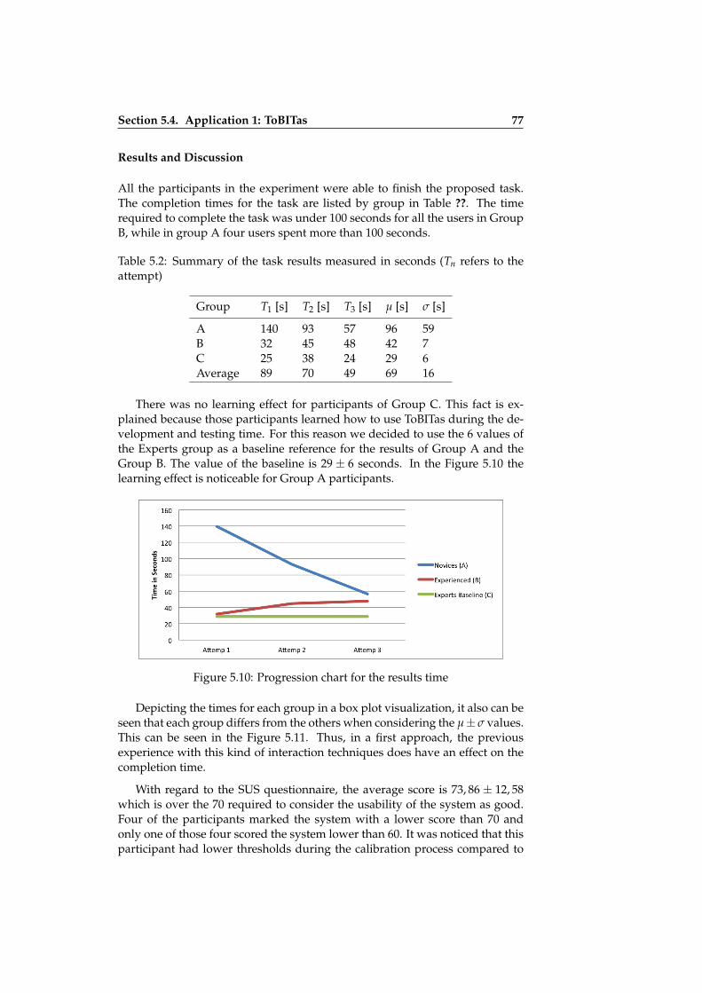
ii
ii
ii
ii
Section 5.4. Application 1: ToBITas 77
Results and Discussion
All the participants in the experiment were able to finish the proposed task.The completion times for the task are listed by group in Table ??. The timerequired to complete the task was under 100 seconds for all the users in GroupB, while in group A four users spent more than 100 seconds.
Table 5.2: Summary of the task results measured in seconds (Tn refers to theattempt)
Group T1 [s] T2 [s] T3 [s] µ [s] σ [s]
A 140 93 57 96 59B 32 45 48 42 7C 25 38 24 29 6Average 89 70 49 69 16
There was no learning effect for participants of Group C. This fact is ex-plained because those participants learned how to use ToBITas during the de-velopment and testing time. For this reason we decided to use the 6 values ofthe Experts group as a baseline reference for the results of Group A and theGroup B. The value of the baseline is 29 ± 6 seconds. In the Figure 5.10 thelearning effect is noticeable for Group A participants.
Figure 5.10: Progression chart for the results time
Depicting the times for each group in a box plot visualization, it also can beseen that each group differs from the others when considering the µ± σ values.This can be seen in the Figure 5.11. Thus, in a first approach, the previousexperience with this kind of interaction techniques does have an effect on thecompletion time.
With regard to the SUS questionnaire, the average score is 73, 86 ± 12, 58which is over the 70 required to consider the usability of the system as good.Four of the participants marked the system with a lower score than 70 andonly one of those four scored the system lower than 60. It was noticed that thisparticipant had lower thresholds during the calibration process compared to

ii
ii
ii
ii
78 Chapter 5. Evaluation
Figure 5.11: Box plot for the times in each phase
other participants, which made the system more sensitive to noise. Therefore,on some occasions, the processing algorithm did not follow the participant’sdemands and expectations. However, the bad result might be due to noisewithin the acquisition scenario, or bad electrode placement. Surprisingly, in thethird run all the participants from both groups A and B spend approximatelyaround 55 seconds to perform the task. This suggest that after two trials userGroup A obtained a similar level of experience as user Group B.
On the other hand, some flaws were detected in the system that must be ad-dressed in future versions. For instance, it was reported that the tilt movementof the wrist associated to a right turn by the robot sometimes also activated thethresholds for the biceps and the thenar eminence muscles. This unintendedmovement was noticed by some of the participants who started to move theirarm more accurately. Others instead followed a strategy of "only turning to theleft" to avoid the undesired movement. New DSP algorithms combining threesignals (EMG1, EMG2, ACC) should be tested to fix this issue.
The results showed that users were able to understand and quickly learnhow to use our approach. ToBITas is a functional and usable Context-Awareapplication, proving that Igerri is able to provide valid Context-Aware appli-cations. The input method based on EMG and ACC sensors performed well forthe control of a mobile robot. Moreover, since the users were able to shortenthe experience time in each repetition, this seems to indicate that the users wereable to adapt themselves to the system quickly.

ii
ii
ii
ii
Section 5.5. Application 2: Rehabilitation Exercise System (RESapp) 79
5.5 Application 2: Rehabilitation Exercise System(RESapp)
The second application developed with the Igerri Framework RESapp [38] wasdesigned as a tool for rehabilitation therapy.
5.5.1 Motivation
Every year, a great number of people worldwide undergo physical rehabil-itation due to work related injuries [1], disability [2], and other conditions.Within the portfolio of tools that therapists currently have at their disposal,biofeedback has become particularly popular [40, 71], with clinical evidenceshowing that it is an engaging technique with multiple benefits for the pa-tient [12, 40, 47, 71].
As a way of improving the effectiveness of treatments, the extension of therehabilitation process to people’s homes with biofeedback exercises has beenproposed. These exercises would be designated by the therapist to be per-formed autonomously by the patient at home between sessions at the clinic [20,59, 60].
A major advantage of biofeedback is the possibility of deriving objectiveperformance indicators from direct physiological measurements in real time,and using them for live progress monitoring and guidance of the rehabilitationexercises to maximize the potential outcomes. A critical aspect in any biofeed-back system are positive and negative reinforcement cues, provided to the pa-tient in real time when a given exercise is being executed. These are used as away of confirming whether the goals set by the therapist are being met or not.
As recently argued by Chandra, Oakley and Silva [16], physical rehabil-itation at home using biofeedback is hindered by multiple factors, user en-gagement being the most important. Positive and negative reinforcement cuesprovided to the user during the exercises play a major role in user engagement.
Reinforcement cues used in biofeedback are generally visual, acoustic,and/or haptic signals delivered through a computer or mobile device actingas the interface with the patient. However, aspects such as screen size, inputinterfaces, lack of technological proficiency, reduced sight or hearing abilities,and other factors associated with the more traditional feedback methods canpose difficulties to specific user groups (such as elderly patients), ultimatelyleading to poor compliance in home exercises.
5.5.2 Proposed Approach
The animatronic biofeedback presented in ToBITas was adapted for a telereha-bilitation scenario with elderly users. The main change is the substitution from

ii
ii
ii
ii
80 Chapter 5. Evaluation
the continuous control mode to a step by step one, which proved to be moreappropriate for the performance of rehabilitation exercises.
In this second approach, only one movement at a time is allowed, and con-sequently the mobile application is waiting to finish the exercise to allow thenext movement. In this way we can overcome the problems regarding the mul-tiple activation of the different movements mentioned in the discussion of theprevious evaluation. Another difference with the previous experiment is thatthe EMG signal from the thenar eminence muscle was eliminated because itwas not a good choice for the type of exercises envisioned. Both applicationsuse the BITalino board for the acquisition of EMG and ACC.
The system recognizes two kinds of exercises performed with the right armand triggers different actions in the animatronic:
• Activating the biceps (e.g. folding the arm) for T seconds moves the robotforward for a distance of 40 cm.
• Tilting the wrist to the left or right for T seconds animates the robot toturn in the same direction for 90 degrees.
Ideally physiotherapists define routines which chain these exercises. Usu-ally the same exercise would be repeated a number of times. If the exercise isinterrupted, the system will activate the negative biofeedback cue. After thenegative biofeedback cue, the user must always repeat the last exercise again.We consider the following events as interruptions:
• For muscles: When the contraction value is under the threshold set up inthe calibration phase.
• For tilt positions: When the value of the accelerometer is outside the re-gion defined for an exercise.
The application was developed following a life cycle of two iterations. Ad-ditionally, in every iteration, the animatronic biofeedback was compared to analternative method. The objective was to ascertain if the animatronic biofeed-back presented advantages over other feedback methods.
• Iteration 1 was a pilot test under laboratory conditions with 5 users. Theanimatronic biofeedback application was compared to human user feed-back.
• Iteration 2 was improved with the feedback from the first iteration. Theanimatronic biofeedback positive and negative cues were changed. Thenit was tested in an association of retired people with 11 participants. Forthis iteration the animatronic biofeedback was compared with a visualbiofeedback.
In order to design the exercises, both biceps contraction and wrist move-ments were designed. They were chosen following the previous experience ofthe researchers of IST-UL who have experience in this area. It must be clearlystated that no medical benefits can be claimed using this evaluation, since ithas been designed to check the usability of the approach rather than check if
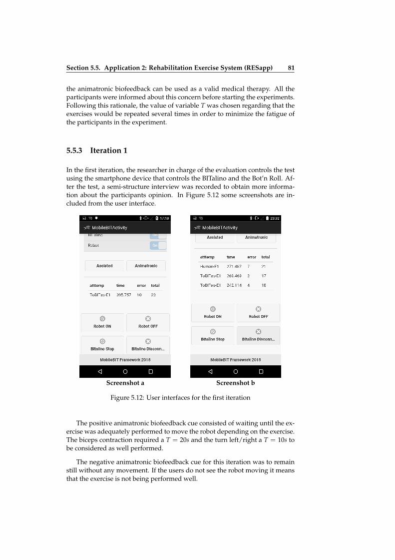
ii
ii
ii
ii
Section 5.5. Application 2: Rehabilitation Exercise System (RESapp) 81
the animatronic biofeedback can be used as a valid medical therapy. All theparticipants were informed about this concern before starting the experiments.Following this rationale, the value of variable T was chosen regarding that theexercises would be repeated several times in order to minimize the fatigue ofthe participants in the experiment.
5.5.3 Iteration 1
In the first iteration, the researcher in charge of the evaluation controls the testusing the smartphone device that controls the BITalino and the Bot’n Roll. Af-ter the test, a semi-structure interview was recorded to obtain more informa-tion about the participants opinion. In Figure 5.12 some screenshots are in-cluded from the user interface.
Screenshot a Screenshot b
Figure 5.12: User interfaces for the first iteration
The positive animatronic biofeedback cue consisted of waiting until the ex-ercise was adequately performed to move the robot depending on the exercise.The biceps contraction required a T = 20s and the turn left/right a T = 10s tobe considered as well performed.
The negative animatronic biofeedback cue for this iteration was to remainstill without any movement. If the users do not see the robot moving it meansthat the exercise is not being performed well.

ii
ii
ii
ii
82 Chapter 5. Evaluation
Due to the fact that the goal for the first iteration was to obtain a prelim-inary version for the animatronic biofeedback, the results are summarized inthe following lines. The evaluation of the second iteration is fully described inthe Section 5.5.5.
Pilot Testing Results
The pilot testing was conducted with 5 participants (2 males) from an agegroup of 70± 4 years old. All of them were able to complete a representativeroutine of exercises. The average completion time was 296.1± 75.6 seconds forthe user feedback and 322.9± 89.55 seconds for the animatronic biofeedback.Regarding the number of errors, for the user feedback an average of 8± 6 errorswere obtained and on the other hand an average of 8± 7 errors were obtained.The SUS evaluation obtained and average value of 84 ± 4.64 meant that theusability of the applications was perceived as excellent.
Discussion and Conclusion
The pilot testing was useful to understand that the animatronic feedback couldbe more effective as far as the positive and negative cues were concerned. Aseries of conclusions and lessons learnt were obtained from this pilot evalua-tion:
• Comparing the Human feedback with the animatronic biofeedback ispointless. Generally, human feedback is expected to be more effectiveand understandable than other biofeedback methods.
• The time required to perform the exercises should be lower. A period of20 seconds for the biceps contraction is not adequate for this evaluationbecause it is quite hard for the users to maintain since fatigue and tired-ness is accumulated during the evaluation session. Considering that thisis not a real physiotherapy session the tiredness could be confoundedwith poor usability of the system.
• Animatronic Positive and negative reinforcement cues could be misun-derstood. On the one hand, positive biofeedback should be representedas a continuous movement of the robot. On the other hand, negativebiofeedback should not be merely that the robot remains still withoutmoving the robot.
Regarding the use of Igerri and the appropriateness of the user interfacesand interaction methods, it shows that the developed applications are usableand functional for the 5 users.

ii
ii
ii
ii
Section 5.5. Application 2: Rehabilitation Exercise System (RESapp) 83
5.5.4 Iteration 2
For the second iteration, the researcher carrying out the experiment, controlsremotely the activation of the exercise routine and monitors how it is working(see Figure 5.13). We call this user interface the Therapist panel. For this iter-ation, two devices were used, one for the visual biofeedback test and anotherone for the animatronic biofeedback test.
Figure 5.13: Web interface to start and control the experiment from a remoteDevice
Visual Biofeedback Application
The Visual biofeedback application developed using MobileBIT relies on theindications in the screen of the mobile device to perform the exercises (see Fig-ure 5.14). The screen showed a counter from 30 to 0. Visual biofeedback wasimplemented in the following way:
• Positive Visual cue: while the exercise was being performed well thecounter counts down. Every 400ms the counter decreases by 1. Whenever

ii
ii
ii
ii
84 Chapter 5. Evaluation
Screenshot a Screenshot b
Figure 5.14: User interfaces for the Visual Biofeedback application
the countdown reached 0 the exercise was considered to be successfullyperformed and the next exercise was prompted on the screen.
• Negative Visual cue: when an error was detected the counter resets to 30.
Animatronic Biofeedback for Rehabilitation
Using the Bot’n Roll features we programmed animatronic feedback actionsthat can be triggered as positive reinforcement cues when the user is correctlyperforming a given exercise. These movements can be to move forward forsome centimeters, or to turn to the right or to the left for 90º. The negativereinforcement cue is common to all exercises, and is expressed by the robotgoing backwards to the place it was before the last movement. If the robotremains still without moving it could mean different things:
• After positive feedback: the current exercise has been performed well.
• After negative biofeedback: the last exercise can be tried again.
• In the remaining cases: the current movement has not been correctly per-formed yet.
ii
ii
ii
ii
Section 5.5. Application 2: Rehabilitation Exercise System (RESapp) 85
5.5.5 Methods
For the evaluation of the RESapp scenarios, a comparative approach has beenadopted between the two biofeedback methods:
• Method A: Visual Biofeedback application.
• Method B: Animatronic Biofeedback application.
We want to know what the differences are for both of methods regardingthe time to complete the rehabilitation routines and the number of errors per-forming the exercises. We also want to study how the users perceive the us-ability of these applications and if they are functional and usable. We believethat this Context-Aware animatronic biofeedback perspective can greatly con-tribute to further enhance the set of tools available for therapists, especially inwith regard to methods for increasing compliance to home exercises in elderlypatients. Therefore the evaluation of RESapp scenarios were performed withretired people from 64 to 80 years.
Participants
11 volunteers (4 males) were recruited from an association of retired people.The participants age ranged from 64 to 78 years (73.2± 4, 4). Informed consentwas obtained from all individual participants included in the study.
Apparatus
• A BITalino board was used for the EMG and ACC data acquisition.
• Bot’n Roll One was the mobile robotic platform.
• For the Method A a Rikomagic MK902II mini-PC with Android 4.4 wasused connected to a 14 inch monitor.
• For Method B, a Nexus 5 smartphone with Android 5.0.1
Procedure
First, demographical data were gathered by means of a short questionnaire.After that, the participants were helped to adjust the BITalino to the right arm.Subsequently a calibration phase was carried out to find out the MVCs andto define the activation threshold. The EMG electrodes were placed over themuscle fibres of the biceps, at a distance of approximately 2 cm. The referenceelectrode is placed on a bone area on the elbow. The ACC sensor is on theBITalino board, which is placed on the right wrist of the user, as shown in Fig.5.4.
In our experimental evaluation we will consider an activation thresholdaround 20% of the MVC, this threshold should be changed to a lower one if the
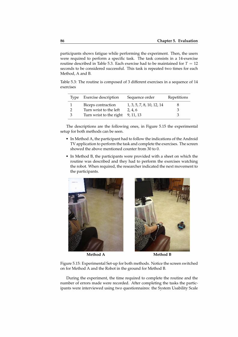
ii
ii
ii
ii
86 Chapter 5. Evaluation
participants shows fatigue while performing the experiment. Then, the userswere required to perform a specific task. The task consists in a 14-exerciseroutine described in Table 5.3. Each exercise had to be maintained for T = 12seconds to be considered successful. This task is repeated two times for eachMethod, A and B.
Table 5.3: The routine is composed of 3 different exercises in a sequence of 14exercises
Type Exercise description Sequence order Repetitions
1 Biceps contraction 1, 3, 5, 7, 8, 10, 12, 14 82 Turn wrist to the left 2, 4, 6 33 Turn wrist to the right 9, 11, 13 3
The descriptions are the following ones, in Figure 5.15 the experimentalsetup for both methods can be seen.
• In Method A, the participant had to follow the indications of the AndroidTV application to perform the task and complete the exercises. The screenshowed the above mentioned counter from 30 to 0.
• In Method B, the participants were provided with a sheet on which theroutine was described and they had to perform the exercises watchingthe robot. When required, the researcher indicated the next movement tothe participants.
Method A Method B
Figure 5.15: Experimental Set-up for both methods. Notice the screen switchedon for Method A and the Robot in the ground for Method B.
During the experiment, the time required to complete the routine and thenumber of errors made were recorded. After completing the tasks the partic-ipants were interviewed using two questionnaires: the System Usability Scale
ii
ii
ii
ii
Section 5.5. Application 2: Rehabilitation Exercise System (RESapp) 87
(SUS) [13] and the preferences questionnaire described in Table 5.4. The ques-tionnaire was filled in by a research assistant to avoid misunderstandings ofquestions and likert scales. After finishing the experiment every participantwas rewarded with a ticket for a meal in the restaurant of the association.
Table 5.4: The second questionnaire is an 8 items likert scale with 7 answeroptions (1 totally disagree and 7 totally agree). Three categories are evaluated:User Satisfaction (US), User Awareness (UA) and the Location to apply thesystem (Loc).
Item Category Factor Statement
1 US Lack of difficulty I’m satisfied with the ease with which I completed the task.2 US Perceived time to I’m satisfied with the time I spent to complete the task.
complete the task3 US Comfortability I’ve felt comfortable using the system.4 US Amusement I’ve enjoyed using this system.5 UA Biceps movements I was aware that the biceps contraction exercise performed well.6 UA Wrist movements I was aware that the wrist tilt exercise performed well.7 Loc Rehab. center I would like to use this system in a rehabilitation center.8 Loc Home I would like to use this system at home.
Design
The experiment followed a within-subject design. Biofeedback Method con-dition was counterbalanced using a Latin square. For the same routine twobiofeedback Methods were tested, visual biofeedback and animatronic biofeed-back, and two attempts are performed to mitigate the learning effect. The rou-tine was composed of three different types of exercises: 8 biceps contraction,3 right wrist movements and 3 left wrist movements. Aside from calibration,the amount of expected entry was 11 participants× 2 Methods× 2 attempts×14 exercises/attempt = 616 exercises (352 biceps, 132 left, 132 right). For eachroutine, a minimum time of 14 exercises/routine × 12 seconds/exercise = 168seconds/routine are expected.
Results and Discussion
One of the volunteers did not finish the experiment because she could notmaintain the required biceps contraction for T = 12 seconds. Since that partic-ipant did not complete the routine, the final questionnaires were not filled in.The rest of the participants (N = 10) successfully completed the experiment.
Concerning the perceived usability of the system, the obtained SUS scoreswere 88.5± 7.2. Therefore, we can conclude that participants considered oursystem to be usable. Regarding the required time to finish all the exercises andthe error rate, we found that the results were similar for both Methods (seeTable 5.6 and Table 5.7).
With reference to the learning effect, in the second attempt, the time de-creased by 11 seconds (4%) for Method A and 25 seconds (8%) for Method B.
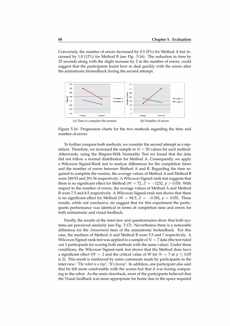
ii
ii
ii
ii
88 Chapter 5. Evaluation
Conversely, the number of errors decreased by 0.5 (5%) for Method A but in-creased by 1.8 (12%) for Method B (see Fig. 5.16). The reduction in time by25 seconds along with the slight increase by 2 in the number of errors, couldsuggest that the participants learnt how to deal quickly with the errors afterthe animatronic biofeedback during the second attempt.
(a) Time to complete the routine (b) Number of errors
Figure 5.16: Progression charts for the two methods regarding the time andnumber of errors
To further compare both methods, we consider the second attempt as a rep-etition. Therefore, we increased the sample to N = 20 values for each method.Afterwards, using the Shapiro-Wilk Normality Test we found that the datadid not follow a normal distribution for Method A. Consequently we applya Wilcoxon Signed-Rank test to analyse differences for the completion timesand the number of errors between Method A and B. Regarding the time re-quired to complete the routine, the average values of Method A and Method Bwere 249.93 and 291.56 respectively. A Wilcoxon Signed-rank test suggests thatthere is no significant effect for Method (W = 72, Z = −1232, p > 0.05). Withrespect to the number of errors, the average values of Method A and MethodB were 7.5 and 8.5 respectively. A Wilcoxon Signed-rank test shows that thereis no significant effect for Method (W = 94.5, Z = −0.392, p > 0.05). Theseresults, while not conclusive, do suggest that for this experiment the partic-ipants performance was identical in terms of completion time and errors forboth animatronic and visual feedback.
Finally, the results of the interview and questionnaires show that both sys-tems are perceived similarly (see Fig. 5.17). Nevertheless there is a noticeabledifference for the Amusement item of the animatronic biofeedback. For thiscase, the medians of Method A and Method B were 5.5 and 7 respectively. AWilcoxon Signed-rank test was applied to a sample of N = 7 data (the test ruledout 3 participants for scoring both methods with the same value). Under theseconditions, the Wilcoxon Signed-rank test shows that the Method does havea significant effect (W = 2 and the critical value of W for N = 7 at p ≤ 0.05is 2). This result is reinforced by some comments made by participants in theinterview: "The robot is a toy", "It’s funny". In addition, one participant also saidthat he felt more comfortable with the screen but that it was boring compar-ing to the robot. As the main drawback, most of the participants believed thatthe Visual feedback was more appropriate for home due to the space required

ii
ii
ii
ii
Section 5.6. Conclusion of the Usability Testing 89
for the movements of the robot. A viable solution for this concern can be theuse of a different robot instead of the Bot’n Roll. For instance, Rodriguez et al.2014 [63] propose the use of NAO humanoid robots to mimic the movementsof a human operator. This solution is more efficient because it does not needmore space than the required by the robot.
Figure 5.17: Mean values obtained for the results of the second questionnaire(see Table5.4)
5.6 Conclusion of the Usability Testing
This chapter describes a series of experiments for two context aware applica-tions developed using the Igerri conceptual framework and their implemen-tation. Quantitative and qualitative results were obtained and overall, the ap-plications were revealed to be fully functional and usable by the participantsduring the experiments.
Regarding the task performance and the errors, on the whole 27 of 29 par-ticipants finished the evaluation without problems. From a total of 13 partic-ipants, only one reported problems using ToBITas and another one had prob-lems using RESapp. In both cases, the thresholds were very low and this madeit impossible to use the applications. This means that the functional blocksdescribed in section 5.3 were valid for 93% of the participants.
With regard to the task completion time using ToBITas, novice users wereable to reduce the completion time of the proposed task over three attempts.With regard to the RESapp, despite the fact that a comparative study was con-ducted, both scenarios were developed with MobileBIT and they obtained asimilar completion time and error rate which indicate that the addition of anew element in the MobileBIT such as the robot did not lower usability.
With regard to the qualitative evaluation the SUS obtained acceptable re-sults as can be seen in Table 5.5. The SUS questionnaire was carried out by 26participants.

ii
ii
ii
ii
90 Chapter 5. Evaluation
Table 5.5: A summary of SUS evaluation results
Application Evaluation Participants Age Environment SUS Value
ToBITas Continuous control 11 20-40 Lab conditions 73, 86± 12, 58RESapp Step by Step Pilot 5 64 - 80 Lab conditions 84± 4.64RESapp Step by Step Final 10 64 - 80 In the field 88.5± 7.2
Overall, the evaluation shows good results and personal interviews andquestionnaires reported that the participants very quickly understood the con-cepts regarding the proposed control mode. It seems that the approach fol-lowed in this thesis produce:
• Functional Applications: All the functionalities tested regarding withsensors worked for 93% of the participants.
• Usable Applications: Participants graded ToBITas application with goodusability and RESapp with excelent usability.
• Appealing Applications: Participants of RESapp application experimentreported high values for different categories regarding user satisfactionand awareness of using the rehabilitation application.
This way research questions stated at the beginning of the chapter are an-swered. With regard to the hypothesis, we conclude that the implementation ofthe Conceptual Framework tested in this chapter is adequate to produce usableContext-Aware applications.
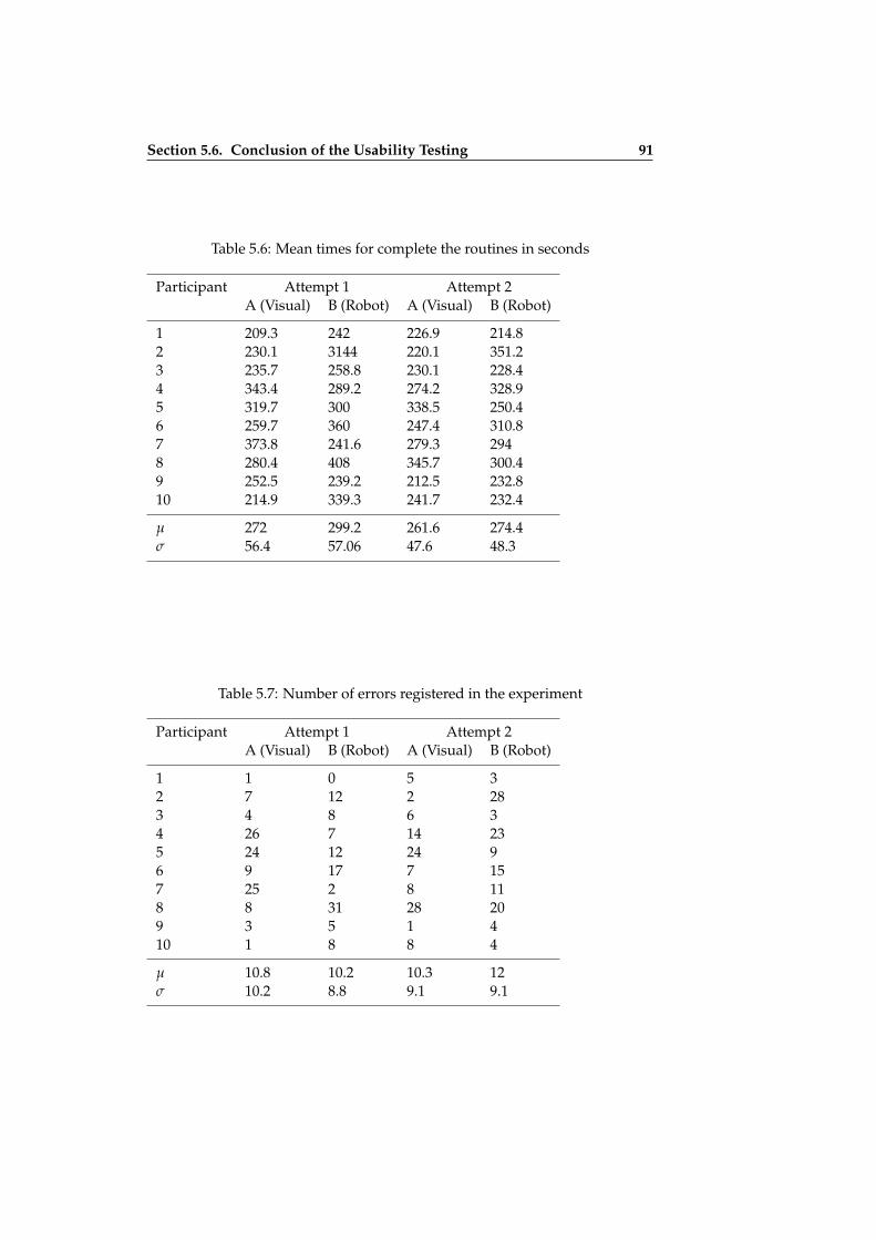
ii
ii
ii
ii
Section 5.6. Conclusion of the Usability Testing 91
Table 5.6: Mean times for complete the routines in seconds
Participant Attempt 1 Attempt 2A (Visual) B (Robot) A (Visual) B (Robot)
1 209.3 242 226.9 214.82 230.1 3144 220.1 351.23 235.7 258.8 230.1 228.44 343.4 289.2 274.2 328.95 319.7 300 338.5 250.46 259.7 360 247.4 310.87 373.8 241.6 279.3 2948 280.4 408 345.7 300.49 252.5 239.2 212.5 232.810 214.9 339.3 241.7 232.4
µ 272 299.2 261.6 274.4σ 56.4 57.06 47.6 48.3
Table 5.7: Number of errors registered in the experiment
Participant Attempt 1 Attempt 2A (Visual) B (Robot) A (Visual) B (Robot)
1 1 0 5 32 7 12 2 283 4 8 6 34 26 7 14 235 24 12 24 96 9 17 7 157 25 2 8 118 8 31 28 209 3 5 1 410 1 8 8 4
µ 10.8 10.2 10.3 12σ 10.2 8.8 9.1 9.1

ii
ii
ii
ii

ii
ii
ii
ii
Chapter 6
Conclusion & Future Work
In this chapter, the results obtained in this thesis are summarized and dis-cussed. The contributions to sensor abstraction and virtualization in thefield of mobile Context-Aware computing are highlighted. Finally, futurelines of research are presented.
6.1 Conclusion
This PhD presents Igerri, a conceptual framework for sensor abstraction andvirtualization. This framework is composed of a set of layers with differentlevels of abstraction. From a bottom up perspective, context information istransformed from raw data into context information of a higher level of ab-straction. This is achieved thanks to virtual and abstract sensors. This concep-tual framework was designed with the goal of facilitating the design of usablecontext aware applications for developers. In addition to this, the frameworklayers were designed to conceal from developers the difficulties of designingapplications for mobile Context-Aware computing.
The implementation shares concepts with the Igerri framework and facil-itates the creation of Context-Aware applications. To test our hypothesis, theconceptual framework was instantiated in two components named, MobileBITand PervasiveBIT. These software components were implemented for a mobileplatform and used an external server to achieve seamless integration across thedevices of the ubiquitous system. Igerri can be implemented in many ways,and it was decided to follow this approach because it provides enough mech-anisms to deal with the objective of the framework, the sensor abstraction andvirtualization.
Two sensor enhanced applications were developed for the evaluation ofthe resulting implementation. Both use external sensors in a wearable plat-form to test the generation of context, the abstraction and the virtualization ofsensors, in terms of perceived usability. The use of usability testing techniques
93

ii
ii
ii
ii
94 Chapter 6. Conclusion & Future Work
provides not only a way to measure the performance of the applications (badperformance leads to bad usability) but also show whether the applications areappealing or not for the users. A set of experiments were conducted with 29participants producing good results.
The evaluation for the framework was carried out testing the applications.However, the results obtained cannot be generalized to all the applications im-plemented following our framework. Anyway, the good results in the per-ceived usability of the applications show that Igerri was useful to create context-aware applications using the proposed implementation.
Consequently, the hypothesis presented in the research questions was sat-isfied (partially validated) by the implementation of Igerri and the proposedapplications: It is possible to create usable (1), controllable (2) and appealing(3) sensor-enhanced context-aware applications based on the mechanisms de-scribed by Igerri for sensor abstraction and virtualization. Although this factdoesn’t ensure to every application created with Igerri to be valid for the prop-erties (1 to 3), it evidences that these properties can be provided using Igerri. Inthe remaining sections, the relationship with Egoki, contributions, limitationson the followed approach, and possible future work are described.
6.2 Igerri as an Extension for Egoki
In the first chapter, it is suggested that the motivation for this research was anextension for the Egoki user interface generator. The original design of Egokiwas not intended for Context-Aware computing but for the generation of userinterfaces tailored to people with special needs using different adaptation tech-niques. Four problems or challenges were proposed to stretch Egoki regardingits limitations. How Igerri can be used to deal with these limitations is ex-plained below:
• With regard to the use of new input modalities, Igerri, as was probed inthe evaluation, can be used to gather information from sensors such asEMG or ACC to present a gesture based interaction. In the same way,other sensors can be taken into consideration to extend the input modal-ities available in Egoki.
• On the topic of the adaptability of Egoki user interfaces, the use of datafrom sensors (located in the environment and user devices) can improvethe existing adapting techniques. Igerri and its implementation provideaccess to the context information generated using sensors. This contextinformation is a valuable input for Egoki in order to generate adapteduser interfaces available through Igerri.
• In relation to proactive applications and the interaction without the useof graphical user interfaces, ToBITas is a good example of the capabilitiesof Igerri. It is possible to use Igerri-based applications to deal seamlessly

ii
ii
ii
ii
Section 6.3. Contributions 95
with different devices (i.e. robots, wearables, mobile devices), and allowthe user to control them without directly manipulating the mobile device.
• Concerning the use of mobile applications instead of web applications,the proposed implementation of Igerri is based on a Hybrid applicationapproach. The proposed user interfaces rely on Web technologies butalso use all the resources of the mobile devices. Therefore, it is possibleto generate Egoki web based user interfaces and to create code to interactwith the libraries implemented in MobileBIT and PervasiveBIT.
Igerri was not only designed as an extension to Egoki but Egoki was itsmain motivation. With the proposed implementation and its evaluations itcan be concluded that the work presented in this thesis contributes to improvecontext awareness, suitable for the adaptation of the user interfaces generatedby Egoki.
6.3 Contributions
As a result of the research and development work carried out for this thesis,the following contributions can be outlined:
• The conceptual framework itself is a useful abstraction to deal with sen-sors in mobile context-aware environments. The transformations betweenlayers is suitable for describing and understanding how a hierarchy ofsensors can be created to manage context information. The access tocontext information is simplified to a request call to the top layer of theframework.
• This thesis also proposed an implementation of Igerri composed of twoseparate software components working together, namely MobileBIT andPervasiveBIT. They facilitate the creation of applications and provide meth-ods to extend the context information. In order to provide context aware-ness to applications these methods conceal programming issues regard-ing the sensors.
• MobileBIT was originally proposed in Cânovas et al. [15] as a frame-work intended to create sensor-enhanced applications for eHealth do-main. This thesis introduces the MobileBIT extension for context awareapplications as a novel contribution. In addition to this, the existing im-plementation of MobileBIT was refined and optimized in order to be use-ful for context-aware applications. Finally, guidelines to improve the per-formance of MobileBIT applications were provided.
• The evaluation results obtained for the usability testing of the applica-tions suggest that the implementation of Igerri can produce useful context-aware applications. This does not fully validate the framework how-ever results gives evidence that it is possible to build the intended ap-plications. Applying the usability techniques considered in Chapter 5, it

ii
ii
ii
ii
96 Chapter 6. Conclusion & Future Work
would be possible to evaluate additional context-aware applications cre-ated with Igerri.
• Another result of the evaluation is the animatronic biofeedback that wastested as an example of a sensor enhanced application. This contributesto the research in the area of biofeedback, introducing a way to interactwith the physiotherapy applications in an unattended setting.
These results, led to the following publications:
1. A Context-Aware Application to Increase Elderly Users Compliance ofPhysical Rehabilitation Exercises at Home via Animatronic Biofeedback.Gamecho B., Silva H., Guerreiro J., Gardeazabal L., Abascal J. Selectedand submitted to the Journal of Medical Systems. [38]
2. Automatic Generation of Tailored Accessible User Interfaces for Ubiqui-tous Services. Gamecho B., Miñón R., Aizpurua A., Cearreta I., Arrue M.,Garay-Vitoria N., Abascal J. In: Human-Machine Systems, IEEE Transac-tions on, PP(99):1–12. [37]
3. Evaluation of a Context-Aware Application for Mobile Robot ControlMediated by Physiological Data: The ToBITas Case Study. Gamecho B.,Guerreiro J., Alves A.P., Lourenço A., Silva H.P., Gardeazabal L., AbascalJ., Fred A. In: Proceedings of 8th International Conference on UbiquitousComputing and Ambient Intelligence (UCAmI’14). [35]
4. Design Issues on Accessible User Interface Generation for UbiquitousServices through Egoki. Gamecho B., Miñón R., Abascal J.In: 12 Euro-pean AAATE Conference (2013). [36]
5. Combination and Abstraction of Sensors for Mobile Context-Awareness.Gamecho, B., Gardeazabal, L. and Abascal, J. In: Adj. Proc. UbiComp’13,Ubiquitous Mobile Instrumentation (UbiMI’13). [33]
6. A Context Server to Allow Peripheral Interaction. Gamecho B., Gardeaz-abal L. and Abascal J. Peripheral Interaction: Embedding HCI in Every-day Life. Workshop at INTERACT 2013 the 14th IFIP TC13 Conferenceon Human-Computer Interaction. [34]
7. Augmented Interaction with Mobile Devices to Enhance the Accessibil-ity of Ubiquitous Services. Gamecho B., Gardeazabal L., Abascal J. In:Mobile Accessibility (MOBACC 2013). Workshop at CHI 2013. [32]
8. Extending In-home User and Context Models to Provide Ubiquitous Adap-tive Support Outside the Home. Aizpurua A., Cearreta I., Gamecho B.,Miñón R., Garay-Vitoria N., Gardeazabal L. and Abascal J. In: Martín E,Haya PA, Carro RM (eds) User Modeling and Adaptation for Daily Rou-tine, Springer-Verlag. [7]
9. Automatically Generating Tailored Accessible User Interfaces for Ubiq-uitous Services. Abascal J., Aizpurua A., Cearreta I., Gamecho B., Garay-Vitoria N. and Miñón R. In: The 13th International ACM SIGACCESSConference on Computers and Accessibility, ASSETS 2011. [6]

ii
ii
ii
ii
Section 6.4. Limitations of this Thesis Work 97
10. Testing A Standard Interoperability Framework In An Ambient AssistedLiving Scenario. Gamecho B., Abascal J. and Gardeazabal L. In: Pro-ceedings of 5th International Symposium on Ubiquitous Computing andAmbient Intelligence (UCAmI’11). [31]
11. Model-Based Accessible User Interface Generation in Ubiquitous Envi-ronments. Miñón R., Abascal J., Aizpurua A., Cearreta I., Gamecho B.,Garay-Vitoria N. In: INTERACT 2011, the 13th IFIP TC13 Conference onHuman-Computer Interaction. [54]
12. Generación de interfaces de usuario accesibles para entornos ubicuos,basadas en modelos. Miñón R., Abascal J., Aizpurua A., Cearreta I.,Gamecho B., Garay N. Interacción 2011 (XII Congreso Internacional deInteracción Persona-Ordenador). Actas del Congreso, Ibergarceta S. L.,pp. 145-154. ISBN: 987-84-9281-234-9. Lisboa (Portugal). 2011 [53]
13. Some Issues Regarding the Design of Adaptive Interface Generation Sys-tems. Abascal J., Aizpurua A., Cearreta I., Gamecho B., Garay-Vitoria N.and Miñón R. In: The 14th International Conference on Human-ComputerInteraction (HCII 2011). [5]
6.4 Limitations of this Thesis Work
This thesis addresses an important challenge in the area of ubiquitous comput-ing, the heterogeneity of devices, sensors and platforms. This work focuseson mobile context-aware applications. This challenge is far from being fullyresolved. There are still open issues and limitations in our approach.
To test our hypothesis Igerri was proposed to overcome the problems statedin Chapter 1. Nevertheless, due to the general purpose of the conceptual frame-work, Igerri lacks of specific mechanisms to deal with concerns that must beconsidered in the implementation. Other limitations are consequence of de-cisions took when the implementation was designed and programmed. Thisimplementation has a clear goal stated in the first chapter, to demonstrate theusability of the applications and deal with programming issues concerningsensors in context-aware applications. The implementation has the followinglimitations:
• It is not possible to share context-information across different apps in thesame device. The implementation only allows one application each timeto get the context-information. For instance, this makes not possible tohave background applications in the smartphone using the same contextinformation.
• The use of an external server to implement PervasiveBIT makes Igerri ap-plications dependant of the availability of the server to obtain the infor-mation about the specific sensors. On the other hand, once the DPL fileis obtained, PervasiveBIT is not more required to obtain the additionalinformation.

ii
ii
ii
ii
98 Chapter 6. Conclusion & Future Work
• Regarding the number of sensors available in the system, our implemen-tation considers only the sensors discovered when context aware applica-tions are launched. Changes in the sensor list has no effect in previouslylaunched context-aware applications. This limitation, for instance, doesnot allow to switch Virtual sensors if a sensor crashes.
• There is no mechanism to deal with situations where two virtual sen-sors with the same information are presented. So far, the implementationchooses always the first sensor available that suits the restrictions in or-der to instantiate the virtual sensor.
Nevertheless, these limitations were not critical for testing the proposedapproach.
6.5 Future Work
Even though the work introduced in this thesis covers a considerable numberof topics and research challenges there remain a number of research lines thatcould be undertaken:
• Testing Igerri implementation using more than one output for a VirtualSensor. So far, the evaluation of this work includes digital signal pro-cessing techniques to produce virtual sensors regarding one input sensor(See Section 5.3). It would be interesting to implement Virtual sensorsthat needs techniques such as Sensor Fusion, Machine Learning or FuzzyLogic.
• Combining with Egoki to create accessible smartphone applications.That is, using it alongside Egoki to generate applications with multi-modal user interfaces. As argued in Section 6.2, Egoki can benefit fromIgerri in numerous ways to improve the accessibility of the user inter-faces. In the same way, Igerri can take advantage of Egoki and use itto present different versions of the user interfaces in the same applica-tion. For instance, swapping the visual and animatronic biofeedback ofRESapp to an audio modality when the user requires it.
• Extension for distributed context-aware applications. Context-Awareapplications described in this thesis are currently running on a single de-vice. Even if they are able to use different sensor devices and platforms,the interaction is limited to only one user. In order to fit better the defini-tion of ubiquitous computing, distributed context-aware applications formany users should be studied.
• Use two or more wireless sensing devices at the same time. This sce-nario can lead to desynchronised data from sensors. It would be interest-ing to check how these scenarios can affect the performance of the imple-mentations.
• Lack of tools to create context-aware applications. Both the conceptual
ii
ii
ii
ii
Section 6.5. Future Work 99
framework and the implementation are depicted in this thesis. The con-ceptual framework contributes to explain and understand how to achievecontext-aware methods based on a layered approach. A graphical editorthat translates this layered approach into code would be of great interestto facilitate the development of new virtual sensors or context services.
• Test the implementation with developers. The implementation of Igerriand more precisely the MobileBIT component is oriented to the rapidprototyping of context-aware applications. Nevertheless it has not beentested with developers. A formal evaluation involving Web designersand developers would be interesting to fully validate the mechanism im-plemented to solve programming issues regarding sensors.

ii
ii
ii
ii

ii
ii
ii
ii
References
[1] European agency for safety and health at work. musculoskeletal dis-orders: Key facts. https://osha.europa.eu/en/topics/msds/index_html/facts_html. Accessed: 31 March 2015. (Cited in page 79)
[2] UN world health organization (who): World report on disability. who/n-mh/vip/11.01. http://www.who.int/disabilities/world_report/2011/report.pdf. Accessed: 31 March 2015. (Cited in page 79)
[3] AARTS, E., AND WICHERT, R. Ambient intelligence. In Technology Guide,H.-J. Bullinger, Ed. Springer Berlin Heidelberg, 2009, pp. 244–249. (Citedin pages 2 and 15)
[4] AARTS, E. H. L., AND DE RUYTER, B. E. R. New research perspectiveson ambient intelligence. JAISE 1, 1 (2009), 5–14. (Cited in page 1)
[5] ABASCAL, J., AIZPURUA, A., CEARRETA, I., GAMECHO, B., GARAY, N.,AND MIÑÓN, R. Some issues regarding the design of adaptive interfacegeneration systems. In Universal Access in Human-Computer Interaction. De-sign for All and eInclusion - 6th International Conference, UAHCI 2011, Heldas Part of HCI International 2011, Orlando, FL, USA, July 9-14, 2011, Pro-ceedings, Part I (2011), C. Stephanidis, Ed., vol. 6765 of Lecture Notes inComputer Science, Springer, pp. 307–316. (Cited in pages 5 and 97)
[6] ABASCAL, J., AIZPURUA, A., CEARRETA, I., GAMECHO, B., GARAY-VITORIA, N., AND MIÑÓN, R. Automatically generating tailored accessi-ble user interfaces for ubiquitous services. In The 13th International ACMSIGACCESS Conference on Computers and Accessibility, ASSETS ’11, Dundee,Scotland, UK, October 24-26, 2011 (2011), K. F. McCoy and Y. Yesilada, Eds.,ACM, pp. 187–194. (Cited in pages 5, 6, 11, and 96)
[7] AIZPURUA, A., CEARRETA, I., GAMECHO, B., MIÑÓN, R., GARAY-VITORIA, N., GARDEAZABAL, L., AND ABASCAL, J. Extending in-homeuser and context models to provide ubiquitous adaptive support outsidethe home. In User Modeling and Adaptation for Daily Routines, E. Martín,P. A. Haya, and R. M. Carro, Eds., Human–Computer Interaction Series.Springer London, 2013, pp. 25–59. (Cited in pages 5 and 96)
[8] AVCI, A., BOSCH, S., MARIN-PERIANU, M., MARIN-PERIANU, R., AND
HAVINGA, P. J. M. Activity recognition using inertial sensing for health-
101

ii
ii
ii
ii
102 References
care, wellbeing and sports applications: A survey. In ARCS Workshops(2010), VDE Verlag, pp. 167–176. (Cited in page 18)
[9] BANAVAR, G., BECK, J., GLUZBERG, E., MUNSON, J., SUSSMAN, J., AND
ZUKOWSKI, D. Challenges: An application model for pervasive comput-ing. In Proceedings of the 6th Annual International Conference on Mobile Com-puting and Networking (New York, NY, USA, 2000), MobiCom ’00, ACM,pp. 266–274. (Cited in page 14)
[10] BANGOR, A. Determining what individual sus scores mean: Adding anadjective rating scale. Journal of usability studies 4, 3 (2009), 114–123. (Citedin page 69)
[11] BANOS, O., GARCIA, R., HOLGADO-TERRIZA, J., DAMAS, M., POMARES,H., ROJAS, I., SAEZ, A., AND VILLALONGA, C. mhealthdroid: A novelframework for agile development of mobile health applications. In Am-bient Assisted Living and Daily Activities, L. Pecchia, L. Chen, C. Nugent,and J. Bravo, Eds., vol. 8868 of Lecture Notes in Computer Science. SpringerInternational Publishing, 2014, pp. 91–98. (Cited in pages 18 and 24)
[12] BØ, K., BO, K., BERGHMANS, B., AND MORKVED, S. Evidence-based Physi-cal Therapy for the Pelvic Floor: Bridging Science and Clinical Practice. ElsevierHealth Sciences, 2007. (Cited in page 79)
[13] BROOKE, J. SUS: A quick and dirty usability scale. In Usability evaluationin industry, P. W. Jordan, B. Weerdmeester, A. Thomas, and I. L. Mclelland,Eds. Taylor and Francis, London, 1996. (Cited in pages 69 and 87)
[14] BROWN, P. J., BOVEY, J. D., AND CHEN, X. Context-aware applications:from the laboratory to the marketplace. Personal Communications, IEEE 4,5 (1997), 58–64. (Cited in page 16)
[15] CÂNOVAS, M., SILVA, H., LOURENÇO, A., CANENTO, F., AND FRED, A.MobileBIT: A framework for mobile interaction recording and display.In Proc. of the 6th Conference on Health Informatics (HEALTHINF) (2013),pp. 366–369. (Cited in pages 42, 65, and 95)
[16] CHANDRA, H., OAKLEY, I., AND SILVA, H. User needs in the perfor-mance of prescribed home exercise therapy. In CHI ’12 Extended Abstractson Human Factors in Computing Systems (New York, NY, USA, 2012), CHIEA ’12, ACM, pp. 2369–2374. (Cited in page 79)
[17] CHON, J., AND CHA, H. Lifemap: A smartphone-based context providerfor location-based services. IEEE Pervasive Computing 10, 2 (2011), 58–67.(Cited in pages 4 and 17)
[18] COOK, D. J., AUGUSTO, J. C., AND JAKKULA, V. R. Ambient intelligence:Technologies, applications, and opportunities. Pervasive and Mobile Com-puting 5, 4 (2009), 277 – 298. (Cited in pages 2 and 15)
[19] COSTA, D., AND DUARTE, C. From one to many users and contexts: Aclassifier for hand and arm gestures. In Proceedings of the 20th InternationalConference on Intelligent User Interfaces, IUI 2015, Atlanta, GA, USA, March
ii
ii
ii
ii
References 103
29 - April 01, 2015 (2015), O. Brdiczka, P. Chau, G. Carenini, S. Pan, andP. O. Kristensson, Eds., ACM, pp. 115–120. (Cited in page 18)
[20] COULTER, C. L., SCARVELL, J. M., NEEMAN, T. M., AND SMITH, P. N.Physiotherapist-directed rehabilitation exercises in the outpatient or homesetting improve strength, gait speed and cadence after elective total hipreplacement: a systematic review. Journal of Physiotherapy 59, 4 (2013), 219– 226. (Cited in page 79)
[21] COUTAZ, J., CROWLEY, J. L., DOBSON, S., AND GARLAN, D. Context iskey. Commun. ACM 48, 3 (Mar. 2005), 49–53. (Cited in pages 2 and 15)
[22] DAVIES, N., AND GELLERSEN, H.-W. Beyond prototypes: challenges indeploying ubiquitous systems. Pervasive Computing, IEEE 1, 1 (Jan 2002),26–35. (Cited in page 14)
[23] DEY, A. K. Providing architectural support for building context-aware appli-cations. PhD thesis, Georgia Institute of Technology, 2000. (Cited in page3)
[24] DEY, A. K. Understanding and using context. Personal and UbiquitousComputing 5, 1 (2001), 4–7. (Cited in pages 16 and 68)
[25] DEY, A. K., ABOWD, G. D., AND SALBER, D. A conceptual frameworkand a toolkit for supporting the rapid prototyping of context-aware appli-cations. Human-Computer Interaction 16, 2-4 (2001), 97–166. (Cited in pages2 and 22)
[26] DIX, A., FINLAY, J., ABOWD, G., AND BEALE, R. Human-computer inter-action. England: Pearson Education Limited (2004). (Cited in page 67)
[27] DOURISH, P. What we talk about when we talk about context. Personaland Ubiquitous Computing 8, 1 (2004), 19–30. (Cited in page 1)
[28] FERREIRA, D. Aware: A mobile context instrumentation middleware tocollaboratively understand human behavior. In Ph.D. dissertation, Univer-sity of Oulu, Faculty of Technology. (2013). (Cited in pages 3 and 23)
[29] FETTE, I., AND MELNIKOV, A. The websocket protocol. (Cited in page52)
[30] FONTECHA, J., NAVARRO, F. J., HERVÁS, R., AND BRAVO, J. Elderlyfrailty detection by using accelerometer-enabled smartphones and clinicalinformation records. Personal and Ubiquitous Computing 17, 6 (2013), 1073–1083. (Cited in page 2)
[31] GAMECHO, B., ABASCAL, J., AND GARDEAZABAL, L. Testing a standardinteroperability framework in an ambient assisted living scenario. In ofthe 5th International Conference on Ubiquitous Computing and Ambient Intelli-gence, UCAMI 2011, Cancún, México, December 2-5, 2011, Proceedings (2011).(Cited in pages 6 and 97)
[32] GAMECHO, B., GARDEAZABAL, L., AND ABASCAL, J. Augmented in-teraction with mobile devices to enhance the accessibility of ubiquitous
ii
ii
ii
ii
104 References
services. In Mobile Accessibility (MOBACC 2013). Workshop at CHI 2013(2013). (Cited in pages 8, 11, 66, and 96)
[33] GAMECHO, B., GARDEAZABAL, L., AND ABASCAL, J. Combination andabstraction of sensors for mobile context-awareness. In The 2013 ACM In-ternational Joint Conference on Pervasive and Ubiquitous Computing, UbiComp’13, Zurich, Switzerland, September 8-12, 2013 - Adjunct Publication (2013),F. Mattern, S. Santini, J. F. Canny, M. Langheinrich, and J. Rekimoto, Eds.,ACM, pp. 1417–1422. (Cited in pages 9, 11, 65, and 96)
[34] GAMECHO, B., GARDEAZABAL, L., AND ABASCAL, J. A context serverto allow peripheral interaction. In Peripheral Interaction: Embedding HCI inEveryday Life. Workshop at INTERACT 2013 the 14th IFIP TC13 Conferenceon Human-Computer Interaction. (2013). (Cited in pages 11 and 96)
[35] GAMECHO, B., GUERREIRO, J., ALVES, P., LOURENÇO, A., DA SILVA,H. P., GARDEAZABAL, L., ABASCAL, J., AND FRED, A. Evaluation ofa context-aware application for mobile robot control mediated by physio-logical data: The tobitas case study. In R. Hervás et al. (Eds.): UCAmI 2014(2014), vol. LNCS 8867, pp. 147–154. (Cited in pages 69, 74, and 96)
[36] GAMECHO, B., MIÑÓN, R., AND ABASCAL, J. Design issues on accessibleuser interface generation for ubiquitous services through egoki. In 12 Eu-ropean AAATE Conference (2013), IOS Press, pp. 1304–1309. (Cited in pages6, 11, and 96)
[37] GAMECHO, B., MINON, R., AIZPURUA, A., CEARRETA, I., ARRUE, M.,GARAY-VITORIA, N., AND ABASCAL, J. Automatic generation of tailoredaccessible user interfaces for ubiquitous services. Human-Machine Systems,IEEE Transactions on PP, 99 (2015), 1–12. (Cited in pages 6, 11, and 96)
[38] GAMECHO, B., SILVA, H., GUERREIRO, J., GARDEAZABAL, L., AND
ABASCAL, J. A context-aware application to increase elderly userscompliance of physical rehabilitation exercises at home via animatronicbiofeedback. Submited to Journal of Medical Systems Under revision (2015).(Cited in pages 69, 79, and 96)
[39] GHIANI, G., MANCA, M., PATERNÒ, F., AND PORTA, C. Beyond respon-sive design: Context-dependent multimodal augmentation of web appli-cations. In Mobile Web Information Systems, I. Awan, M. Younas, X. Franch,and C. Quer, Eds., vol. 8640 of Lecture Notes in Computer Science. SpringerInternational Publishing, 2014, pp. 71–85. (Cited in page 25)
[40] GIGGINS, O. M., PERSSON, U., AND CAULFIELD, B. Biofeedback in reha-bilitation. J Neuroeng Rehabil 10, 60 (2013), 0003–10. (Cited in page 79)
[41] GOK, N., AND KHANNA, N. Building Hybrid Android Apps with Java andJavaScript: Applying Native Device APIs. " O’Reilly Media, Inc.", 2013.(Cited in pages 43 and 51)
[42] GOLDSTEIN, E. Sensation and perception. Cengage Learning, 2013. (Citedin page 14)
ii
ii
ii
ii
References 105
[43] HAAG, A., GORONZY, S., SCHAICH, P., AND WILLIAMS, J. Emotionrecognition using bio-sensors: First steps towards an automatic system.In Proc. ADS (2004), Springer, pp. 36–48. (Cited in pages 4 and 18)
[44] HERVÁS, R., BRAVO, J., AND FONTECHA, J. An assistive navigation sys-tem based on augmented reality and context awareness for people withmild cognitive impairments. IEEE J. Biomedical and Health Informatics 18, 1(2014), 368–374. (Cited in page 2)
[45] JANG, E.-H., PARK, B.-J., KIM, S.-H., CHUNG, M., PARK, M.-S., AND
SOHN, J.-H. Classification of three negative emotions based on physio-logical signals. In Proc. INTELLI 2013 (2013), pp. 75–78. (Cited in pages 4and 18)
[46] KALANTAR-ZADEH, K. Sensors, An Introductory Course. Springer US, 2013.(Cited in pages 18 and 19)
[47] KOH, C. E., YOUNG, C. J., YOUNG, J. M., AND SOLOMON, M. J. System-atic review of randomized controlled trials of the effectiveness of biofeed-back for pelvic floor dysfunction. British Journal of Surgery 95, 9 (2008),1079–1087. (Cited in page 79)
[48] KORPIPÄÄ, P., MALM, E.-J., SALMINEN, I., RANTAKOKKO, T., KYLLÖ-NEN, V., AND KÄNSÄLÄ, I. Context management for end user develop-ment of context-aware applications. In Proceedings of the 6th InternationalConference on Mobile Data Management (New York, NY, USA, 2005), MDM’05, ACM, pp. 304–308. (Cited in page 17)
[49] KORPIPÄÄ, P., MÄNTYJÄRVI, J., KELA, J., KERÄNEN, H., AND MALM,E.-J. Managing context information in mobile devices. IEEE PervasiveComputing 2, 3 (2003), 42–51. (Cited in page 17)
[50] KUKKONEN, J., LAGERSPETZ, E., NURMI, P., AND ANDERSSON, M. Betel-geuse: A platform for gathering and processing situational data. IEEEPervasive Computing 8, 2 (Apr. 2009), 49–56. (Cited in page 23)
[51] LAZAR, J., FENG, J. H., AND HOCHHEISER, H. Research methods in human-computer interaction. John Wiley & Sons, 2010. (Cited in page 67)
[52] LOURENÇO, A., SILVA, H., AND FRED, A. Unveiling the biometric poten-tial of finger-based ecg signals. Intell. Neuroscience 2011 (Jan. 2011), 5:1–5:8.(Cited in page 58)
[53] MIÑÓN, R., ABASCAL, J., AIZPURUA, A., CEARRETA, I., GAMECHO, B.,AND GARAY, N. Generación de interfaces de usuario accesibles paraentornos ubicuos, basadas en modelos. Interacción 2011 (XII CongresoInternacional de Interacción Persona-Ordenador). Actas del Congreso,Ibergarceta S. L., pp. 145-154. ISBN: 987-84-9281-234-9. Lisboa (Portugal).(Cited in pages 5 and 97)
[54] MIÑÓN, R., ABASCAL, J., AIZPURUA, A., CEARRETA, I., GAMECHO, B.,AND GARAY, N. Model-based accessible user interface generation in ubiq-uitous environments. In Human-Computer Interaction - INTERACT 2011

ii
ii
ii
ii
106 References
- 13th IFIP TC 13 International Conference, Lisbon, Portugal, September 5-9,2011, Proceedings, Part IV (2011), P. Campos, T. C. N. Graham, J. A. Jorge,N. J. Nunes, P. A. Palanque, and M. Winckler, Eds., vol. 6949 of LectureNotes in Computer Science, Springer, pp. 572–575. (Cited in pages 5, 6, 11,and 97)
[55] MIÑÓN, R., MORENO, L., AND ABASCAL, J. A graphical tool to createuser interface models for ubiquitous interaction satisfying accessibility re-quirements. Universal Access in the Information Society 12, 4 (2013), 427–439.(Cited in page 6)
[56] MORRIS, D., SCOTT, T., AND TAN, D. S. Emerging input technologiesfor always-available mobile interaction. Foundations and Trends in HCI 4, 4(2011), 245–316. (Cited in page 18)
[57] PARKKA, J., ERMES, M., KORPIPAA, P., MANTYJARVI, J., PELTOLA, J.,AND KORHONEN, I. Activity classification using realistic data from wear-able sensors. Information Technology in Biomedicine, IEEE Transactions on 10,1 (Jan 2006), 119–128. (Cited in page 4)
[58] PASPALLIS, N., AND PAPADOPOULOS, G. A. A pluggable middlewarearchitecture for developing context-aware mobile applications. Personaland Ubiquitous Computing 18, 5 (2014), 1099–1116. (Cited in page 24)
[59] PETROFSKY, J. The use of electromyogram biofeedback to reduce trende-lenburg gait. European Journal of Applied Physiology 85, 5 (2001), 491–495.(Cited in page 79)
[60] RAO, S. S. Biofeedback therapy for constipation in adults. Best Practice &Research Clinical Gastroenterology 25, 1 (2011), 159 – 166. Chronic Constipa-tion. (Cited in page 79)
[61] REDDY, S., MUN, M., BURKE, J., ESTRIN, D., HANSEN, M., AND SRIVAS-TAVA, M. Using mobile phones to determine transportation modes. ACMTrans. Sen. Netw. 6, 2 (Mar. 2010), 13:1–13:27. (Cited in page 4)
[62] RIBEIRO, A. F., LOPES, G., PEREIRA, N., CRUZ, J., AND COSTA, M. F.Bot’n roll robotic kit as a learning tool for youngsters. In 9th Interna-tional Conference on Hands on Science (HSCI’2012) (2012), Universidade doMinho, pp. 192–192. (Cited in page 70)
[63] RODRIGUEZ, I., ASTIGARRAGA, A., JAUREGI, E., RUIZ, T., AND
LAZKANO, E. Humanizing nao robot teleoperation using ros. In Hu-manoid Robots (Humanoids), 2014 14th IEEE-RAS International Conference on(Nov 2014), pp. 179–186. (Cited in page 89)
[64] RYAN, N. S., PASCOE, J., AND MORSE, D. R. Enhanced reality fieldwork:the context-aware archaeological assistant. In Computer applications in ar-chaeology (1998), Tempus Reparatum. (Cited in page 16)
[65] SAHA, D., AND MUKHERJEE, A. Pervasive computing: A paradigm forthe 21st century. Computer 36, 3 (Mar. 2003), 25–31. (Cited in pages 2and 14)

ii
ii
ii
ii
References 107
[66] SATYANARAYANAN, M. Pervasive computing: vision and challenges.IEEE Personal Commun. 8, 4 (2001), 10–17. (Cited in pages 1, 2, 13, and 14)
[67] SCHILIT, B., ADAMS, N., AND WANT, R. Context-aware computing ap-plications. In Mobile Computing Systems and Applications, 1994. WMCSA1994. First Workshop on (1994), IEEE, pp. 85–90. (Cited in page 16)
[68] SCHMIDT, A. Implicit human computer interaction through context. Per-sonal Technologies 4, 2-3 (2000), 191–199. (Cited in page 14)
[69] SCHMIDT, A. Ubiquitous computing-computing in context. PhD thesis, Lan-caster University, 2003. (Cited in pages 22 and 68)
[70] SCHMIDT, A., AIDOO, K. A., TAKALUOMA, A., TUOMELA, U., LAER-HOVEN, K. V., AND VELDE, W. V. D. Advanced interaction in context.In Proceedings of the 1st International Symposium on Handheld and UbiquitousComputing (London, UK, UK, 1999), HUC ’99, Springer-Verlag, pp. 89–101.(Cited in pages 2, 4, and 16)
[71] SCHWARTZ, M. S., AND ANDRASIK. Biofeedback: A practitioner’s guide .Guilford Press, 2005. (Cited in page 79)
[72] SILVA, H., FRED, A., AND MARTINS, R. Biosignals for everyone. PervasiveComputing, IEEE 13, 4 (Oct 2014), 64–71. (Cited in page 18)
[73] SILVA, H., GUERREIRO, J., LOURENÇO, A., FRED, A., AND MARTINS, R.Bitalino: A novel hardware framework for physiological computing. InInternational Conf. Physiological Computing Systems - PhyCS (January 2014),pp. 246–253. (Cited in page 70)
[74] SWAN, M. Sensor mania! the internet of things, wearable computing,objective metrics, and the quantified self 2.0. Journal of Sensor and ActuatorNetworks 1, 3 (2012), 217–253. (Cited in page 2)
[75] VILLARREAL, V., FONTECHA, J., HERVÁS, R., AND BRAVO, J. Mobileand ubiquitous architecture for the medical control of chronic diseasesthrough the use of intelligent devices: Using the architecture for patientswith diabetes. Future Generation Comp. Syst. 34 (2014), 161–175. (Cited inpage 18)
[76] WANT, R., HOPPER, A., FALCAO, V., AND GIBBONS, J. The active badgelocation system. ACM Transactions on Information Systems (TOIS) 10, 1(1992), 91–102. (Cited in page 15)
[77] WEISER, M. The computer for the 21st century. Scientific American 265, 3(January 1991), 66–75. (Cited in pages 1 and 16)
[78] WEISER, M., AND BROWN, J. S. Beyond calculation. In Beyond Calculation,P. J. Denning and R. M. Metcalfe, Eds. Copernicus, New York, NY, USA,1997, ch. The Coming Age of Calm Technolgy, pp. 75–85. (Cited in page1)
[79] WIESE, J., SAPONAS, T. S., AND BRUSH, A. B. Phoneprioception: En-abling mobile phones to infer where they are kept. In Proceedings of the

ii
ii
ii
ii
108 References
SIGCHI Conference on Human Factors in Computing Systems (New York, NY,USA, 2013), CHI ’13, ACM, pp. 2157–2166. (Cited in pages 2, 4, and 17)
[80] WINOGRAD, T. Architectures for context. Human-Computer Interaction 16,2 (2001), 401–419. (Cited in pages 17 and 23)
[81] WOOD, S. E., WOOD, E. G., AND BOYD, D. The World of Psychology, 7thEdition. Pearson, 2011. (Cited in page 14)
[82] ZIMMERMANN, G., AND VANDERHEIDEN, G. C. The universal controlhub: An open platform for remote user interfaces in the digital home. InProc. HCI (2007), Springer, pp. 1040–1049. (Cited in page 6)

ii
ii
ii
ii
Appendix A
Glossary
BITalino Wireless sensor platform to use in physiological computing.
Bot’n Roll Mobile robotics platform used in the evaluation.
CSS Cascading Style Sheet is a style sheet language used for describing thelook and formatting of a document written in a markup language.
DPL Data Processing Language is a description language build on JSON fordescribing the relationships between blocks in MobileBIT.
Egoki User interface generator for ubiquitous environments. It generates ac-cessible and user tailored user interfaces.
EGONTO Knowledge base for Egoki.
Functional Block Software component of MobileBIT where the Igerri sensorsare represented.
HTML Hyper Text Markup Language is the standard language to define theWebs.
Igerri Conceptual framework for sensor abstraction and the creation of vir-tual sensors for mobile Context-Aware computing.
JS JavaScript programming language is used to describe client-side scripts ina web browser.
109

ii
ii
ii
ii
110 Appendix A. Glossary
JSI JavaScript Interface is a module of the MobileBIT that connects Web ap-plication layer with the native layer in the Hybrid application schema.
JSON Text format that facilitates structured data interchange between all pro-gramming languages.
MobileBIT Part of the implementation of the Igerri Framework dedicated tothe development of sensor applications .
PervasiveBIT Part of the implementation of the Igerri Framework dedicatedto network and context management.
RESapp Rehabilitation Exercise System application created to test the Frame-work.
SENSONTO Knowledge base for Igerri.
SensorHub A module for the discovery of sensors in the implementation ofIgerri.
SUS System Usability Scale is a likert questionnaire to measure the usability.
ToBITas Context-Aware application to command Bot’n Roll via BITalino.
UCH Universal Control Hub is the reference implementation for the URCStandard.
UIML User Interface Modelling Language is a User Interface DescriptionLanguage based on XML.
URC Universal Remote Console is a ISO standard to address the accessibilityand heterogeneity across services and devices.
WFM WorkFlow Manager is a part of MobileBIT dedicated to the creation ofthe Functional Block newtork.
XML Extensible Markup Language (XML) is a markup language that de-fines a set of rules for encoding documents in a format which is both human-readable and machine-readable.