a general technical information - mps- · pdf fileand en 12952 only) have been divided into...
TRANSCRIPT
A.1
A.1 Functions of Pipeline Fittings
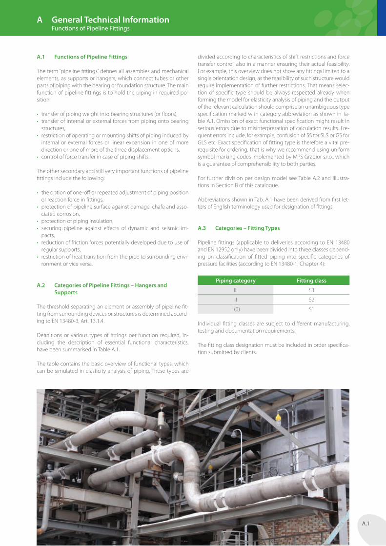
The term “pipeline fi ttings” defi nes all assembles and mechanical elements, as supports or hangers, which connect tubes or other parts of piping with the bearing or foundation structure. The main function of pipeline fi ttings is to hold the piping in required po-sition:
• transfer of piping weight into bearing structures (or fl oors),• transfer of internal or external forces from piping onto bearing
structures,• restriction of operating or mounting shifts of piping induced by
internal or external forces or linear expansion in one of more direction or one of more of the three displacement options,
• control of force transfer in case of piping shifts.
The other secondary and still very important functions of pipeline fi ttings include the following:
• the option of one-off or repeated adjustment of piping position or reaction force in fi ttings,
• protection of pipeline surface against damage, chafe and asso-ciated corrosion,
• protection of piping insulation,• securing pipeline against eff ects of dynamic and seismic im-
pacts,• reduction of friction forces potentially developed due to use of
regular supports,• restriction of heat transition from the pipe to surrounding envi-
ronment or vice versa.
A.2 Categories of Pipeline Fittings – Hangers and Supports
The threshold separating an element or assembly of pipeline fi t-ting from surrounding devices or structures is determined accord-ing to EN 13480-3, Art. 13.1.4.
Defi nitions or various types of fi ttings per function required, in-cluding the description of essential functional characteristics, have been summarised in Table A.1.
The table contains the basic overview of functional types, which can be simulated in elasticity analysis of piping. These types are
divided according to characteristics of shift restrictions and force transfer control, also in a manner ensuring their actual feasibility. For example, this overview does not show any fi ttings limited to a single orientation design, as the feasibility of such structure would require implementation of further restrictions. That means selec-tion of specifi c type should be always respected already when forming the model for elasticity analysis of piping and the output of the relevant calculation should comprise an unambiguous type specifi cation marked with category abbreviation as shown in Ta-ble A.1. Omission of exact functional specifi cation might result in serious errors due to misinterpretation of calculation results. Fre-quent errors include, for example, confusion of SS for SLS or GS for GLS etc. Exact specifi cation of fi tting type is therefore a vital pre-requisite for ordering, that is why we recommend using uniform symbol marking codes implemented by MPS Gradior s.r.o., which is a guarantee of comprehensibility to both parties.
For further division per design model see Table A.2 and illustra-tions in Section B of this catalogue.
Abbreviations shown in Tab. A.1 have been derived from fi rst let-ters of English terminology used for designation of fi ttings.
A.3 Categories – Fitting Types
Pipeline fi ttings (applicable to deliveries according to EN 13480 and EN 12952 only) have been divided into three classes depend-ing on classifi cation of fi tted piping into specifi c categories of pressure facilities (according to EN 13480-1, Chapter 4):
Piping category Fitting class
III S3
II S2
I (0) S1
Individual fi tting classes are subject to diff erent manufacturing, testing and documentation requirements.
The fi tting class designation must be included in order specifi ca-tion submitted by clients.
A General Technical Information Functions of Pipeline Fittings

A.2
Table A.1 – Overview of Fitting Types per Function
Marking abbreviation
Designation Description
RH Rod hanger
Transfer of vertical load by means of suspension on a rigid rod with rigid restriction of vertical shift downwards. Optional height adjustment during installation, for piping exceeding DN80 always during operation too. It must enable deviation of ± 4° from the vertical axis. It can be either single- or double-rod component for vertical or horizontal piping.
SH Spring hanger
Transfer of vertical load by means of suspension using a rod and spring block with linear characteristics. Optional piping shift in vertical direction. Optional adjustment of load during installation or operation. It must enable deviation of ± 4° from the vertical axis. It can be either single- or double-rod component for vertical or horizontal piping.
CH Constant hangerTransfer of vertical load by means of suspension using a rod and spring block with permanent force characteristics, dead load at any spring shift. Other characteristics and versions as the same as for SH.
SS Sliding supportTransfer of vertical load using skid under piping or two skids in vertical pipelines. It enables random shifts in horizontal direction.
VS Variable supportTransfer of vertical load using skid under piping or two skids in vertical pipelines and spring block with linear characteristics. It enables shifts in horizontal direction.
CS Constant supportTransfer of vertical load using skid under piping or two skids in vertical pipelines and spring block with permanent force characteristics, dead load during spring shift. It enables shifts in horizontal direction.
FP Fixed pointStructure that restricts or binds shifts or orientation of piping in any direction. Transfer of three force and three momentum elements.
SLSSliding lift-free support
Sliding support with prevention of shift in positive vertical direction. It enables shifts in horizontal direction.
G2 G4
GuideStructure that enables shift along the pipe axis and restrictions of any other shifts, either backlash-free or with set play (gap). The guide G2 restricts shifts in both ways along one direction; guide G4 restricts shifts in four ways along two directions.
GS Guide supportSliding support that is supplemented with restrictions of shifts in horizontal direction. The shift restricting device is usually fitted on the support base.
GLS Guide lift-free support Guide support that is supplemented with shift restriction in positive horizontal direction.
A Axial stopStructure that enables shift in any direction except for the pipe axis direction, either backlash-free or with set play (gap).
AS Axial stop supportSliding support that is supplemented with shift restrictions along the horizontal axis. The shift restricting device is usually fitted on the support base.
ALSAxial stop lift-free support
Support with a stop that is supplemented with shift restriction in positive vertical direction.
R RetainerStructure that restricts or binds shifts in any direction and still enables any orientation. Transfer of three force elements – fixed momentum point.
RS Rigid strutStructure that enables or binds of shift along one direction, in either both or negative ways, and enables any orientation. There are no friction forces developed in free directions.
SN SnubberA device that enables restriction of shift along one direction, in either both or negative ways, during motion exceeding the threshold velocity. Shifts performed below threshold velocity are slack.
SB Vibration damperAdjustable spring block with shift characteristics for both directions or block with friction mechanism to reduce vibrations or sway.
A General Technical Information Project Engineering – Type Selection

A.3
A.4 Design and Selection of Fitting Type or Assembly
The selection of fi tting type must be performed by an organ-isation executing the piping project, based on results obtained through elasticity analysis of the piping route.
Selection of fi tting type is aided by the following recommenda-tions, even though there is not unambiguous algorithm of choice and some requirements might be contending:
• Selection pursuant to required restrictions of shift (according to Tab. A.1.).
• Selection of type based on location of piping and framework structure – decision between hanger and support.
• Choice between hanger and support based on friction eff ects. In most cases, even interior fi ttings develop corrosion on sliding surfaces over several years, resulting in mutual adhesion corro-sive sticking on exterior applications. Supports should be used with sliding pads with PTFE or base plates made of corrosion-re-sistant steel.
• Choice between hanger and support based on restriction of further shifts (a hanger must be supplemented with another el-ement, supports can be combined into single type applications, e.g. GS).
• Hangers enable (easier) adjustment and do not require any al-terations of sliding surfaces.
• Supports can be used for applications with steel framework structures or fl oor below piping reaches the height of approx. 2 x DN. Supports should be bolstered with posts.
• The clearance of suspended piping must be 2.2 m + downward dilatation.
• The optimal distance between insulation surface and the sup-port base should be 30–50 mm.
• Insulation of hanger caliper is easier and better than support insulation.
• Spring or PTFE sliding surfaces must be always located at the bottom of insulation, with the min. gap of 20 mm.
• Reduction of use of spring or constant support for points with great horizontal shifts.
• Use of supports at manual fi tting points, e.g. by-passes.• Vertical piping should be fi tted primarily with hangers, to ensure
repeated adjustability.• The length of hangers must be suffi cient to ensure that the de-
viation of rod from vertical axis does not exceed ± 4° within the eff ective length between the sleeve connection pin or caliper to the framework mounting pin.
• Primary application of hangers with springs integrated in rods, reduction of assemblies with springs on framework or girder.
• Primary application of single-rod hangers, double-rod ones should be only used in case of lack of space for the minimum length required or collision of rod with piping above the fi tting point.
• Location of spring should be designed in such manner that it is visible from the ground or service platforms, preferably as close to the top fi xing pin (rod sway) as possible.
• Reduction of piping suspension from pipe caliper above.• Pipe bridges should be fi tted with height-adjustable supports.• Reduction of application of hangers on piping with two-phase
medium.• Reduction of application of hangers of 2–3 metres in length on
exterior pipelines.• Reduction of hanger rod length with respect to sway and seis-
micity.
• The fi rst support behind rotary machinery, exchangers or res-ervoirs should be adjustable in height on repeated occasions.
• Small lateral loads should be fi tted preferably with guides of GS or AS type.
• Guides and retainers of piping with requirements for zero fric-tion forces and minimum play should be combined with rigid struts RS.
• Guides and retainers used on pipe bridges should be combined with types GS, GLS, AS or ALS types.
• Short rods and great horizontal shifts of rod hanger should be combined with roller hangers.
• Piping on poles not bound into a bridge should be combined with roller or PTFE supports.
A.5 Selection of Model or Version of Fitting Assembly
The party processing project design for piping realisation must suggest not only the type yet also the model and version of fi t-tings. There is no straight regulation amending their selection, that is why the following Tab. 2 shows an overview of the most important options with description of their characteristics and certain terms and conditions of application. Specifi c models and versions must be defi ned in order specifi cation; the best way is to include a reference to the overview of assemblies according to section B of the catalogue or a sketch, description, remark in the specifi cation chart.
A.6 Load on Structure and Steel Frameworks
Specifi cation of design load on auxiliary structures must include the sum of all elements of permanent load (G), as well as individ-ual elements of the variable and random load (Q) or even direct sums (G + Q). Symbols for designation and defi nition of load clas-sifi cations have been adopted from EN 1990.
Random, variable and extraordinary loads need not be stated, if the following conditions have been met for all fi ttings of a specifi c pipeline:• Fd, Q < 1.15 × Fd, G (design load for Q is less than 1.15 times of
the design load for G).
Calculation errors, deviations and weight of hangers or supports are included into the partial coeffi cient of load reliability, which can be selected (valid for Czech Republic) as follows: γ
F1 = 1.35, γF2 = 1.0, γF3 = 1.0. Design load is determined by structural engi-neering designing the steel or auxiliary framework structure; spec-ifi cations of fi ttings always contain details of load obtained from piping elasticity analysis only.
Specifi cations of steel frameworks must state horizontal elements for support loads or guides or retainers with respect to friction or at least a note to specify the magnitude of friction coeffi cient. The coeffi cient for regular sliding supports is f = 0.3, the value for sup-ports with PTFE is f = 0.08 and the equivalent for roller supports is f = 0.03.
Horizontal elements of design load on hangers should be always considered at the level of 0.1 × Fdz.
Fittings of piping larger than DN80 may not cause strain on girder of auxiliary structure on torsion or local bending of fl ange chords, or it must be verifi ed by means of calculation.
A General Technical Information Project Engineering – Type Selection

A.4
Table A.2 – Summary of assembly versions and fitting components
Designation Description and data for selection Type code designation
Caliper fittings – hangers and supports
Supports, fix points and caliper-pipe guides do not guarantee the option for random axial or displacement slip.
These enable relocation of the fixing point to pipe into the required position during installation (except for hangers for vertical piping, axial retainers and fix points secured to brackets by means of sectional joint, e.g. boss). These are used in locations, where the installation process might be associated with deflection of welded sub-assemblies out of their original locations. These are further recommended for applications with assumed disassembly, e.g. during repairs of connected equipment.
These are convenient mainly for piping with greater operating temperatures, for the reduced risk of crack of piping walls.
These are not suitable for hangers (and supports) for piping larger that DN800, where the caliper weights grow on progressive basis, such applications are therefore recommended for potential application of welded fittings.
The gap between caliper and pipe wall is prone to corrosion, aggressive environment should be therefore fitted with galvanized calipers or brackets.
Hangers – accessory codes X, M, P, K
Supports – product group 6
Struts – product group 4
Welding fittings – hangers
Recommended for bare exterior piping or pipes with large DN dimensions.
These do not enable relocation of the fixing point after element installation (e.g. for shifting of sub-assembly during connection with adjacent spool).
Higher temperatures require consideration of the risk of weld cracks due to thermal expansion.
Welds must be inspected with optional repeated checks during operation (corrosion).
Accessory codes W, V, H
Welding fittings – supports
Recommended for bare exterior and interior piping made of carbon steel.
Reliable connection against slippage on supports, fix points, retainers and guides.
These do not enable relocation of the fixing point after element installation (e.g. for shifting of sub-assembly during connection with adjacent spool).
Welding of supports onto piping result in shrinkage of weld joint and slight reduction of construction height. This is the reason for their application in locations without mounting relief of supports.
Not recommended for higher temperatures due to great length of weld joint resulting in internal stress and subsequent cracks on piping surface.
Product group 5
Guide with single support base
Application for guides or retainers on horizontal piping in combination with support.
Application for pipe bridges and locations that disable construction of framework for guides with multiple bases.
Application for stabilisation guides against wind loads and random effects.
More demanding installation and uneasy play checking.
Supports groupss 5 and 6 with weldments 940, 941, support types 637, 647, 648
Guide with multiple supports
Application for horizontal and vertical piping.
Requires installation of surrounding auxiliary framework.Types 62x, 63x, 64x
A General Technical Information Project Engineering – Type Selection

A.5
Hangers and supports must not be always fi xed on girder fl anges at its web plane, it is therefore recommended to consider appli-cation of ribs at the connection point, depending on the girder class, load, etc.
Prior to commencement of project works, it is necessary to agree on the method for fi ttings of supports on girders – loose or with a sliding plate, either by welding or bolting, with plastic guard plate on the support base for galvanized frameworks.
A.7 Specifi cation of Pipeline Fittings
The specifi cation must always include all the parameters below:
• Marking or identifi cation of item or item group.• Fitting type. It can be specifi ed by abbreviation listed in Table
A.1.• For any special functions required, versions should be specifi ed
according to type or catalogue order number according to the overview of types in section B of the catalogue.
• Type of hanger fi xture or support fi xing onto connected frame-work – e.g. support with sliding plate, hanger with welding joint using a fork etc. (to be specifi ed in remarks fi eld).
• Type of fi xture on piping – welding or caliper (to be specifi ed in remarks fi eld).
• Piping diameters – nominal diameter or outside diameter of piping.
• Piping (tube) material.• Thickness of insulation.• Characteristics dimensions required – hanger length or support
height, spacing of hanger rods, guide bosses, etc.• Design temperature of fi ttings is considered as the highest op-
erating temperature without any add-ons.• Design load (see further).• Design shifts (see further).• Pipe axis orientation at the place of fi tting – diff erentiation be-
tween vertical or horizontal piping at the place of fi tting, as well as specifi cation of pipe axis at the place of fi tting in compliance with the global coordinates system. This specifi cation is impor-tant mainly for supports and guides and determination of re-quired size of support base or dimensions of slip base plates. Sample designation of horizontal pipe at y axis of global coor-dinate system: H-y.
• Spring stiff ness.• Specifi cation of friction coeffi cient required for supports and
guides (to be specifi ed in remarks fi eld).
A.8 Specifi cation of Loads and Shifts
The specifi cation must refer to the following loads separately:
• Set required (for spring fi ttings) or design (for fi xed fi ttings) cold loads, specifi ed following the elasticity analysis. The required load might diff er from cold loads for spring hangers.
• Cold loads – for spring hangers, these are loads for condition with operating or calculation temperature for the most com-mon operating calculation condition (e.g. all piping within system hot). For rod hangers or supports or guides, loads are specifi ed for condition with design temperature, if signifi cantly diff erent from operating temperature (e.g. in chemical industry) or for load conditions with top values.
• Hot shifts – specifi cation of regular operation and variable and separate extraordinary load values for spring and constant hangers. Values for rod hanger and supports or struts are speci-fi ed according to the previous article.
• Random loads Q must be specifi ed (except for fi ttings according to Art. A.6). It is important to state, whether the value refers to summary fi gure for constant load or separate random load only.
• Remark about the sense of eff ect of random loads (one- or two-way) must be added.
• Vertical shifts of spring hangers are specifi ed for nominal op-erating condition. Horizontal shifts of hangers are specifi ed for design condition of piping (design temperature of piping).
• Shifts of supports, guides, retainers etc. are specifi ed for design condition of piping (design temperature of piping).
• The values of play required must be specifi ed for all major di-rections.
• The particular requirements for absence of lift must be specifi ed for lift-free supports or hangers (i.e. struts).
• Supports and guides require absolutely unanimous and unmis-takable specifi cation of maximum shifts within the local system of coordinates, otherwise supports might fall off the framework or sliding plates/rollers may be jammed!
A.9 Auxiliary Steel Frameworks
Auxiliary steel frameworks must be designed in such manner to transfer the load required and ensure suffi cient strength. It is rec-ommended to keep permitted defl ections at the forces-fl ow with pipeline fi ttings reduced to 1–4 mm.
Design load of auxiliary frameworks must be set the same for both structure and steel frameworks.
Anchor plates in concrete ceilings must be provided with at least 2 anchors for piping diameters of DN100 and at least 4 anchors for piping diameters exceeding DN100. Anchoring must be verifi ed by means of calculation, including interactions and thresholds distances, or the system must be built using standard plates (e.g. according to section P of this catalogue).
The auxiliary framework must be designed in such manner to pre-vent twisting of girders. The dimensioning of girders to comply with stability in bend (swerve) must be executed with consider-ation of eff ects produced by lateral forces per each fi tting type.
A.10 Design of Assemblies and Components
With respect to functionality, carrying capacity and permitted loads, individual components and assemblies for pipeline fi ttings made by MPS Gradior s.r.o. are designed according to EN 13480-3:2012, Chapter 13. Fittings manufactured and documented ac-cording to standards VGB R 510-L-Teil 1, ASME B31.1, MSS-SP58, ASME NF-3000, AWS can be supplied on request.
Piping in boiler assemblies, e.g. according to EN 12592 or EN 12953, can be also manufactured using pipeline fi ttings compli-ant with EN 1280-3, as the standards for design and production of boilers contain no instructions for design of non-pressure thrust components, those standards further include no reference to ma-terials used for designing of pipeline fi ttings, as threaded parts, for example. The details stated here must be specifi ed with customer prior to processing of the project design.
A General Technical Information Project Engineering – Type Selection

A.6
The design life of pipeline fittings must match at least the service life of piping and its parts. Unless otherwise stated, the standard design life if set for 200 000 hours or 25 years respectively.
Permitted loads or design load capacity for particular components are defined in the catalogue of pipeline fittings. Values contained in tables have been determined for regular design conditions ac-cording to EN 13480-3, therefore applicable to permanent static load “G” and the design temperature of 80 °C (resp. the minimum ambient temperature of -20 °C) and the initial material group 1. These conditions apply to all catalogue components. Conversion of load capacity to a different temperature, another material of load category has been described in particular sections of the cat-alogue and Article A.25.
Deliveries of guides in S2 and S3 series are accompanied by instal-lation drawing documentation. Type characteristics of supports or calipers and bonds for piping series S1 are documented by means of catalogue sheet only.
Assembly drawings include parts lists, details of installation welds, instructions and data for installation, data referring to loads, shifts, stiffness and design load capacity for fixed fittings.
A.11 Design Temperatures
Design temperatures of pipeline fittings in contact with piping, either bare or insulated, are determined by the supplier of fittings according to relevant regulations or their own methodologies. The specification defined in order for fittings must specify the top operating temperature of piping (not the permitted or design temperature with add-ons, the same rule also applies to boiler piping etc.).
Coefficients for calculation of load capacity for piping fixtures (calipers, supports, etc.) depending on temperature have been
defined for groups of materials used. Design temperature of com-ponents are defined according to EN 13480-3, while the values for multi-link calipers are defined according to methodology imple-mented by manufacturer.
The basic design temperature for any parts of supports, rods and fixtures to framework is 80 °C, or -20 °C respectively. Higher basic design temperature, e.g. 150 °C, can be selected for extraordinary operating conditions as required by project specifications.
Hanger assemblies for piping with DN > 32 or design temperature of 150 °C are always constructed with two hinged joints per rod. Piping with DN => 80 is equipped with an element for straining or additional adjustment of rod during operation.
Extension of rods is permissible by means of threaded parts only, mounting welds of rods or connecting elements are unaccept-able! Hangers are set primarily into vertical position during instal-lation. Rods are pre-deflected in properly reasoned cases only.
The double-rod hanger for horizontal shifts, which cause devia-tion of 2.5° at the rod plane, must be fixed to the framework at a single point only.
Each rod of double-rod hangers used for horizontal piping has been designed to transfer 2/3 of the total hanger load.
Dimensioning of rods used within rod hangers must be per-formed with respect to engineering of piping fixtures. Selection of load per rod within the interval of (0.5–1) × full hanger load can be made, if the design of caliper and retainers enables balancing of caliper inclination.
Double-rod hangers of vertical piping for DN => must be fitted with welded retainers on piping to prevent slippage of bracket and piping connections.
Figure A.1 – Design temperatures of components
0,33xTf
Tf-30°C
Tf
80°C
Tf-30°C
Tf
Tf-20°C
0,5xTf
0,33xTf
Tf-20°C
Tf-20°C
Tf-ex1°C/mm
Tf-30°C
0,33xTf
e
Tf
Tf-20°C
0,33xTf
A General Technical Information Design Requirements

A.7
A.12 Supports
The allowance for shift of sliding supports must be at least 25 mm in each direction and this requirement must be also matched by adaptation of the thrust framework base.
Bracket supports with guides or retainers or guides for high loads must be provided with welded retainers to prevent piping slip-page. The height of bracket supports may not exceed the value stated in catalogue with respect to potential inclination. That applies especially to guided supports. Tipping occurs, when the friction momentum between pipe and bracket is lower than the momentum from friction forces in the support base.
Sliding base surfaces for supports or bolster plates may not be provided with any top coat. Interior applications may be com-pleted with basic coating, the recommended design of exterior applications includes a combination of supports with stainless steel sliding surface and sliding plates with PTFE or sliding varnish coating.
Drawings of guides must state the minimum play required, which is implied by temperature shifts in supporting components and enlargement of pipe diameter.
A.13 Spring and Constant Fittings
Spring or constant fi ttings can be considered with respect to set-ting a higher cold load depending on the weight of moving parts of hanger/support.
Selection of spring size is governed by the rules below:
• A constant hanger or support must enable additional adjust-ment of set load by at least ± 15 %. This adjustment may not reduce the shift required in any way.
• Spring hangers or supports must enable additional adjustment of set load by at least ± 10 % both in hot or cold condition.
Allowances for travel:
• The allowance for travel of a constant spring block in cold or hot threshold position must be 10 % with respect to the calculated (required) shift, however, the minimum value must be 25 mm.
• The allowance of travel of a spring block in cold or hot threshold position must be 10 % with respect to calculated shift, however, the minimum value must be 5 mm.
A.14 Rigid Struts
The minimum design temperature for all parts of assemblies is 150 °C.
The mounting length for any type and size of struts must be re-ad-justable by at least ± 25 mm. The maximum permissible length adjustment (unscrewing of joint heads) is clearly indicated to en-sure the minimum screwing depth.
Joint heads enable the deviation of 6 °.
The total play of rigid strut assembly, including its connecting parts, when using pins or dowel bolts of diameter up to 33 mm,
must be less than 0.5 mm, it must be below 1.5 % of the pin diam-eter for larger diameters.
Permitted reduction of strut chord subject to eccentric pressure is equal to 1 mm per every 1 m of strut length.
For struts subject to cyclic loads, where the load swing exceeds 0.1 × F
p, where Fp refers to the strut load capacity , the piping de-signer must process the project specifi cation stating the number of cycles required and swing amplitude.
For fi tting nodes with large axial deviations during dynamic ef-fect, the design engineer must consider application of welded retainers to secure the piping caliper in plane perpendicular to the pipe axis; and further against rotation, which might result in loss of stability of the triple joint mechanism combining a caliper, a strut and a fork.
A.15 Mounting Welded Joints
Mounting welds are most often found on fi xing of hanger rods to framework. The welded joints must be fi nished as closed for any type of connections. Single-layer welds are acceptable for welding of rod loops or forks sized M10 and M12 only. Welding method 111 is recommended for fl at welding loops. Method 135 is applicable in properly reasoned cases only.
Welds of pins or weldments on piping are processed according to documentation supplied by piping manufacturer. The piping manufacturer must provide the supplier of fi ttings with technical specifi cation detailing the pipe material to ensure mutual weld-ability of both parts to be connected as well as their identical or similar thermal expansion. Welds on fl at retainers must be always closed. Circular retainers or pinions can be fi xed by means of fully bitten into unilateral corner welds.
The welding plan for mounting connections must be processed by the supplier of piping together with details of method and non-destructive testing required.
Girder fl anges fi xed with welding loops or hanger forks subject to great loads (approximately exceeding 50 kN) must be checked for potential duplications at the connection point.
Welded joints must be fi nished to comply with quality class C, as defi ned by ISO 5817.
When welding surfaces treated with a workshop coating, which the manufacturer has not designated for welding, the coating must be abraded to the distance of at least 20 mm from the edge of weld prior to welding process.
Any welding of threaded parts is unacceptable, except for rods of hangers made of carbon steel with guaranteed weldability char-acteristics. Welds must be always subject to volume check with respect to potential penetration and interior defects!
Welds of cradles or fl at retainers on piping and welding loops or forks must be fi nished as closed.
The surface fi nishing of mounting joints must be always complet-ed in accordance with project specifi cation (corrective and top coat).
A General Technical Information Design Requirements

A.8
A.16 Selection of Assemblies of Hangers, Supports and Piping Guides from Pipeline Fittings Catalogue
Basic type assemblies of hangers and supports for piping are in-cluded in section B of the catalogue. The said standard assemblies are functioning reliably and proven, comprising type catalogue components. These assemblies comply with requirements de-fined by standards EN 13 480-3, VGB R 510-L-Teil 1, ASME B31.3 and MSS-SP58.
Selection of pipeline fitting assembly follows the specific require-ment, based on type and function, in accordance with Tab. A.1. Parameters of load or design temperature are respected by the supplier of fittings, selection of material finishing or the compo-nent load capacity class.
All the data required for specification of pipeline fittings can be found in the standard data sheet. It can be downloaded from www.mps-gradior.cz in MX Excel format. We recommend the use of our data sheets, as these are structured to aid processing of unambiguous orders ad users are also supported by explanato-ry notes. The unified form of orders is always best understood by both the client and manufacturer.
A.17 Coding of Assemblies with Type Numbers
Type assemblies of pipeline fittings can be identified using a sim-ple designation code that contains all the basic dimension data,
details of nominal load and material of the part in contact with piping. The code can be used for checking or simple specification, for example, it is stated in the quotation sheet or delivery note for particular order.
For structure of this code see the review of assemblies on the fol-lowing pages B.7 to B.12.
A.18 Description and Selection of Components
Correct master specification of hanger or supports requires and actually suffices with selection of type and finishing, as described in par. A.2–A.10. Selection of parts to form the assembly is per-formed by supplier of fittings; and that is based on assessment of load capacity, shifts, operating reliability, weight and price.
The catalogue of pipe fittings of MPS Gradior s.r.o. contains further data sheets with main technical and mounting-operation data for the relevant components. These components are designed as ver-satile and reliable parts contained within type assemblies shown in section B of the catalogue.
Components for particular assemblies have been clearly divided into so called “product groups” determined with respect to the nature of products (spring cages, weldments, threaded parts, etc.) and further according to functional classification within assem-blies. For a summary of product groups see Tab. A.3.
A General Technical Information Summary of Production Groups

A.9
Table A.3 – Summary of Product Groups
Product Group Description Type/Form
1 Spring cages
Nominal travel 50 mmNominal travel 100 mmNominal travel 200 mmNominal travel 300 mm
2 Constant force cagesNominal travel 150 mmNominal travel 300 mmNominal travel 450 mm
3 Girders, brackets
L-girder light Standard girderSpring connection girderDirect support girder
4 Dynamic elements
Joint strutsJoint struts with playHorizontal calipersVertical calipersConnecting fork
5 Welding bosses and supports
Sliding supports, guides and anchor basesBosses for vertical pipingBosses and cradles for piping of large diametersTube supports
6 Clamp supports
Sliding supportsFixed or adjustable heightsMounting adjustable itemsGuidesBosses for vertical pipingAnchor bases and fi xed points
6N Supports for non-metal piping
Sliding supportsGuidesBosses for vertical pipingAnchor bases and fi xed points
7 Calipers, clampsFor horizontal pipingFor vertical pipingSpecial
7N Clamps for non-metal pipingFor horizontal pipingFor vertical piping
8 Joining components
Thread barsTensionersLoops and forksPins
9 Connecting componentsWelding loops and forksSpherical padsConnection to sections
P Sliding plates
Support base platesSliding plates with PTFESliding plates with bronze-graphite or stainless-graphiteInsulation and space-fi llingGuide plates
S Special parts
Supports and hangers for pre-insulated pipingSupports and hangers for cryogenic pipingDirect rollersRoller guidesMultidirectional rollers
A General Technical Information Summary of Product Groups
A.10
A.19 Design Load Capacity and Permitted Loads
Catalogue sheets contain data about nominal and permitted load corresponding with design load capacity of each item and dimension. Springs are coupled with nominal load data that is equal to the force of spring for maximum operating compression. Other fixed parts are assigned with permitted load that is usually expressed by means of single value for vertical, ensile or pressure force elements. Even though some materials might refer to this single element only, component design is always considered with respect to other force elements as well, e.g. friction force at supports or horizontal force element for deviation of hanger rods. Guides or fixed points are defined with several elements of per-mitted load or even mutual relations between them.
Design load capacities of components are calculated according to requirements in EN 13480-3: 2012, EN 1993, VGB R 510-L-Teil 1, ASME B31.1, B31.3 and MSS-SP58. In case of any deviation among these standards, the so called “stricter requirement” will take prej-udice.
Deliveries of fittings for nuclear facilities according to ASME NF-3000 require corrections of catalogue load capacity data. Coeffi-cients for individual components need to be obtained from the manufacturer by inquiry.
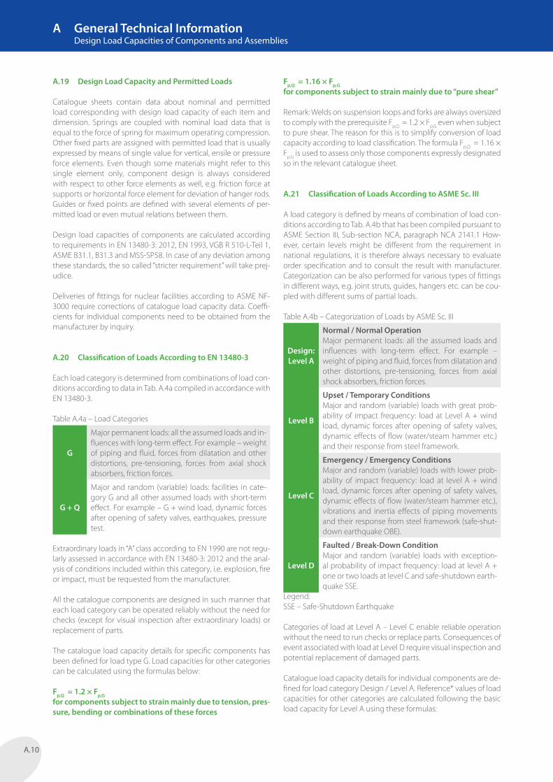
A.20 Classification of Loads According to EN 13480-3
Each load category is determined from combinations of load con-ditions according to data in Tab. A.4a compiled in accordance with EN 13480-3.
Table A.4a – Load Categories
G
Major permanent loads: all the assumed loads and in-fluences with long-term effect. For example – weight of piping and fluid, forces from dilatation and other distortions, pre-tensioning, forces from axial shock absorbers, friction forces.
G + Q
Major and random (variable) loads: facilities in cate-gory G and all other assumed loads with short-term effect. For example – G + wind load, dynamic forces after opening of safety valves, earthquakes, pressure test.
Extraordinary loads in “A” class according to EN 1990 are not regu-larly assessed in accordance with EN 13480-3: 2012 and the anal-ysis of conditions included within this category, i.e. explosion, fire or impact, must be requested from the manufacturer.
All the catalogue components are designed in such manner that each load category can be operated reliably without the need for checks (except for visual inspection after extraordinary loads) or replacement of parts.
The catalogue load capacity details for specific components has been defined for load type G. Load capacities for other categories can be calculated using the formulas below:
Fp,Q = 1.2 × Fp,Gfor components subject to strain mainly due to tension, pres-sure, bending or combinations of these forces
Fp,Q = 1.16 × Fp,Gfor components subject to strain mainly due to “pure shear”
Remark: Welds on suspension loops and forks are always oversized to comply with the prerequisite Fp,Q = 1.2 × Fp,G even when subject to pure shear. The reason for this is to simplify conversion of load capacity according to load classification. The formula Fp,Q = 1.16 × Fp,G is used to assess only those components expressly designated so in the relevant catalogue sheet.
A.21 Classification of Loads According to ASME Sc. III
A load category is defined by means of combination of load con-ditions according to Tab. A.4b that has been compiled pursuant to ASME Section III, Sub-section NCA, paragraph NCA 2141.1 How-ever, certain levels might be different from the requirement in national regulations, it is therefore always necessary to evaluate order specification and to consult the result with manufacturer. Categorization can be also performed for various types of fittings in different ways, e.g. joint struts, guides, hangers etc. can be cou-pled with different sums of partial loads.
Table A.4b – Categorization of Loads by ASME Sc. III
Design: Level A
Normal / Normal OperationMajor permanent loads: all the assumed loads and influences with long-term effect. For example – weight of piping and fluid, forces from dilatation and other distortions, pre-tensioning, forces from axial shock absorbers, friction forces.
Level B
Upset / Temporary ConditionsMajor and random (variable) loads with great prob-ability of impact frequency: load at Level A + wind load, dynamic forces after opening of safety valves, dynamic effects of flow (water/steam hammer etc.) and their response from steel framework.
Level C
Emergency / Emergency ConditionsMajor and random (variable) loads with lower prob-ability of impact frequency: load at level A + wind load, dynamic forces after opening of safety valves, dynamic effects of flow (water/steam hammer etc.), vibrations and inertia effects of piping movements and their response from steel framework (safe-shut-down earthquake OBE).
Level D
Faulted / Break-Down ConditionMajor and random (variable) loads with exception-al probability of impact frequency: load at level A + one or two loads at level C and safe-shutdown earth-quake SSE.
Legend:SSE – Safe-Shutdown Earthquake
Categories of load at Level A – Level C enable reliable operation without the need to run checks or replace parts. Consequences of event associated with load at Level D require visual inspection and potential replacement of damaged parts.
Catalogue load capacity details for individual components are de-fined for load category Design / Level A. Reference* values of load capacities for other categories are calculated following the basic load capacity for Level A using these formulas:
A General Technical Information Design Load Capacities of Components and Assemblies
A.11
A.23 Supports
Each support is assigned with specifi c permitted load value de-pending on its type and dimension; supports are therefore not grouped into load classes. The permitted load of supports is gov-erned by rules described in catalogue sheets.
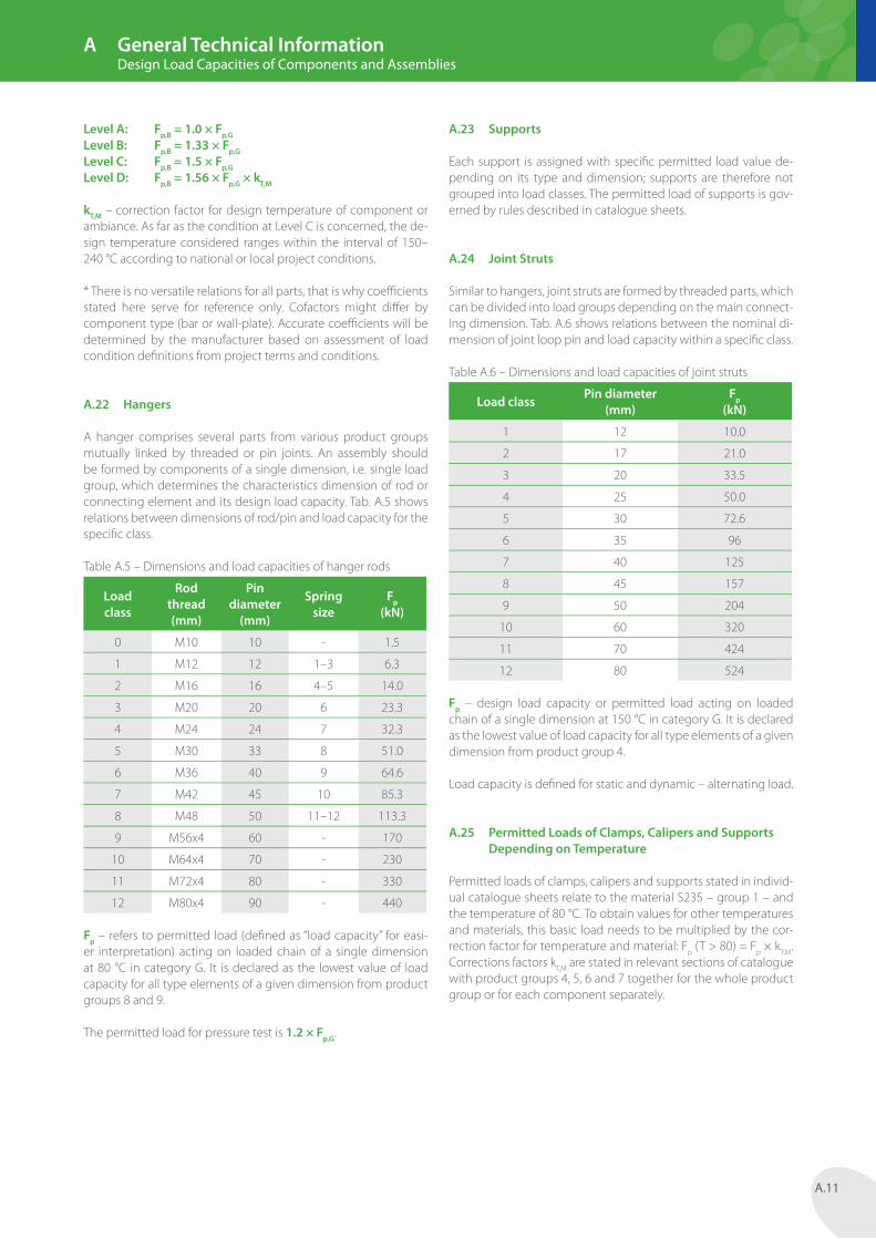
A.24 Joint Struts
Similar to hangers, joint struts are formed by threaded parts, which can be divided into load groups depending on the main connect-ing dimension. Tab. A.6 shows relations between the nominal di-mension of joint loop pin and load capacity within a specifi c class.
Table A.6 – Dimensions and load capacities of joint struts
Load classPin diameter
(mm)Fp
(kN)
1 12 10.0
2 17 21.0
3 20 33.5
4 25 50.0
5 30 72.6
6 35 96
7 40 125
8 45 157
9 50 204
10 60 320
11 70 424
12 80 524
Fp – design load capacity or permitted load acting on loaded chain of a single dimension at 150 °C in category G. It is declared as the lowest value of load capacity for all type elements of a given dimension from product group 4.
Load capacity is defi ned for static and dynamic – alternating load.
A.25 Permitted Loads of Clamps, Calipers and Supports Depending on Temperature
Permitted loads of clamps, calipers and supports stated in individ-ual catalogue sheets relate to the material S235 – group 1 – and the temperature of 80 °C. To obtain values for other temperatures and materials, this basic load needs to be multiplied by the cor-rection factor for temperature and material: Fp (T > 80) = Fp × kT,M. Corrections factors kT,M are stated in relevant sections of catalogue with product groups 4, 5, 6 and 7 together for the whole product group or for each component separately.
A General Technical Information Design Load Capacities of Components and Assemblies
Level A: Fp,B = 1.0 × Fp,GLevel B: Fp,B = 1.33 × Fp,GLevel C: Fp,B = 1.5 × Fp,GLevel D: Fp,B = 1.56 × Fp,G × kT,M
kT,M – correction factor for design temperature of component or ambiance. As far as the condition at Level C is concerned, the de-sign temperature considered ranges within the interval of 150–240 °C according to national or local project conditions.
* There is no versatile relations for all parts, that is why coeffi cients stated here serve for reference only. Cofactors might diff er by component type (bar or wall-plate). Accurate coeffi cients will be determined by the manufacturer based on assessment of load condition defi nitions from project terms and conditions.
A.22 Hangers
A hanger comprises several parts from various product groups mutually linked by threaded or pin joints. An assembly should be formed by components of a single dimension, i.e. single load group, which determines the characteristics dimension of rod or connecting element and its design load capacity. Tab. A.5 shows relations between dimensions of rod/pin and load capacity for the specifi c class.
Table A.5 – Dimensions and load capacities of hanger rods
Load class
Rod thread (mm)
Pin diameter
(mm)
Spring size
Fp (kN)
0 M10 10 - 1.5
1 M12 12 1–3 6.3
2 M16 16 4–5 14.0
3 M20 20 6 23.3
4 M24 24 7 32.3
5 M30 33 8 51.0
6 M36 40 9 64.6
7 M42 45 10 85.3
8 M48 50 11–12 113.3
9 M56x4 60 - 170
10 M64x4 70 - 230
11 M72x4 80 - 330
12 M80x4 90 - 440
Fp – refers to permitted load (defi ned as “load capacity” for easi-er interpretation) acting on loaded chain of a single dimension at 80 °C in category G. It is declared as the lowest value of load capacity for all type elements of a given dimension from product groups 8 and 9.
The permitted load for pressure test is 1.2 × Fp,G.

A.12
A.26 Materials
Materials used for manufacturing of components for pipeline fit-tings are in accordance with requirements for industrial piping EN 13480-2 and regulations for steel structures EN 1090-2 as well as requirements defined by regulations VGB R 510-L-Teil 1. Fittings compliant with ASME specifications, where materials meet re-quirements set by ASME B31.1 and MSS-SP58 can be supplied on request.
Table A.7 – Ferritic and Low Alloy Steel
Mat
eria
l gr
oup
Pipe
line
fittin
g co
mpo
nent
s
Mat
eria
l EN
Mat
eria
l A
STM
App
licat
ion
tem
pera
ture
1
Clamps S235JR A36
-20/ +350 °C
Circular calipers
S235JR A36
Sheets S235JR A36
Sections S235JR A36
Seamless pipes
P235GH A53
Longitudinal welded pipes
P235GH A513 TP1
Bolts 8.8 -
Nuts 8 -
Thread bars up to M16 M20–M48
8.8 S355J0 -
2
Clamps P265GH A516 Gr70
-30/ +450 °C
Sheets P265GH A516 Gr70
Seamless pipes
P265GH A105
Bolts 42CrMo4 A194 GrB7
Nuts 42CrMo4 A193 Gr2H
3
Clamps 16Mo3 A217 WC1
-20/ +520 °C
Sheets 16Mo3 A204 GrB
Seamless pipes
16Mo3 A335 P1
Bolts 24CrMoV55 A193 B16
Nuts 24CrMo5 A194 Gr4
Table A.8 – Alloy steel
Mat
eria
l gr
oup
Pipe
line
fittin
g co
mpo
nent
s
Mat
eria
l EN
Mat
eria
l A
STM
App
licat
ion
tem
pera
ture
4
Clamps 10CrMo910 A387-22
+450/ +580 °C
Sheets 10CrMo910 A387-22
Seamless pipes
10CrMo910 A335-P22
Bolts 21CrMoV57 A193 B16
Nuts 21CrMoV57 A194 Gr4
To ensure better legibility, materials have been divided into ma-terial groups, where each groups contains materials with similar characteristics – strength characteristics depending on temper-ature. Groups are limited by permitted operating temperature intervals only.
For summary of material group with division of material designa-tions for various components see Tab. A.7 to A.10.
Table A.9 – Fine grain steel for low temperature applications
Mat
eria
l gr
oup
Pipe
line
fittin
g co
mpo
nent
s
Mat
eria
l EN
Mat
eria
l A
STM
App
licat
ion
tem
pera
ture
5
Clamps P275NL A516 Gr60
-50/ +350 °C
Circular calipers
P275NH -
Sheets P275NL A516 Gr60
Sections S235J2 -
Seamless pipes
P275NL A333 Gr6
Longitudinal welded pipes
P275NL A516 Gr60
Bolts 42CrMo4 A320L7
Nuts 42CrMo4 A194Gr4S4
Thread bars 42CrMo4 A320L7
Table A.10 – Austenitic steel
Mat
eria
l gr
oup
Pipe
line
fittin
g co
mpo
nent
s
Mat
eria
l EN
Mat
eria
l A
STM
App
licat
ion
tem
pera
ture
6
Clamps 1.4301 TP 304
-200/ +400 °C
Circular calipers
1.4301 TP 304
Sheets 1.4301 TP 304
Sections 1.4301 TP 304
Seamless pipes
1.4301 TP 304
Bolts A4-70 A194-B8M
Nuts A2-50 A194-8S1
7
Clamps 1.4541 TP 316
+400/ +500 °C
Circular calipers
1.4541 TP 316
Sheets 1.4541 TP 316
Bolts 1.4948 A193-B8T
Nuts 1.4948 A194-8S1
8
Clamps 1.4948 TP 304H
+540/ +650 °C
Sheets 1.4948 TP 304H
Seamless pipes
1.4948 TP 304H
Bolts 1.4948 TP 304H
Nuts 1.4948 TP 304H
A General Technical Information Summary of Materials