a glucose/o2 biofuel cell based on graphene and
TRANSCRIPT

Int. J. Electrochem. Sci., 7 (2012) 8064 - 8075
International Journal of
ELECTROCHEMICAL SCIENCE
www.electrochemsci.org
A Glucose/O2 Biofuel Cell Based on Graphene and Multiwalled
Carbon Nanotube Composite Modified Electrode
Balamurugan Devadas, Veerappan Mani, Shen-Ming Chen*
Department of Chemical Engineering and Biotechnology, National Taipei University of Technology,
No.1, Section 3, Chung-Hsiao East Road , Taipei 106, Taiwan (R.O.C). *E-mail: [email protected]
Received: 17 July 2012 / Accepted: 8 August 2012 / Published: 1 September 2012
We have constructed a glucose/O2 biofuel cell (BFC) with electrochemically reduced graphene oxide -
multiwalled carbon nanotube (ERGO-MWCNT) modified glassy carbon electrode (GCE) as anode and
graphene-Pt composite modified GCE as cathode. The electrochemical characterization results show
that enzyme GOx was well immobilized onto the composite modified electrode. Moreover the
composite modified film exhibits excellent catalytic ability towards the oxidation of glucose in the
presence of redox mediator hydroquinone (HQ). Graphene –Pt composite has been prepared by simple
sodium borohydride reduction method and characterized. The graphene-Pt composite modified GCE
shows good electrocatalytic activity towards O2 reduction. A membraneless glucose/O2 biofuel cell
(BFC) has been developed by employing ERGO-MWCNT modified GCE as anode and graphene- Pt
as cathode. The maximum power density of 46 W cm-2
was achieved for the constructed biofuel. The
results showed that graphene based composites are potential candidates for the development of
efficient biofuel cells.
Keywords: ERGO-MWCNT, hydroquinone, cathode, O2 reduction, biofuel cell.
1. INTRODUCTION
Biofuel cells (BFCs) are special kind of fuel cells, employing enzymes as the biocatalyst for the
conversion of chemical energy into electrical energy [1]. Although, BFCs have been known for long
time [2], they catch enormous attention only in the recent years and are expected to be one of the
promising next generation green energy devices. BFCs have numerous applications in the fields such
as implantable devices [3], waste water treatment [4], drug delivery [5] and biosensors [6]. The
important advantageous of BFCs over other conventional fuel cells are selectivity of the enzyme
Int. J. Electrochem. Sci., Vol. 7, 2012
8065
towards fuel and highly feasible working conditions such as physiological pH and ambient temperature
[7]. Besides, the fuels for BFCs are from renewable energy sources usually sugars or organic acids and
most often glucose [8]. However, BFCs also have certain drawbacks such as poor stability because of
the short lifetime of enzyme and low power densities [7]. Electrons can be transferred between the
electrode and the active site either with the aid of mediators (Mediated electron transfer) or without
any mediators (Direct electron transfer) [9]. Since the redox centre of the enzyme is deeply buried into
the protein chains, generally mediators are adopted to shuttle the electrons between the enzymes and
electrodes which eventually enhances the efficiency and power density of the BFCs [10, 11]. Among
different kinds of BFCs, glucose/O2 biofuel cell is the most studied, where glucose oxidation occurs at
the anode and oxygen reduction occurs at the cathode [12, 13].
Owing to its unique structural and electronic properties, carbon nanotubes (CNTs) find
outstanding applications in various research areas [14-16]. Until now, numerous enzymatic BFCs were
developed based on CNTs modified electrode. L. Mao et al. developed a glucose/O2 BFC based on
single walled carbon nanotube (SWNT) with glucose dehydrogenase (GDH) as the anode biocatalyst
with NAD+ as the cofactor and laccase as the cathode biocatalyst [17]. S.Dong et al. demonstrated a
BFC using multiwalled carbon nanotubes (MWCNT) - ionic liquid gel modified graphite electrodes as
the matrix [18]. Z. Iqbal et al. reported a Membrane-less and mediator-free direct electron transfer
enzymatic BFCs with bioelectrodes comprised of single wall carbon nanotubes (SWNTs) deposited on
porous silicon (pSi) substrates [19].
Recently, graphene 2D carbon material composed of a monolayer of sp2 bonded carbon atoms
has attracted great attention and emerged as a promising material, due to its interesting
physicochemical properties [20-23]. In the recent years, several strategies have been employed for the
exploitation of graphene material based modified electrodes towards biofuel cell applications. W.
Zheng et al. constructed a nanographene platelets (NGPs)-based glucose/O2 biofuel cell (BFC) with
glucose oxidase (GOx) as the anode and the laccase as the cathode [24]. C. Liu et al. developed a
miniaturized membraneless glucose/O2 biofuel cell based on the surface engineering of graphene-GOx
composite [25]. C.Z. Li et al. employed silica sol–gel immobilized graphene sheets composite as a
matrix for the immobilization of enzymes in both anode and cathode platform and successfully
developed a membraneless BFC [26].
Herein, we use a simple and efficient approach to harvest the excellent electrochemical
properties of both MWCNT and graphene by combining them via non-covalent π-π stacking
interactions. We utilize graphene oxide (GO), an oxygenated derivative of graphene as a precursor to
prepare graphene oxide - MWCNT composite by simple sonication approach [27, 28]. Afterwards, the
composite was electrochemically reduced and employed for GOx immobilization [29]. Further, we
prepared graphene - Pt composite by simple sodium borohydride reduction and employed as a cathode
material [30]. At last, we successfully constructed a BFC with ERGO-MWCNT/GOx/Nf modified
GCE as anode for the oxidation of glucose and Graphene/Pt modified GCE as cathode for the O2
reduction [scheme 1].

Int. J. Electrochem. Sci., Vol. 7, 2012
8066
2. EXPERIMENTAL
2.1 Reagents
MWCNT (bundled > 95%, O.D × I.D × length of 7-15 nm × 3-6 nm × 0.5-200 μm), graphite
(powder, <20 μm) and GOx (type x-s from aspergillus Niger) were purchased from sigma-Aldrich and
used as received. 5 wt% nafion (Nf) was purchased from Aldrich and the required Nf concentrations
were prepared using 95% pure ethanol. The mediator hydroquinone (HQ) was purchased from Alfa
Aesar. All the reagents used were of analytical grade and used without purification. The supporting
electrolyte used for electrochemical studies was 0.1 M Phosphate buffer solution (PBS), prepared
using Na2HPO4 and NaH2PO4 and the pH was adjusted either using H2SO4 or NaOH.
2.2 Apparatus
The electrochemical measurements were carried out using CHI 611a work station with a
conventional three electrode cell using BAS GCE as working electrode (area 0.07 cm2), Ag|AgCl (sat.
KCl) as reference electrode and Pt wire as counter electrode. Amperometric measurements were
performed with analytical rotator AFMSRX (PINE instruments, USA) with a rotating disc electrode
(RDE) having working area of 0.24 cm2. Glucose solution was kept aside for one day to achieve
mutarotation. Prior to each experiment, all the solutions were deoxygenated by purging pre-purified N2
gas for 15 min unless otherwise specified. Surface morphological studies were carried out using
Hitachi S-3000 H scanning electron microscope (SEM). Energy dispersive X-ray (EDX) spectra was
recorded using HORIBA EMAX X-ACT (Sensor + 24V=16 W, resolution at 5.9 keV).
2.3 Fabrication of Anode
Graphite oxide was prepared by modified Hummer’s method [31] and it was dispersed in
water. The as-prepared graphite oxide was exfoliated through ultrasonication for 2 h. Then, it was
centrifuged for 30 min at 4000 rpm and the yellowish brown supernatant containing GO platelets were
separated and used for the composite preparation. Then 5 mg of MWCNT was added into 10 ml of
aqueous GO solution (0.5 mg mL-1
) and the resulting mixture was subjected to ultrasonication for 2 h.
Two consecutive centrifugation cycles (30 min each) at 8000 and 14000 RPM have been performed to
remove the excess amount of MWCNT and GO [27]. Thus obtained GO-MWCNT was washed with
water, overnight dried and redispersed in water at the concentration of 0.5 mg mL-1
. For comparative
study, pristine GO and MWCNT dispersions were also prepared in water and DMF solvents
respectively.
GCE surface was polished well with 0.05 µm alumina slurry using a Buehler polishing kit, then
washed with water, ultrasonicated and dried. 5 µl of GO-MWCNT dispersion was drop casted onto the
pre-cleaned GCE and dried at room temperature for 20 min. The composite film modified GCE was
gently washed with water and transferred to an electrochemical cell containing 0.1 M PBS (pH 5). It
was electrochemically reduced by performing 3 successive cyclic voltammograms in the potential
Int. J. Electrochem. Sci., Vol. 7, 2012
8067
range of 0 to -1.5 V [29]. As evident from the Fig.1A, a large cathodic peak was appeared at -1.1 V
corresponding to the electrochemical reduction of oxygen functionalities of GO. The onset potential (-
0.3) was comparatively lower than that of pristine GO (-0.75 V), indicating considerable promotion of
GO reduction after incorporating with MWCNT [20]. The electrochemically reduced GO-MWCNT
(ERGO-MWCNT) composite film modified GCE was washed with water and dried. After that 6 µl (10
mg mL-1
) of GOx was evenly distributed on the composite modified GCE and dried at ambient
conditions. Finally 2µl (0.5%) of Nf was drop casted onto the surface of modified electrode to avoid
the GOx leaching. Thus obtained ERGO-MWCNT/GOx/Nf composite film modified GCE was rinsed
with water and stored in PBS when not in use.
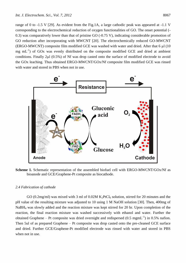
Scheme 1. Schematic representation of the assembled biofuel cell with ERGO-MWCNT/GOx/Nf as
bioanode and GCE/Graphene-Pt composite as biocathode.
2.4 Fabrication of cathode
GO (0.2mg/ml) was mixed with 3 ml of 0.02M K2PtCl6 solution, stirred for 20 minutes and the
pH value of the resulting mixture was adjusted to 10 using 1 M NaOH solution [30]. Then, 400mg of
NaBH4 was slowly added and the reaction mixture was kept stirred for 20 hr. Upon completion of the
reaction, the final reaction mixture was washed successively with ethanol and water. Further the
obtained Graphene – Pt composite was dried overnight and redispersed (0.5 mgmL-1
) in 0.5% nafion.
Then 5ul of as prepared Graphene – Pt composite was drop casted onto the pre-cleaned GCE surface
and dried. Further GCE/Graphene-Pt modified electrode was rinsed with water and stored in PBS
when not in use.

Int. J. Electrochem. Sci., Vol. 7, 2012
8068
3. RESULTS AND DISCUSSION
3.1. SEM and EDX Characterization of anode
Fig. 1 shows the SEM images of ERGO-MWCNT (B), ERGO-MWCNT/GOx (C) and ERGO-
MWCNT/GOx/Nf (D) modified electrodes.
Figure 1. (A) Electrochemical reduction of GO-MWCNT composite for 3 cycles in N2 saturated PBS
(pH 5) at the Scan rate of 50 mVs-1
. SEM images of ERGO-MWCNT (B), ERGO-
MWCNT/GOx (C) and ERGO-MWCNT/GOx/Nf (D).
Figure 2. EDX spectra of GO (A), MWCNT (B), GO-MWCNT (C) and ERGO-MWCNT (D).

Int. J. Electrochem. Sci., Vol. 7, 2012
8069
SEM image of ERGO-MWCNT composite clearly indicating that tubular network of MWCNT
were firmly attached with graphene sheets. After GOx incorporated into the film, the morphology
becomes totally different from that of only composite. The SEM image ERGO-MWCNT/GOx seems
to be GOx molecules were uniformly distributed on the surface of the ERGO-MWCNT modified film.
This clogged morphology of GOx showed that more amount of GOx molecules were
immobilized onto the ERGO-MWCNT surface. High GOx coverage has been achieved owing to the
good affinity of the composite towards GOx. Further, the SEM image of ERGO-MWCNT/GOx/Nf
modified film shows the characteristic nafion morphology along with small cavities, resulting because
of solvent vaporization during the drying process of electrode fabrication [32].
Fig. 2 shows the EDX spectra of GO (A), MWCNT (B), GO-MWCNT (C) and ERGO-
MWCNT (D) modified films. All the modified films contain almost same proportion of carbon content
while variation in the oxygen proportion which find a way to monitor the formation of composite.
EDX profile of GO exhibited oxygen weight % of 45.66, attributed to the presence of oxygen
functionalities (hydroxyl, epoxy and carboxyl groups) on the surface of grpahene sheets and also
indicating versatile oxidation has been achieved. On the other hand, EDX profile of MWCNT exhibits
carbon wt. % of 88.85 and oxygen wt. % of 11.15. Here, the presence of oxygen content might be
caused by the moisture adsorbed on the film of MWCNT modified film. Interestingly, EDX profile of
GO-MWCNT exhibits carbon wt. % of 70.65 and oxygen wt. % of 29.35. A significant increase in the
oxygen wt. % has been achieved comparing with pristine MWCNT and GO-MWCNT. The increased
oxygen content of GO-MWCNT is due to the association of GO with MWCNT, which gives evidence
for the composite formation. EDX profile of GO-MWCNT exhibits carbon wt. % of 84.87 and oxygen
wt. % of 15.13. When, comparing the EDX profile of GO-MWCNT (C) and ERGO-MWCNT(D), a
considerable decrease in oxygen wt. % was observed from 29.35 to 15.13, revealing the substantial
reduction of oxygen functionalities through the electrochemical reduction. Thus, EDX spectra
confirming the formation of ERGO-MWCNT formation by comparing the carbon and oxygne wt. %.
3.2. Electrochemical characterization of the anode
Fig. 3A shows the cyclic voltammograms (CVs) obtained at ERGO (a), MWCNT (b), ERGO-
MWCNT (c) ERGO-MWCNT/GOx/Nf film modified GCEs in N2 saturated 0.1M PBS at the scan rate
of 50mVs-1
. In the absence of GOx, no redox peaks were obtained for ERGO, MWCNT [33], ERGO-
MWCNT modified films, whereas well defined sharp redox peak has been obtained when GOx was
immobilized onto the ERGO-MWCNT modified GCE. The redox couple have a formal potential (Eº')
of -0.430 with a low peak to peak separation value (ΔEp) of 29 mV. Evidently the redox peak obtained
for ERGO-MWCNT/GOx/Nf is ascribed to the direct electrochemistry of GOx (FAD/FADH2) at the
ERGO-MWCNT modified film. Besides, the low ΔEp value achieved on the composite modified
electrode shows that GOx is highly immobilized onto the modified film which accelerates the electron
transfer between the active sites of enzyme and electrode surface. The probable reason for the efficient
electron shuttling behavior of ERGO-MWCNT is the synergistic effect of ERGO and MWCNT. Since,
both ERGO and MWCNT have large surface area and high conductivity, the combination of both as

Int. J. Electrochem. Sci., Vol. 7, 2012
8070
composite could harvest all the excellent properties of the two carbon materials. Hence the composite
exhibits combined large surface area which assists more enzyme loading and leads to the direct
electrochemisty of GOx. Moreover, the high conductivity of the composite directs the enhanced peak
currents than the pristine MWCNT or ERGO.
Fig. 3B shows the cyclic voltammograms obtained at ERGO-MWCNT/GOx/Nf composite film
modified GCE in deoxygenated PBS of pH 7 at different scan rates. The redox peak currents linearly
increased with the scan rates from 10 to 100 mVs−1
(Inset to Fig. 3B), indicating a surface-controlled
process.
Figure 3. (A) CVs obtained at ERGO (a), MWCNT (b), ERGO-MWCNT (c) ERGO-
MWCNT/GOx/Nf film modified GCEs in N2 saturated 0.1M PBS at the scan rate of 50mVs-1
.
(B) CVs of ERGO-MWCNT/GOx/Nf film modified GCE at various scan rates (from inner to
outer: 10, 20, 30, 40, 50, 60, 70, 80, 90 and 100 mVs-1
). Inset is the plot of scan rate versus Ipa
and Ipc.

Int. J. Electrochem. Sci., Vol. 7, 2012
8071
3.3 Electrocatalysis towards glucose in the presence of HQ
Figure 4. CVs of ERGO-MWCNT/GOx/Nf modified GCE in N2 saturated PBS (pH 7) containing 0.5
mM Hydroquinone in the absence of glucose (a) and presence of 10 mM glucose (b) at the scan
rate of 50 mVs-1
.
Fig. 4 shows the CVs of ERGO-MWCNT/GOx/Nf modified GCE in N2 saturated 0.1M PBS
(pH 7) containing 0.5 mM Hydroquinone in the absence of glucose (a) and presence of 10 mM glucose
with the scan rate of 50 mVs-1
. Cyclic voltammograms of ERGO-MWCNT/GOx/Nf modified GCE
exhibited characteristic well defined redox peaks of hydroquinone in the absence of glucose. This
redox peaks are the characteristic redox reaction of HQ centered at approximately 0.08 V [12, 34]. The
anodic current begins to increase from more negative potential, which has significant advantages for
the biofuel cell applications [35, 36]. Since, more negative potential will increase the cell voltage,
which obviously increase the output current of the biofuel cell. Thus, the ERGO-MWCNT/GOx/Nf
modified GCE exhibited efficient and enhanced electrocatalytic ability towards mediated electro-
oxidation of glucose in the presence of mediator HQ.
3.4 Surface morphological characterization of cathode
The SEM image of the graphene shows the typical wrinkled and folded morphology of the
graphene sheets (Fig. 5A). Fig. 5B depicts the SEM image of the prepared graphene – Pt composite. It
portrays that Pt nanoparticles were spread widely and randomly over the entire surface of the graphene
sheets with nanoparticles size in the range of few nanometers. The morphology results confirmed the
formation of graphene and graphene- Pt composite. Further this morphology is essential for the high
surface area of the composite and ultimately provides more active sites for the electrocatalysis of
oxygen reduction.

Int. J. Electrochem. Sci., Vol. 7, 2012
8072
Figure 5. SEM images of graphene (A) and graphene – Pt composite films (B).
3.5 Electrocatalytic oxygen reduction at the graphene-Pt composite modified GCE
Fig. 6A shows the cyclic voltammograms of Graphene-Pt composite modified GCE in N2
saturated (a), ambient air (b) and oxygen saturated (c) 0.1 M phosphate buffer of pH 7 at the scan rate
of 50 mVs-1
. Under ambient air condition, the graphene-Pt composite exhibits increased cathodic
current, compared with that of nitrogen saturated condition. On the other hand, the modified electrode
displays highly enhanced sharp cathodic current occurring at ~ 0.062 V (onset potential ~ 0.4) under
oxygen saturated PBS. This could be ascribed to the excellent electrocatalytic reduction of O2 at the
graphene-Pt modified electrode. The results prove that graphene is a versatile platform to stabilize the
platinum nanoparticles. Fig. 6B shows the linear sweep voltammograms (LSVs) of Graphene-Pt
composite modified GCE in N2 saturated (a), ambient air (b) and oxygen saturated (c) 0.1 M phosphate
buffer of pH 7 at the scan rate of 50 mVs-1
. The cathodic peak current obtained at ambient air
condition is more than that of under N2 saturated PBS. Whereas, under oxygen saturated condition
graphene- Pt modified GCE shows greatly enhanced cathodic current centered at ~ 0.062 V coinciding
with the results obtained by cyclic voltammetry. Thus both CV and LSV studies demonstrated that
graphene-Pt composite have excellent electrocatalytic ability towards O2 reduction and this could be
attributed to the synergy of high surface area of graphene and outstanding electrocatalytic ability of
platinum nanoparticle.

Int. J. Electrochem. Sci., Vol. 7, 2012
8073
Figure 6. (A) CVs of Graphene-Pt composite modified GCE in N2 saturated (a), ambient air (b) and
oxygen saturated (c) 0.1 M PBS (pH 7) at the scan rate of 50 mVs-1
. (B) LSVs of Graphene-Pt
composite modified GCE in N2 saturated (a), ambient air (b) and oxygen saturated (c) 0.1 M
PBS (pH 7) at the scan rate of 50 mVs-1
.
3.6 Biofuel cell construction and performance
A membraneless biofuel cell has been composed by assembling ERGO-MWCNT/GOx/Nf
modified GCE (anode) and graphene-Pt composite film modified GCE (cathode) together as shown in
scheme 1. The electrolyte is physiological buffer (0.1 M PBS of pH 7) for the both anode and cathode.
10 mM concentration of glucose in 0.1 M PBS (of pH 7) containing 0.5 mM of HQ has been employed

Int. J. Electrochem. Sci., Vol. 7, 2012
8074
for the anode compartment; while O2 saturated PBS was employed for the cathode compartment.
Polarization and performance curves of the assembled biofuel cell have been given in Fig. 7.
Figure 7. Polarization and performance curves of the constructed biofuel cell with GO-
MWCNT/GOx/Nf modified GCE as anode and graphene-Pt modified GCE as a cathode in the
presence of 10 mM glucose.
The open circuit voltage (VOC) of the biofuel cell is approximately 0.4 V and maximum power
density of 46 W cm-2
has been achieved. Further, research is under way to improve the power density
of the assembled glucose/O2 biofuel cell. The above results demonstrate that ERGO-MWCNT
composite and graphene-Pt composite to be versatile platform for the development of other kinds of
biofuel cell.
4. CONCLUSIONS
We demonstrated a membraneless glucose/O2 biofuel cell with GOx immobilized ERGO-
MWCNT as the anode for the glucose oxidation and graphene-Pt nanocomposite as the cathode for the
O2 reduction. The anode exhibits excellent catalytic ability towards glucose in the presence of redox
mediator hydroquinone (HQ), whereas cathode exhibits exceptional catalytic ability towards oxygen
reduction. The results showed that graphene based composites are potential candidates for the
development of efficient biofuel cells. Further research is underway in our lab to fabricate a glucose
biosensor with ERGO-MWCNT composite modified electrode.
ACKNOWLEDGEMENT
This work was supported by the National Science Council and the Ministry of Education of Taiwan
(Republic of China).

Int. J. Electrochem. Sci., Vol. 7, 2012
8075
References
1. X. Li, L. Zhang, L. Su, T.Ohsaka, L. Mao, Fuel Cells, 9 (2009) 85.
2. A.T. Yahiro , S.M. Lee, F.O. Kimble, Biochim. Biophys. Acta, 88 (1964) 375.
3. S.C. Barton, J. Gallaway, P. Atanassov, Chem. Rev., 104 (2004) 4867.
4. J. Sun, Y. Hu, Z. Bi, Y. Cao, J. Power Sources, 187 (2009) 471.
5. M. Zhou, N. Zhou, F. Kuralay, J.R. Windmiller, S. Parkhomovsky, G.V.-Ramirez, E. Katz, J. Wang,
Angew. Chem. Int. Ed., 51 (2012) 2686.
6. M. Zhou, F. Kuralay, J.R. Windmiller, J. Wang, Chem. Commun., 48 (2012) 3815.
7. A. Zebda, L. Renaud, M. Cretin, C. Innocent, R. Ferrigno, S. Tingry, Sens. Actuators, B, 149
(2010) 44.
8. H. Sakai, T. Nakagawa, Y. Tokita, T. Hatazawa, T. Ikeda, S. Tsujimura, K. Kano, Energy Environ.
Sci., 2 (2009) 133..
9. R.A. Bullen, T.C. Arnot, J.B. Lakemanc, F.C. Walsh, Biosens. Bioelectron., 21 (2006) 2015.
10. J. Kim, J. Parkey, C.Rhodes, A.G.- Martin, J. Solid State Electrochem., 13 (2009) 1043.
11. J. Shim, G.-Y. Kim, S-H. Moon, J. Electroanal. Chem., 653 (2011) 14.
12. Y. Li, S.-M. Chen, R.Sarawathi, Int. J. Electrochem. Sci., 6 (2011) 3776.
13. X. Wang, D. Li, T. Watanabe, Y. Shigemori, T. Mikawa,T. Okajima, L. Mao, T. Ohsaka, Int. J.
Electrochem. Sci., 7 (2012) 1071.
14. X. Sun, Y. Xu, J. Wang, S. Mao, Int. J. Electrochem. Sci., 7 (2012) 3205.
15. Y.-J. Chang, A. P. Periasamy, S.-M. Chen, Int. J. Electrochem. Sci., 6 (2011) 4188.
16. M.-Y. Yen, M.-C. Hsiao, S.-H. Liao, P.-I Liu, H.-M. Tsai, C.-C.M. Ma , N.-W. Pu , M.-D. Ger,
Carbon, 49 (2011) 3597.
17. Y. Yan, W. Zheng, L. Su, L. Mao, Adv. Mater., 18 (2006) 2639.
18. Y. Liu, S. Dong, Electrochem. Commun., 9 (2007) 1423.
19. S.C. Wang, F. Yang, M. Silva, A. Zarow,Y. Wang, Z. Iqbal, Electrochem. Commun., 11 (2009) 34.
20. S.W. Ting, A.P. Periasamy, S.-M. Chen, R. Saraswathi, Int. J. Electrochem. Sci., 6 (2011) 4438.
21. X. Li, H. Song, Y. Zhang, H. Wang, K. Du, H. Li, Y. Yuan, J. Huang, Int. J. Electrochem. Sci., 7
(2012) 5163.
22. T.-H. Tsai, S.-C. Chiou, S.-M. Chen, Int. J. Electrochem. Sci., 6 (2011) 3333.
23. V. Mani, A.P. Periasamy, S.-M. Chen, Electrochem. Commun., 17 (2012) 75.
24. W. Zheng , H.Y. Zhao, J.X. Zhang, H.M. Zhou, X.X. Xu, Y.F. Zheng, Y.B. Wang, Y. Cheng, B.Z.
Jang, Electrochem. Commun., 12 (2010) 869.
25. C.Liu, Z. Chen, C.-Z. Li, IEEE Trans. nanotechnol., 10 (2011) 59.
26. C. Liu, S. Alwarappan, Z. Chen, X. Kong, C.-Z. Li, Biosens. Bioelectron., 25 (2010) 1829.
27. C. Zhang, L. Ren, X. Wang, T. Liu, J. Phys. Chem. C, 114 (2010) 11435.
28. L. Qiu, X. Yang, X. Gou, W. Yang, Z.F. Ma, G.G. Wallace, D. Li, Chem. Eur. J., 16 (2010) 10653.
29. H.L. Guo, X.F. Wang, Q.Y. Qian, F.B. Wang, X.H. Xia, ACS Nano, 3 (2009) 2653.
30. Y. Li, L. Tang, J. Li, Electrochem. Commun., 11 (2009) 846.
31. W.S. Hummers, R.E. Offeman, J. Am. Chem. Soc., 80 (1958) 1339.
32. H. Tang, J. Chen, S. Yao, L. Nie, G. Deng, Y. Kuang, Anal. Biochem., 331 (2004) 89.
33. K.C. Lin, T.H. Tsai, S.M. Chen, Biosensors and Bioelectronics, 26 (2010) 608.
34. A. Chaubey, B.D. Malhotra, Biosens. Bioelectron. 17 (2002) 441.
35. T. Tamaki, T. Ito, T. Yamaguchi, J. Phys. Chem. B, 111 (2007) 10312.
36. X.-Y. Yang, G. Tian, N. Jiang, B.-L. Su, Energy Environ. Sci., 5 (2012) 5540.
© 2012 by ESG (www.electrochemsci.org)