a graphical user interface for nctuns - people.cs.nctu.edu.twshieyuan/course/simulation/2008/... ·...
TRANSCRIPT

NCTUnsclientNCTUnsclient::A Graphical User Interface for A Graphical User Interface for
NCTUnsNCTUns
2
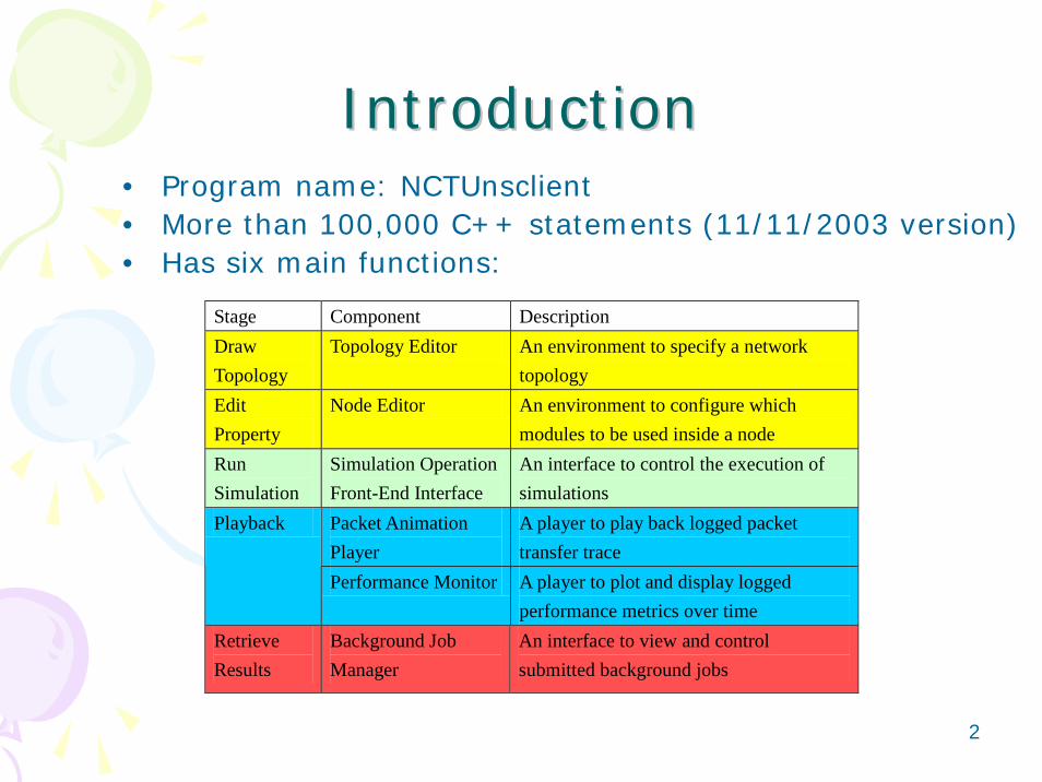
IntroductionIntroduction• Program name: NCTUnsclient• More than 100,000 C++ statements (11/11/2003 version)• Has six main functions:
Stage Component Description Draw Topology
Topology Editor An environment to specify a network topology
Edit Property
Node Editor An environment to configure which modules to be used inside a node
Run Simulation
Simulation Operation Front-End Interface
An interface to control the execution of simulations
Packet Animation Player
A player to play back logged packet transfer trace
Playback
Performance Monitor A player to plot and display logged performance metrics over time
Retrieve Results
Background Job Manager
An interface to view and control submitted background jobs
3
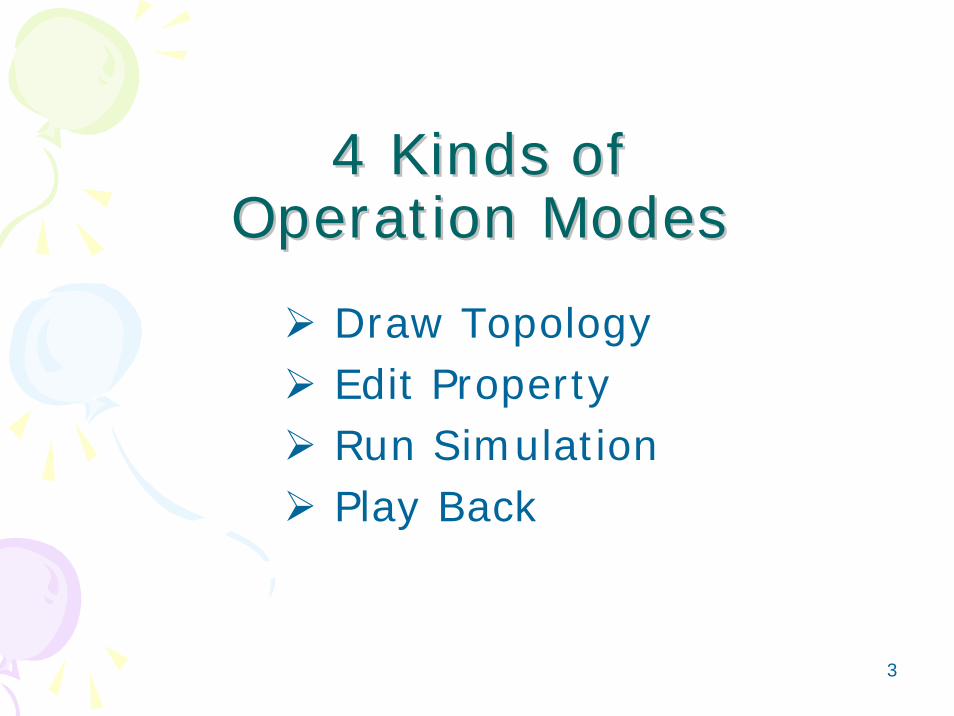
4 Kinds of 4 Kinds of Operation ModesOperation Modes
Draw TopologyEdit PropertyRun SimulationPlay Back

4
4 Kinds of 4 Kinds of Operation ModesOperation Modes
Draw TopologyEdit PropertyEdit PropertyEdit PropertyRun SimulationRun SimulationRun SimulationPlay BackPlay BackPlay Back

5
Topology Editor (T.E.)Topology Editor (T.E.)
Working Area
6
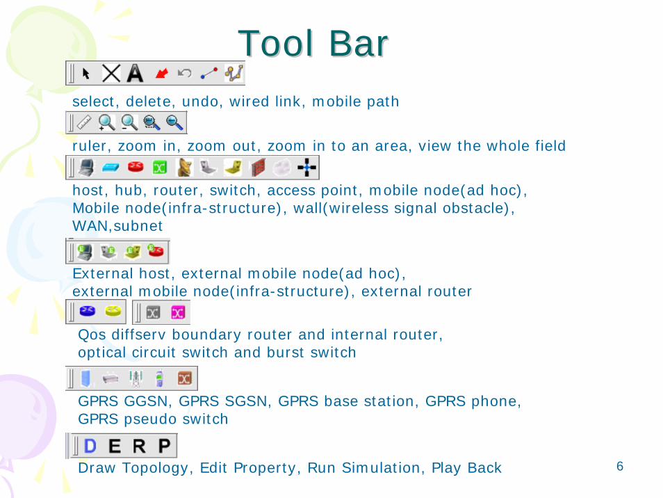
Tool BarTool Barselect, delete, undo, wired link, mobile path
ruler, zoom in, zoom out, zoom in to an area, view the whole field
Draw Topology, Edit Property, Run Simulation, Play Back
Qos diffserv boundary router and internal router, optical circuit switch and burst switch
GPRS GGSN, GPRS SGSN, GPRS base station, GPRS phone,GPRS pseudo switch
host, hub, router, switch, access point, mobile node(ad hoc),Mobile node(infra-structure), wall(wireless signal obstacle),WAN,subnet
External host, external mobile node(ad hoc), external mobile node(infra-structure), external router
7
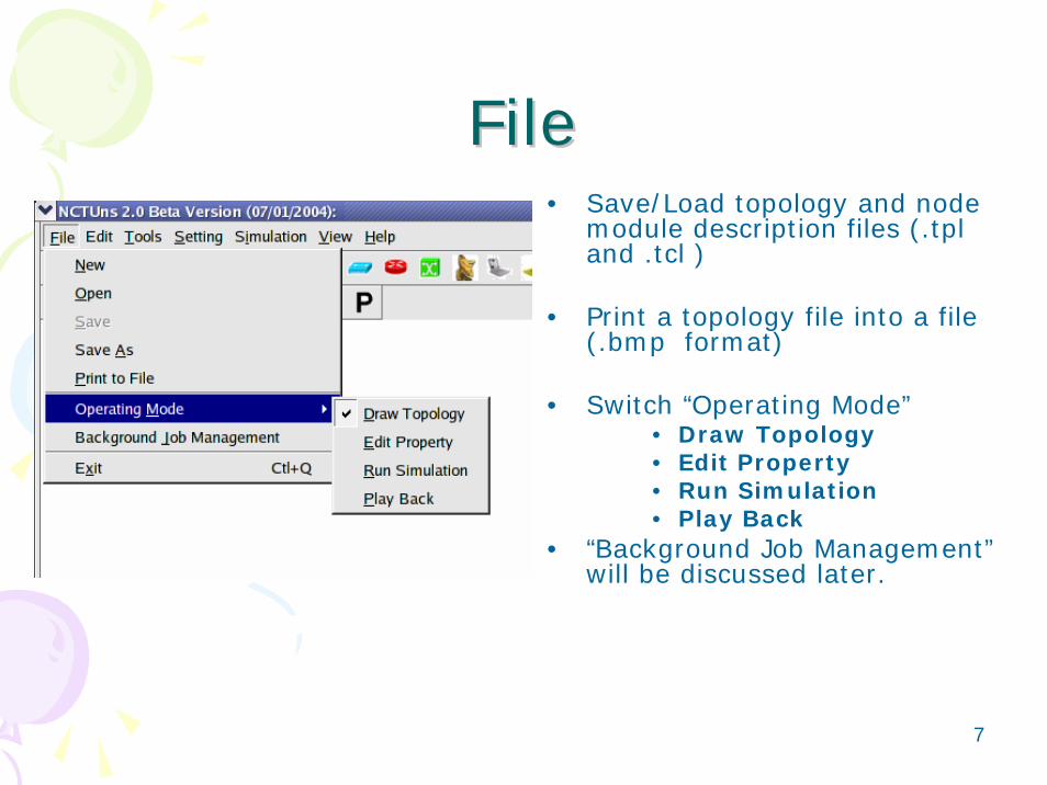
FileFile• Save/Load topology and node
module description files (.tpland .tcl )
• Print a topology file into a file (.bmp format)
• Switch “Operating Mode”• Draw Topology• Edit Property• Run Simulation• Play Back
• “Background Job Management”will be discussed later.

8
EditEdit

9
ToolsTools
• Mobile node related tools• Insert applications: import traffic
description file (.tfc )
10
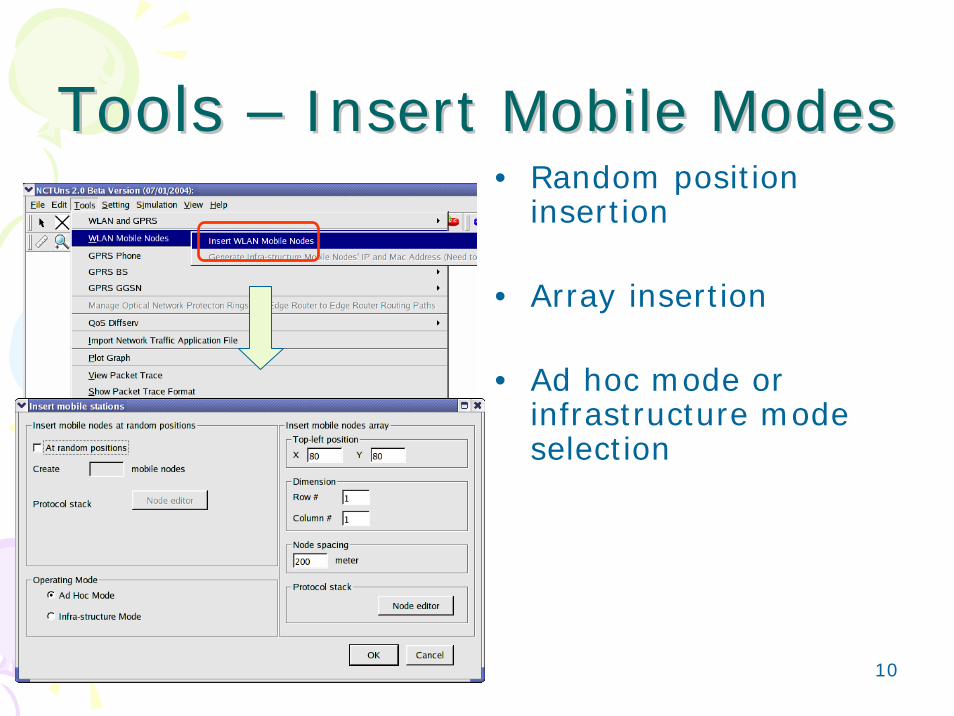
Tools Tools –– Insert Mobile ModesInsert Mobile Modes• Random position
insertion
• Array insertion
• Ad hoc mode or infrastructure mode selection

11
Tools Tools –– Import & Export mobile Import & Export mobile nodes from/to filesnodes from/to files
You can import/export mobile nodes files that you already specified.

12
Tools Tools —— Generate Random Generate Random WaypointsWaypoints
• Step by step generation
• Or automatic generation up to a specified time

13
Tools Tools –– Generate Infrastructure Generate Infrastructure NodeNode’’s IP and MAC Addresss IP and MAC Address
• A user should specify the subnet ID manually.
• The GUI will generate the IP andMAC addresses automatically.

14
Tools Tools –– Enter See Movement ModeEnter See Movement Mode
• step1 : enter see movement mode
• step2 :set display properties
• step3 :play

15
Tools Tools –– Generate Large Generate Large NetworkNetwork

16
Setting Setting –– Paste Background Paste Background GraphGraph

17
Setting Setting -- BackgroundBackground
Move and scale the graph
Set the scale of the map
Set the brightness of the graph

18
4 Kinds of 4 Kinds of Operation ModesOperation Modes
Draw TopologyDraw TopologyDraw TopologyEdit PropertyRun SimulationRun SimulationRun SimulationPlay BackPlay BackPlay Back

19
Edit Property ModeEdit Property Mode
The network node icons are disabled in this mode.

20
Host: Dialog BoxHost: Dialog Box
• Basic network node type
• Application setup
• Interface down time setting

21
Host: Setting ApplicationHost: Setting Application• Specify “Start
time” , “Stop time”
• Specify command string
• Specify absolute input file path and name

22
Host: Down TimeHost: Down Time
• Specify the down time periods of a node
23
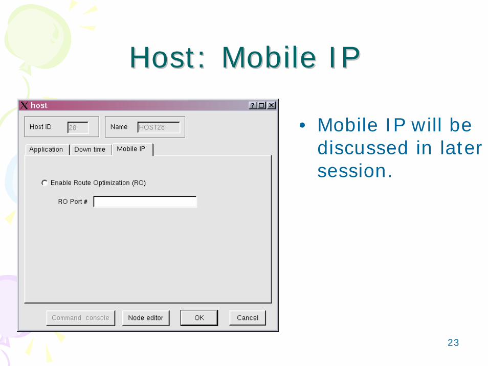
Host: Mobile IPHost: Mobile IP
• Mobile IP will be discussed in later session.

24
Hub: Dialog BoxHub: Dialog Box
• The bandwidth of the hub
• Down time setting

25
Switch: Dialog BoxSwitch: Dialog Box
• Down time setting

26
Router: Dialog Box Router: Dialog Box
• Select a method to compute routes– God route– Routing daemons
• Application • Down time
setting
27
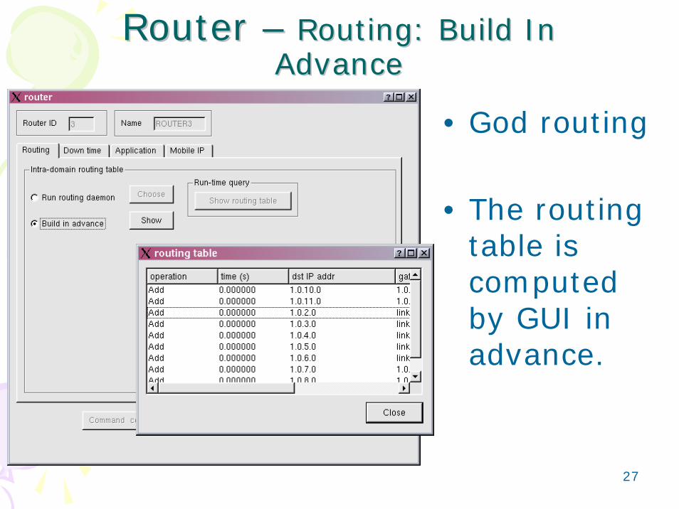
Router Router –– Routing: Build In Routing: Build In AdvanceAdvance
• God routing
• The routing table is computed by GUI in advance.
28
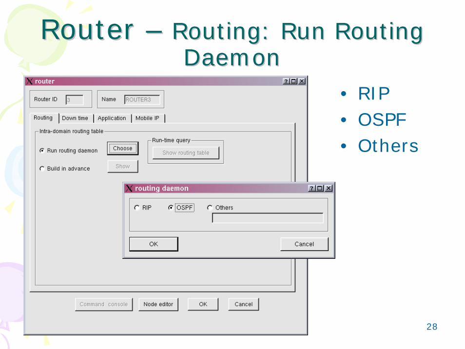
Router Router –– Routing: Run Routing Routing: Run Routing DaemonDaemon
• RIP• OSPF• Others

29
AP: Dialog BoxAP: Dialog Box
• Down time setting
30
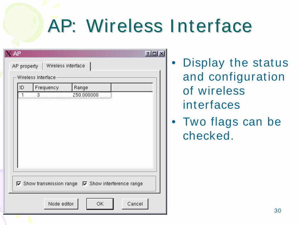
AP: Wireless InterfaceAP: Wireless Interface
• Display the status and configuration of wireless interfaces
• Two flags can be checked.

31
Mobile NodeMobile Node
• Moving path• Down time setting• Interface• Application• Single-hop
connectivity• Multi-hop
connectivity• Three flags

32
Mobile Node: Moving PathMobile Node: Moving Path’’s s Turning PointTurning Point

33
Tools Tools –– Generate Infrastructure Generate Infrastructure NodeNode’’s IP and MAC Addresss IP and MAC Address
• A user should specify the subnet ID manually.
• The GUI will generate the IP andMAC addresses automatically.

34
Mobile Node: Mobile Node: InterfaceInterface
• Display the info. of the attached wireless interfaces
• Configure the IP address of the default gateway (Infra-structure mode mobile node only)

35
M.N.: SingleM.N.: Single--hop Connectivityhop Connectivity
• Display single-hop connectivity/ disconnectivityevents according to the transmission range of M.N.

36
M.N.: MultiM.N.: Multi--hop Connectivityhop Connectivity
• Display multi-hop connectivity/ disconnectivityevents according to the transmission range of M.N.

37
Link: Dialog BoxLink: Dialog Box
• Propagation delay• Bandwidth• BER• Down time setting• Bi-direction
configuration
38
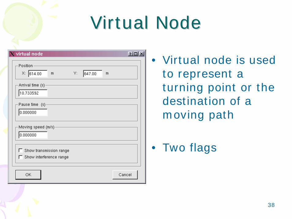
Virtual NodeVirtual Node
• Virtual node is used to represent a turning point or the destination of a moving path
• Two flags

39
Node EditorNode Editor
• Module groups• Protocol stack
display• Control buttons
– Specify– Delete– Redraw– Copy to all ports– Copy to all nodes
40
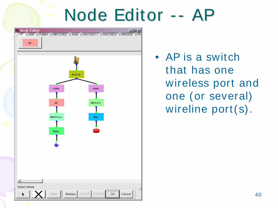
Node Editor Node Editor ---- APAP
• AP is a switch that has one wireless port and one (or several) wireline port(s).
41
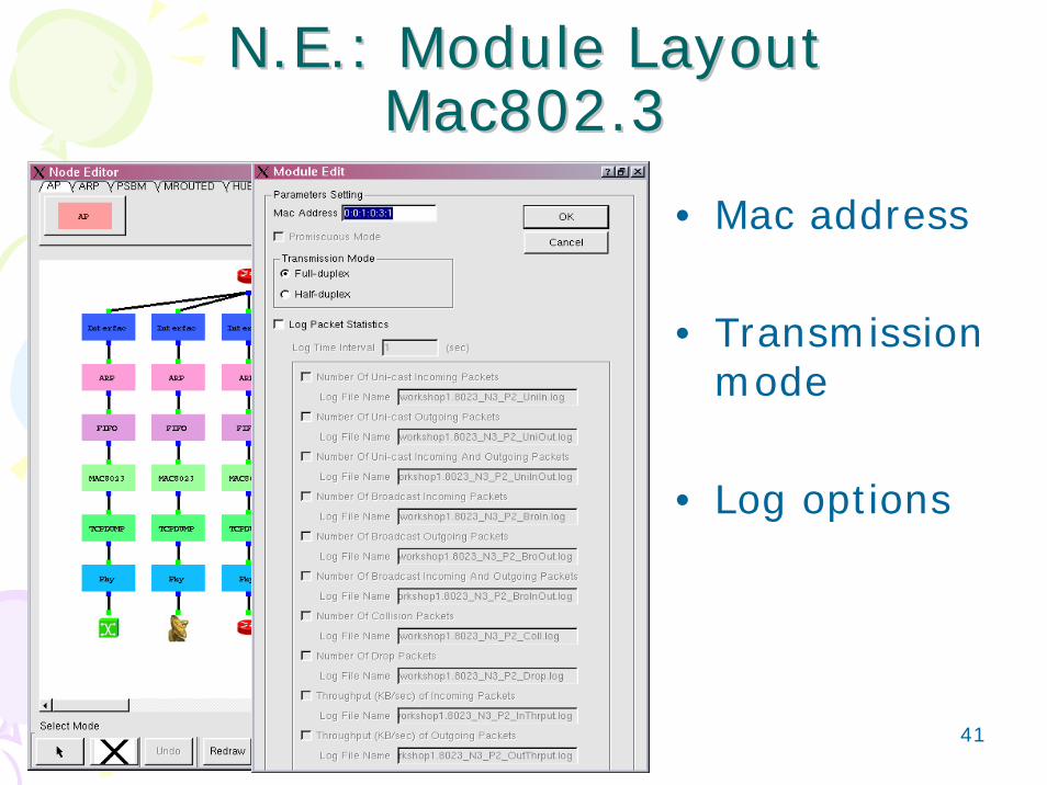
N.E.: Module LayoutN.E.: Module LayoutMac802.3Mac802.3
• Mac address
• Transmission mode
• Log options
42
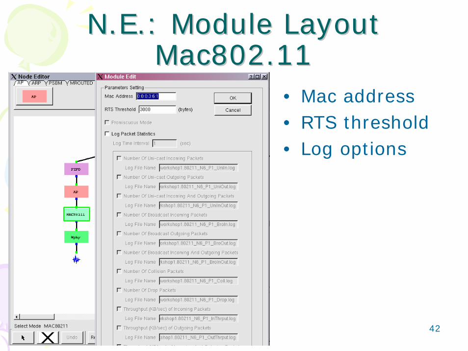
N.E.: Module LayoutN.E.: Module LayoutMac802.11Mac802.11
• Mac address• RTS threshold • Log options

43
N.E.: Module LayoutN.E.: Module LayoutInterfaceInterface
• IP address and network mask

44
N.E.: Module LayoutN.E.: Module LayoutARPARP
• Run ARP protocol– Flush time interval
• Know in advance

45
N.E.: Module LayoutN.E.: Module LayoutFIFOFIFO
• Maximum queue length
• Log options• Run-time query
panel

46
N.E.: Module LayoutN.E.: Module LayoutPHYPHY
• Display BW , BER and propagation delay
• Link failure option• See “Down Time
Setting” button
47
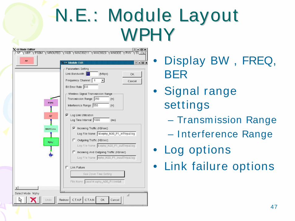
N.E.: Module LayoutN.E.: Module LayoutWPHYWPHY
• Display BW , FREQ, BER
• Signal range settings– Transmission Range – Interference Range
• Log options• Link failure options

48
N.E.: Module LayoutN.E.: Module LayoutAWPHYAWPHY
• Set BW , FREQ, BER
• Additional Noise• Transmit Power,
Antenna Gain• Transmission Rage
– By Distance/Receive Power Threshold

49
N.E.: Module LayoutN.E.: Module LayoutSwitchSwitch
• Learning bridge protocol– Spanning tree
protocol
• Know in advance• Run-Time query

50
Miscellaneous SettingsMiscellaneous Settings• Wireless Connectivity Color• Wireless Connectivity Speedup Factor• Wireless frame color

51
M.S.: Connectivity colorM.S.: Connectivity color
• Connectivity color:The color of connectivity indication line
• Used only in “Enter see movement mode”
52
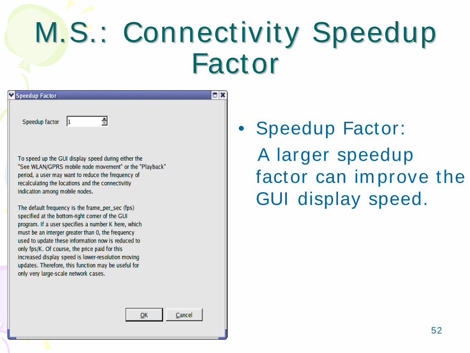
M.S.: Connectivity Speedup M.S.: Connectivity Speedup FactorFactor
• Speedup Factor:A larger speedup factor can improve the GUI display speed.

53
M.S.: Frame ColorM.S.: Frame Color• A user can specify
the colors for various wireless frames for each channel
• Font setting

54
4 Kinds of 4 Kinds of Operation ModesOperation Modes
Draw TopologyDraw TopologyDraw TopologyEdit PropertyEdit PropertyEdit PropertyRun SimulationPlay BackPlay BackPlay Back

55
Simulation Front End InterfaceSimulation Front End Interface
• Change to ‘Run Simulation’ mode• Two settings are required before a
simulation starts:1. Dispatcher 2. Simulation

56
S.F.E.I. S.F.E.I. –– Dispatcher SettingDispatcher Setting• Dispatcher IP
address and port #
• Login username and password
• Email address

57
S.F.E.I. S.F.E.I. –– Simulation SettingSimulation Setting• Field size and
simulation time• Enable/Disable
generate packet animation log file
• Simulation speed • GUI• System command
Note: This must be set in “Edit Property” mode.

58
S.F.E.I. S.F.E.I. –– Simulation Setting Simulation Setting ––SpeedSpeed
• Virtual clock granularity
• Two Simulation speed modes:– As fast as possible– As fast as the real-
world clock

59
S.F.E.I. S.F.E.I. –– Simulation Setting Simulation Setting ––GUIGUI
• Specify the proportion: how many meters per pixel (this option is disabled now)

60
S.F.E.I. S.F.E.I. –– Simulation Setting Simulation Setting ––System CommandSystem Command
• GET {nodeid} {portid}{module} {tag}
• SET {nodeid} {portid} {module} {tag} {value}
• GETALL {module} {tag}

61
S.F.E.I. S.F.E.I. –– Simulation Command 1Simulation Command 1--
• Run• Reconnect• Submit as
Background Job

62
S.F.E.I. S.F.E.I. –– Simulation Command 2Simulation Command 2--
During execution• Pause/Continue• Stop• Abort• Disconnect

63
S.F.E.I. S.F.E.I. –– Simulation Command 3Simulation Command 3--
• Disconnect – need to provide the dispatcher with a session name
• Reconnect –choose a session to resume based on the selected session name

64
S.F.E.I. S.F.E.I. –– Simulation Command 4Simulation Command 4--
• Submit – need to provide the dispatcher with a job name
• Backgraound Job Management – can get the progress of a job or reconnect to a job

65
4 Kinds of 4 Kinds of Operation ModesOperation Modes
Draw TopologyDraw TopologyDraw TopologyEdit PropertyEdit PropertyEdit PropertyRun SimulationRun SimulationRun SimulationPlay Back

66
Packet Animation PlayerPacket Animation Player• Player control panel / Display area

67
Packet Animation Player Packet Animation Player Control PanelControl Panel
• LCD: show the current time• Scroll bar: move the current time to a
desired time directly or show the progress• Time granularity: zoom in/out buttons• Play commands: play, stop, pause, step
forward, step backward• Time granularity zoom in/out list

68
Packet Animation Player Packet Animation Player Display AreaDisplay Area
• The lightened link indicates there is a packet.
• A colored line with an arrow represents a packet.
• Different kinds of packets are represented in different colors.

69
Performance Monitor 1Performance Monitor 1--
Double-clicking “Graph 0” can let you change the label and color ofthe performance curve.

70
Performance Monitor 2Performance Monitor 2--

71
View packet traceView packet trace
• “View Packet Trace”will convert a ptr log file into a readable format.
• “Show Packet Trace Format” will show how to read the packet trace.
72
Thank YouThank You
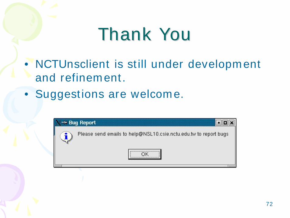
• NCTUnsclient is still under development and refinement.
• Suggestions are welcome.