a guide to rs-232 communication with fx plcs - mitsubishi plc fx-232adp rs... · mitsubishi...
TRANSCRIPT

TECHNOLOGY FOR LIFEIssued by: Mitsubishi Electric Europe B.V. - UK BranchDocument issue: Ver B, August 1998Produced by : - Customer Technology Centre (UK) (CTC UK)Travellers Lane, Hatfield, Herts, AL10 8XB, UKAuthor: Alex Kew
MITSUBISHIELECTRIC
Page 1 of 35
A GUIDE TO RS-232 COMMUNICATIONWITH FX PLCS

TECHNOLOGY FOR LIFEIssued by: Mitsubishi Electric Europe B.V. - UK BranchDocument issue: Ver B, August 1998Produced by : - Customer Technology Centre (UK) (CTC UK)Travellers Lane, Hatfield, Herts, AL10 8XB, UKAuthor: Alex Kew
MITSUBISHIELECTRIC
CTC-FX RS-232 COMMS Page 2 of 35
A GUIDE TO RS-232 COMMUNICATION WITH FX PLCS
This document has been written specifically for FX and FX0N users that are unfamiliarwith RS-232 ‘no-protocol’ communication and would like to gain more understanding ofwhat the function is and how it works. The aim of this document is not to be tootechnical, but to give explanations and examples1 of key points where ever possible sothat the reader can use the FX range in their own RS-232 system.
The intention is not to replace any of the associated manuals, such as the FXProgramming Manual, or the FX-232ADP / FX0N-232ADP User Guides, but to backthem up in learning how to use the function.
1 Disclaimer:
All examples and diagrams in this document are included to aid the readers’understanding of the text. Mitsubishi Electric does not claim that these examples anddiagrams are correct and error free, and will not accept responsibility for anyconsequential damage that may occur as a result of the installation and programming ofthe equipment associated with this document.

TECHNOLOGY FOR LIFEIssued by: Mitsubishi Electric Europe B.V. - UK BranchDocument issue: Ver B, August 1998Produced by : - Customer Technology Centre (UK) (CTC UK)Travellers Lane, Hatfield, Herts, AL10 8XB, UKAuthor: Alex Kew
MITSUBISHIELECTRIC
CTC-FX RS-232 COMMS Page 3 of 35
Contents
1. INTRODUCTION TO SERIAL COMMUNICATION 5
1.1 WHAT IS SERIAL COMMUNICATION? 5
1.2 TYPES OF SERIAL COMMUNICATION SYSTEM 51.2.1 Simplex 51.2.2 Half-duplex 51.2.3 Full-duplex 5
1.3 TYPES OF TRANSMISSION 61.3.1 Synchronous Transmission 61.3.2 Asynchronous Transmission 6
1.4 WHAT IS RS-232? 61.4.1 Physical interface definition 61.4.2 Electrical interface definition 7
1.5 CONFIGURING COMMUNICATION 71.5.1 Data length 71.5.2 Baud rate 71.5.3 Start bit 81.5.4 Stop bit/s 81.5.5 Parity bit 8
1.6 HANDSHAKING 81.6.1 Software handshaking 81.6.2 Hardware handshaking 8
1.7 SUMMARY 9
2. OVERVIEW OF SERIAL COMMUNICATION WITH THE FX PLC 10
2.1 FX-232ADP - RS-232 ADAPTER 10
2.2 USER DEFINED ‘NO-PROTOCOL’ COMMUNICATION 11
3. CREATING THE SERIAL COMMUNICATION PROGRAM 12
3.1 DATA STORAGE FORMAT 12
3.2 SET COMMUNICATION PARAMETERS 133.2.1 Parameter set up example 143.2.2 Header and terminator characters 143.2.3 Hardware handshaking types 14
3.3 THE RS INSTRUCTION 15

TECHNOLOGY FOR LIFEIssued by: Mitsubishi Electric Europe B.V. - UK BranchDocument issue: Ver B, August 1998Produced by : - Customer Technology Centre (UK) (CTC UK)Travellers Lane, Hatfield, Herts, AL10 8XB, UKAuthor: Alex Kew
MITSUBISHIELECTRIC
CTC-FX RS-232 COMMS Page 4 of 35
3.4 SET TRANSMIT MESSAGE 15
3.5 PROCESS RECEIVED MESSAGE 15
4. POINTS TO NOTE ABOUT FX SERIAL COMMUNICATION 16
5. APPLICATION EXAMPLES 17
5.1 SENDING MESSAGES TO A PRINTER WITH THE FX 17
5.2 SENDING AND RECEIVING DATA TO/FROM A PC 20
5.3 PRINTING REAL TIME CLOCK (RTC) DATA - USING THE ASCI INSTRUCTION(FNC 82) 23
5.4 READING BAR CODES 29
Appendix 1 - Standard ASCII character set 33
Appendix 2 - converting 25 pin to 9 pin connectors 33
Appendix 3 - Timing Chart For Handshaking Methods 34
Appendix 4 - Further Reading 34
Notes

TECHNOLOGY FOR LIFEIssued by: Mitsubishi Electric Europe B.V. - UK BranchDocument issue: Ver B, August 1998Produced by : - Customer Technology Centre (UK) (CTC UK)Travellers Lane, Hatfield, Herts, AL10 8XB, UKAuthor: Alex Kew
MITSUBISHIELECTRIC
CTC-FX RS-232 COMMS Page 5 of 35
1. INTRODUCTION TO SERIAL COMMUNICATION
This chapter introduces the concept of a serial communication system, and describesthe RS-232 serial communication standard.
1.1 WHAT IS SERIAL COMMUNICATION?
Serial communication is the transfer of binary data (a series of 0’s and 1’s) through asingle channel. Most devices like printers, computers, bar code readers, etc have aserial port by which they can be connected to another device with a serial port and thetwo devices can send and receive character or bit based data to each other.
A basic serial communication system is shown below, with one device sending data tothe other.
Device 2Device 1
RD
SGSG
RD
SDSD
Serial PortSerial Port
(Transmitter) (Receiver)
Data Flow
10010010
Figure 1-1 Basic serial communication system
Data is transmitted through SD (Send Data) of the transmitter, and received through RD(Receive Data) of the receiver. The voltage signals are relative to SG (Signal Ground).
1.2 TYPES OF SERIAL COMMUNICATION SYSTEM
Depending on the nature of the devices in the system, data will flow in a certaindirection at a certain time. This section overviews the main types of serialcommunication.
1.2.1 SimplexThis describes a system where data flows in one direction only, such as a bar codereader connected to a terminal.
1.2.2 Half-duplexThis describes a system where data can flow in each direction, but only one way at atime. An example of a half-duplex system is a computer connected to a dot-matrixprinter.
1.2.3 Full-duplexThis describes a system where data flows in each direction, both ways at the sametime.An example of a full-duplex system is two computers connected to each other.

TECHNOLOGY FOR LIFEIssued by: Mitsubishi Electric Europe B.V. - UK BranchDocument issue: Ver B, August 1998Produced by : - Customer Technology Centre (UK) (CTC UK)Travellers Lane, Hatfield, Herts, AL10 8XB, UKAuthor: Alex Kew
MITSUBISHIELECTRIC
CTC-FX RS-232 COMMS Page 6 of 35
1.3 TYPES OF TRANSMISSION
There are two types of transmission; synchronous and asynchronous.
1.3.1 Synchronous TransmissionThe transmitted data contains clock information that is used to synchronise thecommunication at both devices. This means that transmission overheads (i.e. start/stopbits) can be greatly reduced, as the transmission occurs at a specific time determinedby the clock.
1.3.2 Asynchronous TransmissionThe transmitted data does not contain clock information, and the receiver knows onlythe approximate speed of the transmission. Because the communication is notsynchronised by a common clock signal, extra bits are required to signify the start andend of each character. These are called, unsurprisingly, the start bit and the stop bit.
This document will deal mainly with the asynchronous method, as it is the method usedby the FX PLC.
1.4 WHAT IS RS-232?
RS-232 is the most common of the standards defining the physical and electricalinterface of a serial port.
1.4.1 Physical interface definitionThe physical interface defines the layout of the port and cable type. Below is the pinconfiguration for the 25-pin RS-232 port (there is also a 9-pin port). The maximum cablelength is 15m.
25
14
13
20
12345678
FG: Frame GroundSD: Send DataRD: Rece ive DataRTS: Reques t To Send
DSR: Data Set ReadySG: S igna l GroundCD: Carr ier Detect
DTR: Data Termina l Ready
CTS: C lear To Send
Figure 1-2 25-pin RS-232 port

TECHNOLOGY FOR LIFEIssued by: Mitsubishi Electric Europe B.V. - UK BranchDocument issue: Ver B, August 1998Produced by : - Customer Technology Centre (UK) (CTC UK)Travellers Lane, Hatfield, Herts, AL10 8XB, UKAuthor: Alex Kew
MITSUBISHIELECTRIC
CTC-FX RS-232 COMMS Page 7 of 35
The following table describes the operation of the signal pins of the RS-232 port.
1.4.2 Electrical interface definitionThe electrical interface defines the voltage levels used to represent the 1s and 0s whichmake up the data.
For logic 0: +3 to +12VFor logic 1: -3 to -12V
(To allow for any noise in the channel, voltage signals between -3 to +3V are ignored.)
1.5 CONFIGURING COMMUNICATION
Both devices in a serial communications system need to be configured with the samecommunication parameters so that data flows effectively. This section will explain eachparameter.
1.5.1 Data lengthTransferred data is usually characters in an asynchronous transmission system. In mostcases, these characters are in ASCII (American Standard Code for InformationInterchange) format. The ASCII character set includes all the letters of the alphabet(upper and lower case), numbers 0 to 9, and other symbols such as +, =, % and so on(see Appendix 1 for the standard ASCII set).
Each ASCII character is encoded as a binary number so they can be tranmsittedthrough the serial channel. The number of bits that make up this binary number isreferred to as the data length, and can be set as 7 bits or 8 bits.
When the standard ASCII set is used, the most significant bit in the number isredundant. So, by setting the data length as 7 bits, transmission overheads can bereduced (especially when lots of data needs to be transferred).
1.5.2 Baud rateThe baud rate is the speed of transmission, given in bits per second (bps). The baudrate can be set between 300 and 19200 bps.
Pin Signal Description
1 FG Frame Ground Used to provide grounding for the cable2 SD Send Data Used to send data to the other device3 RD Receive Data Used to receive data from the other device4 RTS Ready To Send Indicates the device has data it wants to send5 CTS Clear To Send Indicates the other device is ready to receive data6 DSR Data Set Ready Indicates the other device is ready to receive data7 SG Signal Ground All signals sent or received are relative to this pin8 CD Carrier Detect Indicates that the carrier for transmission is on
20 DTR Data Terminal Ready Indicates the device has data it wants to send

TECHNOLOGY FOR LIFEIssued by: Mitsubishi Electric Europe B.V. - UK BranchDocument issue: Ver B, August 1998Produced by : - Customer Technology Centre (UK) (CTC UK)Travellers Lane, Hatfield, Herts, AL10 8XB, UKAuthor: Alex Kew
MITSUBISHIELECTRIC
CTC-FX RS-232 COMMS Page 8 of 35
1.5.3 Start bitThe start bit, usually a 1, signifies the beginning of a character to the receiving device inan asynchronous system. This parameter is not usually configurable by the user.
1.5.4 Stop bit/sEither one or two stop bits, usually a 0, is used to signify the end of a character in anasynchronous system. The user can choose whether one or two stop bits is added.
1.5.5 Parity bitParity is used as a simple method of error checking. The parity bit is used to make thenumber of 1s and 0s in the character either odd or even. This is illustrated below.
Parity bit (even) Parity bit (odd)1 0 1 0 1 1 0 0 1
1 1 1 0 1 0 1 1 0
The idea is that if the parity is set, say to even for example, but the receiver counts anodd number of 1s, then it assumes that a bit is in error.
1.6 HANDSHAKING
Handshaking is a term which is used to describe how the flow of data is controlled byeach of the devices in the system. There are two main methods; software andhardware.
1.6.1 Software handshakingThis takes place using certain control characters, such as XON / XOFF, which are sentbetween the devices to tell each other to begin or stop sending data.
A good example of this method is a laser-jet printer connected to a computer. When theprinter buffer is empty, the printer sends XON to the computer. The computer will thenstart to send data to be printed. If the printer buffer becomes full, the printer sendsXOFF, and the computer stops transmitting.
Other methods of software handshaking include the ENQ / ACK method, where thetransmitter sends an ENQ (enquiry) command at the start of a frame (severalcharacters grouped together), and the receiver sends back an ACK (acknowledge) toindicate the frame was received correctly. If a NAK (not acknowledge) is sent backinstead, the transmitter resends the frame.
1.6.2 Hardware handshakingThis occurs using dedicated signal lines DSR & DTR and/or RTS & CTS within theserial port of the devices. DSR & DTR are perhaps more commonly used as thehandshaking lines, as RTS & CTS are gradually being phased out in most systems.
When hardware handshaking is used, the DTRs and DSRs are connected together, asshown in the example RS-232 cable in Figure 1-3, known as a null modem.

TECHNOLOGY FOR LIFEIssued by: Mitsubishi Electric Europe B.V. - UK BranchDocument issue: Ver B, August 1998Produced by : - Customer Technology Centre (UK) (CTC UK)Travellers Lane, Hatfield, Herts, AL10 8XB, UKAuthor: Alex Kew
MITSUBISHIELECTRIC
CTC-FX RS-232 COMMS Page 9 of 35
Figure 1-3 Examplenull modem cable
Normally, when a device has data it wants to transmit it turns on its DTR pin. Thereceiver then knows that the transmitter wants to send data, so when it is ready it alsoturns on its DTR pin. When the transmitter sees that its own DSR pin has come on, itwill transmit. When the transmission has finished, the transmitter turns off its DTR to tellthe receiver that no more data is pending. The receiver turns off its DTR, and thesystem is ready to begin again.
1.7 SUMMARY
A serial communication system transfers character or bit based data sequentially, onebit after the other, through a single channel.
The three types of serial system are simplex (one way only), half-duplex (two ways butone way at a time) and full-duplex (two ways simultaneously).
RS-232 is one of the standards for a serial port, and is perhaps the most common. Theconfiguration is a 25-pin ‘D’ type port, but 9-pin ‘D’ type ports are also available (asmany of the signal pins are unused in the 25-pin port). The RS-232 standard supportsasynchronous communication (transmission is not synchronised by a clock signal, soextra bits are added to each character to signify their start and end).
Communication parameters, such as data length, baud rate, stop bits and parity areconfigurable by the user. Their settings are dependant on the setting requirements ofthe communication devices in the system.
Flow control is acheived using handshaking, either software or hardware orientated.With software handshaking, transfer of special characters controls the flow of data.With hardware handshaking, dedicated signal lines within the serial channel are used.
12345678
20
12345678
20
FGSDRDRTSCTSDSRSGCDDTR
FGSDRD
RTSCTSDSR
SGCD
DTR

TECHNOLOGY FOR LIFEIssued by: Mitsubishi Electric Europe B.V. - UK BranchDocument issue: Ver B, August 1998Produced by : - Customer Technology Centre (UK) (CTC UK)Travellers Lane, Hatfield, Herts, AL10 8XB, UKAuthor: Alex Kew
MITSUBISHIELECTRIC
CTC-FX RS-232 COMMS Page 10 of 35
2. OVERVIEW OF SERIAL COMMUNICATION WITH THE FX PLC
FX PLCs from version 3.30, and all FX0N versions, can be used as an asynchronoustransmitter and/or receiver in an RS-232 serial communication system. The RSinstruction defines message areas, and the FX-232ADP module provides the RS-232port for the FX base unit; with the FX0N-232ADP for FX0N base units. To allow theuser control of data transfer, some special auxilliary relays (M-coils) have beenincluded. This chapter overviews how communication is acheived. More detail can befound in the next chapter.
2.1 FX-232ADP - RS-232 ADAPTER
Using the RS-232 adapter, the FX-232ADP, the FX PLC can be used to send andreceive ASCII character or bit data in a serial communication system. The FX-232ADPcan be seen below.
Figure 2-1 The FX-232ADP RS-232 adapter module for FX PLCs
The module plugs into the communication port on the left hand side of the FX base unit.The pin out is the same as the ‘standard’ pin out that is shown in Figure 1-2 on page 5.The FX0N-232ADP is the FX0N equivalent to this module.

TECHNOLOGY FOR LIFEIssued by: Mitsubishi Electric Europe B.V. - UK BranchDocument issue: Ver B, August 1998Produced by : - Customer Technology Centre (UK) (CTC UK)Travellers Lane, Hatfield, Herts, AL10 8XB, UKAuthor: Alex Kew
MITSUBISHIELECTRIC
CTC-FX RS-232 COMMS Page 11 of 35
2.2 USER DEFINED ‘NO-PROTOCOL’ COMMUNICATION
What makes using serial communication with the FX range so flexible is that it does notuse a specific protocol* or port setting. The user has the freedom to create messageframes within the sequence program, and set the communication parameters in aspecial data register. Hence the FX can be made to match the protocol and port settingof virtually any other RS-232 device.
The next chapter details how the user can set up and use the serial communicationfunction.
* Protocols define the communication structure necessary for succesful data transfer,i.e. frame format (character sequence) and handshaking method.

TECHNOLOGY FOR LIFEIssued by: Mitsubishi Electric Europe B.V. - UK BranchDocument issue: Ver B, August 1998Produced by : - Customer Technology Centre (UK) (CTC UK)Travellers Lane, Hatfield, Herts, AL10 8XB, UKAuthor: Alex Kew
MITSUBISHIELECTRIC
CTC-FX RS-232 COMMS Page 12 of 35
3. CREATING THE SERIAL COMMUNICATION PROGRAM
The basic format of the serial communication sequence program is shown in Figure 3-1below. Explanations of each main stage follow.
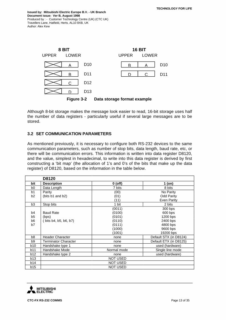
3.1 DATA STORAGE FORMAT
The data storage format refers to whether one or two ASCII characters is held in asingle 16-bit data register.
The flag M8161 is used to set the format; ON for 8-bit storage (one character), OFF for16-bit storage (two characters). When 8-bit storage is selected, only the lower 8 bits of16-bit data registers are used to hold data. The upper 8 bits are not used. If 16-bit isselected, then all 16 bits of data registers are used to hold data.
Figure 3-2 illustrates 8-bit and 16-bit data storage of ASCII characters A B C D, inregisters starting at D10 :
M8161SET
M8002
1
SET TRANSMIT MESSAGE
M8122SET
PROCESS RECEIVED MESSAGEM8123
M8123RST
D200K4D100RS K10
5
4
3
2 H78FMOV D8120
Figure 3-1 Basic format of sequence program
TECHNOLOGY FOR LIFEIssued by: Mitsubishi Electric Europe B.V. - UK BranchDocument issue: Ver B, August 1998Produced by : - Customer Technology Centre (UK) (CTC UK)Travellers Lane, Hatfield, Herts, AL10 8XB, UKAuthor: Alex Kew
MITSUBISHIELECTRIC
CTC-FX RS-232 COMMS Page 13 of 35
Although 8-bit storage makes the message look easier to read, 16-bit storage uses halfthe number of data registers - particularly useful if several large messages are to bestored.
3.2 SET COMMUNICATION PARAMETERS
As mentioned previously, it is necessary to configure both RS-232 devices to the samecommunication parameters, such as number of stop bits, data length, baud rate, etc, orthere will be communication errors. This information is written into data register D8120,and the value, simplest in hexadecimal, to write into this data register is derived by firstconstructing a ‘bit map’ (the allocation of 1’s and 0’s of the bits that make up the dataregister) of D8120, based on the information in the table below.
D8120bit Description 0 (off) 1 (on)b0 Data Length 7 bits 8 bitsb1 Parity (00) No Parityb2 (bits b1 and b2) (01)
(11)Odd ParityEven Parity
b3 Stop bits 1 bit 2 bits(0011) 300 bps
b4 Baud Rate (0100) 600 bpsb5 (bps) (0101) 1200 bpsb6b7
( bits b4, b5, b6, b7) (0110)(0111)(1000)(1001)
2400 bps4800 bps9600 bps19200 bps
b8 Header Character none Default STX (in D8124)b9 Terminator Character none Default ETX (in D8125)b10 Handshake type 1 none used (hardware)b11 Handshake Mode Normal mode Single line modeb12 Handshake type 2 none used (hardware)b13 NOT USEDb14 NOT USEDb15 NOT USED
A
B
LOWERUPPER
D10
D11
C
D
D12
D13
AB
CD
LOWERUPPER
D10
D11
16 BIT8 BIT
Figure 3-2 Data storage format example

TECHNOLOGY FOR LIFEIssued by: Mitsubishi Electric Europe B.V. - UK BranchDocument issue: Ver B, August 1998Produced by : - Customer Technology Centre (UK) (CTC UK)Travellers Lane, Hatfield, Herts, AL10 8XB, UKAuthor: Alex Kew
MITSUBISHIELECTRIC
CTC-FX RS-232 COMMS Page 14 of 35
3.2.1 Parameter set up exampleTo set into the FX the following communication parameters:
Data Length: 8 bitsParity: EvenBaud rate: 9,600 bpsHeader: UsedTerminator: UsedHandshake: type 1Handshake Mode: Ordinary
The bit map would be: 0 0 0 0 0 1 1 1 1 0 0 0 1 1 1 1 = 078F (hex)
As the ladder diagram in Figure 3-1 on page 12shows, this can be written into D8120using the MOV instruction.
3.2.2 Header and terminator charactersBits b8 and b9 can be used to attach predefined characters automatically to the startand end of a message. These characters are the header and terminator respectively.The header is written to D8124, and the terminator to D8125. Both are user definable,and the defaults are STX (start of text) and ETX (end of text).
3.2.3 Hardware handshaking typesThere are two types of hardware handshaking available, both using DSR and DTR.Only one may be selected at a time. The difference between the two types is the timingof how long the DSR and DTR lines are high (on) and low (off). Refer to the timingdiagram in Appendix 3.
b0b15 D8120
TECHNOLOGY FOR LIFEIssued by: Mitsubishi Electric Europe B.V. - UK BranchDocument issue: Ver B, August 1998Produced by : - Customer Technology Centre (UK) (CTC UK)Travellers Lane, Hatfield, Herts, AL10 8XB, UKAuthor: Alex Kew
MITSUBISHIELECTRIC
CTC-FX RS-232 COMMS Page 15 of 35
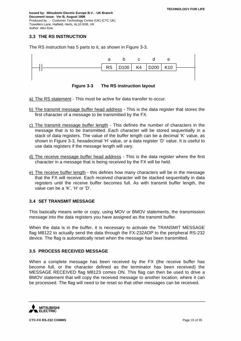
3.3 THE RS INSTRUCTION
The RS instruction has 5 parts to it, as shown in Figure 3-3.
a) The RS statement - This must be active for data transfer to occur. b) The transmit message buffer head address - This is the data register that stores the
first character of a message to be transmitted by the FX. c) The transmit message buffer length - This defines the number of characters in the
message that is to be transmitted. Each character will be stored sequentially in astack of data registers. The value of the buffer length can be a decimal ‘K’ value, asshown in Figure 3-3, hexadecimal ‘H’ value, or a data register ‘D’ value. It is useful touse data registers if the message length will vary.
d) The receive message buffer head address - This is the data register where the first
character in a message that is being received by the FX will be held. e) The receive buffer length - this defines how many characters will be in the message
that the FX will receive. Each received character will be stacked sequentially in dataregisters until the receive buffer becomes full. As with transmit buffer length, thevalue can be a ‘K’, ‘H’ or ‘D’.
3.4 SET TRANSMIT MESSAGE
This basically means write or copy, using MOV or BMOV statements, the transmissionmessage into the data registers you have assigned as the transmit buffer.
When the data is in the buffer, it is necessary to activate the TRANSMIT MESSAGEflag M8122 to actually send the data through the FX-232ADP to the peripheral RS-232device. The flag is automatically reset when the message has been transmitted.
3.5 PROCESS RECEIVED MESSAGE
When a complete message has been received by the FX (the receive buffer hasbecome full, or the character defined as the terminator has been received) theMESSAGE RECEIVED flag M8123 comes ON. This flag can then be used to drive aBMOV statement that will copy the received message to another location, where it canbe processed. The flag will need to be reset so that other messages can be received.
D200K4D100RS K10
dcba e
Figure 3-3 The RS instruction layout

TECHNOLOGY FOR LIFEIssued by: Mitsubishi Electric Europe B.V. - UK BranchDocument issue: Ver B, August 1998Produced by : - Customer Technology Centre (UK) (CTC UK)Travellers Lane, Hatfield, Herts, AL10 8XB, UKAuthor: Alex Kew
MITSUBISHIELECTRIC
CTC-FX RS-232 COMMS Page 16 of 35
4. POINTS TO NOTE ABOUT FX SERIAL COMMUNICATION
• The FX-232ADP can only be used to transfer data through the communication port(on the left hand side of the FX base unit), and is used in conjunction with the RSinstruction. It cannot be used to access, transfer or edit ladder program.
• The programming port is left free when using the FX-232ADP, allowing programming
tools, MMI’s, etc to still be connected. • Modem connection is made easier by automatic use of the CD (Carrier Detect) line.
This basically means that when the FX is dialling out through a modem, it will be ableto detect when the telephone-line connection has been made (M8124 comes ON).This is feature with the FX only, not FX0N.
• If more than one message is to be transfered, separate RS instructions are needed
for each message. Only one RS instruction may be active at a time. • To supplement the RS instruction, there are instructions to calculate sum check
code** (CCD instruction), convert ASCII characters to hexadecimal digits (HEXinstruction), and convert hexadecimal digits to ASCII characters (ASCI instruction).
More information on these instructions can be found in the FX Programming Manual. • If headers and/or terminators are selected, these are automatically added to a
message by the FX. • When using 16-bit operation, the data in the lower half of each data register is sent
first. • 16 bit operation means that half as many data registers are used for the transmit
and/or receive buffers.
** Sum checking is a method of error detection. A sum check code is calculated by summing thehexadecimal values of each character in the message frame, within the sum check range. Thetransmitting device calculates the sum check code, and adds it to the end of the data. Thereceiving device will perform a sum check of the received data, and if its sum check code isdifferent, it will signify an error.

TECHNOLOGY FOR LIFEIssued by: Mitsubishi Electric Europe B.V. - UK BranchDocument issue: Ver B, August 1998Produced by : - Customer Technology Centre (UK) (CTC UK)Travellers Lane, Hatfield, Herts, AL10 8XB, UKAuthor: Alex Kew
MITSUBISHIELECTRIC
CTC-FX RS-232 COMMS Page 17 of 35
5. APPLICATION EXAMPLES
This chapter includes some suggested applications examples for FX serialcommunication. All the hardware, and software information is given and it is intendedthat the examples are used as a guide to producing your own serial communicationsystem.
5.1 SENDING MESSAGES TO A PRINTER WITH THE FX
The FX can be connected to a printer, to print a brief report or a message whenever it isnecessary, such as error reports or production quotas, etc.
The example set up is as shown below:
*The pin configuration for F2-232CAB is:
25 pin D 25 pin Dmale male
1 12 23 34 45 56 67 78 820 20
To print a simple message
In the following example, the message “TEST OK” will be printed whenever X1 isactivated. The ladder program into the PLC would therefore be:
FX
PRINTER -Epson MX-80:
Baud - 9600Data bits - 8Stop bits - 1Parity - None
F2-232CABor equivalent*
FX-232ADP
FGSDRD
RTSCTSDSR
SGCD
DTR
FGSDRDRTSCTSDSRSGCDDTR
D8120 in the PLC needs to set as:bit bit15 14 13 12 11 10 9 8 7 6 5 4 3 2 1 0
0 0 0 0 0 0 0 0 1 0 0 0 0 0 0 1 0 0 8 1 hex

TECHNOLOGY FOR LIFEIssued by: Mitsubishi Electric Europe B.V. - UK BranchDocument issue: Ver B, August 1998Produced by : - Customer Technology Centre (UK) (CTC UK)Travellers Lane, Hatfield, Herts, AL10 8XB, UKAuthor: Alex Kew
MITSUBISHIELECTRIC
CTC-FX RS-232 COMMS Page 18 of 35
How it works
When the PLC and printer are powered up and connected as shown in the diagram onthe previous page, with the printer on-line and the PLC set to RUN, the message will besent if the RS instruction is activated and the transmit flag is ON. In the example, X0drives the RS instruction, and X1 pulses M0, which writes the message “TEST OK” intothe message area, as defined in the RS instruction parameters (D200 - D208). M0 alsosets M8122, thus sending the message. M8122 is automatically reset when the datahas been sent, so the message will be sent to the printer every time X1 is triggered.
SET M8161
MOV H0081
M8000
M8002
X0
X1
D8120
RS D200 K9 K0D209
M0PLS
M0MOV H0054 D200
MOV H0045 D201
MOV H0053 D202
MOV H0054 D203
MOV H0020 D204
MOV H004F D205
Handled by 8-bit data (uses thelower half of message registers)
Sets the comms parameters, asdescribed previously
The RS instruction (fnc 80) and itsparameters. Activated by X0
T
E
S
T
SP
Writes thedata to be sentinto the transmitbuffer area. Thehex datarepresents anASCII characterwhich the printerwill print. Seethe table ofASCII characterset in theappendix at theend of thisdocument.
MOV H004B D206
MOV H000D D207
MOV H000A D208
SET M8122
LF
CR
K
O
Set Transmitflag -i.e. senddata to printer
Note that CR(carriage return)and LF (line feed)are used. Theprinter movesdown one lineafter eachmessage
END

TECHNOLOGY FOR LIFEIssued by: Mitsubishi Electric Europe B.V. - UK BranchDocument issue: Ver B, August 1998Produced by : - Customer Technology Centre (UK) (CTC UK)Travellers Lane, Hatfield, Herts, AL10 8XB, UKAuthor: Alex Kew
MITSUBISHIELECTRIC
CTC-FX RS-232 COMMS Page 19 of 35
Creating your own messages
Any message is a group of ASCII characters. The ASCII character set includes all theletters of the alphabet, upper and lower case, and all numbers 0-9 and most symbols. Inthe example given, the message ‘TEST OK’ was created by looking at the table given inthe appendix and finding the hexadecimal value for each character in the message.All messages can be created in this way. Be sure to note down the quantity ofcharacters in the message, so it can be used as the transmit buffer length in the RSinstruction.
Things to note when sending a message to a printer
• The communication parameters in the PLC must match those of the printer. • Each ASCII character is represented as 2 hexadecimal digits. When data storage is
set as 16 bit (M8161 OFF), then each data register in the transmit buffer can contain2 ASCII characters as hexadecimal codes (one character in the upper half, one inthe lower. The lower half of each register is sent first). When in 8 bit mode (M8161ON) each data register in the transmit buffer can contain only 1 ASCII character (inthe lower half. The upper half is ignored).
• The receive buffer head address must be assigned in the RS instruction, even
though the PLC will not receive any data from the printer. Set the receive messagelength to 0 bytes.
• If more than one message is to be sent, separate RS instructions are needed for
each message. Only one RS instruction may be active at a time. • RAM file registers (D6000 - D7999) can be used to store ASCII text strings. If it is
Medoc (ver 1.63 or greater) that is being used to program the FX, ASCII characterscan be directly written into RAM file registers under the ‘DWRset’ editor screen.When in the working area, press function key F10 to select ASCII mode. Then, thedesired characters can simply be typed directly into the registers. The BMOVinstruction can be used to move the particular message to be sent into the transmitbuffer (remember to turn on the RAM file registers activate flag M8074). Perhaps X0loads one message, X1 loads another, etc. (Don’t forget to download the DWRset tothe FX.)

TECHNOLOGY FOR LIFEIssued by: Mitsubishi Electric Europe B.V. - UK BranchDocument issue: Ver B, August 1998Produced by : - Customer Technology Centre (UK) (CTC UK)Travellers Lane, Hatfield, Herts, AL10 8XB, UKAuthor: Alex Kew
MITSUBISHIELECTRIC
CTC-FX RS-232 COMMS Page 20 of 35
5.2 SENDING AND RECEIVING DATA TO/FROM A PC
The FX can be made to receive a text message directly from a PC. This example usesthe software Terminal Emulator on the PC.
The example set up is shown below:
Setting up Terminal Emulator
To run Terminal Emulator:
In ‘Program Manager’, open the group ‘Accesories’. Double-click the ‘Terminal’ icon.
OrIn ‘Program Manager’, from the File menu select Run. Type ‘terminal.exe’
To set up the communication parameters:
From the Settings menu select Communications. Select the parameters as described in the diagram above. Also, from the Settings menu select Terminal Emulation. Select DEC VT-100 [ANSI].
Sending a message to the computer from the FX
The program from the previous example can be used here to make ‘TEST OK’ appearon the computer screen each time X1 is pulsed.
Sending characters to the FX from the computer
With Terminal Emulator, each time a key is pressed, the character that corresponds tothat key will be sent out of COM 1 to the FX via the FX-232ADP. So, to send themessage ‘NEW FX PLC’ to the PLC use the following ladder program and type incapitals ‘NEW FX PLC’.
FXFX-232ADP
F2-232CABor equivalent
COM 1
COMPUTER-set COM 1 to
Baud - 9600Data bits - 8Stop bits - 1Parity - None
Flow control* - None
D8120 in the PLC needs to set as:bit bit15 14 13 12 11 10 9 8 7 6 5 4 3 2 1 0
0 0 0 0 0 0 0 0 1 0 0 0 0 0 0 1 0 0 8 1 hex
(wiring as perexample 1)
*Flow control = handshaking

TECHNOLOGY FOR LIFEIssued by: Mitsubishi Electric Europe B.V. - UK BranchDocument issue: Ver B, August 1998Produced by : - Customer Technology Centre (UK) (CTC UK)Travellers Lane, Hatfield, Herts, AL10 8XB, UKAuthor: Alex Kew
MITSUBISHIELECTRIC
CTC-FX RS-232 COMMS Page 21 of 35
The following example ladder program performs the operation of sending ‘TEST OK’ tothe computer as well as being able to receive messages from the computer.
SET M8161
MOV H0081
M8000
M8002
X0
X1
D8120
RS D200 K9 K10D209
M0PLS
M0
M8123
MOV H0054 D200
MOV H0045 D201
MOV H0053 D202
MOV H0054 D203
MOV H0020 D204
MOV H004F D205
Handled by 8-bit data (uses thelower half of message registers)
Sets the comms parameters, asdescribed previously
The RS instruction (fnc 80) and itsparameters. Activated by X0
T
E
S
T
SP
MOV H004B D206
MOV H000D D207
MOV H000A D208
SET M8122
LF
CR
K
O
Set Transmit flag -i.e. senddata to computer
Moves the received dataonce it has all been receivedto free up the buffer
Reset the data received flag
END
D209 D300 k10BMOV
RST M8123

TECHNOLOGY FOR LIFEIssued by: Mitsubishi Electric Europe B.V. - UK BranchDocument issue: Ver B, August 1998Produced by : - Customer Technology Centre (UK) (CTC UK)Travellers Lane, Hatfield, Herts, AL10 8XB, UKAuthor: Alex Kew
MITSUBISHIELECTRIC
CTC-FX RS-232 COMMS Page 22 of 35
How it works
The sending of ‘TEST OK’ is the same as in the previous example. The message willappear on the computer screen each time the input X1 is pulsed.
For the receiving of data, when all of the data has been received (i.e. when the 10characters have been typed) then the flag M8123 will come on and move ‘NEW FXPLC’ into data registers D300 to D309 to free the buffer for the next lot of data. The flagM8123 is automatically reset by the FX ready for the next lot of data.
Things to note
• Although the communication parameters are more flexible for this application, theparameters in the PLC and the computer must match.
• If possible monitor, using the device monitor function in Medoc, what is coming into
the receive buffer. When the expected number of characters has been received, itwill be possible to see the message get copied to their new location.
• The example uses the message ‘NEW FX PLC’ arbitrarily. Any key can be pressed,
and it’s corresponding ASCII character will be sent to the FX. Just remember that thereceive buffer will be full when the expected number of characters has been received(the receive buffer length), or the character designated as the terminator has beenreceived (only when terminator is selected).
• Messages from the FX can be saved on the computer by first selecting ‘Receive text
file’ from the Transfers menu on Terminal Emulator. It will ask what to call the file asa text file ([filename].txt) and where to save it. Terminal Emulator will stop receivingthe text file when the ‘STOP’ button has been pressed on the screen. This could beuseful if you wanted to keep a log of messages from the FX.

TECHNOLOGY FOR LIFEIssued by: Mitsubishi Electric Europe B.V. - UK BranchDocument issue: Ver B, August 1998Produced by : - Customer Technology Centre (UK) (CTC UK)Travellers Lane, Hatfield, Herts, AL10 8XB, UKAuthor: Alex Kew
MITSUBISHIELECTRIC
CTC-FX RS-232 COMMS Page 23 of 35
5.3 PRINTING REAL TIME CLOCK (RTC) DATA - USING THE ASCI INSTRUCTION(FNC 82)
Time and date information may need to be included as part of a message. This datacan be obtained from one of the RTC cassettes (FX-RTC, FX-EEPROM-4C, FX-EEPROM-8C). The following example shows a method of converting the time data(hours, minutes and seconds) from the RTC into printable ASCII characters.
System set-up
FXFX-232ADP
F2-232CABor equivalent
COM 1
Terminal Emulator is used as per example 5.2. Note the change in communicationparameters (7 data bits this time).
COMPUTER-set COM 1 to
Baud - 9600Data bits - 7Stop bits - 1Parity - None
Flow control - None
(wiring as perexample 1)
RTC cassette
D8120 in the PLC needs to set as:bit bit15 14 13 12 11 10 9 8 7 6 5 4 3 2 1 0
0 0 0 0 0 0 0 0 1 0 0 0 0 0 0 0 0 0 8 0 hex
TECHNOLOGY FOR LIFEIssued by: Mitsubishi Electric Europe B.V. - UK BranchDocument issue: Ver B, August 1998Produced by : - Customer Technology Centre (UK) (CTC UK)Travellers Lane, Hatfield, Herts, AL10 8XB, UKAuthor: Alex Kew
MITSUBISHIELECTRIC
CTC-FX RS-232 COMMS Page 24 of 35
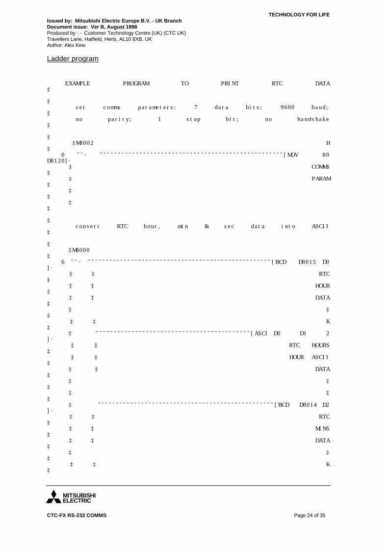
Ladder program
EXAMPLE PROGRAM TO PRINT RTC DATA³
³ set comms parameters: 7 data bits; 9600 baud;³ no parity; 1 stop bit; no handshake³
³ ³M8002 H³ 0 ÃÄ´ ÃÄÄÄÄÄÄÄÄÄÄÄÄÄÄÄÄÄÄÄÄÄÄÄÄÄÄÄÄÄÄÄÄÄÄÄÄÄÄÄÄÄÄÄÄÄÄÄÄÄÄ[MOV 80D8120]´ ³ COMMS³ ³ PARAM³ ³³ ³³
³ convert RTC hour, min & sec data into ASCII³
³ ³M8000³ 6 ÃÄ´ ÃÄÂÄÄÄÄÄÄÄÄÄÄÄÄÄÄÄÄÄÄÄÄÄÄÄÄÄÄÄÄÄÄÄÄÄÄÄÄÄÄÄÄÄÄÄÄÄÄÄÄ[BCD D8015 D0]´ ³ ³ RTC³ ³ ³ HOUR³ ³ ³ DATA³ ³ ³³ ³ ³ K³ ³ ÃÄÄÄÄÄÄÄÄÄÄÄÄÄÄÄÄÄÄÄÄÄÄÄÄÄÄÄÄÄÄÄÄÄÄÄÄÄÄÄÄÄÄ[ASCI D0 D1 2]´ ³ ³ RTC HOURS³ ³ ³ HOUR ASCII³ ³ ³ DATA³ ³ ³³ ³ ³³ ³ ÃÄÄÄÄÄÄÄÄÄÄÄÄÄÄÄÄÄÄÄÄÄÄÄÄÄÄÄÄÄÄÄÄÄÄÄÄÄÄÄÄÄÄÄÄÄÄÄÄ[BCD D8014 D2]´ ³ ³ RTC³ ³ ³ MINS³ ³ ³ DATA³ ³ ³³ ³ ³ K³

TECHNOLOGY FOR LIFEIssued by: Mitsubishi Electric Europe B.V. - UK BranchDocument issue: Ver B, August 1998Produced by : - Customer Technology Centre (UK) (CTC UK)Travellers Lane, Hatfield, Herts, AL10 8XB, UKAuthor: Alex Kew
MITSUBISHIELECTRIC
CTC-FX RS-232 COMMS Page 25 of 35
³ ÃÄÄÄÄÄÄÄÄÄÄÄÄÄÄÄÄÄÄÄÄÄÄÄÄÄÄÄÄÄÄÄÄÄÄÄÄÄÄÄÄÄÄ[ASCI D2 D3 2]´ ³ ³ RTC MINS³ ³ ³ MINS ASCII³ ³ ³ DATA³ ³ ³³ ³ ³³ ³ ÃÄÄÄÄÄÄÄÄÄÄÄÄÄÄÄÄÄÄÄÄÄÄÄÄÄÄÄÄÄÄÄÄÄÄÄÄÄÄÄÄÄÄÄÄÄÄÄÄ[BCD D8013 D4]´ ³ ³ RTC³ ³ ³ SECS³ ³ ³ DATA³ ³ ³³ ³ ³ K³ ³ ÀÄÄÄÄÄÄÄÄÄÄÄÄÄÄÄÄÄÄÄÄÄÄÄÄÄÄÄÄÄÄÄÄÄÄÄÄÄÄÄÄÄÄ[ASCI D4 D5 2]´ ³ RTC SECS³ ³ SECS ASCII³ ³ DATA³ ³³ ³M8000 K K³ 43 ÃÄ´ ÃÄÄÄÄÄÄÄÄÄÄÄÄÄÄÄÄÄÄÄÄÄÄÄÄÄÄÄÄÄÄÄÄÄÄÄÄÄÄ[RS D100 20 D110 0]´ ³³ ³³ ³³ ³³ ³M8013³ 53 ÃÄ´ ÃÄÄÄÄÄÄÄÄÄÄÄÄÄÄÄÄÄÄÄÄÄÄÄÄÄÄÄÄÄÄÄÄÄÄÄÄÄÄÄÄÄÄÄÄÄÄÄÄÄÄÄÄÄÄÄÄ[PLS M0]´ ³SEC³ ³PULSE³ ³³ ³³
message "TIME IS __: __. __[CR][LF]" is sent³ every second³
³
OR ON ANINPUT?

TECHNOLOGY FOR LIFEIssued by: Mitsubishi Electric Europe B.V. - UK BranchDocument issue: Ver B, August 1998Produced by : - Customer Technology Centre (UK) (CTC UK)Travellers Lane, Hatfield, Herts, AL10 8XB, UKAuthor: Alex Kew
MITSUBISHIELECTRIC
CTC-FX RS-232 COMMS Page 26 of 35
³M0 H³ 56 ÃÄ´ ÃÄÂÄÄÄÄÄÄÄÄÄÄÄÄÄÄÄÄÄÄÄÄÄÄÄÄÄÄÄÄÄÄÄÄÄÄÄÄÄÄÄÄÄÄÄÄÄÄÄÄ[MOV 4954 D100]´ ³ ³³ ³ ³³ ³ ³³ ³ ³³ ³ ³ H³ ³ ÃÄÄÄÄÄÄÄÄÄÄÄÄÄÄÄÄÄÄÄÄÄÄÄÄÄÄÄÄÄÄÄÄÄÄÄÄÄÄÄÄÄÄÄÄÄÄÄÄ[MOV 454D D101]´ ³ ³³ ³ ³³ ³ ³³ ³ ³³ ³ ³ H³ ³ ÃÄÄÄÄÄÄÄÄÄÄÄÄÄÄÄÄÄÄÄÄÄÄÄÄÄÄÄÄÄÄÄÄÄÄÄÄÄÄÄÄÄÄÄÄÄÄÄÄ[MOV 4920 D102]´ ³ ³³ ³ ³³ ³ ³³ ³ ³³ ³ ³ H³ ³ ÃÄÄÄÄÄÄÄÄÄÄÄÄÄÄÄÄÄÄÄÄÄÄÄÄÄÄÄÄÄÄÄÄÄÄÄÄÄÄÄÄÄÄÄÄÄÄÄÄ[MOV 2053 D103]´ ³ ³³ ³ ³³ ³ ³³ ³ ³³ ³ ³³ ³ ÃÄÄÄÄÄÄÄÄÄÄÄÄÄÄÄÄÄÄÄÄÄÄÄÄÄÄÄÄÄÄÄÄÄÄÄÄÄÄÄÄÄÄÄÄÄÄÄÄ[MOV D1 D104]´ ³ ³ HOURS³ ³ ³ ASCII³ ³ ³³ ³ ³³ ³ ³ H³ ³ ÃÄÄÄÄÄÄÄÄÄÄÄÄÄÄÄÄÄÄÄÄÄÄÄÄÄÄÄÄÄÄÄÄÄÄÄÄÄÄÄÄÄÄÄÄÄÄÄÄ[MOV 203A D105]´ ³ ³³ ³ ³³ ³ ³³

TECHNOLOGY FOR LIFEIssued by: Mitsubishi Electric Europe B.V. - UK BranchDocument issue: Ver B, August 1998Produced by : - Customer Technology Centre (UK) (CTC UK)Travellers Lane, Hatfield, Herts, AL10 8XB, UKAuthor: Alex Kew
MITSUBISHIELECTRIC
CTC-FX RS-232 COMMS Page 27 of 35
³ ³³ ³ ³³ ³ ÃÄÄÄÄÄÄÄÄÄÄÄÄÄÄÄÄÄÄÄÄÄÄÄÄÄÄÄÄÄÄÄÄÄÄÄÄÄÄÄÄÄÄÄÄÄÄÄÄ[MOV D3 D106]´ ³ ³ MINS³ ³ ³ ASCII³ ³ ³³ ³ ³³ ³ ³ H³ ³ ÃÄÄÄÄÄÄÄÄÄÄÄÄÄÄÄÄÄÄÄÄÄÄÄÄÄÄÄÄÄÄÄÄÄÄÄÄÄÄÄÄÄÄÄÄÄÄÄÄ[MOV 202E D107]´ ³ ³³ ³ ³³ ³ ³³ ³ ³³ ³ ³³ ³ ÃÄÄÄÄÄÄÄÄÄÄÄÄÄÄÄÄÄÄÄÄÄÄÄÄÄÄÄÄÄÄÄÄÄÄÄÄÄÄÄÄÄÄÄÄÄÄÄÄ[MOV D5 D108]´ ³ ³ SECS³ ³ ³ ASCII³ ³ ³³ ³ ³³ ³ ³ H³ ³ ÃÄÄÄÄÄÄÄÄÄÄÄÄÄÄÄÄÄÄÄÄÄÄÄÄÄÄÄÄÄÄÄÄÄÄÄÄÄÄÄÄÄÄÄÄÄÄÄÄ[MOV A0D D109]´ ³ ³³ ³ ³³ ³ ³³ ³ ³³ ³ ³³ ³ ÀÄÄÄÄÄÄÄÄÄÄÄÄÄÄÄÄÄÄÄÄÄÄÄÄÄÄÄÄÄÄÄÄÄÄÄÄÄÄÄÄÄÄÄÄÄÄÄÄÄÄÄÄÄÄ[SETM8122]´ ³³ ³³ ³³ ³³ 109 ÃÄÄÄÄÄÄÄÄÄÄÄÄÄÄÄÄÄÄÄÄÄÄÄÄÄÄÄÄÄÄÄÄÄÄÄÄÄÄÄÄÄÄÄÄÄÄÄÄÄÄÄÄÄÄÄÄÄÄÄÄÄÄÄÄÄÄ[END]´

TECHNOLOGY FOR LIFEIssued by: Mitsubishi Electric Europe B.V. - UK BranchDocument issue: Ver B, August 1998Produced by : - Customer Technology Centre (UK) (CTC UK)Travellers Lane, Hatfield, Herts, AL10 8XB, UKAuthor: Alex Kew
MITSUBISHIELECTRIC
CTC-FX RS-232 COMMS Page 28 of 35
How it works
When a RTC cassette is connected, the time data is automatically written to specificdata registers within the FX CPU. The program example takes only the time data, whichis automatically written to D8015 (hours), D8014 (mins) and D8013 (secs).The data in each of these registers is continually converted to BCD form, and thenconverted to ASCII using the ASCI instruction. Using the second pulse flag, M8013, themessage “TIME IS ‘HH’: ‘MM’. ‘SS’” is displayed on the computer screen every second.
Things to note
• The main aim of this example is to show how to insert RTC data, which is not fixeddata, into a fixed message. It is useful mostly, perhaps, when the FX is connected toa computer or printer to display/print a production log, or error report, so that itcontains the date and time of the error, etc.
• It is necessary to firstly convert each part of the time information to BCD format
because the ASCI instruction converts hexadecimal digits to ASCII characters.Conveniently, each digit in the time information will be in the range 0-9 (there willnever be, for example, a time 03: 2B. 1A). So BCD form, for this example, will be likehexadecimal without the digits A-F. This data can be ‘put through’ the ASCIinstruction quite easily.
• The ASCI instruction puts the ASCII characters in the correct order for sending. As
this example operates in 16-bit data mode, it will be the lower byte of each register inthe tranmsit buffer that is sent first. So to send, for example, the data for 19 mins, weobviously want it to appear at the receiving device (a computer in this case) as “19”mins, and not “91” mins. The ASCI instruction will convert BCD 19 and store it asASCII 9 (upper byte), ASCII 1 (lower byte). So the tenths data is sent first, followedby the units.
• The example uses the special flag M8013 (the one second pulse flag), so that the
message is sent to the computer every second, so that it appears that the computeris being used as a clock display. Instead of M8013, an input or an M coil can be usedto send the data when it is required (especially when a printer is used).

TECHNOLOGY FOR LIFEIssued by: Mitsubishi Electric Europe B.V. - UK BranchDocument issue: Ver B, August 1998Produced by : - Customer Technology Centre (UK) (CTC UK)Travellers Lane, Hatfield, Herts, AL10 8XB, UKAuthor: Alex Kew
MITSUBISHIELECTRIC
CTC-FX RS-232 COMMS Page 29 of 35
5.4 READING BAR CODES
Many applications require the need to scan a bar code - production monitoring,inventory control, etc. A bar code reader is an RS-232 device that scans a bar code andconverts it to an ASCII string. The following example shows how to a bar code can bescanned, and then displayed on a MAC 90 terminal.
System set up
Ladder program
Set up comms parameters³
³ ³M8002 H³ 0 ÃÄ´ ÃÄÄÄÄÄÄÄÄÄÄÄÄÄÄÄÄÄÄÄÄÄÄÄÄÄÄÄÄÄÄÄÄÄÄÄÄÄÄÄÄÄÄÄÄÄÄÄÄÄÄ[MOV 381D8120]´ ³³ ³³ ³³ ³³ Set up 8 bit mode³
³ ³M8000 M8161³ 6 ÃÄ´ ÃÄÄÄÄÄÄÄÄÄÄÄÄÄÄÄÄÄÄÄÄÄÄÄÄÄÄÄÄÄÄÄÄÄÄÄÄÄÄÄÄÄÄÄÄÄÄÄÄÄÄÄÄÄÄÄÄÄÄÄÄÄÄ()ÄÄ´ ³³ ³³ ³³ ³³
NEW FXFX-232ADP
Bar code reader:
data bits: 8parity: none
stop bits: 1baud: 9600
header: usedterminator: used
handshake:none
MAC 90

TECHNOLOGY FOR LIFEIssued by: Mitsubishi Electric Europe B.V. - UK BranchDocument issue: Ver B, August 1998Produced by : - Customer Technology Centre (UK) (CTC UK)Travellers Lane, Hatfield, Herts, AL10 8XB, UKAuthor: Alex Kew
MITSUBISHIELECTRIC
CTC-FX RS-232 COMMS Page 30 of 35
Actual send and receive instruction³
³ ³M8000 K K³ 9 ÃÄ´ ÃÄÄÄÄÄÄÄÄÄÄÄÄÄÄÄÄÄÄÄÄÄÄÄÄÄÄÄÄÄÄÄÄÄÄÄÄÄÄ[RS D100 1 D0 20]´ ³³ ³³ ³³ move data from d0 to d20³
³ ³M8123 K³ 19 ÃÄ´ ÃÄÂÄÄÄÄÄÄÄÄÄÄÄÄÄÄÄÄÄÄÄÄÄÄÄÄÄÄÄÄÄÄÄÄÄÄÄÄÄÄÄÄÄÄ[BMOV D0 D20 20]´ ³ ³³ ³ ³³ ³ ³³ ³ ³³ ³ ³³ ³ ÀÄÄÄÄÄÄÄÄÄÄÄÄÄÄÄÄÄÄÄÄÄÄÄÄÄÄÄÄÄÄÄÄÄÄÄÄÄÄÄÄÄÄÄÄÄÄÄÄÄÄÄÄÄÄ[RSTM8123]´ ³³ ³³ ³³ ³³ reset V register³
³ ³M8002³ 29 ÃÄ´ ÃÄÄÄÄÄÄÄÄÄÄÄÄÄÄÄÄÄÄÄÄÄÄÄÄÄÄÄÄÄÄÄÄÄÄÄÄÄÄÄÄÄÄÄÄÄÄÄÄÄÄÄÄÄÄÄÄ[RST V]´ ³³ ³³ ³³ ³³ For next loop³
³ ³ K³ 33 ÃÄÄÄÄÄÄÄÄÄÄÄÄÄÄÄÄÄÄÄÄÄÄÄÄÄÄÄÄÄÄÄÄÄÄÄÄÄÄÄÄÄÄÄÄÄÄÄÄÄÄÄÄÄÄÄÄÄÄÄÄ[FOR 13]´ ³³ ³³

TECHNOLOGY FOR LIFEIssued by: Mitsubishi Electric Europe B.V. - UK BranchDocument issue: Ver B, August 1998Produced by : - Customer Technology Centre (UK) (CTC UK)Travellers Lane, Hatfield, Herts, AL10 8XB, UKAuthor: Alex Kew
MITSUBISHIELECTRIC
CTC-FX RS-232 COMMS Page 31 of 35
³³ ³³ Strip off upper 12 bits³
³ ³M8000 H V V³ 36 ÃÄ´ ÃÄÂÄÄÄÄÄÄÄÄÄÄÄÄÄÄÄÄÄÄÄÄÄÄÄÄÄÄÄÄÄÄÄÄÄÄÄÄÄÄÄÄÄÄ[WAND F D20 D40]´ ³ ³³ ³ ³³ ³ ³³ ³ ³³ ³ ³³ ³ ÀÄÄÄÄÄÄÄÄÄÄÄÄÄÄÄÄÄÄÄÄÄÄÄÄÄÄÄÄÄÄÄÄÄÄÄÄÄÄÄÄÄÄÄÄÄÄÄÄÄÄÄÄÄÄ[INC V]´ ³³ ³³ ³³ ³³ ³³ 47ÃÄÄÄÄÄÄÄÄÄÄÄÄÄÄÄÄÄÄÄÄÄÄÄÄÄÄÄÄÄÄÄÄÄÄÄÄÄÄÄÄÄÄÄÄÄÄÄÄÄÄÄÄÄÄÄÄÄÄÄÄÄÄÄÄÄÄ[NEXT]´ ³³ ³³ ³³ ³³ Reset V register³
³ ³M8000³ 48 ÃÄ´ ÃÄÄÄÄÄÄÄÄÄÄÄÄÄÄÄÄÄÄÄÄÄÄÄÄÄÄÄÄÄÄÄÄÄÄÄÄÄÄÄÄÄÄÄÄÄÄÄÄÄÄÄÄÄÄÄÄ[RST V]´ ³³ ³³ ³³ ³³ if reading invalid write 0000 to all 13 words³
³ ³M8000 H³ 52 ÃÄ´ ÃÄÂÄÄÄÄÄÄÄÄÄÄÄÄÄÄÄÄÄÄÄÄÄÄÄÄÄÄÄÄÄÄÄÄÄÄÄÄÄÄÄÄÄÄ[CMP 3F D20 M0]´ ³ ³³

TECHNOLOGY FOR LIFEIssued by: Mitsubishi Electric Europe B.V. - UK BranchDocument issue: Ver B, August 1998Produced by : - Customer Technology Centre (UK) (CTC UK)Travellers Lane, Hatfield, Herts, AL10 8XB, UKAuthor: Alex Kew
MITSUBISHIELECTRIC
CTC-FX RS-232 COMMS Page 32 of 35
³ ³³ ³ ³³ ³ ³³ ³ ³M1 H K³ ³ ÀÄ´ ÃÄÄÄÄÄÄÄÄÄÄÄÄÄÄÄÄÄÄÄÄÄÄÄÄÄÄÄÄÄÄÄÄÄÄÄÄÄÄ[FMOV 0 D40 13]´ ³³ ³³ ³³ ³³ ³³ 68 ÃÄÄÄÄÄÄÄÄÄÄÄÄÄÄÄÄÄÄÄÄÄÄÄÄÄÄÄÄÄÄÄÄÄÄÄÄÄÄÄÄÄÄÄÄÄÄÄÄÄÄÄÄÄÄÄÄÄÄÄÄÄÄÄÄÄÄ[END]´ ³³ ³³ ³³ ³³
How it works
When a bar code is scanned, the individual characters are stored in data registers D40to D52. Each data register can be monitored using the MAC 90, and the 13 digit barcode can be displayed on the screen.
To display a data register value on the MAC 90, set up an ANALOGUE NUMERICobject. The complete code can be displayed when each of the 13 data registers (D40-D52) are displayed as analogue numeric objects next to each other in the same block.

TECHNOLOGY FOR LIFEIssued by: Mitsubishi Electric Europe B.V. - UK BranchDocument issue: Ver B, August 1998Produced by : - Customer Technology Centre (UK) (CTC UK)Travellers Lane, Hatfield, Herts, AL10 8XB, UKAuthor: Alex Kew
MITSUBISHIELECTRIC
CTC-FX RS-232 COMMS Page 33 of 35
Appendix 1 - Standard ASCII character set
HEX COLUMNS STANDARD TABLE FOR HEX TO ASCII CONVERSIONROWS 0 1 2 3 4 5 6 7
0 NUL DLE SP 0 @ P ` p
1 SOH DC1 ! 1 A Q a q
2 STX DC2 " 2 B R b r
3 ETX DC3 # 3 C S c s
4 EOT DC4 $ 4 D T d t
5 ENQ NAK % 5 E U e u
6 ACK SYN & 6 F V f v
7 BEL ETB ' 7 G W g w
8 BS CAN ( 8 H X h x
9 HT EM ) 9 I Y i y
A LF SUB * : J Z j z
B VT ESC + ; K [ k {
C FF FS , < L \ l |
D CR GS - = M ] m }
E SO RS . > N ^ n ~
F SI US / ? O _ o DEL
The table above shows how to find the hex code for ASCII characters. The two digithexadecimal code for each character is expressed [column, row]. E.g. the code for theASCII character ‘A’ is 41H.
Note: The cells in the table with a heavy border are the ASCII character set mostrelevant for use with ‘no-protocol’ communication.
Appendix 2 - converting 25 pin to 9 pin connectors
The table below shows the equivalent pins for a 9-pin D-sub connector to that of the 25-pin D-sub connector, for RS-232 communication. This can be used as a guide forcreating cables.
Signal 25 pin 9 pin
FG 1SD 2 3RD 3 2
RTS 4 7CTS 5 8DSR 6 6SG 7 5CD 8 1
DTR 20 4

TECHNOLOGY FOR LIFEIssued by: Mitsubishi Electric Europe B.V. - UK BranchDocument issue: Ver B, August 1998Produced by : - Customer Technology Centre (UK) (CTC UK)Travellers Lane, Hatfield, Herts, AL10 8XB, UKAuthor: Alex Kew
MITSUBISHIELECTRIC
CTC-FX RS-232 COMMS Page 34 of 35
Appendix 3 - Timing Chart For Handshaking Methods
Handshaking methodSelected in D8120
Send Receive
b10: 1b11: 0Hardware 1,Normal mode
SD
ERDR
RD
ERDR
b10: 1b11: 1Hardware 1,Single line mode
SD
RD
ERb12: 1b11: 0Hardware 2,Normal mode
SD
ERDR
RD
ERDR
b12: 1b11: 1Hardware 2,Single line mode
SD
RD
ERER= DTR DR= DSR
Appendix 4 - Further Reading
JY992D69901FX Communications Manual (RS232, RS485)User’s Manual
JY992D66701FX2N-232IF RS-232C Interface BlockUser Manual
JY992D66001FX2N-232-BD Communications BoardUser Guide
Data Data
Data
Data
Data Data
Data
Data
ReceiveSend
Receive
Send
ReceiveSend
Receive
Send

TECHNOLOGY FOR LIFEIssued by: Mitsubishi Electric Europe B.V. - UK BranchDocument issue: Ver B, August 1998Produced by : - Customer Technology Centre (UK) (CTC UK)Travellers Lane, Hatfield, Herts, AL10 8XB, UKAuthor: Alex Kew
Page 35 of 35
NOTES