a hardware-scheduler for fault detection in rtos-based ... · pdf filemonitoring of the plasma...
TRANSCRIPT

A Hardware-Scheduler for Fault Detection in RTOS-Based Embedded Systems
J. Tarrillo, L. Bolzani, F. Vargas
Electrical Engineering Dept., Catholic University – PUCRS Av. Ipiranga 6681, 90619-900, Porto Alegre, Brazil
Abstract— Nowadays, Real-Time Operating Systems (RTOSs) are often adopted in order to simplify the design of safety-critical applications. However, real-time embedded systems are sensitive to transient faults that can affect the system causing scheduling dysfunctions and consequently changing the correct system behavior. In this context, we propose a new hardware-based approach able to detect faults that change the tasks’ execution time and/or the tasks’ execution flow in embedded systems based on RTOS. To demonstrate the effectiveness and benefits of using the proposed approach, we implemented a hardware prototype named Hardware-Scheduler (Hw-S) that provides real-time monitoring of the Plasma Microprocessor's RTOS in order to detect the above mentioned types of faults. The Hw-S has been evaluated in terms of the introduced area overhead and fault detection capability.
Keywords- Hardware-Scheduler, transient fault detection, embedded systems, Real-Time Operating Systems.
I. INTRODUCTION Embedded systems integrate hardware and software in
order to execute a specific application. Today, several safety-critical embedded systems support real-time applications that have to respect stringent timing constrains. In general terms, real-time systems have to provide not only logically correct results, but also temporally correct results [7]. Thus, if the output value computed in execution time is correct, but this value has been obtained too early or too late, the system behavior may be incorrect. This could be catastrophic considering applications like traffic control, medical life support as well as space stations. Considering real-time systems, it is important to highlight that timing, availability, reliability and safety constrains are crucial to guarantee the correct behavior of the system.
Indeed, the high complexity of the applications has made the adoption of Real-Time Operating Systems (RTOS) necessary in order to simplify the design of real-time applications. Embedded systems based on RTOS exploit some important facilities associated to native intrinsic mechanisms to manage tasks, concurrency, memory, time as well as interrupts. Thus, RTOSs serve as an interface between application software and hardware.
However, real-time embedded systems are subject to different parasitic phenomena induced by the environment, e.g. Single Event Upsets (SEUs) [1] [7]. Such transient faults can affect the applications running on the embedded systems as
well as the RTOS under which they are executed. Consequently, they affect both, correctness of the outputs and the task's deadline. According to [10], transient faults affecting RTOSs of safety-critical systems can generate different types of misbehaviors that can be categorized as follows: syndrome for safety-critical systems without an RTOS or syndrome specific to safety-critical systems including an RTOS. In detail, faults affecting the first group can generate the following syndromes: effect-less, application hang, exception, memory access dysfunction, system crash and incorrect output results. The effects associated to the second group of misbehaviors are: real-time problems, where the specified timing constrains are not respected and scheduling dysfunctions, where the task's scheduling is not correct. This syndrome may cause incorrect output results, real-time problems or system crash. Considering real-time applications, it is possible to assume that the time correctness represents can be more important than the correctness of the output results [10].
Up to now, several new solutions have been proposed in order to deal with the reliability problems of real-time embedded systems. In [2] and [3] two different scheduling algorithms have been proposed in order to improve the robustness of real-time embedded systems. In [4] a new strategy based on redundancy has been proposed. Indeed, a software-based approach able to provide fault detection and correction capabilities has been presented in [5]. In general terms, this solution introduces additional application tasks able to check other application tasks in their workspace memory. Finally, a hardware-based approach able to detect control flow faults affecting real-time multi-task systems has been presented in [6].
However, the previously mentioned solutions provide fault tolerance only for the application level and do not consider faults affecting RTOSs that can be propagated from the application task to the application level. According to [7] about 21% of the faults affecting the application tasks produce a significant system failure. Generally, when faults propagate to the application level, tasks tend to miss their deadlines, to produce incorrect results, to loose their context as well as to re-execute within the same period. Moreover, the work presented in [9] demonstrates that about 34% of the faults injected in the main services of RTOSs cause scheduling dysfunctions. Indeed, about 44% of this misbehavior’s class lead to system crashes, about 34% generate logic results problems and the remaining 22% provoke real-time problems. Finally, it is important to note that fault tolerance techniques proposed up to
2009 12th Euromicro Conference on Digital System Design / Architectures, Methods and Tools
978-0-7695-3782-5/09 $25.00 © 2009 IEEE
DOI 10.1109/DSD.2009.224
341

now can represent feasible solutions, but they cannot guarantee that each task respects its deadline.
In this context, we propose a hardware-based solution able to detect faults affecting the application tasks in embedded systems based on RTOS. The proposed approach provides detection of transient faults that affect the sequence and the timing of tasks. We implemented and validated an Infrastructure Intellectual Property (I-IP) named Hardware-Scheduler (Hw-S) able to monitor the tasks’ execution flow. To evaluate the effectiveness of the proposed solution we adopted a case study using the Hw-S mapped in a FPGA Xilinx Spartan 3E. Indeed, we performed fault injection experiments in order to evaluate the fault detection capability and estimated the introduced overheads associated to the Hw-S implemented.
The paper is organized as follows: Section II presents some basic definitions associated to RTOSs. In Section III we introduce the hardware-based approach proposed in this paper. Section IV describes the case study adopted, the environment used to validate the Hw-S and the fault injection setup. In Section V we summarize the experimental results obtained by fault injection campaigns as well as the introduced overheads. Finally in Section VI we draw the conclusions.
II. BACKGROUND An RTOS is an operating system that guarantees a certain
capability within specified time constraints and provides an interface between the application program (software) and the embedded system (hardware). Basically, RTOSs can be classified in two categories: hard-RTOSs and soft-RTOSs. The main difference between the two categories is that a soft- RTOS can tolerate latencies and responds with decreased service quality but the hard-RTOS has to respect its deadlines, because otherwise the tasks fail. RTOSs provide four main types of basic services to the application program:
• Task management: This module includes services associated to task creation, task scheduling as well as task priority assignment.
• Time management: This module includes services associated to systems’ timing constrains such as task delays and time-outs.
• Dynamic memory allocation: This module includes services associated to file creation, deletion, reposition and protection.
• Interprocess communication and synchronization: This module provides services in order to guarantee the integrity of information exchange and the cooperation between tasks.
The application program is structured as a set of processes. Moreover, some operating systems support an additional structure level named task. A task can be defined as a single process or as a set of processes with data dependencies between them. Thus, tasks generally have some sort of temporal constraints on their behavior. The exact nature of these constrains depends on the scheduling model. A deadline is the time at which a process must finish its execution after being initiated earlier. The period of a periodic process or task is the
interval between initiating successive executions. Generally, a process can be in one of the following three states: blocked, ready or executing. Further, the transfer of execution from one process to another one is called context switch.
III. THE PROPOSED APPROACH In this paper we propose a new hardware-based approach
able to provide fault detection in embedded systems running a RTOS. The proposed approach is based on the development of an I-IP named Hardware-Scheduler (Hw-S). Our goal is to detect the set of faults that affect the application tasks and are propagated to the application level causing system failure. Indeed, the main idea behind our approach is to increase the robustness of the embedded systems based on RTOS, providing the detection of transient faults that are not detected by the native structures present in the RTOS. We specially intend to detect faults causing scheduling dysfunctions (Sequence Errors) and real-time problems (Time Errors). The proposed approach is based on the following ideas:
• The scheduler is an element present in every RTOS and implements a scheduling algorithm that defines the exact moment to execute each task.
• The algorithm is deterministic and known previously.
• The tasks to be executed are implemented by programs stored in a specific memory location and consequently it is possible to define which task has to be executed in every instant of time.
• The task's behavior follows a set of time constraints and is defined by external events.
Fig. 1 shows the block diagram of the adopted real-time
embedded system. External events can influence the Hw-S when it has to decide which task will be executed. Indeed, the Hw-S must have access to the address bus in order to identify the task in execution.
In this context, the Hw-S has to know the set of events that can change the task in execution and the memory address that has to be accessed in order to detect an eventual fault during the activation and execution of the task. It is important to point out that the Hw-S represents a passive element in the embedded system, since it does not influence the execution flow of the system, because it is based on a reading signal.
Figure 1. Block diagram of the adopted embedded system.
Fig. 2 shows in detail the block diagram of the proposed Hw-S that is composed of the following functional blocks:
342
• Task Detector: Based on the information stored in the address table, generated during the compilation of the system, this block identifies the task in execution. The Task Detector reads the address accessed by the microprocessor and compares it with the records stored in the address table. Afterwards, the block sends the identified task to the Fault Detector.
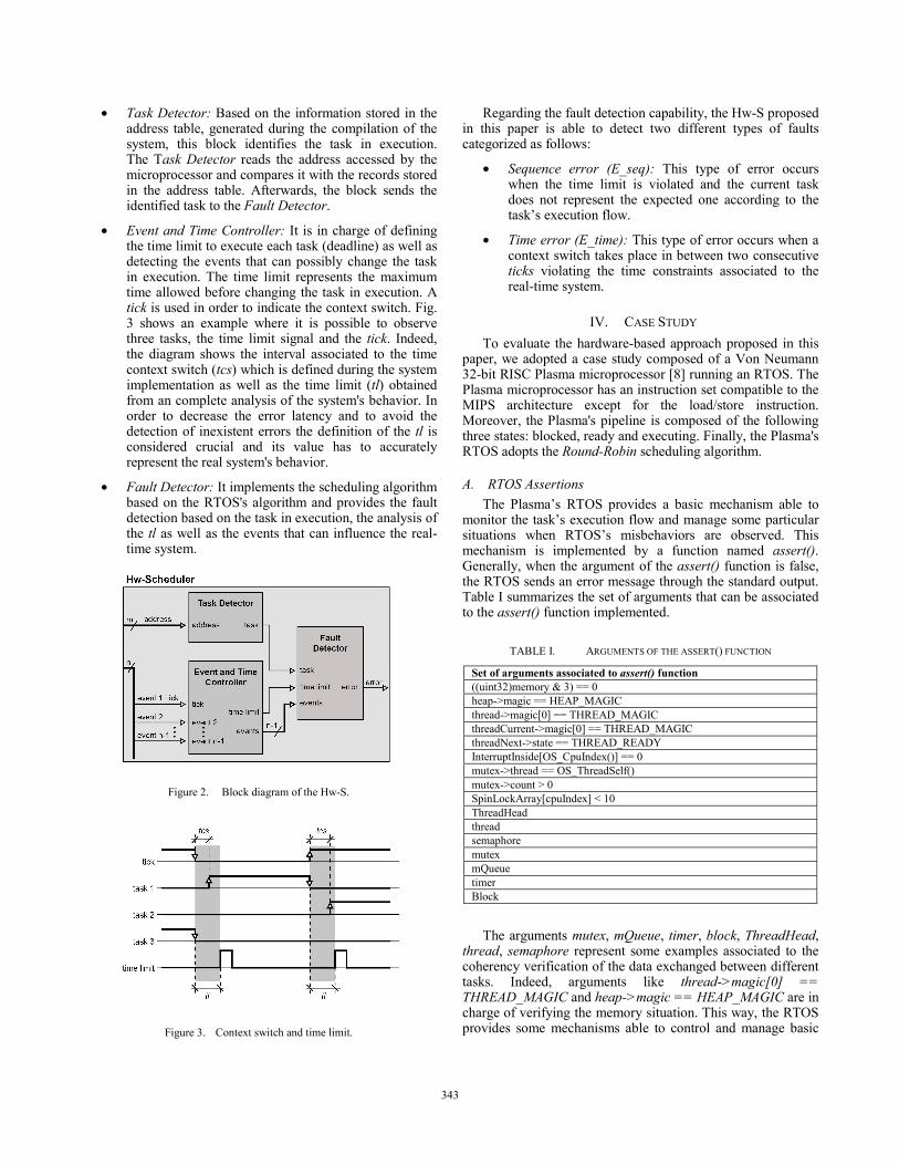
• Event and Time Controller: It is in charge of defining the time limit to execute each task (deadline) as well as detecting the events that can possibly change the task in execution. The time limit represents the maximum time allowed before changing the task in execution. A tick is used in order to indicate the context switch. Fig. 3 shows an example where it is possible to observe three tasks, the time limit signal and the tick. Indeed, the diagram shows the interval associated to the time context switch (tcs) which is defined during the system implementation as well as the time limit (tl) obtained from an complete analysis of the system's behavior. In order to decrease the error latency and to avoid the detection of inexistent errors the definition of the tl is considered crucial and its value has to accurately represent the real system's behavior.
• Fault Detector: It implements the scheduling algorithm based on the RTOS's algorithm and provides the fault detection based on the task in execution, the analysis of the tl as well as the events that can influence the real-time system.
Figure 2. Block diagram of the Hw-S.
Figure 3. Context switch and time limit.
Regarding the fault detection capability, the Hw-S proposed in this paper is able to detect two different types of faults categorized as follows:
• Sequence error (E_seq): This type of error occurs when the time limit is violated and the current task does not represent the expected one according to the task’s execution flow.
• Time error (E_time): This type of error occurs when a context switch takes place in between two consecutive ticks violating the time constraints associated to the real-time system.
IV. CASE STUDY To evaluate the hardware-based approach proposed in this
paper, we adopted a case study composed of a Von Neumann 32-bit RISC Plasma microprocessor [8] running an RTOS. The Plasma microprocessor has an instruction set compatible to the MIPS architecture except for the load/store instruction. Moreover, the Plasma's pipeline is composed of the following three states: blocked, ready and executing. Finally, the Plasma's RTOS adopts the Round-Robin scheduling algorithm.
A. RTOS Assertions The Plasma’s RTOS provides a basic mechanism able to
monitor the task’s execution flow and manage some particular situations when RTOS’s misbehaviors are observed. This mechanism is implemented by a function named assert(). Generally, when the argument of the assert() function is false, the RTOS sends an error message through the standard output. Table I summarizes the set of arguments that can be associated to the assert() function implemented.
TABLE I. ARGUMENTS OF THE ASSERT() FUNCTION
Set of arguments associated to assert() function ((uint32)memory & 3) == 0 heap->magic == HEAP_MAGIC thread->magic[0] == THREAD_MAGIC threadCurrent->magic[0] == THREAD_MAGIC threadNext->state == THREAD_READY InterruptInside[OS_CpuIndex()] == 0 mutex->thread == OS_ThreadSelf() mutex->count > 0 SpinLockArray[cpuIndex] < 10 ThreadHead thread semaphore mutex mQueue timer Block
The arguments mutex, mQueue, timer, block, ThreadHead, thread, semaphore represent some examples associated to the coherency verification of the data exchanged between different tasks. Indeed, arguments like thread->magic[0] == THREAD_MAGIC and heap->magic == HEAP_MAGIC are in charge of verifying the memory situation. This way, the RTOS provides some mechanisms able to control and manage basic
343

situations, where a fault causes misbehaviors of its essential services, such as stack overflow and timing violations.
It is important to highlight that the original Plasma’s RTOS does not provide any mechanism able to detect the faults targeted in this paper (E_seq and E_time). In this scenario, the goal of the proposed approach is to improve the fault detection capability of the Plasma’s RTOS.
B. Hw-S Validation In order to validate the proposed approach, we implemented
a validation environment composed of two main blocks: FPGA Under Test (FPGA UT) and FPGA Supervisor. This environment has been implemented using a FPGA Xilinx Spartan Model XC3S500E. Indeed, we developed one benchmark composed of three tasks, T1, T2 and T3, that access and update the value stored into three different global variables.
Fig. 4 shows the block diagram associated to the architecture implemented to perform the validation of the proposed Hw-S.
Figure 4. Block diagram of the implemented validation environment.
The FPGA UT consists of three sub-blocks that can be defined as follows:
• Plasma microprocessor: It runs the application program (benchmark).
• Hw-S unit: It monitors the tick signal from the Plasma microprocessor as well as the address bus in order to provide fault detection capability. In general terms, when a sequence error or a time error is detected the Hw-S generates the signal E-seq or E-time respectively to indicate the detected error.
• Decoder unit: It decodes the addresses associated to each task in order to monitor the context switch.
The FPGA Supervisor is in charge of monitoring and storing the information generated by the RTOS during execution time and the Hw-S during fault injection campaigns. The Plasma microprocessor presented in this block is implemented in such a way to provide the proper interface between the FPGA UT and the PC. Indeed, the Plasma microprocessor receives the signal to start the test and it downloads the information generated during the fault injection campaigns to the PC. The FPGA Supervisor is composed of the following sub-blocks:
• Control unit: This sub-block enables the other units to save and read the execution flow of the Hw-S as well as the RTOS. In general terms, this unit receives the control signals selection_Hw-S and selection_RTOS from the Plasma microprocessor. Table II shows the behavior of the FPGA Supervisor according to the two input signals. Indeed, the Plasma microprocessor sends the address of the data to be read through the address_in port. Finally, the data read from the memory is sent to the Plasma microprocessor through the data port.
TABLE II. FPGA SUPERVISOR’S BEHAVIOR
Selection HW-S
Selection RTOS Behavior
0 0 Disable test
0 1 Read and send data from RAM Hw-S to the PC
1 0 Read and send data from RAM RTOS to the PC
1 1 Test start: store the execution flow into the RAM Hw-S and RAM RTOS
• RAM Hw-S and RAM RTOS unit: Two 8-bit memories with 1Mbyte of addresses. These memories are used to store the execution flow’s information of the Hw-S and the RTOS.
• Write Memory Hw-S and Write Memory RTOS unit: These units control the read and write memory associated to the RAM Hw-S and the RAM RTOS. Thus, when an error is detected, the Write Memory Hw-S stores the information associated to the type of error and the exact moment, when the error has been detected. The second information is obtained from the
344
Counter Unit. The Write Memory RTOS stores the exactly moment when the context switch is performed into the RAM RTOS. The busy signal indicates that the unit is writing into the respectively associated memory.
• Counter Unit: This unit implements a 28-bits counter that is used to indicate the moment when the data is stored into the memory. It is important to note that the information obtained from the Counter Unit and the clock frequency are used to measure the fault latency between the error's occurrence and its detection by the Hw-S.
C. Fault Injection Setup To evaluate the fault detection capability of the Hw-S, we
developed two benchmarks that exploit some services offered by the Plasma's RTOS. To do so, we implemented three different tasks according to the Round-Robin algorithm. It is important to underline that before performing any fault injection experiment, we carefully studied and tested these applications in an environment without soft-errors in order to guarantee that all tasks meet their deadlines and produce correct output results. The implemented benchmarks are described as follows:
• BM1: Tasks T1, T2 and T3 access and update the value of three different global variables.
• BM2: Tasks T1 and T2 communicate by message queue. T1 sends a value to the queue and T2 reads this value. Task T3 writes a value into a global variable.
The fault injection campaigns have been performed by applying voltage dips to the FPGA UT Vdd pins according to the IEC 61.000-4-29 Normative [11]. The nominal Vdd used is of 1.2V and the periphery (I/O pads) remained at their nominal voltage levels, i.e., 3.3V and 2.5V. These voltage dips were injected in the FPGA pins at a frequency of 0.3MHz. Fig. 5 displays the injected noise captured with the oscilloscope at the Vdd input pins of FPGA UT associated to BM1’s execution. It is important to point out that Power Supply Disturbance (PSD) represents one of the most common sources of transient faults in many embedded applications [12].
Figure 5. IEC 61.000-4-29-compliant injected noise captured with
oscilloscope at the Vdd input pins of FPGA UT.
V. EXPERIMENTAL RESULTS The effectiveness of the proposed hardware-based approach
has been evaluated by fault injection campaigns and by the analysis of the introduced overheads.
During the fault injection campaigns we identified different system behaviors related to the percentage of voltage dips injected in FPGA pins. Thus, we distinguished five different functional states, which go from a fully functional system to a corrupted FPGA configuration. Based on these states we determined the critical voltage range for each benchmarks described above. The behavior of the system has been classified as follows:
• Behavior_1: The system works properly applying this voltage range.
• Behavior_2: Applying this voltage range, transient faults affect the system generating different types of errors that are 100% detected by both RTOS and Hw-S.
• Behavior_3: Applying this voltage range, transient faults generate different types of errors. At the regard, RTOS and Hw-S present different fault detection capability.
• Behavior_4: Applying this voltage range, the microprocessor crashes and needs to be reset.
• Behavior_5: The FPGA’s configuration is corrupted when this voltage range is applied.
The adopted benchmarks use different RTOS services and consequently the microprocessor accesses different parts of the FPGA device, such as, RAM memory or the microprocessor’s internal registers. According to this reasoning, we can observe different levels of sensitivity. In other words, one of the above mentioned behaviors may have a different critical voltage range regarding different benchmarks.
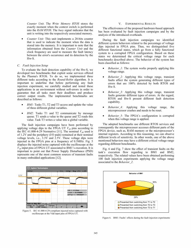
Fig. 6 and Fig. 7 show the effect of transient faults on the task’s execution flow regarding to BM1 and BM2, respectively. The related values have been obtained performing 100 fault injection experiments applying the voltage range associated to the Behavior_2.
Behavior of BM1
35%
29%
36%
Prevented from switching from T1 to T2Prevented from switching from T2 to T3Prevented from switching from T3 to T1
Figure 6. BM1: Faults’ effects during the fault injection experiments
345

According to Fig. 6, we can observe that during 35% of the injected voltage sags, the microprocessor was prevented from moving from T1 to T2. Similar reasoning can be applied to the remaining tasks, during 29% of the voltage dips injected, the microprocessor was prevented from switching from T2 to T3 and during 36% from T3 to T1, respectively.
Behavior of the BM2
11%
28%61%
Prevented from switching from T1 to T2Prevented from switching from T2 to T3Prevented from switching from T3 to T1
Figure 7. BM2: Faults’ effects during the fault injection experiments
Considering Fig. 7, we can observe that during 61% of the voltage dips injected the microprocessor was prevented from moving from T3 to T1, during 28% from T2 to T3 and during 11% from T1 to T2, respectively. These results can be interpreted due to the different RTOS resources that are used during the tasks’ execution. In other words, T1 and T2 exchange data through a queue service, while T3 reads or writes into a global variable stored in the RAM memory. In general terms, T1 makes use of semaphore to control the queue access and this service performs more complex functions than the ones performed during a RAM memory access. Therefore, the system resources associated to T1 are much larger and complex than the ones associated to T3. As conclusion, when the microprocessor tries to switch from T3 to T1, the probability that the large control data required by the microprocessor to run T1 is corrupted is higher when compared to the smaller amount of information to run T3. According to this reasoning, when the microprocessor tries to switch from T3 to T1 and does not find all the required information to restart T1’s execution from the last executed part, the microprocessor remains blocked during T3’s execution. It is important to point out that when this happens, the RTOS sends two different message assertions to the user. The first one is StackOverflow which is generated when the program counter accesses an unexpected memory location. The second message assertion is ThreadHead which is activated when the program counter looses the pointer associated to the next task to be executed.
Moreover, we performed 100 fault injection campaigns for each benchmark applying the voltage dips associated to the Behavior_2, Behavior_3 and Behavior_4 in order to determine the fault detection capability of the Hw-S.
Table III and IV summarize the results obtained during the fault injection experiments with respect to RTOS and Hw-S fault coverage for the BM1 and BM2, respectively.
TABLE III. FAULT COVERAGE ASSOCIATED TO BM1
System behavior
Voltage range [mV]
Voltage Dips [%]
Fault coverage [%] RTOS Hw-S
Behavior_1 [1200-956] 20.34 - - Behavior_2 [955-943] 21.42 100.00 100.0 Behavior_3 [942-858] 28.50 69.00 100.00 Behavior_4 [857-651] 45.75 0.00 100.00 Behavior_5 [650-0] 100.00 - -
TABLE IV. FAULT COVERAGE ASSOCIATED TO BM2
System behavior
Voltage range [mV]
Voltage Dips [%]
Fault coverage [%] RTOS Hw-S
Behavior_1 [1200-1120] 6.67 - - Behavior_2 [1119-893] 25.58 100.00 100.0 Behavior_3 [892-858] 28.50 56.00 100.00 Behavior_4 [857-651] 45.75 0.00 100.00 Behavior_5 [650-0] 100.00 - -
Considering the critical voltage ranges associated to Behavior_2, Behavior_3 and Behavior_4, it is possible to conclude that the Hw-S is able to detect 100% of the transient faults injected during the execution of BM1 and BM2 respectively. However, considering the voltage range associated to Behavior_3, we can observe that the RTOS is not able to detect all injected faults anymore and regarding to Behavior_4 no faults at all. The difference between RTOS and Hw-S fault coverage can be attributed to the fact that the mechanism used by RTOS in order to identify a possible error is more sensitive to voltage sags. Applying voltage sags of 28.50% we observed that during about 40% of the injected faults the Plasma’s RTOS is not able to detect injected faults, because it lost the capacity to send assertions in order to sign an error occurrence. This possibly happens out of two reasons. The first one might be the complete loss of the necessary information to run the Plasma’s RTOS generating inability to detect errors during the tasks’ execution. The second reason could be communication problems associated to the mechanism adopted to send the assertions.
Regarding the detected faults, the sequence errors represent the majority of the errors observed during the fault injection experiments. We identified four different situations with respect to E_seq. The first one happened when the microprocessor did not respect the tasks’ execution flow and jumped to a wrong task. To give an example, the first situation can be observed when the microprocessor jumps directly from T1 to T3. The second situation happened when the microprocessor remained blocked executing only one task without executing the context switch anymore. We attributed it to the fact that the microprocessor lost the information associated to the next task to be executed. The next situation associated to E_seq is observed when the first tick does not provoke a context switch and therefore the same task continuous to be executed till the next tick triggers the context switch and the next task is executed. For example, the tasks’ execution flow could be T1, T1, T2, T3 and so on. When looking at the last situation we can observe that, as in the third one, the first tick does not result in a context switch. But differently, instead of changing to the correct task, the microprocessor executes the context switch and jumps to the
346

next but one task. Thus, the tasks’ execution flow could be T1, T1, T3 and so on.
To conclude, the fault injection campaigns show that the Hw-S reacts significantly more robust when exposed to voltage dips than RTOS only.
Continuing our evaluation, Table V summarizes the area overhead associated to the Hw-S with respect to the Plasma microprocessor.
TABLE V. AREA OVERHEAD
Element Plasma [#]
Hw-S [#]
Overhead [%]
Number of LUTs of 4 inputs 3306 333 10.07
Number of RAM blocks 4 0 0.00
Observing Table V, it is possible to conclude that the overhead introduced by the Hw-S is about 10%. We assume that this number tends to decrease when we consider more complex microprocessor architectures.
To finish the evaluation of the proposed approach, we estimated the fault latency of the proposed Hw-S with respect to internal mechanisms implemented by the Plasma’s RTOS (assert() function). The obtained value shows that the Hw-S latency represents about half the time compared to the latency value associated to the RTOS.
VI. CONCLUSIONS In this paper we proposed a hardware-based approach able
to detect transient faults affecting the task’s execution flow and the task’s execution time. In general terms, the proposed approach targets transient faults affecting the RTOS’s task level. We developed an I-IP named Hw-S and performed fault injection campaigns in order to evaluate the effectiveness of the proposed approach.
The main contribution of this paper consists of providing significantly more robust embedded systems based on RTOS, when voltage dips are injected in the FPGA Vdd pin. The proposed approach provides 100% of fault coverage for the identified critical voltage ranges, introducing only about 10% area overhead. However, the non hardened system was able to provide only 69% and 0% in BM1 or 56% and 0% in BM2, respectively. These numbers are sustained by fault injection campaigns. Further the introduction of an Hw-S reduces the fault latency to about 50% with respect to the RTOS’ latency.
To conclude, we are convinced that the hardware-based approach proposed in this paper represents an interesting solution for hardening real-time embedded systems based on RTOS. Therefore, we plan to conduct future works including additional fault injection experiments. We intend to implement still different benchmarks and to evaluate the fault detection capabilities of the Hw-S, when exposed to irradiated electromagnetic interference, for example.
ACKNOWLEDGMENT The work reported in this paper has been partially funded by CNPq (Science and Technology Foundation, Brazil).
REFERENCES [1] D. Mossé, R. Melhelm, S. Gosh, “A non-preemptive real-time scheduler
with recovery from transient faults and its implementation”, IEEE Transactions on Software Engineering, Vol. 29, N° 8, pp. 752-767, August 2003.
[2] S. Gosh, R. Melhem, D. Mossé, J. Sarma, “Fault-tolerant Rate Monotonic Scheduling”, Journal of Real-time Systems, , vol. 15, N° 2, September 1998.
[3] P. Mejia-Alvarez, D. Mossé, “A responsiveness approach for scheduling fault-recovery in real-time systems”, 5th Real-Time Technology and Applications Symposium, pp. 83-93, 2nd - 4th June 1999.
[4] V. Izosimov, P. Pop, P. Eles, Z. Peng, “Design optimization of time- and cost-constrained fault-tolerant distributed embedded systems”, Desgin, Automation and Test in Europe, Munich, Germany, pp. 864-869, 2005.
[5] Ph. Shirvani, R. Saxena. E.J. McCluskey, “Software-implemented EDAC protection against SEUs”, IEEE Transaction on Reliability, Vol. 49, N° 3, pp. 273-284, September 2000.
[6] F. Vargas, L. Piccoli, A.A. Alecrim, M. Moraes, M. Gama, “Time-Sensitive Control-Flow Checking Monitoring for Multitask SoCs”, IEEE East-West Design & Test Symposium, Sochi, Russia, 2006.
[7] N. Ignat, B. Nicolescu, Y. Savari, G. Nicolescy, “Soft-Error Classification and Impact Analysis on Real-Time Operating Systems”, Design, Automation and Test in Europe 2006.
[8] www.opencores.org [9] M.H Neishaburi, M. Daneshtalab, M. R. Kakoee, S. Safari, “Improving
Robustness of Real-Time Operating Systems (RTOS) Services Related to Soft-Errors, Computer Systems and Applications, AICCSA’07, 2007.
[10] B. Nicolescu, N. Ignat, Y. Savaria, G. Nicolescu, “Analysis of Real-Time Systems Sensitivity to Transient Faults Using MicroC Kernel”, IEEE Transactions on Nuclear Science, Vol. 53, N. 4, August 2006.
[11] IEC International Standards. www.iec.ch. [12] G. Miremadi, J. Torin, “Evaluating Processor-Behavior and Three Error-
Detection Mechanisms Using Physical Fault-Injection”, IEEE Transactions on Reliability, Vol. 44, N. 3, September 1995.
347