a high-efficiency low-cost dc-dc converter for sofc library/research/coal...a high-efficiency...
TRANSCRIPT

A High-Efficiency Low-CostDC-DC Converter for SOFC
February 19-20, 2003
SECA Core Technology Program Review Meeting
Sacramento, California
Presented by Dr. Jason Lai
Virginia Polytechnic Institute and State University

Project Team• Technical Team:
– Virginia Tech Jason Lai: PI Damian Urciouli: Power circuit design, simulation, and implementation Elton Pepa: Magnetic circuit design, soft switching, conditioning circuit design, and testingChris Smith: Control design, digital signal processor (DSP) controller design and implementation
– EPRI Power Electronics Applications CenterTom Key: Test protocol development Tom Geist: Fuel cell setup and testingHaresh Kamath: Fuel cell testing
• Sponsor: – Don Collins, DOE National Energy Technology
Laboratory

Technical Issues
1. Low Voltage – SECA SOFC voltage is as low as 20 V, and silicon band-gap is 0.7 V. Any device junction means 3.5% conduction loss.
2. High Converter Cost – Typical commercial power supply sold $1/W. It is desirable to drop the cost down to 4¢/W or $40/kW for the SECA 5-kW SOFC.
3. Interfacing Converter and Fuel Cell – Power converters draw tremendous current ripple from fuel cell. What are the impacts? Is there a need for a better or more fuel cell friendly power converter?
4. Slow Fuel Cell Dynamic – Power converters experience frequent and fast load transients, but the fuel cell source has a slow dynamic response. What are the impacts? How to deal with energy imbalance between source and load?

A Typical Fuel Cell Power Plant
FuelCell
Source
DC/DCConverter
DC/ACInverter
Loads/Grid
AC LineFilter
• The DC/DC converter is the most crucial electrical interface to the fuel cell source
• Requirements for the DC/DC Converter:High efficiencyHigh reliabilityLow ripple currentCapable of start-up with auxiliary source Capable of communicating with fuel cell Low electromagnetic interference (EMI) emission

Steady-State Fuel Cell Test Results
60 Hz ac load voltage and current
Fuel cell voltage
Fuel cell current
• Significant 120 Hz voltage and current ripple present

Fuel Cell Voltage During Load DumpFrom 1.1 kW to 500 W
46474849505152
-0.04 0 0.04 0.08 0.12 0.16 0.2
Volta
ge (V
)
-15-10-505
1015
-0.04 0 0.04 0.08 0.12 0.16 0.2
Cur
rent
(A)
Time (s)
Inverter output current
Fuel cell output voltage
• Experiment with a 3-kW PEM fuel cell and a 3.3-F ultra capacitor.
• Use incandescent lamps as the load.
• Ultra cap smoothes the load transient effectively.
• Fuel cell time constant is reasonably fast, in millisecond range.

48505254
-0.1 0 0.1 0.2 0.3
Volta
ge (V
)
0102030
-0.1 0 0.1 0.2 0.3
Cur
rent
(A)
-505
1015
-0.1 0 0.1 0.2 0.3
Cur
rent
(A)
-20-10
01020
-0.1 0 0.1 0.2 0.3
Cur
rent
(A)
Time (s)
Inverter output current
Fuel cell voltage
Ultra cap current
Fuel cell current
Fuel Cell Dynamic Response During Single-Phase Motor Start-up Transients
• Ultra cap absorbs significant current during load transient
• Dynamic fuel cell input current and voltage ripples are severe
R&D Objectives
1. Efficiency Improvement2. Cost Reduction 3. Ripple Current Reduction 4. Fuel Cell System Dynamic Response Study

R&D Approaches for Efficiency Improvement
• Selection of circuit topology and control method• Soft switching to eliminate switching losses• Better utilization of power semiconductor devices• Fully utilization of magnetic materials

MOSFET Conduction Loss as a Function of Breakdown Voltage Rating
0.00
0.05
0.10
0.15
0.20
0.25
0 20 40 60 80 100
RDS-on ∝ VBR2.4~2.6
VBR (V)
RD
S-on
(Ω)
Power MOSFET is more cost effective at lower voltagesSelection of circuit topology should take into account the voltage stress of the device.

Efficiency Modeling Approach
• Fuel cell circuit modeling• Transformer modeling• Device modeling• System loss modeling

Fuel Cell Static Modeling
0.4
0.5
0.6
0.7
0.8
0.9
1
1.1
0 0.2 0.4 0.6 0.8 1 1.2 1.4 1.6 1.8
800 ºC
Current (A/cm2)
Volta
ge (V
)
750 ºC
700 ºC
PEMFC
Data source: DOE SECA Modeling team report at Pittsburgh Airport, 10/15/2002

Voltage and Power Characteristics used in System Simulation
15
20
25
30
35
40
45
50
0 50 100 150 200 250 3000
1000
2000
3000
4000
5000
6000
7000
Current (A)
Volta
ge (V
)
Pow
er (V
)
Power
Voltage
(30V, 5kW)
22.5V

Transformer Core Loss EstimationDetermine flux density, Bmax
D: duty cycle Vin: input voltage N1: primary turns Ae: cross section areaf: frequency
fANVDB
e
in
1max
⋅=
fANVVDVBafPe
ine
dccore
1max
⋅= For EE64 planar cored: 3.15 c: 1.6a: 0.053Ve: 40.7 cm3
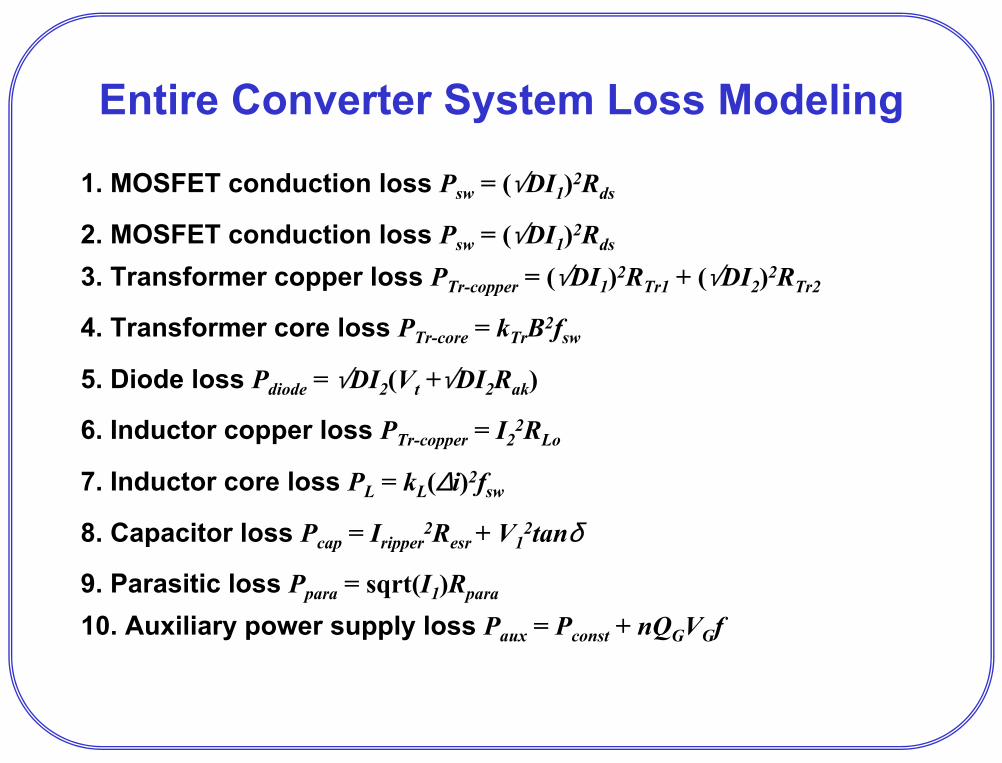
Entire Converter System Loss Modeling
1. MOSFET conduction loss Psw = (√DI1)2Rds
2. MOSFET conduction loss Psw = (√DI1)2Rds
3. Transformer copper loss PTr-copper = (√DI1)2RTr1 + (√DI2)2RTr2
4. Transformer core loss PTr-core = kTrB2fsw
5. Diode loss Pdiode = √DI2(Vt +√DI2Rak)
6. Inductor copper loss PTr-copper = I22RLo
7. Inductor core loss PL = kL(∆i)2fsw
8. Capacitor loss Pcap = Iripper2Resr + V1
2tanδ
9. Parasitic loss Ppara = sqrt(I1)Rpara
10. Auxiliary power supply loss Paux = Pconst + nQGVGf

Efficiency Comparison Among Different Technologies
80%82%84%86%88%90%92%94%96%98%
100%
0 1000 2000 3000 4000 5000 6000
Proposed multiphase converter
1st generation VT full-bridge dc/dc converterEffic
ienc
y
Power (W)
Full-bridge dc/dc converter with beef-up design
Typical commercial power supply
R&D Approaches for Cost Reduction
• Sensorless control technique development• More integration to eliminate interconnects and
associated manufacturing• Design optimization to fully utilize devices and
components• Standardize interface to simplify connections

Major Component Costs in Quantity Production
• For the proposed converter, assuming 4 power MOSFETs in parallel along with six output diodes. At 1,000 quantity, total semiconductor cost = 4 × 6 × $2.4 + 6 × $2.05 = $69.9
• For the planar transformer at 1,000 quantity, transformer cost = $60.• For a quantity of >1 million, semiconductor cost is based on the
amount of silicon and plastic. For example, the TO-220 type package MOSFET and TO-247 diode can be negotiated down to ~30¢ each. The total semiconductor cost becomes $9.00. Similarly transformer cost is based on the amount of copper and iron (~$4/lb). The transformer cost will be less than $20.
• It should be noticed that in large quantity production price drops faster with semiconductor devices than with passive components.
• The complete converter cost of $200/5kW is difficult to meet with small quantity production, but not a problem with large enough quantity.

R&D Approaches for Ripple Reduction
• Adopt a multiphase converter with interleaved control to cancel ripples
IL1 IL2
Itotal = IL1 + IL2

Fuel Cell Current Ripple Comparison for Full-Bridge and the Proposed Converter
500100 400200 300t (µs)
0
300
–100
300
–100
fuel cell current with proposed dc/dc converter
fuel cell current with full-bridge dc/dc converter
∆ipk-pk = 100 A
∆ipk-pk = 400 A

R&D Approach for Fuel Cell System Dynamic Response Study
• First-order SOFC modeling with a finite time constant
• Dynamic system modeling and simulation to understand the impact of load transient and to optimize the design

First Order Dynamic Modeling of SOFCRfc
Voc Load(a) Model without dynamic:
Select Voc = 43 V, Rfc = .07 Ω.+vfc–
Rfc(b) Model with first-order dynamic:
Select Voc = 43 V, Rfc = 0.07 Ω, Cfc = 1.43 F. This assumes time constant = 0.1 second = 6 electrical cycles.
Voc Load+
Cfc vfc–
Case study:Vfc = 29 V, Ifc = (43 – 29)/0.07 = 200 A, Pfc = Vfc × Ifc = 5.8 kWWith 95% dc/dc converter efficiency, dc output = 5.5 kWIf downstream inverter efficiency = 95%, then ac output = 5.2 kW

Simulated Converter Responses under Load Dump Condition with τfc=.1 s
40038030
45028.5
400 V dc bus voltage
inverter output current
5010 4020 300t (ms)
0
fuel cell voltage29.5
400
–150
500100 400200 300t (µs)0
fuel cell output current (HF cap = 200 µF)
low-voltage dc bus voltage
300
0
rising up

Results to Date
• Circuit topology has been selected for design optimization– A patent disclosure regarding multiphase converter control
has been prepared for filing • Complete system has been simulated for
performance evaluation – Efficiency: 97% peak– Ripple: <100 A peak-to-peak
• Power circuit board and transformer have been designed and built

Prototype Multiphase Planar Transformer
Features:• Low leakage inductance (<27 nH)• Low core loss (<20 W) • Low copper loss (<20 W) • Low cost (<$60 in 1000 quantity)
Specifications:
Peak power rating: 10 kW for 1 minute Continuous power rating: 6 kW Total loss at 6 kW: 39 W
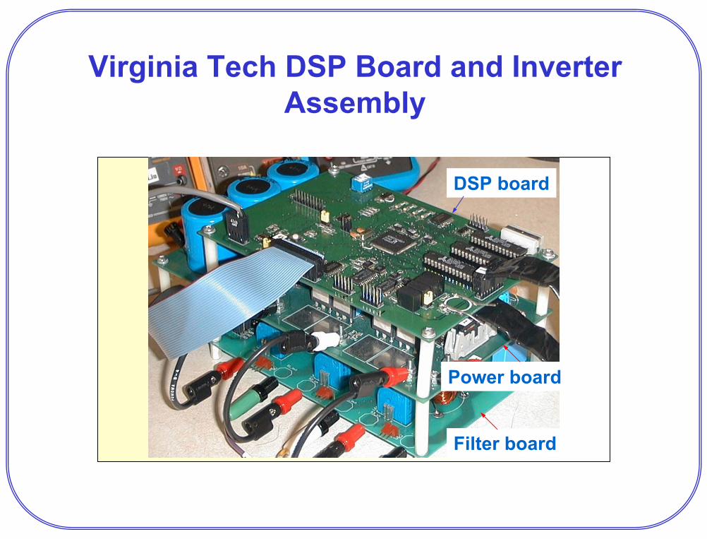
Virginia Tech DSP Board and Inverter Assembly
Power board
DSP board
Filter board
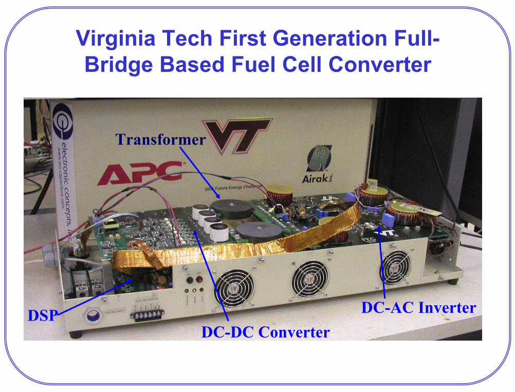
Virginia Tech First Generation Full-Bridge Based Fuel Cell Converter
DC-AC Inverter
Transformer
DSPDC-DC Converter

New Design with Highly Integrated DC/DC Converter Assembly
transformer
Heat sink
Diode/ output
filter board
Converter
power
board
DSP board
Sensor board
Input capacitor
Contactor
9”
22”

Summary of the Proposed Converter
• Fuel cell current ripple reduction: from 400 Apk-to-pkto 100 Apk-to-pk and no negative spike as compared with full-bridge converter
• Output current ripple reduction: reduced passive component losses
• High efficiency: 97% peak efficiency at half load; 96% efficiency at full-load
• Maintain soft switching over a wide load range• DC bus voltage ripple reduction• Sensorless control to reduce cost

Applicability to SOFC Commercialization
• Lower the complete SOFC system cost by increasing power conversion efficiency
• Provide a low-cost and SOFC friendly dc/dc converter
• Path the way for defining power electronics and SOFC interface protocol
• Show dynamic load response and lead to energy balancing strategy between SOFC and output loads
Activities for the Next 6-12 Months
• Complete power circuit testing• Complete sensorless control software coding • Complete converter integration• Test with dc power supply source and ac inverter
load• Work with SECA industrial team members to
evaluate converter performance running under SOFC source
• Define fuel cell and converter interface ( phase II)• Develop interface and communication protocol
( phase II)• Design package for the beta version ( phase II)• Develop energy balancing strategy ( phase II)