a high-fidelity airbus benchmark for system fault ... high-fidelity airbus benchmark for system...
TRANSCRIPT
A HIGH-FIDELITY AIRBUS BENCHMARKFOR SYSTEM FAULT DETECTION
AND ISOLATION AND FLIGHT CONTROLLAW CLEARANCE
Ph. Goupil and G. Puyou
AIRBUS Operations SAS316 Route de Bayonne, Toulouse 31060, France
This paper presents a high-¦delity generic twin engine civil aircraftmodel developed by Airbus for advanced §ight control system research.The main features of this benchmark are described to make the readeraware of the model complexity and representativeness. It is a completerepresentation including the nonlinear rigid-body aircraft model with afull set of control surfaces, actuator models, sensor models, §ight controllaws (FCL), and pilot inputs. Two applications of this benchmark inthe framework of European projects are presented: FCL clearance usingoptimization and advanced fault detection and diagnosis (FDD).
1 INTRODUCTION
Realistic aircraft models are more and more needed for development and as-sessment of new §ight control techniques. Worldwide manufacturers use severalkinds of models and simulators, the complexity of which are adapted to the re-quired level of design and validation. The state of practice is the following: onthe one hand, roughly linear models are used for FCL design and ¦rst assess-ment. On the other hand, system and system components monitoring are widelyused for ensuring the aircraft fault tolerance. They are developed taking intoaccount system speci¦cation and system models and, by a large majority, arebased on hardware redundancy. The whole system validation and veri¦cationproceeds through several steps [1]: tests on a desktop simulator coupled to a rigidaircraft model, tests on a System Integration Bench (a test bench with simulatedinputs and observation of computer internal variables o¨ering the possibility ofvalidating degraded con¦gurations like, e. g., low hydraulic pressure and highaerodynamic loads), tests on the ¤Iron Bird¥ (a bench that is a kind of very
Progress in Flight Dynamics, GNC, and Avionics 6 (2013) 249-262 DOI: 10.1051/eucass/201306249 © Owned by the authors, published by EDP Sciences, 2013
This is an Open Access article distributed under the terms of the Creative Commons Attribution License 2.0, which permits unrestricted use, distribution, and reproduction in any medium, provided the original work is properly cited.
Article available at http://www.eucass-proceedings.eu or http://dx.doi.org/10.1051/eucass/201306249
PROGRESS IN FLIGHT DYNAMICS, GNC, AND AVIONICS
light aircraft, without the fuselage, the structure, the seats, etc., but with allsystem equipment installed and powered as on a real aircraft), and tests on a§ight simulator (a test bench with a real aircraft cockpit, §ight control comput-ers, and coupled to a rigid aircraft model). The §ight simulator can be coupledto the Iron Bird. Finally, §ight tests are performed on several aircraft ¦ttedwith ¤heavy¥ §ight test instrumentation. For transversal studies or for collab-orative works involving the aircraft manufacturer, autonomous means and toolsare needed (decoupled from in-house ones), enough representative but withoutfull access to the manufacturer know-how. This is why simulation benchmarksare developed based on an aircraft model (see, for example, [2] where a Boe-ing model has been used for developing a benchmark dedicated to fault tolerant§ight control scheme design, and additional reference [3]). This paper deals withthe general description of an Airbus benchmark used for advanced Flight Con-trol System development. In particular, the development of such benchmarkwas driven by the requirements of FCL clearance and FDD. It has been usedin the FP6 European COFCLUO (Clearance Of Flight Control Laws Using Op-timization) project [4] and is currently used in the FP7 European ADDSAFEproject (Advanced Fault Diagnosis for Sustainable Flight Control and Guid-ance) [5].The Airbus benchmark is a complete aircraft model, highly representative of
a generic twin engine civil commercial aircraft including the nonlinear rigid-bodyaircraft model with a full set of control surfaces (rudder, elevators, TrimmableHorizontal Stabilizer, spoilers, ailerons), actuator models, sensor models, FCLand pilot inputs. The major issue that drives this model structure is the abilityto perform a validation of requirements on the whole §ight domain consider-ing a wide class of pilot inputs and wind perturbations as well as su©cientlydetailed actuator and sensor models for representative fault injection and diag-nosis.This paper is organized as follows: in section 2, the main features of each
benchmark components will be underlined to show the model complexity andrepresentativeness. Section 3 illustrates the use of the benchmark for FCL clear-ance in the frame of the FP6 European project COFCLUO. Section 4 exem-pli¦es the benchmark as a tool for FDD in the frame of the FP7 Europeanproject ADDSAFE. Some concluding remarks and perspectives are ¦nally givenin section 5.
2 AIRBUS BENCHMARK DESCRIPTION
The model is highly representative of the aircraft §ight physics and handlingqualities. It is a closed-loop nonlinear model based on the following represen-tation (Fig. 1) with ¦ve main components: pilot inputs, FCL, actuators, §ight
250

FAULT DETECTION AND CONTROL
Figure 1 Airbus benchmark structure
mechanics, and sensors. It has been developed under the Matlab/Simulink en-vironment and is usable under the same software thanks to dedicated GraphicalUser Interfaces (GUI). For a given §ight scenario, the aircraft mass and centerof gravity location should be chosen from the mass and balance domain. How-ever, it should be noted that during the course of the chosen scenario, theseparameters do not evolve (e. g., no fuel consumption model).
2.1 Pilot Inputs
The model is controlled through the following inputs: the side stick (longitudinaland lateral inputs), the pedals, the high-lift con¦guration lever (slats and §aps),the airbrakes, and the throttle lever. The side stick, pedal, and thrust inputscan either be de¦ned by the user or independently managed by a pilot modelwhich roughly corresponds to an enhanced set of autopilot hold modes. Eachmode can be independently activated so that users can mix inputs provided bythem and the pilot model.
2.2 Actuator Modeling
The actuator modeling is based on three elements: the actuator model itself, acontrol surface position saturation that could be dissymmetric and a rate limiter
251
PROGRESS IN FLIGHT DYNAMICS, GNC, AND AVIONICS
representing the physical limitations. The model input is the commanded actu-ator position (output of the FCL computation) while the output is the realizedactuator position. Two kinds of models can be used depending on the benchmarkuse. If the goal is to focus on handling qualities evaluation (see section 3), thensimple actuator models are su©cient (¦rst- or second-order transfer functions).If system components fault detection is studied, then a more detailed model canbe used. In this case, the actuator model describes the physical behavior of theactuator rod speed in function of the hydraulic pressure delivered to the actua-tor and in function of the forces applied on the control surface and reacted bythe actuator [6]. It can be expressed by the following deterministic state spacemodel:
‘x(t) = f(u(t), x(t), θ(t)) ;
y(t) = x(t)
where f is the nonlinear function detailed in [6] and θ(t) = [–P (t), Faero(t)Ka(t)]is the vector of parameters representing, respectively, the hydraulic pressuredelivered to the actuator, the aerodynamic forces applying on the control sur-face, and the damping coe©cient associated to the adjacent passive actuator [6](in case of two actuators per control surface in an active/passive scheme). Al-though it is termed an actuator model, it should be noted that the modelingcovers the control loop between the Flight Control Computer and the controlsurface, including these two elements. This benchmark does not aim at study-ing the aircraft management after failure detection or abnormal con¦gurationdetection (automatic failure management so-called ¤recon¦guration¥); so, onlyone actuator is simulated per control surface (no adjacent redundant actua-tor).
2.3 Flight Mechanics
Flight mechanics modeling is based on the so-called fundamental principle ofdynamics. Both quaternion system and Euler angle formulations can be used.The main forces and moments acting on the aircraft are simulated: aerodynamice¨ects, gravity, and engine thrust. When using quaternions, the aircraft motionis described by
m‘�V = Fa + Fg + Fp ;
‘q =12q ⊗ Ÿ ;
IT ‘Ÿ =MaG +MpG − Ÿ ∧ ITŸwhere m is the mass; V is the inertia velocity vector; Fa is the sum of theaerodynamic forces; Fg is the sum of the gravity forces; Fp is the sum of the
252
FAULT DETECTION AND CONTROL
engines forces; q is the quaternion vector describing attitude; Ÿ is the an-gular velocity vector in the aircraft coordinate system; IT is the inertial ten-sor; MaG is the aerodynamic forces induced momentum at the center of grav-ity; and MpG is the engine forces induced momentum at the center of grav-ity.The main forces and moments acting on the aircraft are due to the aerody-
namic e¨ects (Fa andMaG), gravity (Fg), and engine thrust (Fp andMpG). Themain loads used in the §ight mechanics equations are the aerodynamic loads.They are determined most often by identi¦cation of aerodynamic coe©cients(Cb, Cm, Cn, Cx, Cy , and Cz). In this benchmark, these global coe©cients areexpressed through neural network as nonlinear functions of inputs describingthe state of the system such as velocities, altitude, attitude, external conditions,the con¦guration of the aircraft (slats, §aps, spoilers, etc.), and the position ofcontrol surfaces (ailerons, elevators, rudder, etc.). The mass of the aircraft isconsidered to be applied at its center of gravity along the vertical axis. Corre-sponding longitudinal and lateral forces are generated due to the attitude varia-tion. Engine forces are modeled by the forces applied at each engine and directedalong their own longitudinal axes. These axes are projected onto the aircraft co-ordinate system to determine the corresponding components (for more details,see [4]).
2.4 Control Laws
This current benchmark deals with manual control (so autopilot guidance lawsare not included) but for better manoeuvre management, the autothrust controllaw, which is useful for managing the thrust and maintain the speed constant, iskept. Regarding manual laws, as the goal is not to study failure recon¦guration,all the unusual control laws are removed. Except for those points, all inboardcomputer implemented elements are kept. The control law module is a compiledblack-box. The control laws mainly consist of proportional output feedback withan integral control error feedback to ensure zero steady-state tracking error.Their gains are scheduled to cover the whole §ight domain.
2.5 Sensors
An integrated sensor model allows simulating very accurately all sensors involved.A plethora of information is needed and integrated in the model: sensor charac-teristics (location, noise, ¦lter, etc.), calibration data, aerodynamic coe©cients,§ight mechanics equations, system requirements (e. g., delays), etc. This modelis thus very complex and will not be detailed here. A management system hasbeen implemented for simulating the redundant sensor choice and monitoring,
253

PROGRESS IN FLIGHT DYNAMICS, GNC, AND AVIONICS
Figure 2 Use of the benchmark through dedicated GUI
in particular, for FDD studies (see section 4). For more handling qualities ori-ented project, only simple model can be considered like, for instance, ¦rst- orsecond-order transfer functions.Dedicated GUIs facilitate the use of the benchmark (§ight scenario selec-
tion, trimming, etc.) and allow high-level tuning of the fault scenario simulation(Fig. 2).This benchmark has been assessed by comparison with a very high-¦delity
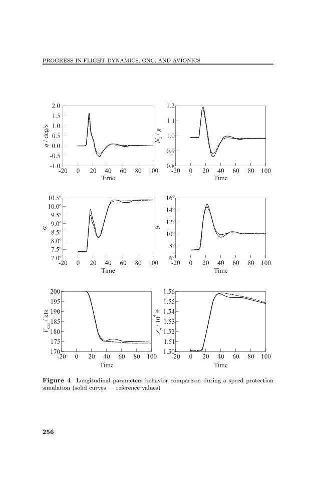
and nonexportable in-house simulator. Open-loop as well as closed-loop valida-tions have been performed to compare control surface positions or aerodynamiccoe©cients without or with solicitations (e. g.,Nz stick input, rudder pedal input,combined lateral/longitudinal solicitations, etc.). Two examples are depictedbelow: ¦rst, a basic longitudinal solicitation is simulated as a double 10 degreeinput on the side-stick (+10◦, then −10◦). The aerodynamic coe©cients (di-mensionless quantity) computed on the open-loop model are displayed in Fig. 3.All coe©cient behaviors (model outputs) are very close to the reference valuesshown with dashed curves. Only CM coe©cient presents a transient divergencearound 30 s but with no signi¦cant consequence on the aircraft behavior. Thesecond example represents a more complex simulation involving a protection lawand speed protection (the aircraft speed must remain inside a predeterminedenvelope for any pilot inputs and wind perturbations). Figure 4 represents thelongitudinal parameters behavior during a manoeuvre triggering the speed pro-tection. The model simulation is very close to the reference behavior.
254

FAULT DETECTION AND CONTROL
Figure 3 Aerodynamic coe©cients comparison on a longitudinal solicitation (solidcurves ¡ reference values)
255
PROGRESS IN FLIGHT DYNAMICS, GNC, AND AVIONICS
Figure 4 Longitudinal parameters behavior comparison during a speed protectionsimulation (solid curves ¡ reference values)
256

FAULT DETECTION AND CONTROL
3 BENCHMARK USE FOR FLIGHT CONTROL LAWCLEARANCE
The previously described benchmark was ¦rst developed for FCL clearancewithin the framework of the COFCLUO European project [4]. The design ofarchitecture of the Airbus FCL is based on the following two-step requirement:
(1) in the usual operating domain, control laws shall provide an instinctive pilot-ing with the same behavior as a conventional aircraft, as well as an accurateand comfortable control, i. e., stability and manoeuvrability, homogeneousaircraft response with respect to pilot inputs in the whole normal §ightenvelope, compensation of aircraft con¦guration changes, minimization ofturbulence e¨ect on the §ight path and the bank angle, balanced e¨ort inpitch and roll, and safe behavior in the case of engine asymmetry detection;and
(2) in extreme situations, FCL shall provide protections in order to remain in thesafe operating domain and reduce the risk of overcontrolling/overstressingthe aircraft while at the same time, giving the highest authority to the pilotin order to achieve best possible aircraft performances, e. g., for avoidancemanoeuvres.
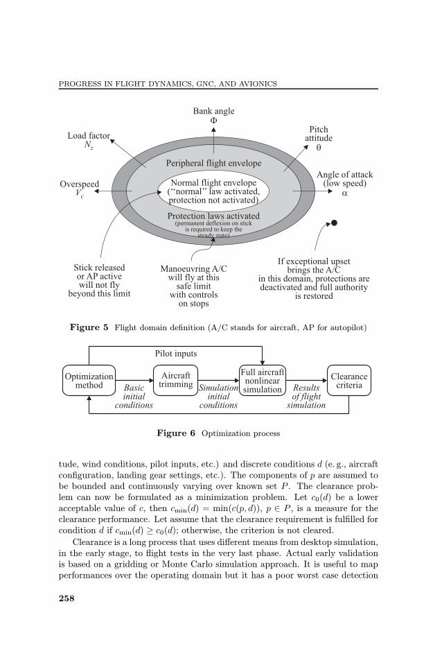
This leads to two §ight envelopes as illustrated in Fig. 5. The normal §ightenvelope inside which the normal laws are activated and the peripheral §ightenvelope inside which a set of protection laws ensures both full authority andsafety to the pilot.Linear tools or extensions (LFT ¡ linear fractional transformation, IQC ¡
integral quadratic constraint) were used to assess performances of FCL in thenormal §ight envelope. Use of the benchmark was focussed on the validationof full-§ight domain protections in the peripheral domain. Since we are dealingwith extreme situations, we are facing high aerodynamic angles, dynamic pilotinputs, and actuator orders. Then, there is a strong need for a high ¦delitybenchmark. It thus requires a good representativeness even in the nonlineardomain. Those nonlinearities a¨ect the §ight mechanics through description ofaerodynamic coe©cients for high angle of attack or sideslip angle. They arealso due to §ight control system itself through use of saturations, dead zone,min/max operators, etc.Once the simulation model is as close as possible to the original aircraft to be
validated, clearance method can be applied. In the frame of the COFCLUOproject, one of the most promising solutions developed is based on use of opti-mization methods coupled with simulations (Fig. 6).For utilizing optimization methods, the clearance problem has to be expressed
as a scalar objective function c(p, d), named criteria, with optimization param-eters p that are uncertain or varying during operation (e. g., inertia, speed, alti-
257
PROGRESS IN FLIGHT DYNAMICS, GNC, AND AVIONICS
Figure 5 Flight domain de¦nition (A/C stands for aircraft, AP for autopilot)
Figure 6 Optimization process
tude, wind conditions, pilot inputs, etc.) and discrete conditions d (e. g., aircraftcon¦guration, landing gear settings, etc.). The components of p are assumed tobe bounded and continuously varying over known set P . The clearance prob-lem can now be formulated as a minimization problem. Let c0(d) be a loweracceptable value of c, then cmin(d) = min(c(p, d)), p ∈ P , is a measure for theclearance performance. Let assume that the clearance requirement is ful¦lled forcondition d if cmin(d) ≥ c0(d); otherwise, the criterion is not cleared.Clearance is a long process that uses di¨erent means from desktop simulation,
in the early stage, to §ight tests in the very last phase. Actual early validationis based on a gridding or Monte Carlo simulation approach. It is useful to mapperformances over the operating domain but it has a poor worst case detection
258

FAULT DETECTION AND CONTROL
rate. It thus can lead to late discovering of problems in the validation phase whenthey occur in a really tiny region. This issue is solved by the use of optimizationas a complement to the previous methods (they are not competing). It shouldlead to early discovery of FCL weaknesses and, thus, save time and money.
4 BENCHMARK USE FOR FAULT DETECTIONAND DIAGNOSIS
A consortium of European industrial partners, research establishments, and uni-versities has been established with funding from the European Union 7th Frame-work Program (EU-FP7) to address the challenge arising from the developmentof the future ¤sustainable¥ aircraft (More A¨ordable, Smarter, Cleaner, andQuieter). The project is termed ADDSAFE [5]. Highlighting the link betweenaircraft sustainability and fault detection, it can be demonstrated that improv-ing the fault diagnosis performance in §ight control systems allows to optimizethe aircraft structural design (resulting in weight saving), which, in turn, helpsimprove aircraft performance and to decrease its environmental footprint (e. g.,fuel consumption and noise). Concretely, if the minimum detectable failure am-plitude can be decreased, the aircraft structural design can be improved andthe aircraft made lighter. So, the overall aim of the project is to research anddevelop model-based FDD methods for aircraft §ight control system fault detec-tion, predominantly sensor and actuator malfunctions.The importance of the studies performed within ADDSAFE arises due to the
industrial representativeness of the benchmark described in this paper, i. e., theaircraft model, and fault problematic. Moreover, the ¦nal goal of the project isto validate the more promising designs in the actual Airbus §ight control systemveri¦cation and validation (V&V) setup: from high-¦delity simulation modelsto the Iron Bird, and including real aircraft actuator rigs ¡ which will ensureindustry-wide acceptance of the results. From a technological and scienti¦c per-spective, the main objectives of the project are:
identi¦cation of a set of guidelines for aircraft guidance and control FDDdesign and analysis;
improved FDD methods and understanding of their applicability to aircraftFDD;
a step towards a V&V process for aircraft advanced diagnostic systems;and
demonstration of the most promising model-based FDD designs on indus-trial state-of-the-art §ight simulation platform.
259

PROGRESS IN FLIGHT DYNAMICS, GNC, AND AVIONICS
Figure 7 ADDSAFE work package structure (LPV ¡ linear parameter varying)
To achieve these objectives, the project is divided in 6 main work packages(from WP0 to WP5) decomposed into a total of 14 technical work packages.Figure 7 illustrates the link between the technical work packages and the projectobjectives fashioned along the lines of the Advisory Council for AeronauticsResearch in Europe (ACARE) strategic research agenda cycle: Basic and SystemResearch Level, Enabling Technologies Level, and Technology Integration Level.The FDD benchmark (WP1.1) to be addressed in ADDSAFE includes the
aircraft model development as well as the fault scenario de¦nition. The whole
260

FAULT DETECTION AND CONTROL
benchmark de¦nition will serve as a design speci¦cation for WP3 (applicationsof FDD designs) and for the industrial assessment in WP4. Three kinds ofscenarios have been de¦ned [5] for covering a wide range of possible sensor andactuator faults related to structural design objectives and aircraft performance,highlighting the impact on the aircraft sustainability.Compared to the benchmark use for FCL clearance, for FDD studies, it has
been modi¦ed for more actuator and sensor model ¦delity and to open up thepossibility to inject representative faults. Actuator modeling covers the con-trol loop and allows simulating fault at a component level like, for example, on§ight control computer input/output which is impossible with a simple transferfunction. Fault propagation through the control loop also allows to reproducenonlinearity and to synthesize a more representative fault. For example, for os-cillatory failure case [6], rather than simulating a pure sinusoid on the controlsurface position, a sinusoid injected at a component level will lead to a morerepresentative oscillation of the control surface, transformed by the nonlinearity.Similarly, more accurate sensor modeling (clinometric, inertial, etc.) allows morerealistic simulation of a wide range of fault types.The benchmark closed-loop simulation environment and representativeness
allow assessment on the whole §ight domain considering a wide class of pilotinputs and perturbations which is crucial for FDD design robustness validation.Moreover, the embedded §ight control laws guarantee an aircraft reaction afterfailure occurrence, and so, a more realistic aircraft behavior. It also representsa step towards industrial assessment before test bench and §ight simulator vali-dation.
5 CONCLUDING REMARKS
Summarizing, this paper is dedicated to a general description of a generic civilaircraft model developed by Airbus for advanced research on §ight control sys-tem. Clearly, the level of modeling can be adapted to the kind of study per-formed. For example, basic actuator models are satisfactory for handling quali-ties oriented works whereas more detailed models are needed for projects dedi-cated to system component FDD. This aircraft model is well adapted to a widerange of §ight control topics.The aerodynamic database model is quite di©cult to obtain. Some improve-
ment could be made as some nonrealistic behaviors have been noticed on someparticular points of the §ight domain. However, this does not compromise thewhole aircraft model representativeness. This aerodynamic modeling will be thetopic of future works as well as a more and more detailed sensor and actuatormodeling for extended FDD studies to system component fault isolation.
261

PROGRESS IN FLIGHT DYNAMICS, GNC, AND AVIONICS
ACKNOWLEDGMENTS
This work was performed in the framework of the European ADDSAFE Project:Grant agreement No.FP7-233815.
REFERENCES
1. Goupil, P. 2011. AIRBUS state of the art and practices on FDI and FTCin §ight control system. Control Eng. Practice 19:524 39. DOI information:10.1016/j.conengprac.2010.12.009.
2. Edwards, C., T. Lombaerts, and H. Smaili, eds. 2010. Fault tolerant §ight con-trol: A benchmark challenge. Lecture notes in control and information sciences ser.Berlin Heidelberg: Springer-Verlag. 399.
3. Marcos, A., and G. J. Balas. 2003. A Boeing 747-100/200 aircraft fault tolerantand fault diagnosis benchmark. Technical Report AEM-UoM-2003-1. Minnesota:University of Minnesota.
4. Varga, A., A. Hansson, and G. Puyou. 2012. Optimization based clearance of §ightcontrol laws: A civil aircraft application. Lecture notes in control and informationsciences ser. Springer-Verlag. 416.
5. Goupil, P., and A. Marcos. 2011. Advanced diagnosis for sustainable §ight guidanceand control: The European ADDSAFE project. SAE 2011 AeroTech Congress andExhibition. Toulouse, France.
6. Goupil, P. 2010. Oscillatory failure case detection in the A380 Electrical FlightControl System by analytical redundancy. Control Eng. Practice 18:1110 19.DOI:10.1016/j.conengprac.2009.04.003.
262