a high pressure x-ray photoelectron spectroscopy ...822432/fulltext01.pdf · a high pressure x-ray...
TRANSCRIPT

A high pressure x-ray photoelectron spectroscopy experimental method forcharacterization of solid-liquid interfaces demonstrated with a Li-ion battery systemJulia Maibach, Chao Xu, Susanna K. Eriksson, John Åhlund, Torbjörn Gustafsson, Hans Siegbahn, HåkanRensmo, Kristina Edström, and Maria Hahlin Citation: Review of Scientific Instruments 86, 044101 (2015); doi: 10.1063/1.4916209 View online: http://dx.doi.org/10.1063/1.4916209 View Table of Contents: http://scitation.aip.org/content/aip/journal/rsi/86/4?ver=pdfcov Published by the AIP Publishing Articles you may be interested in Development of bulk-type all-solid-state lithium-sulfur battery using LiBH4 electrolyte Appl. Phys. Lett. 105, 083901 (2014); 10.1063/1.4893666 Ultrahigh energy density Li-ion batteries based on cathodes of 1D metals with –Li–N–B–N– repeating units inα-Li x BN2 (1 x 3) J. Chem. Phys. 141, 054711 (2014); 10.1063/1.4891868 Novel spectro-electrochemical cell for in situ/operando observation of common composite electrode withliquid electrolyte by X-ray absorption spectroscopy in the tender X-ray region Rev. Sci. Instrum. 85, 084103 (2014); 10.1063/1.4891036 Ab initio study of EMIM- BF 4 crystal interaction with a Li (100) surface as a model for ionic liquid/Li interfacesin Li-ion batteries J. Chem. Phys. 131, 244705 (2009); 10.1063/1.3273087 In situ studies of electrodic materials in Li-ion cells upon cycling performed by very-high-energy x-raydiffraction Appl. Phys. Lett. 79, 27 (2001); 10.1063/1.1383058
This article is copyrighted as indicated in the article. Reuse of AIP content is subject to the terms at: http://scitationnew.aip.org/termsconditions. Downloaded to IP:
130.238.171.99 On: Tue, 16 Jun 2015 14:15:06

REVIEW OF SCIENTIFIC INSTRUMENTS 86, 044101 (2015)
A high pressure x-ray photoelectron spectroscopy experimental methodfor characterization of solid-liquid interfaces demonstrated with a Li-ionbattery system
Julia Maibach,1 Chao Xu,1 Susanna K. Eriksson,2 John Åhlund,3 Torbjörn Gustafsson,1Hans Siegbahn,4 Håkan Rensmo,4 Kristina Edström,1 and Maria Hahlin4,a)1Department of Chemistry–Ångström Laboratory, Uppsala University, Box 538, SE-751 21 Uppsala, Sweden2Department of Chemistry–Ångström Laboratory, Uppsala University, Box 523, SE-751 20 Uppsala, Sweden3VG Scienta AB, Box 15120, SE-750 15 Uppsala, Sweden4Department of Physics and Astronomy, Uppsala University, Box 516, SE-751 20 Uppsala, Sweden
(Received 8 October 2014; accepted 12 March 2015; published online 6 April 2015)
We report a methodology for a direct investigation of the solid/liquid interface using high pressurex-ray photoelectron spectroscopy (HPXPS). The technique was demonstrated with an electrochemicalsystem represented by a Li-ion battery using a silicon electrode and a liquid electrolyte of LiClO4in propylene carbonate (PC) cycled versus metallic lithium. For the first time the presence of aliquid electrolyte was realized using a transfer procedure where the sample was introduced into a2 mbar N2 environment in the analysis chamber without an intermediate ultrahigh vacuum (UHV)step in the load lock. The procedure was characterized in detail concerning lateral drop gradients aswell as stability of measurement conditions over time. The X-ray photoelectron spectroscopy (XPS)measurements demonstrate that the solid substrate and the liquid electrolyte can be observed simulta-neously. The results show that the solid electrolyte interphase (SEI) composition for the wet electrodeis stable within the probing time and generally agrees well with traditional UHV studies. Since themethodology can easily be adjusted to various high pressure photoelectron spectroscopy systems,extending the approach towards operando solid/liquid interface studies using liquid electrolytes seemsnow feasible. C 2015 Author(s). All article content, except where otherwise noted, is licensed undera Creative Commons Attribution 3.0 Unported License. [http://dx.doi.org/10.1063/1.4916209]
INTRODUCTION
In electrochemical systems, the conversion between elec-trical and chemical energy occurs through redox reactions inthe interface region between a solid electrode material andmost often a liquid electrolyte. Improvements of such systemswhen it comes to efficiency, long term stability, etc., requirein-depth knowledge of the composition, formation, and chem-ical processes occurring at these interfaces under operatingconditions.1 For example, in Li-ion batteries the first lithiationprocess is accompanied with an irreversible loss of cycleablelithium due to the formation of an interphase layer at the nega-tive electrode. This functional layer is referred to as the solidelectrolyte interphase (SEI),2–4 and the composition of the SEIlargely influences the short and long-term performance of thebattery. Therefore, understanding the formation, composition,and dynamics of the SEI is a key question in Li-ion batterydevelopment.
A variety of characterization techniques have been appliedto investigate SEI formation, such as atomic force microscopy(AFM), scanning electron microscopy (SEM), transmissionelectron microscopy (TEM), X-ray photoelectron spectros-copy (XPS), and Fourier transform infrared spectroscopy(FTIR).3,5 Among all these techniques, XPS, with its highsurface sensitivity, is a technique perfectly suited to study the
a)E-mail: [email protected]
composition of the interfaces in Li-ion batteries and has assuch already been widely used in this field.6–11 Specifically, thecombination of synchrotron radiation based soft and hard x-rayphotoelectron spectroscopy is capable of yielding comprehen-sive information about the SEI through non-destructive depth-profiling.6,10,12–14
Traditionally, electron spectroscopy has been limited tomeasurements under high to ultrahigh vacuum conditions(UHV) (below 10−6 mbar). The recent instrumental devel-opments, e.g., introducing efficient differential pumping sys-tems, have relaxed the vacuum constraints, and the field ofhigh pressure x-ray photoelectron spectroscopy (HPXPS) hasdeveloped.15 The growth of new instrumentation for HPXPSsystems has been very rapid during the past years both whenit comes to in-house and synchrotron based setups. It startedin Uppsala by Siegbahn and co-workers in the 1970’s wherein-house based systems for gases at high pressures and liquidswere developed.16–19 These laboratory based systems were fol-lowed by installations at synchrotron radiation facilities.19–23
Recently, high performing laboratory based HPXPS systemshave again emerged, and the technique is now commerciallyavailable.15,24,25
When it comes to battery research, the new HPXPS instru-mental developments allow for XPS measurement under morerealistic battery operating conditions. In some of the HPXPSinstruments, measurements at pressures of up to 25 mbar arepossible.15,26,27 Although this does not fully reach atmosphericconditions, this pressure is higher than the vapor pressure of
0034-6748/2015/86(4)/044101/8 86, 044101-1 © Author(s) 2015 This article is copyrighted as indicated in the article. Reuse of AIP content is subject to the terms at: http://scitationnew.aip.org/termsconditions. Downloaded to IP:
130.238.171.99 On: Tue, 16 Jun 2015 14:15:06

044101-2 Maibach et al. Rev. Sci. Instrum. 86, 044101 (2015)
many Li-ion battery electrolyte solvents, and, most impor-tantly, these pressures allow liquid electrolyte to be presentwithin the analysis chamber of a HPXPS instrument. This isa remarkable step forward in instrumentation usability whenit comes to understanding batteries in operando at an elementspecific chemical level.
To date, only a few published articles on in situ HPXPSstudies of Li-ion batteries can be found.28–30 In these, it hasbeen demonstrated that HPXPS can be used for followingthe electrochemical processes in batteries and obtaining newinsights into the reaction mechanism in the Li-air chemistry.Common for the investigated systems is, however, that theydo not contain the interface between the solid electrode andthe electrolyte. In this article, we present a versatile HPXPSmethod for measuring directly at the solid/liquid interface thatcan be swiftly implemented on Li-ion battery systems. Thebattery is not exposed to air and needs no intermediate UHVsample introduction step. This article reports for the first timeHPXPS results on the SEI layer at which also the carbonatebased liquid electrolyte is present.
MATERIALS AND EXPERIMENTAL
The Si|LiClO4 in propylene carbonate (PC)|Li batterysystem was chosen as a model system. The electrolyte solventPC was chosen due to its low vapor pressure of 0.04 mbarat 20 ◦C.31 Silicon was selected as model electrode materialsince it is considered to be the most promising anode mate-rial for next generation lithium ion batteries due to its highgravimetric capacity (∼3600 mAh/g, almost 10 times higherthan conventional graphite electrode).32,33 However, Si anodessuffer from large volume changes during cycling (up to 400%expansion during lithiation), which results in problems such ashigh mechanical stress, active material loss, and loss of electriccontact.34,35 Therefore, an electrochemically and physicallystable SEI is essential for these batteries to achieve long timecycling without rapid capacity fading.
Silicon electrodes were prepared by coating a slurryof silicon nano-powder (Alfa Aesar), super-P carbon black(Erachem Comilog), and sodium carboxymethyl cellulose(CMC-Na, Sigma Aldrich) with a mass ratio of 80:12:8 onto a
copper foil. The slurry was first ball-milled for 1 h and thencasted on the Cu foil using doctor-blading. The electrodes werepunched with a diameter of 20 mm and dried under vacuum at120 ◦C for 12 h. The mass loading of the electrode coating wasapproximately 1.7 mg per punched electrode. The electrolyteused was 1 M LiClO4 (Aldrich) in PC (NOVOLYTE technol-ogies). The salt was dissolved in PC and stirred for 3 days. Thesalt LiClO4 was dried under vacuum at 80 ◦C for 12 h prior tothe electrolyte preparation.
The Silicon|electrolyte|Li half-cell was assembled insidean Argon-filled glove box (O2 < 2 ppm, H2O < 1 ppm) bysandwiching an electrolyte-soaked Solupor polymer separatorbetween the respective Si and Li electrodes and subsequentvacuum-sealing of the stack into a pouch cell. The battery wascycled at a current density of 250 mA/g between 0.01 V and0.9 V (vs. Li/Li+) for 1 cycle. All electrodes were washedand individually vacuum-sealed inside the glove box to betransported to the measurement station without air contact.
The HPXPS setup (see Figure 1) contained a ScientaR4000 HiPP-2 high pressure analyzer and a monochromatizedScienta MX650 HP AlKα X-ray source combined in a systemequipped with an analysis chamber, a load lock chamber,and a manipulator, as reported in Ref. 26. The analyzer wasoperated using the swift acceleration mode type of opera-tion36 using the 0.8 mm diameter front cone. The sample wasplaced 0.8 mm from the first aperture resulting in an actualpressure in the vincinity of the sample of at least 95% of themeasured pressure.20 The sample was introduced via the glovebag (polyethylene glove bag, 91717.LK, VWR InternationalAB) into the load lock in a nitrogen atmosphere (99.999%Alphgaz 1™ from Air Liquide AB). All spectra are internallyreferenced with respect to the C1s emission of carbon black inthe pristine electrode, set to 284.5 eV.37 The spectral intensitiesare normalized to the number of sweeps. Direct comparison ofabsolute intensities is not attempted between different samplesand different measurement positions. However, in cases wheresample position and instrumental settings were kept constant,intensities were compared in order to follow changes withtime. The intensity (peak area) was obtained by integrationof the respective curve fit. The spectra were curve fitted af-ter Shirley background subtraction using Voigt profiles withLorentzian contribution of 20%-30%.
FIG. 1. Schematic representation of the HPXPS setup at VG Scienta, Uppsala. (a) Overview of the pumping and gas inlet system. (b) 3D model in which thepoints of attachment for the glove bag as well as the two N2 inlets are marked by solid arrows. The dashed arrows indicate the approximate sample positions forthe electrolyte drop deposition and the measurement position, respectively.
This article is copyrighted as indicated in the article. Reuse of AIP content is subject to the terms at: http://scitationnew.aip.org/termsconditions. Downloaded to IP:
130.238.171.99 On: Tue, 16 Jun 2015 14:15:06
044101-3 Maibach et al. Rev. Sci. Instrum. 86, 044101 (2015)
METHODOLOGY DEVELOPMENT AND EVALUATION
The development and characterization of a new sampletransfer procedure aiming for HPXPS studies on solid elec-trode electrolyte interfaces is demonstrated. In the sectionson Sample Transfer Procedure, The Electrode ElectrolyteInterface, and Time Dependent Evolution of the ElectrolyteDrop, the use of this transfer procedure for developing a meth-odology for direct measurements on wet functional interfacesis evaluated by comparing measurement positions and byfollowing the solvent evaporation with time. Finally, the firstresults on an electrochemically modified battery interface arediscussed in the section on The Electrode Electrolyte Interfaceon Electrochemically Modified Si Electrode.
Sample transfer procedure
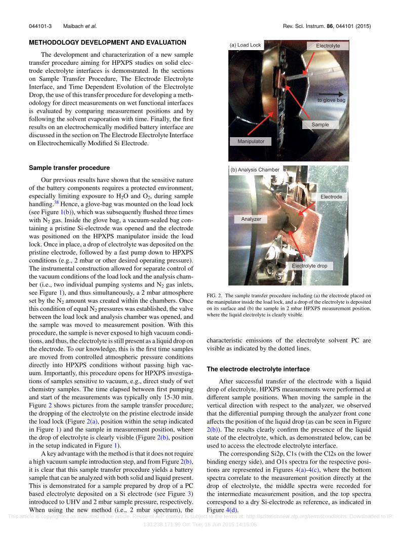
Our previous results have shown that the sensitive natureof the battery components requires a protected environment,especially limiting exposure to H2O and O2, during samplehandling.38 Hence, a glove-bag was mounted on the load lock(see Figure 1(b)), which was subsequently flushed three timeswith N2 gas. Inside the glove bag, a vacuum-sealed bag con-taining a pristine Si-electrode was opened and the electrodewas positioned on the HPXPS manipulator inside the loadlock. Once in place, a drop of electrolyte was deposited on thepristine electrode, followed by a fast pump down to HPXPSconditions (e.g., 2 mbar or other desired operating pressure).The instrumental construction allowed for separate control ofthe vacuum conditions of the load lock and the analysis cham-ber (i.e., two individual pumping systems and N2 gas inlets,see Figure 1), and thus simultaneously, a 2 mbar atmosphereset by the N2 amount was created within the chambers. Oncethis condition of equal N2 pressures was established, the valvebetween the load lock and analysis chamber was opened, andthe sample was moved to measurement position. With thisprocedure, the sample is never exposed to high vacuum condi-tions, and thus, the electrolyte is still present as a liquid drop onthe electrode. To our knowledge, this is the first time samplesare moved from controlled atmospheric pressure conditionsdirectly into HPXPS conditions without passing high vac-uum. Importantly, this procedure opens for HPXPS investiga-tions of samples sensitive to vacuum, e.g., direct study of wetchemistry samples. The time elapsed between first pumpingand start of the measurements was typically only 15-30 min.Figure 2 shows pictures from the sample transfer procedure;the dropping of the electrolyte on the pristine electrode insidethe load lock (Figure 2(a), position within the setup indicatedin Figure 1) and the sample in measurement position, wherethe drop of electrolyte is clearly visible (Figure 2(b), positionin the setup indicated in Figure 1).
A key advantage with the method is that it does not requirea high vacuum sample introduction step, and from Figure 2(b),it is clear that this sample transfer procedure yields a batterysample that can be analyzed with both solid and liquid present.This is demonstrated for a sample prepared by drop of a PCbased electrolyte deposited on a Si electrode (see Figure 3)introduced to UHV and 2 mbar sample pressure, respectively.When using the new method (i.e., 2 mbar spectrum), the
FIG. 2. The sample transfer procedure including (a) the electrode placed onthe manipulator inside the load lock, and a drop of the electrolyte is depositedon its surface and (b) the sample in 2 mbar HPXPS measurement position,where the liquid electrolyte is clearly visible.
characteristic emissions of the electrolyte solvent PC arevisible as indicated by the dotted lines.
The electrode electrolyte interface
After successful transfer of the electrode with a liquiddrop of electrolyte, HPXPS measurements were performed atdifferent sample positions. When moving the sample in thevertical direction with respect to the analyzer, we observedthat the differential pumping through the analyzer front coneaffects the position of the liquid drop (as can be seen in Figure2(b)). The results clearly confirm the presence of the liquidstate of the electrolyte, which, as demonstrated below, can beused to access the electrode electrolyte interface.
The corresponding Si2p, C1s (with the Cl2s on the lowerbinding energy side), and O1s spectra for the respective posi-tions are represented in Figures 4(a)-4(c), where the bottomspectra correlate to the measurement position directly at thedrop of electrolyte, the middle spectra were recorded forthe intermediate measurement position, and the top spectracorrespond to a dry Si-electrode as reference, as indicated inFigure 4(d).
This article is copyrighted as indicated in the article. Reuse of AIP content is subject to the terms at: http://scitationnew.aip.org/termsconditions. Downloaded to IP:
130.238.171.99 On: Tue, 16 Jun 2015 14:15:06

044101-4 Maibach et al. Rev. Sci. Instrum. 86, 044101 (2015)
FIG. 3. Comparison of C1s spectra of a drop of electrolyte on a Si electrodeintroduced to UHV (black) and 2 mbar (red) sample pressure, respectively.The characteristics of the electrolyte solvent PC are indicated by the dottedlines.
From the evolution of Si2p, C1s, and O1s photoemissions,it is clear that the different sample positions give differentrelative core level intensities in a comparison between peaksoriginating from the solid and liquid. In the Si2p region for the
interface measurement position and the reference electrode,all observed emission lines are attributed to the bulk solidelectrode. No distinct Si2p emission could be observed forthe measurement at the regions of the sample with a visuallyobservable electrolyte drop. This indicates that the thicknessof the drop is well beyond three times the inelastic mean freepath of the photoelectrons generated at the solid electrodeelectrolyte interface at the corresponding kinetic energy.39
Consequently, the obtained carbon and oxygen emissions arepredominantly attributed to the electrolyte for this sampleposition. The presence of the electrolyte is also confirmed bythe Cl2s signal at around 280 eV originating from the saltLiClO4 (Cl2p binding energy given in Ref. 40, binding energydifference between Cl2p and Cl2s taken from Ref. 37).
In the C1s spectrum of the liquid electrolyte, the twohigher binding energy peaks are attributed to the carbon atomin the carbonate and ester position in the PC molecule based ontheir characteristic binding energy difference.41 These distinctcontributions from the solvent PC are indicated by the dottedlines in Figure 4. The most intense C1s line most likely origi-nates from the methyl group as well as adsorbed hydrocarbonsindicating that the transfer system relying on a glove bag is notideal in terms of prevention of contaminations. Additionally,it cannot be excluded that carbon containing species fromthe electrode have dissolved in the liquid electrolyte and ac-cumulate at the droplet surface. Contribution from the solidelectrode material in the position referred to as electrolytemay be fully excluded as the photoelectrons at the C1s (andO1s) core level have lower kinetic energy than the electronsstemming from Si2p and the latter is not observed.
To unequivocally access information from the interface,the sample is moved in a vertical direction in front of theanalyzer. For the interface measurement position, a clear Si2psignal is obtained corresponding to the Si2p signal of the
FIG. 4. The core level spectra (Si2p, C1s/Cl2s, and O1s) corresponding to different samples/sample positions are shown in (a)-(c) respectively, in which thereference electrode has blue, the interface red, and electrolyte black color code. Approximate beam positions for the individual measurements are indicated inthe schematic picture (d).
This article is copyrighted as indicated in the article. Reuse of AIP content is subject to the terms at: http://scitationnew.aip.org/termsconditions. Downloaded to IP:
130.238.171.99 On: Tue, 16 Jun 2015 14:15:06

044101-5 Maibach et al. Rev. Sci. Instrum. 86, 044101 (2015)
pristine electrode. In the carbon and oxygen emissions, thepeaks expected for the PC based electrolyte are observed. Ad-ditionally, changes in line-shape compared to the electrolytespectra can be observed also indicating substrate and poten-tially specific interfacial contributions. This becomes evident(i) in the C1s spectra in the changed intensity ratio betweenthe carbonate ester component at 292 eV and the main car-bon emission at 286 eV, which is also broadened due to theoverlap with the substrate carbon black peak and (ii) in theO1s spectra in the intensity increase of the low binding energyoxygen component assigned to bulk electrode (SiOx and CMCbinder) with respect to the shoulder at higher binding energies(i.e., 536 eV). Moreover, the O1s emission in the interfacespectrum can be described as a superposition of electrode andPC signal by taking the reduction in Si2p intensity betweenthe reference electrode and interface spectra as a measure forthe damping of the substrate signal. The presence of bothsubstrate and electrolyte emissions shows that the interfaceregion between solid and liquid is probed.
The presented results clearly demonstrate that with thisapproach, it is possible to obtain information about the func-tional solid-liquid interface between electrode and electrolyteusing HPXPS.
Time dependent evolution of the electrolyte drop
To study the behavior of the liquid electrolyte duringHPXPS measurements in more detail, time dependent studiesat different sample pressures have been performed. The samplepressures were set by the N2 amount. The core level spectrawere recorded for a drop of electrolyte on an electrode at2 mbar as a function of time. These measurements were fol-lowed by measurements at UHV conditions. Similar measure-ments for a drop of electrolyte on an electrode at 0.7 mbarpressure with following pressure reduction to 0.3 mbar andsubsequently to UHV conditions were performed. In Figure 5the time evolution of the O1s and C1s spectra at 2 mbarand subsequently UHV is shown. The zero point of the timescale refers to the starting time of the pumping process (fromN2 atmospheric pressure to the mbar region) during sampleintroduction.
Both the O1s and the C1s emissions undergo a continuouschange in line shape with increasing time between the first andlast measurements at 2 mbar. Once under UHV conditions, thespectral characteristics have changed drastically. Specifically,in the C1s spectrum, the intensity of the two higher bind-ing energy components at 292.2 eV and 288 eV originatingfrom PC decreases with time relative to the C1s component at286 eV. At UHV conditions, the two higher binding energyPC components have vanished. Additionally, the emissionsat 288 eV and 286 eV shift towards lower binding energies.In the O1s spectrum, the line shape gradually changes fromtwo clearly resolved peaks with one at 535.4 eV and a sec-ond at around 533.5 eV to a single, broad peak positionedat 534 eV at UHV conditions. Additionally, an increase inthe Si2p emission from the substrate was detectable from 93min on (see supplementary figure S142). The same qualitativechange in line shapes could be observed for the measurementsat 0.7 mbar with subsequent pressure adjustment to 0.3 mbar
FIG. 5. Evolution of the O1s (a) and C1s (b) core level at 2 mbar andsubsequent UHV exposure as a function of time for a drop of electrolyte on asSi electrode. The original data are represented as dotted lines (red 2 mbar andblack UHV), while the overall fitting results are represented as solid blacklines. The areas used for the following intensity analysis are shaded in red,while the other fitted emissions in the C1s and O1s stemming from PC andthe electrode are shaded gray. The black arrows pointing downwards indicatedecreasing PC components (at 535.4 eV in O1s and 292.2 eV as well as288 eV in C1s). The arrows pointing up in the top UHV spectra indicate theincreasing electrode substrate emissions (at 534 eV in O1s and 285 eV inC1s).
after 80 min and followed by UHV measurements, only thechanges are much more pronounced also for shorter timesin case of lower pressures (see supplementary figure S242).Qualitatively, all these observations are in line with solventevaporation leading to a reduced droplet thickness and thusincreased substrate signal intensity. We therefore conclude thatthe thickness of the liquid electrolyte layer during the proce-dure is within range of the XPS information depth allowing usto probe both the electrolyte as well as the electrode.
In order to further quantify the spectral changes with timeand pressure, the PC contributions in the C1s and O1s spectrawere determined. The overall curve fitting results are repre-sented by solid lines while the original data points are givenas dotted lines in Figure 5. To exemplify the de-convolution,the separate components are shown as shaded areas for thespectra obtained at 11 min and 166 min in Figure 5. The C1scarbonate ester component (shaded red) is not overlappingwith any other component and is thus chosen for primaryevaluation of the electrolyte intensity with time. Due to over-lapping oxygen emissions from substrate and electrolyte, theintensity evaluation of the O1 is more complex; however,in combination with the C1s carbonate ester evaluation, itcan provide information about the solvent. Therefore, alsothe oxygen emission at 535.4 eV originating from the etheroxygen atoms in PC is chosen for evaluation. The obtained
This article is copyrighted as indicated in the article. Reuse of AIP content is subject to the terms at: http://scitationnew.aip.org/termsconditions. Downloaded to IP:
130.238.171.99 On: Tue, 16 Jun 2015 14:15:06

044101-6 Maibach et al. Rev. Sci. Instrum. 86, 044101 (2015)
peak areas from the respective curve fits are plotted as inten-sities relative to the initial intensity (i.e., relative to the firstrecorded spectrum taken at 11 min) versus the time elapsedbetween measurements and first pumping in Figure 6(a). Itis clear that the relative intensity of both the evaluated C1sand O1s components initially decrease rather steadily. Therate of intensity decrease is very similar in carbon and oxygenindicating that the whole PC molecules evaporate.
Plotted in Figure 6(b) is the relative intensity of thecarbonate ester component for the measurements starting at2 mbar and 0.7 mbar, respectively. For a starting pressure of0.7 mbar, the decrease in relative intensity is faster comparedto the measurements starting at 2 mbar, as can be seen fromthe steeper slope described by the individual green squarescompared to the red diamonds in Figure 6(b). These resultsare interpreted as that the N2 base pressure influences the rateof PC evaporation, where a higher base pressure decreases therate of evaporation. As the vapor pressure itself is almost inde-pendent on the ambient pressure in the analysis chamber,43 thiscan be explained by diffusion limitation with increased pres-sure: The diffusion of the evaporating PC molecules throughthe analyzer front cone will be slowed down by the addition ofN2 molecules. This reduces the pumping speed of the solventmolecules and thus increases the time window in which liquidelectrolyte is present.
FIG. 6. Evolution of the relative intensities of the PC photoemission signalsas a function of measurement pressure versus time elapsed after sampleintroduction. (a) C1s (solid red diamond) and O1s (open orange diamond)relative intensity changes for 2 mbar starting pressure. (b) C1s relative inten-sity change for 2 mbar (solid red diamonds), 0.7 mbar (solid green squares)with a subsequent 0.3 mbar (solid blue squares), at UHV conditions afterboth the 2 mbar (solid grey diamonds), and the 0.3 mbar (solid grey squares)measurements. The dotted line indicates the time frame for liquid electrolytemeasurements.
After a pumping step of 30 min going from 2 mbar and0.3 mbar, respectively, to UHV, the relative intensities of thecarbonate ester C1s component is reduced to below 0.1 forboth samples. The sample measured at 2 mbar was kept inUHV for additional 66 h. In the spectra recorded after thistime-period, no emissions from PC could be detected (notshown) indicating complete desorption of PC as also observedwhen going to UHV directly (see Figure 3).
The rate of solvent evaporation appears to slow downto a minimum after a certain measurement time, seen as theflattening and convergence of the data points at around halfthe original intensity for 2 mbar and around 1/3 of the originalintensity for the 0.7 mbar measurements (Figure 6(b)). For the2 mbar measurement, this occurs after around 90 min, whilefor the 0.7 mbar measurement, this occurs after around 70 min.The convergence in evaporation rate is particularly evidentwhen observing the almost unchanged relative C1s intensitywhen decreasing the pressure from 0.7 mbar to 0.3 mbar (bluesquares in Figure 6(b)). Combined, these results indicate achange in the liquid electrolyte structure that affects the rateof evaporation. It can be speculated that this may be linkedto an increased electrolyte salt concentration in the remainingliquid. At the time when the rate flattening is observed, inter-molecular interactions could become stronger and thus reducethe rate of solvent evaporation. For the HPXPS methodologypresented here, this implies that although the time frame ofinvestigating the original electrolyte composition is limited,there is a time frame for measuring a wet surface. Moreover,combining this with the possibility to vary the sample position,it is clear that the important interactions at the solid elec-trode electrolyte interface can be probed. Specifically from thisarticle, it is estimated that using 2 mbar N2 sample pressure forthe 1 M LiClO4 in PC electrolyte yields a measurement timeframe for studying the solid electrode electrolyte interface ofapproximately 90 min.
The electrode electrolyte interfaceon electrochemically modified Si electrode
The developed methodology may be used to study appli-cations where the key function lies in the interactions be-tween a solid sample and a liquid electrolyte. This methodwas therefore used for the investigation of an electrochemi-cally cycled silicon electrode. Prior to the HPXPS measure-ments, the silicon electrode was cycled versus lithium usingan electrolyte consisting of 1 M LiClO4 in PC, thus formingthe SEI on the electrode surface. The electrochemical perfor-mance is provided in Figure S3.42 The goal of these HPXPSmeasurements is to investigate the SEI properties in presenceof the liquid electrolyte. The preliminary characterization wascarried out on fully delithiated silicon electrodes taken directlyfrom cycled batteries. The measurements were performed atdifferent time intervals at 2 mbar N2 pressure and subsequentat UHV (ca. 30 min pumping from 2 mbar to UHV). The XPSresults are shown in Figure 7. The characteristic emissions ofPC showed its evaporation also in this case (C1s peak at 292 eVand O1s peaks at 535.4 eV). As time evolves, the intensities ofthese characteristic solvent peaks decrease and are no longervisible for the subsequent UHV measurement.
This article is copyrighted as indicated in the article. Reuse of AIP content is subject to the terms at: http://scitationnew.aip.org/termsconditions. Downloaded to IP:
130.238.171.99 On: Tue, 16 Jun 2015 14:15:06

044101-7 Maibach et al. Rev. Sci. Instrum. 86, 044101 (2015)
FIG. 7. Evolution of C1s and O1s spectra at 2 mbar (red) and subsequentUHV (grey) for a fully delithiated silicon electrode as a function of time. Theelectrodes were cycled with 1 M LiClO4 in PC electrolyte. The carbon blackspectral contribution is highlighted in black.
The carbon black peak (black in Figure 7) at ca. 283.5 eVbecomes more pronounced as the PC emissions decrease.Since the carbon black only exists in the solid substrateelectrode, the observation of its signal is a clear sign thatthe HPXPS measurement can probe the bulk through thecomplete SEI layer. The relative peak structures originatingfrom the SEI are rather stable with time, and the main differ-ence is primarily due to the evaporation of the solvent. TheSEI layer in this study mainly consists of Li2CO3 (C1s at291.3 eV are O1s at 533 eV), polyether-like compounds, (O1sat 534.2 eV and C1s at 288 eV) and hydrocarbon speciesbeside the LiClO4 salt residue from the electrolyte. Thus, thehere measured SEI composition is similar to that observed inprevious XPS studies on carbonaceous electrodes that havebeen cycled with PC-based liquid electrolytes and where theformed SEI layer is dominated by polyether-, hydrocarbon-,and carbonate-species.3,44 These first HPXPS results show thatthe SEI formed on the Si-anode under present conditions islargely unaffected by the liquid solvent, and that UHV basedstudies on dry samples give a reasonable representation of thecomposition of the SEI in a complete device.
These results imply that the real benefit from HPXPSstudies of battery samples comes when going to operandomeasurements. Many of the components suggested to formwithin the SEI are highly reactive and may react further withthe surrounding components, in this way forming the SEI.3
With operando HPXPS, these initial chemical reactions canbe followed. The open design of the HPXPS introduction andanalysis chamber used in this study,26 allowing insertion ofsamples without exposure to high vacuum, yields the possi-bility to maintain a liquid electrolyte during HPXPS measure-ments. This in turn allows for a simple full battery sampledesign for operando HPXPS measurements by including elec-trical feedthroughs and a counter electrode at the position of
the probed electrode. For operando battery system analysis,improvements to the measurements should include, e.g., bettersample transfer equipment or integration of a glovebox withthe HPXPS instrument to further reduce air exposure.38 Re-placing the N2 gas with Ar would also eliminate the possibilityof Li3N formation in cases where metallic Li is present in thesample.45 Moreover, a more stable electrolyte composition canbe achieved by saturating the atmosphere in the analysis cham-ber with solvent molecules, e.g., by introducing electrolytesolvent at its vapor pressure into the analysis compartment.In realizing this, the chemical processes building up the SEIcan be followed in real time yielding increased understandingof the SEI formation process, ultimately leading to improvedbattery performance.
CONCLUSIONS
For the first time, we present high pressure photoelec-tron spectroscopy results of the solid/liquid interface in Li-ion batteries based on a silicon negative electrode and aPC/LiClO4 electrolyte as a model system. The presence ofliquid electrolyte at the electrode surface was achieved bydesigning a sample preparation and transfer procedure thatallowed the introduction of electrochemical samples into theanalysis chamber without an intermediate UHV step. Theliquid drop was maintained for a sufficiently long period toperform the HPXPS characterizations by introducing a basepressure of N2 in the range of a few millibars, which leads to asignificantly shorter mean free path of the evaporating solventmolecules compared to the mean free path of the emittedphotoelectrons.
By moving the sample in the vertical direction withrespect to the analyzer inlet cone, the region showing the fullsolid/electrolyte interface was pinpointed. It is demonstratedthat for the given system, the solid electrode electrolyte inter-face can be considered stable for time well within the timeframe to conduct thorough HPXPS analysis.
Results obtained from the electrochemically modified Sielectrode with liquid electrolyte showed the presence of an SEIwith a similar composition as observed in measurements atUHV sample pressures. This proves the relevance of previ-ously published UHV XPS studies of the formed SEI andmoreover underlines that the investigated solid electrode elec-trolyte interfaces, obtained via the high pressure sample trans-fer technique described here, are stable.
It is expected that a combination of our transfer techniquewith in situ/operando studies using both hard x-ray photo-electron spectroscopy and high pressure (HP-HAXPES) willyield deeper insights to important intermediate electrochemi-cal processes. Specifically, compositional changes in the liquidelectrolyte, solid electrode, and at their interface could beinvestigated simultaneously.
ACKNOWLEDGMENTS
The research leading to these results has received fundingfrom the European Union’s Seventh Framework Programme(FP7/2007-2013) under Grant Agreement No. 608575. Ad-ditionally, we gratefully acknowledge StandUp for Energy,
This article is copyrighted as indicated in the article. Reuse of AIP content is subject to the terms at: http://scitationnew.aip.org/termsconditions. Downloaded to IP:
130.238.171.99 On: Tue, 16 Jun 2015 14:15:06

044101-8 Maibach et al. Rev. Sci. Instrum. 86, 044101 (2015)
Swedish Energy Agency and the Swedish Research Coun-cil (Grant No. 2012-4681) for financial support. VG Scientaacknowledges funding from Swedish Governmental Agencyfor Innovation Systems (VINNOVA) for the development ofthe Scienta HiPP-2 instrument.
1J. M. Tarascon and M. Armand, “Issues and challenges facing rechargeablelithium batteries,” Nature 414(6861), 359-367 (2001).
2E. Peled, “The electrochemical behavior of alkali and alkaline earth metalsin nonaqueous battery systems—The solid electrolyte interphase model,” J.Electrochem. Soc. 126(12), 2047-2051 (1979).
3K. Xu., “Nonaqueous liquid electrolytes for lithium-based rechargeablebatteries,” Chem. Rev. 104(10), 4303-4418 (2004).
4D. Aurbach et al., “Identification of surface films formed on lithium inpropylene carbonate solutions,” J. Electrochem. Soc. 134(7), 1611-1620(1987).
5P. Verma, P. Maire, and P. Novak, “A review of the features and analysesof the solid electrolyte interphase in Li-ion batteries,” Electrochim. Acta55(22), 6332-6341 (2010).
6K. C. Högström et al., “The influence of PMS-additive on the elec-trode/electrolyte interfaces in LiFePO4/graphite Li-ion batteries,” J. Phys.Chem. C 117(45), 23476-23486 (2013).
7M. Y. Nie et al., “Silicon solid electrolyte interphase (SEI) of lithium ionbattery characterized by microscopy and spectroscopy,” J. Phys. Chem. C117(26), 13403-13412 (2013).
8C. Xu. et al., “Interface layer formation in solid polymer electrolytelithium batteries: An XPS study,” J. Mater. Chem. A 2(20), 7256-7264(2014).
9L. Yang, B. Ravdel, and B. L. Lucht, “Electrolyte reactions with the sur-face of high voltage LiNi0.5Mn1.5O4 cathodes for lithium-ion batteries,”Electrochem. Solid State Lett. 13(8), A95-A97 (2010).
10B. Philippe et al., “Nanosilicon electrodes for lithium-ion batteries: Inter-facial mechanisms studied by hard and soft X-ray photoelectron spectros-copy,” Chem. Mater. 24(6), 1107-1115 (2012).
11V. Etacheri et al., “Effect of fluoroethylene carbonate (FEC) on the perfor-mance and surface chemistry of Si-nanowire Li-ion battery anodes,” Lang-muir 28(1), 965-976 (2012).
12B. Philippe et al., “Role of the LiPF6 salt for the long-term stability of siliconelectrodes in Li-ion batteries–A photoelectron spectroscopy study,” Chem.Mater. 25(3), 394-404 (2013).
13S. Malmgren et al., “Comparing anode and cathode electrode/electrolyteinterface composition and morphology using soft and hard X-ray photoelec-tron spectroscopy,” Electrochim. Acta 97, 23-32 (2013).
14K. C. Högström et al., “Aging of electrode/electrolyte interfaces inLiFePO4/graphite cells cycled with and without PMS additive,” J. Phys.Chem. C 118(24), 12649-12660 (2014).
15D. E. Starr et al., “Investigation of solid/vapor interfaces using ambientpressure X-ray photoelectron spectroscopy,” Chem. Soc. Rev. 42(13), 5833-5857 (2013).
16K. Siegbahn, “From X-Ray to electron-spectroscopy and new trends,” J.Electron Spectrosc. Relat. Phenom. 51, 11-36 (1990).
17M. Faubel, B. Steiner, and J. P. Toennies, “Photoelectron spectroscopy ofliquid water, some alcohols, and pure nonane in free micro jets,” J. Chem.Phys. 106(22), 9013-9031 (1997).
18B. Winter and M. Faubel, “Photoemission from liquid aqueous solutions,”Chem. Rev. 106(4), 1176-1211 (2006).
19M. A. Brown et al., “A new endstation at the Swiss Light Source forultraviolet photoelectron spectroscopy, X-ray photoelectron spectroscopy,and X-ray absorption spectroscopy measurements of liquid solutions,” Rev.Sci. Instrum. 84(7), 073904 (2013).
20D. F. Ogletree et al., “Photoelectron spectroscopy under ambient pressureand temperature conditions,” Nucl. Instrum. Methods Phys. Res., Sect. A601(1–2), 151-160 (2009).
21J. Schnadt et al., “The new ambient-pressure X-ray photoelectron spec-troscopy instrument at MAX-lab,” J. Synchrotron Radiat. 19(5), 701-704(2012).
22M. E. Grass et al., “New ambient pressure photoemission endstation atadvanced light source beamline 9.3.2,” Rev. Sci. Instrum. 81(5), 053106(2010).
23H. Bluhm, “Photoelectron spectroscopy of surfaces under humid condi-tions,” J. Electron Spectrosc. Relat. Phenom. 177(2–3), 71-84 (2010).
24F. Mangolini et al., “Angle-resolved environmental X-ray photoelectronspectroscopy: A new laboratory setup for photoemission studies at pressuresup to 0.4 Torr,” Rev. Sci. Instrum. 83(9), 093112 (2012).
25F. Tao, “Design of an in-house ambient pressure AP-XPS using a bench-topX-ray source and the surface chemistry of ceria under reaction conditions,”Chem. Commun. 48(32), 3812-3814 (2012).
26S. K. Eriksson et al., “A versatile photoelectron spectrometer for pressuresup to 30 mbar,” Rev. Sci. Instrum. 85(7), 075119 (2014).
27S. Kaya et al., “Ambient-pressure photoelectron spectroscopy for heteroge-neous catalysis and electrochemistry,” Catal. Today 205, 101-105 (2013).
28Y.-C. Lu. et al., “In situ ambient pressure X-ray photoelectron spectroscopystudies of lithium-oxygen redox reactions,” Sci. Rep. 2, 715 (2012).
29E. J. Crumlin, H. Bluhm, and Z. Liu, “In situ investigation of electrochemicaldevices using ambient pressure photoelectron spectroscopy,” J. ElectronSpectrosc. Relat. Phenom. 190, 84-92 (2013).
30Y.-C. Lu. et al., “Influence of hydrocarbon and CO2 on the reversibilityof Li–O2 chemistry using in situ ambient pressure X-ray photoelectronspectroscopy,” J. Phys. Chem. C 117(49), 25948-25954 (2013).
31Sigma-Aldrich®, 2014-08-20, Available: http://www.sigmaaldrich.com/catalog/product/sial/310328?lang=en®ion=SE.
32V. Etacheri et al., “Challenges in the development of advanced Li-ion batte-ries: A review,” Energy Environ. Sci. 4(9), 3243-3262 (2011).
33M. N. Obrovac and L. Christensen, “Structural changes in silicon anodesduring lithium insertion/extraction,” Electrochem. Solid State Lett. 7(5),A93-A96 (2004).
34R. Benedek and M. M. Thackeray, “Lithium reactions with intermetallic-compound electrodes,” J. Power Sources 110(2), 406-411 (2002).
35M. J. Chon et al., “Real-time measurement of stress and damage evolu-tion during initial lithiation of crystalline silicon,” Phys. Rev. Lett. 107(4),045503 (2011).
36M. O. M. Edwards et al., “Increased photoelectron transmission in High-pressure photoelectron spectrometers using ‘swift acceleration,”’ Nucl.Instrum. Meth. A 785, 191 (2015).
37J. F. Moulder et al., Handbook of X-Ray Photoelectron Spectroscopy (Phys-ical Electronics, Inc., 1995).
38S. Malmgren et al., “Consequences of air exposure on the lithiated graphiteSEI,” Electrochim. Acta 105, 83-91 (2013).
39S. Hüfner, Photoelectron Spectroscopy: Principles and Applications, 3rd ed.(Springer, Berlin, Heidelberg, New York, 2003).
40D. Martin-Vosshage and B. V. R. Chowdari, “XPS studies on (PEO) nLiClO4 and (PEO) n Cu(ClO4)2 polymer electrolytes,” J. Electrochem. Soc.142(5), 1442-1446 (1995).
41G. Beamson and D. Briggs, High Resolution XPS of Organic Polymers:The Scienta ESCA300 Database (John Wiley & Sons, Ltd., West Sussex,England, 1992).
42See supplementary material at http://dx.doi.org/10.1063/1.4916209 foradditional data on the time dependent evolution of the Si2p peak, theC1s and O1s spectral data of measurements at lower pressures (0.7 and0.3 mbar), and the electrochemical performance data of the Si electrodecycled versus Li metal.
43P. Atkins and J. De Paula, Physical Chemistry, 7th ed. (Oxford UniversityPress, 2002).
44K. Xu. et al., “Chemical analysis of graphite/electrolyte interface formed inLiBOB-based electrolytes,” Electrochem. Solid State Lett. 6(7), A144-A148(2003).
45D. J. David et al., “Surface reactions of lithium with the environment,” Appl.Surf. Sci. 7(3), 185-195 (1981).
This article is copyrighted as indicated in the article. Reuse of AIP content is subject to the terms at: http://scitationnew.aip.org/termsconditions. Downloaded to IP:
130.238.171.99 On: Tue, 16 Jun 2015 14:15:06