a high rate wireless packet data system with versatile qos
TRANSCRIPT

1
WOCC 2004, Taipei
A High Rate Wireless Packet Data System with Versatile QoS
Support
Yucheun JouMarch 8, 2004

2
WOCC 2004, Taipei
QoS Provision in a Wireless Packet System
Inter-user and intra-user quality of service (QoS)• Differentiate data packets with various levels of QoS• Treat data flows differently based on their QoS requirements• Support multiple QoS flows per user
Reverse link (RL) QoS support• RL physical layer hybrid ARQ• Multi-flow fluid media access control (MAC)
Forward link (FL) QoS support • Existing scheme: Provide QoS support with a QoS-sensitive
scheduler• Additional FL QoS Support:
– Small packets and multi-user packets for delay-sensitive applications (gaming, etc.)

3
WOCC 2004, Taipei
RL Physical Layer Hybrid ARQ
Flexible packet length with incremental transmission• Each physical layer packet is transmitted for up to four 4-slot
subpackets– Each slot is 1.67 ms long
• 8-slot interval between successive transmissions of the same packet
• Three 4-slot HARQ interlacesPhysical layer hybrid ARQ• ACK/NAK sent on forward link for every subpacket• Subpackets of a packet are soft-combined −−− incremental
redundancy• Early termination improves throughput as well as delay
performance

4
WOCC 2004, Taipei
RL Hybrid ARQ Operation
1 RL Packet = 16 slots = 26.67 ms Current Reverse Link
Packet 0 Packet 1
1 RL subpacket = 4 slots = 6.67 ms, three interlaces, 12 slots between subpackets of a packet
New Reverse Link
Pkt 0 Pkt 1 Pkt 2 Pkt 3 Pkt 1’ Pkt 4 Pkt 3’ Pkt 1’’
NACK NACK ACK NACK ACK NACK NACK ACK
(FL ARQ Channel)

5
WOCC 2004, Taipei
Enhanced RL Packet Structures (1)
1/5[1.6]
1/5[1.2]
1/5[2.13]
1/4[1]
1/2[1]
1/5[1.07]
1/5[1.6]
1/5[3.2]
1/5[2.4]
1/5[1.6]
1/4[1]
1/5[6.4]
1/5[3.2]
1/5[12.8]
1/5[9.6]
1/5[6.4]
1/5 [3.2]
After 8Slots
After 16Slots
1/5[4.8]
1/5[1.6]
After 12Slots
3/8[1]
38.476.8 51.2
28.857.6 38.4
19.238.4 25.6
9.619.2 12.8
4.89.6 6.4
After 16Slots
After 8Slots
After 12Slots
After 4Slots
After 4Slots
153.6BPSK[5] 1024
115.2BPSK[4] 768
76.8BPSK[3] 512
38.4BPSK[2] 256
19.2BPSK[1] 128
Code Rate [Repetitions]Effective Data Rate (kbps)Modu-lation
PayloadSize(bits)
Note: Current (payload, data rate) configurations are highlighted in blue

6
WOCC 2004, Taipei
Enhanced RL Packet Structures (2)
1/5[1.2]
2/9[1]
1/3[1]
2/3[1]
307.2409.6614.41228.8QPSK
W4 & W2[11]8192
1/3[2]
1/3[1.5]
1/3[1]
2/3[1]
460.8614.4921.61843.28-PSK
W4 & W2[12]1228
8
1/5[1.6]
1/5[1.2]
1/4[1]
1/2[1]
230.4307.2460.4921.6QPSK
W4 & W2[10]6144
1/5[1.6]
1/5[1.2]
1/4[1]
1/2[1]
153.6204.8307.2614.4QPSK
W2[9] 4096
1/5[2.13]
1/5[1.6]
1/5[1.07]
3/8[1]
115.2153.6230.4460.8QPSK
W2[8] 3072
1/5[1.6]
1/5[1.2]
1/5[2.13]
1/5[1.6]
1/4[1]
1/2[1]
1/5[1.07]
3/8[1]
After 8Slots
After 16Slots
After 12Slots
76.8153.6 102.4
57.6115.2 76.8
After 16Slots
After 8Slots
After 12Slots
After 4Slots
After 4 Slots
307.2QPSK
W4[7] 2048
230.4QPSK
W4[6] 1536
Code Rate [Repetitions]Effective Data Rate (kbps)Modu-lation
Payload Size (bits)

7
WOCC 2004, Taipei
QoS Support at RL Physical Layer (1)
Latency improvement• Terminals have the ability to boost transmit power to force
packet termination after the first, second or third subpackettransmission– The power boost procedure is regulated by RL MAC algorithm to
meet latency requirement of delay-sensitive applications (e.g., gaming)
• Ability to start a new packet at any 4-slot boundary– Mean queuing delay is reduced to two slots (compared to eight
slots before)
Flexible tradeoff between capacity and latency• Use longer packets to achieve better coding gain and time
diversity ⇒ higher capacity• Use shorter packets (with power boosting) to reduce
transmission time ⇒ shorter delay

8
WOCC 2004, Taipei
QoS Support at RL Physical Layer (2)
MAC layer ARQ• Enhanced reliability of the last ARQ message for a packet• Detect erased physical layer packet and provide
retransmission directly at the MAC layer• Result in fewer RLP layer retransmissions• Improvement in throughput and delay

9
WOCC 2004, TaipeiRL Sector Throughput Comparison
(57-Sector Embedded Simulation)
DO Rev. 0, No ARQ, 600 Hz PC DO Rev. A, 8-slot termination, 150 Hz PCChan. Num Sect Cap AvgROT Delay Chan. Num Sect Cap AvgROT 4-sl ET DelayModel AT kbps dB ms Model AT kbps dB % ms
A 10 367 5.1 40.0 3 km/h A 10 304 5.2 83.9 13.2B 10 275 5.4 40.0 10 km.h B 10 245 5.3 71.2 15.8C 10 283 5.3 40.0 30 km/h C 10 257 5.2 74.9 15.0D 10 355 5.1 40.0 120 km/h D 10 404 5.1 70.1 16.0E 10 472 5.1 40.0 Rician E 10 600 5.2 51.3 19.7A 4 287 3.5 40.0 3 km/h A 4 408 4.5 83.2 13.4B 4 240 4.1 40.0 10 km.h B 4 310 4.8 68.0 16.4C 4 243 4.1 40.0 30 km/h C 4 331 4.7 71.3 15.7D 4 285 3.6 40.0 120 km/h D 4 462 4.6 60.0 18.0E 4 357 3.5 40.0 Rician E 4 773 4.8 31.4 23.7
DO Rev. A, 16-slot Termination, 150 Hz PCChan. Num Sect Cap AvgROT 4-sl ET 8-sl ET 12-sl ET DelayModel AT kbps dB % % % ms
3 km/h A 10 667 5.2 15.0 62.8 88.9 36.7 10 km.h B 10 521 5.3 9.6 50.4 87.7 40.5 30 km/h C 10 543 5.2 13.6 60.0 90.5 37.2 120 km/h D 10 691 5.1 4.0 46.2 88.6 42.2 Rician E 10 912 5.3 0.9 18.7 78.5 50.4 3 km/h A 4 776 4.6 10.2 57.56 87.66 38.9 10 km.h B 4 661 4.8 5.79 44.07 85.87 42.9 30 km/h C 4 687 4.7 8.44 54.66 89.26 39.5 120 km/h D 4 816 4.6 1.41 36.91 85.81 45.2 Rician E 4 1001 4.9 0.11 12.07 75.07 52.6

10
WOCC 2004, Taipei
RL MAC EnhancementEase of design for QoS• Rapid control of relative throughput and delay among application
flows• Unified approach to inter-user and intra-user QoS• Differentiation of flows within an access terminal (AT) is treated in
the same way as flows from different ATsImproved performance for bursty and fixed-rate sources• Reduced delay and delay variance• Rapid and efficient resource usage
Improved closed-loop control of system loading• More predictable ROT dynamics
Enhanced access channel reduces call setup time• Shorter and more flexible preamble length• Allow access channel data rates up to 38.4 kbps
Flexible rate allocation at each AT via autonomous as well as scheduled modeCompatible with existing physical layer

11
WOCC 2004, TaipeiExample of Unified Approach to
Inter-user and Intra-user QoS
0 1000 2000 3000 4000 5000 6000 7000 8000 9000 10000
101
102
s lot
Thro
ughp
ut (k
bps)
6 AT, 1 Flow/AT, 128-Slot Average Throughput vs . s lot number
0 1000 2000 3000 4000 5000 6000 7000 8000 9000 10000
101
102
s lot
Thro
ughp
ut (k
bps)
2 AT, 3 Flows/AT, 128-Slot Average Throughput vs . s lot number
Inter-user QoS
6 AT’s: 1 Flow/AT
Flow Priority = {4,4,2,2,1,1}
Intra-user QoS:
2 AT’s: 3 Flows/AT
Flow Priority = {4,2,1} {4,2,1}

12
WOCC 2004, Taipei
RLMAC Operation
NotBusy
9.6kbps
19.2kbps
153.6kbps
P1
38.4kbps
76.8kbps
P2 P3 P4
Busy 9.6kbps
19.2kbps
153.6kbps
q1
38.4kbps
76.8kbps
q2 q3 q4
Data
T2P
Subframe T2PAllocation TxT2P
βmax
β
T2P
• Enhanced RL MAC• If QRAB = 1 (busy), reduce AT's
continuous state variable T2P by gd(.)• If QRAB = 0 (not busy), increase T2P
by gu(.)• The actual transmit rate is chosen for
each packet such that the average matches the state variable T2P
• Current RL Mac• Probabilistic rate determination at
the AT based on Reverse Activity Bit (RAB)

13
WOCC 2004, Taipei
QoS Design in RL MACT2P relative priority• Flows can be allocated relative priority, specified by the relative
priority weighting Ci– Ci indicates the flow’s relative sector resource usage, in relation to other
relative priority flows– Ci = 2Cj implies that flow i should get twice the throughput of flow j when
they have the same active set– Ramp functions gu(.) and gd(.) for flow i are determined based on Ci
T2P fixed allocation• Flows can be allocated a fixed T2P, specified as T2Pfix• The flow very quickly achieves a T2Pfix allocation, but may be
restricted from going beyond itSource burstiness design• Flows with bursty sources may transmit a high-rate burst after
being idle for sometime • Flows are designed with a burstiness constraint, specified as βfact(T2P)
• βfact(T2P) indicates the max factor above the current T2P allocation which can ever be used in one allocation
• Allows efficient handling of bursty sources while under average T2P allocation

14
WOCC 2004, TaipeiT2P Allocation Example:One Flow at Fixed T2P = 16
Two at Relative Priority C = 0.5, 1.0
0 1000 2000 3000 4000 5000 6000 7000 8000 9000 100000
10
20
30
40
T2P
s lot
T2P vs . s lot number, ROT Thres h=1.8dB
T2P 1T2P 2T2P 3
0 1000 2000 3000 4000 5000 6000 7000 8000 9000 100000
50
100
150
128-s lot Average Throughput vs . s lot number
AT
AvT
P (k
bps)
s lot
Rate1Rate2Rate3

15
WOCC 2004, TaipeiReverse Link Application Performance
EvaluationSimulations run under 3GPP2 Evaluation Methodology• 19-cell, 57-sector layout with wraparound• Mix of 5 channel models with various fading velocities and
multipath• Link budget scaled to cdma2000© overlay for application simulation
Data source models• VoIP
– TIA/EIA IS-871 Markov Service Option (MSO) for cdma2000 Spread Spectrum Systems model used for voice
† Average rate 3.2 kbps† Multiplex Option 0x01 used (8kbps), no blanking, minimum rate of 1/8
– 4-frame bundling (80 msec)† Design for max delay 160 msec (80 msec bundling + 80 msec transmission)† 16-slot termination goal
• Gaming– 9.6 kbps fixed rate
† Fixed packet size arriving every 40 msec• Video
– Simple video source which models 10 fps QCIF video source† 43 kbps of video, fixed packet size arriving every 100 msec† Same audio as in VoIP case, IS-871 MSO

16
WOCC 2004, TaipeiPerformance Evaluation
57-Sector Layout
17
WOCC 2004, Taipei
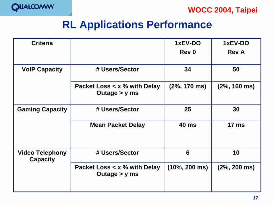
RL Applications Performance
5034# Users/SectorVoIP Capacity
(2%, 160 ms)(2%, 170 ms)Packet Loss < x % with Delay Outage > y ms
3025# Users/SectorGaming Capacity
17 ms40 msMean Packet Delay
106# Users/SectorVideo Telephony Capacity
(2%, 200 ms)(10%, 200 ms)Packet Loss < x % with Delay Outage > y ms
1xEV-DORev A
1xEV-DORev 0
Criteria

18
WOCC 2004, TaipeiRL VoIP Capacity, AT Packet Loss Statistic
57-Sector, 50 AT/Sector, Rev. A, DO Link Budget
0 0.5 1 1.5 2 2.5 3 3.5 4 4.5 5
10-3
10-2
10-1
100
P kt Los s (%) combining P ER and Delay Outage > 150,160ms ec
Pro
porti
on o
f ATs
with
loss
gre
ater
than
Pkt
Los
s
CellHoneyComb19, 50AT, 40000 s lots , DV Mix, MS O Voice Mplex-1
150 ms ec Outage160 ms ec Outage170 ms ec Outage

19
WOCC 2004, Taipei
Forward Link QoS EnhancementsEnhanced QoS support via small packets• Addition of new small payload sizes: 128 bits, 256 bits, 512 bits• Enables FL scheduler to better serve delay-sensitive data to users
in adverse channel conditions• Small packets for control channel improves paging performance
Packet division multiplexing• Multiplexing small upper-layer packets from one or more users into
a single physical-layer packet• Enables FL scheduler to serve data from different QoS flows to one
or more users simultaneously• Improved link utilization while serving delay sensitive applications
Data Source Control (DSC) Channel introduced (on RL) to indicate the desired forward-link serving cell • Minimize service interruption due to server switching on FL• Improved user experience for applications such as wireless gaming
and video telephony

20
WOCC 2004, Taipei
Concluding Remarks
An wireless packet data system providing advanced QoS support is describedCommercial systems are being built based on this designcdma2000 1xEV-DO (1x Evolution – Data Optimized) = TIA-856 standard• Revision A contains all the enhancements described herein