a historical review of high speed metal forming - eldorado: home
TRANSCRIPT
A HISTORICAL REVIEW OF HIGH SPEED METAL
FORMING
G. Zittel
Elmag, Inc., San Diego, CA, USA
Abstract
This paper will present a Historical Review of High Speed Metal Forming beginning with
the first thought of forming metal by using an electromagnetic impulse to today, whereby
High Speed Metal Forming is an accepted production process. Although this paper will
briefly cover the basic physics of the process, it will not dwell on it. It will rather show how
the industrial acceptance of High Speed Metal Forming is tightly connected to the
knowledge acquired from many applications studies. These studies determined the main
characteristics of the process and defined the requirements for reliable Forming
Equipment. This paper will show where the process is most effectively used by presenting
real industrial product applications and industrial forming equipment.
Keywords
Forming, Metal, Electromagnetic Metal Forming (EMF)
1 Introduction
High Speed Metal Forming (HSMF) refers to a forming process whereby the work piece material attains forming speeds in excess of 100m/sec. Although HSMF can be accomplished with explosives, it generally refers to Electromagnetic Metal Forming (EMF). The EMF process can further be categorized into three forming methods:
The most widely used compression method; whereby round or tubular work pieces
are compressed radially inward onto mating work pieces; The expansion method; whereby round or tubular work pieces are expanded into a
mold or mating work pieces; Flat sheet metal forming; whereby electromagnetic pressure is applied to a flat sheet
metal which then accelerates the material into a die or mold
Although for the last fifteen years, Professor Daehn and his team at Ohio State University have worked on flat sheet metal forming, most industrial applications of the
2
4th International Conference on High Speed Forming – 2010 process involve compressing round or tubular work pieces, on mating parts. Therefore, the examples shown will be compression applications.
This paper will concern itself with the evolution of Electromagnetic Metal Forming (EMF). The basic theory of the EMF process is demonstrated with simple graphic models at the end of this paper.
2 Evolution of EMF Forming Process/Equipment
The phenomenon, that a force is exerted on a current carrying conductor when placed in a certain direction in an electromagnetic field or, when placed close to another current carrying conductor has been known for a very long time. In fact, this is the principle of the electric motor.
It was in the Twenties when attempts where made to use these forces to stress metals beyond their yield strengths and therefore to deform them permanently. However, to generate forces or electromagnetic pressures which exceeded the yield strengths of common industrial metals, electric currents and electromagnetic fields in the magnitude of several hundred kilo-Amperes and kilo-Gauss were needed. (To give the reader, who is not acquainted with electromagnetic fields, some idea of these magnitudes, one could compare the required field to the natural magnetic field of our earth, which is about 0.2 Gauss, and with the electromagnetic field of an electric motor, which is around 15 kilo-Gauss.) How then could such high fields and currents be generated? The experimenters in the Twenties tried short circuiting large rotating generators. It was hoped that the kinetic energy of the rotating machines could be used to produce the required high currents. These attempts failed because of various technical problems a discussion of which exceeds the intent of this paper. In any case, the experiments were discontinued and not much happened in this field until 40 years later.
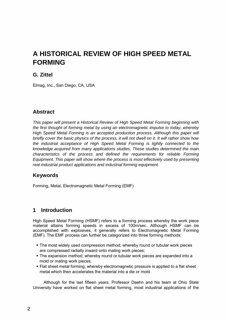
In the early 1960's, General Atomic in San Diego, while conducting nuclear fusion research, experienced material failures caused by the forces between current carrying conductors. The extremely high temperatures required for fusion research were produced by compressing an ionized gas with a high-intensity electromagnetic field. The currents required to generate the high-intensity fields were produced by discharging many parallel-connected capacitors into a coil. Parallel copper bus bars were used to carry the capacitor currents to the coil. These currents could reach magnitudes from several hundred thousands up to around one million Amperes. The opposing forces generated between the parallel plates bus bar system therefore exceeded the yield strength of the material causing it to fail and the conductors to bulge apart, as shown in Figure 1 below.
Figure 1: Bulges in parallel bus work due to electromagnet pressure
Someone then had the idea of using these “undesired” forces to perform useful
work. The bus bar system was transformed into a coil into which an electrical conductive
3
4th International Conference on High Speed Forming – 2010
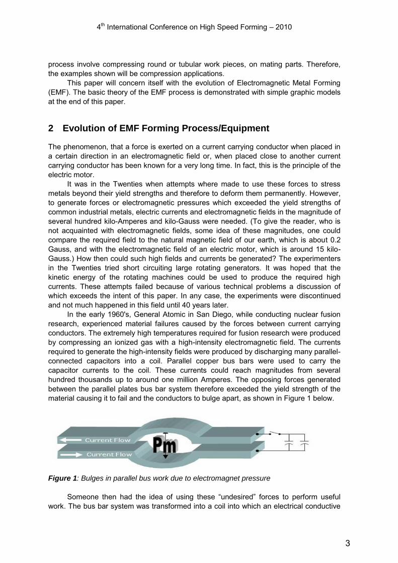
work piece would be inserted. The interaction of the field and induced current would exert pressure on the work piece. The set-up was primitive. However, the results of the following experiments were sufficiently encouraging to continue development of the process and equipment. This was the birth of what later developed into a widely applied new metal forming and assembly technology. The two pictures below, Figure 2a and 2b illustrate the concept of a typical coil with a work piece and one of the first coils with a re-enforcing case.
Figure 2a: Concept of EMF Coil and
Work Piece Figure 2b: First Compression Coil with a
re-enforcing Case
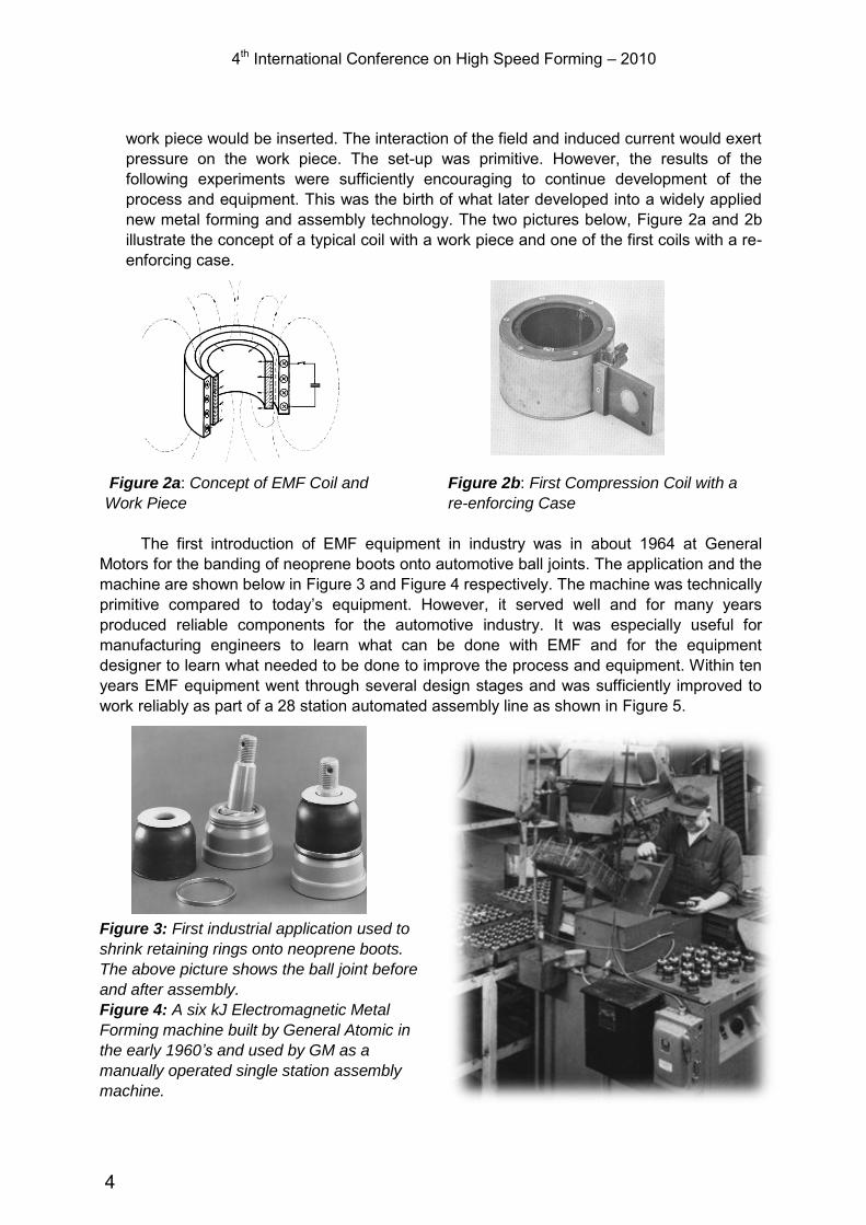
The first introduction of EMF equipment in industry was in about 1964 at General Motors for the banding of neoprene boots onto automotive ball joints. The application and the machine are shown below in Figure 3 and Figure 4 respectively. The machine was technically primitive compared to today’s equipment. However, it served well and for many years produced reliable components for the automotive industry. It was especially useful for manufacturing engineers to learn what can be done with EMF and for the equipment designer to learn what needed to be done to improve the process and equipment. Within ten years EMF equipment went through several design stages and was sufficiently improved to work reliably as part of a 28 station automated assembly line as shown in Figure 5.
Figure 3: First industrial application used to
shrink retaining rings onto neoprene boots.
The above picture shows the ball joint before
and after assembly.
Figure 4: A six kJ Electromagnetic Metal
Forming machine built by General Atomic in
the early 1960’s and used by GM as a
manually operated single station assembly
machine.
4
4th International Conference on High Speed Forming – 2010
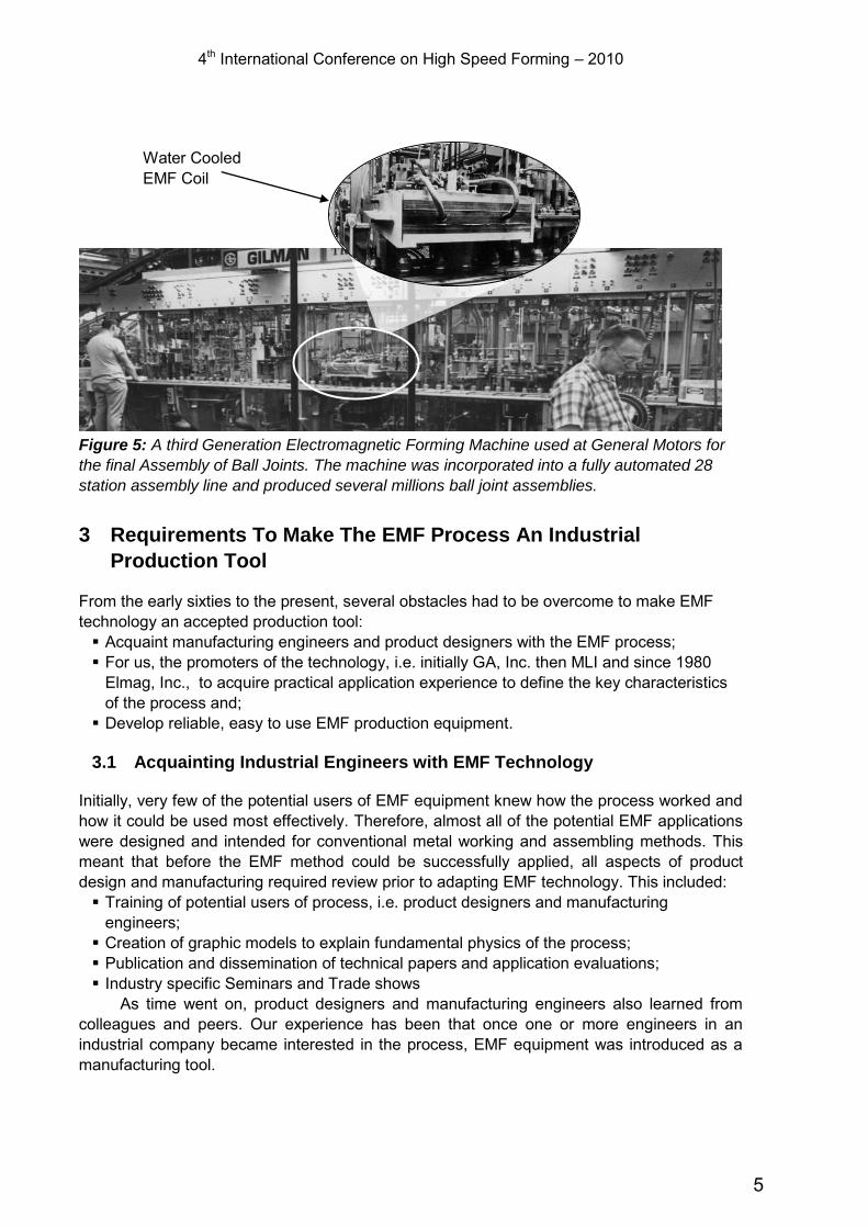
Figure 5: A third Generation Electromagnetic Forming Machine used at General Motors for
the final Assembly of Ball Joints. The machine was incorporated into a fully automated 28
station assembly line and produced several millions ball joint assemblies.
3 Requirements To Make The EMF Process An Industrial
Production Tool
From the early sixties to the present, several obstacles had to be overcome to make EMF technology an accepted production tool: Acquaint manufacturing engineers and product designers with the EMF process; For us, the promoters of the technology, i.e. initially GA, Inc. then MLI and since 1980
Elmag, Inc., to acquire practical application experience to define the key characteristics of the process and;
Develop reliable, easy to use EMF production equipment.
3.1 Acquainting Industrial Engineers with EMF Technology
Initially, very few of the potential users of EMF equipment knew how the process worked and how it could be used most effectively. Therefore, almost all of the potential EMF applications were designed and intended for conventional metal working and assembling methods. This meant that before the EMF method could be successfully applied, all aspects of product design and manufacturing required review prior to adapting EMF technology. This included: Training of potential users of process, i.e. product designers and manufacturing
engineers; Creation of graphic models to explain fundamental physics of the process; Publication and dissemination of technical papers and application evaluations; Industry specific Seminars and Trade shows
As time went on, product designers and manufacturing engineers also learned from colleagues and peers. Our experience has been that once one or more engineers in an industrial company became interested in the process, EMF equipment was introduced as a manufacturing tool.
Water Cooled EMF Coil
5
4th International Conference on High Speed Forming – 2010
3.2 Application Experience
We also had to learn about the practical and economic limitation of the process. In the early years, we as well as potential customers were so overly enthusiastic about this unique process that many times we attempted to solve problems with EMF which were just not suited for it. We simply had to learn to evaluate applications and not to pursue non-feasible applications. After years of studies and applied and basic research, we have acquired detailed knowledge of the basic properties and key characteristics of electromagnetic metal forming. This provided us the experience to efficiently evaluate the feasibility of most application inquiries. This experience also allowed us to summarize the Key Characteristics of the Process and disseminate them to potential users.
4 Key Characteristics of the Process
Although the EMF process is called a “metal forming process,” it is mostly, but not exclusively used as an assembly process: The method works best with materials having relatively high electrical conductivity,
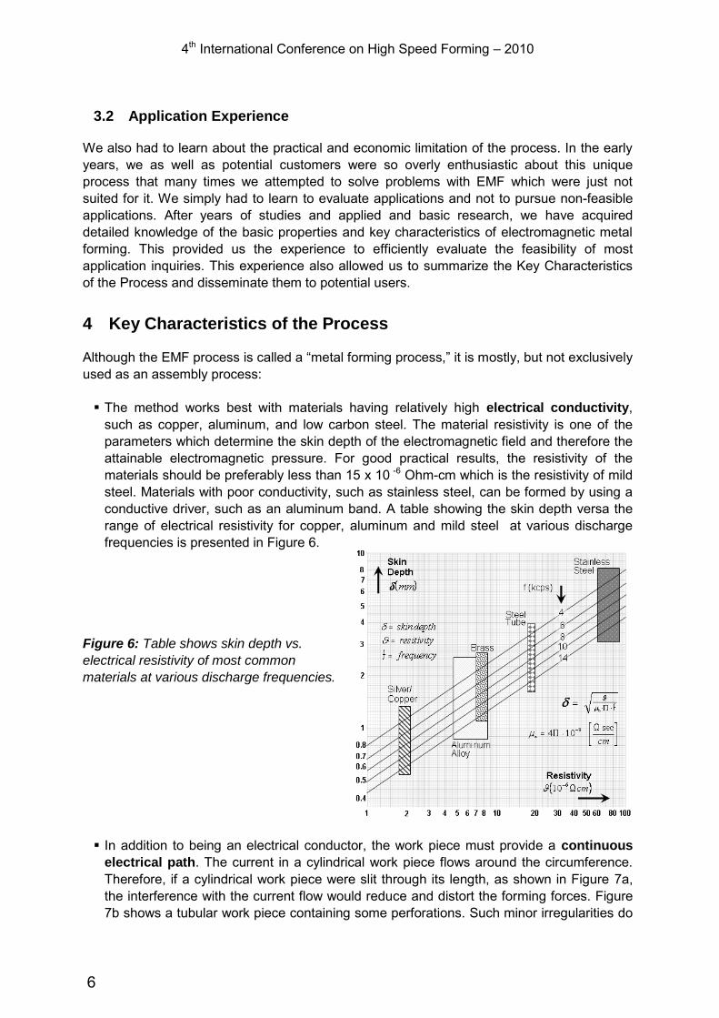
such as copper, aluminum, and low carbon steel. The material resistivity is one of the parameters which determine the skin depth of the electromagnetic field and therefore the attainable electromagnetic pressure. For good practical results, the resistivity of the materials should be preferably less than 15 x 10 -6 Ohm-cm which is the resistivity of mild steel. Materials with poor conductivity, such as stainless steel, can be formed by using a conductive driver, such as an aluminum band. A table showing the skin depth versa the range of electrical resistivity for copper, aluminum and mild steel at various discharge frequencies is presented in Figure 6.
Figure 6: Table shows skin depth vs.
electrical resistivity of most common
materials at various discharge frequencies.
In addition to being an electrical conductor, the work piece must provide a continuous
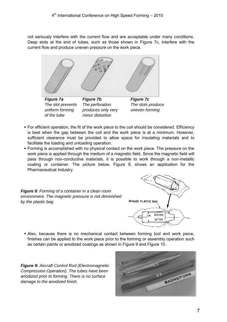
electrical path. The current in a cylindrical work piece flows around the circumference. Therefore, if a cylindrical work piece were slit through its length, as shown in Figure 7a, the interference with the current flow would reduce and distort the forming forces. Figure 7b shows a tubular work piece containing some perforations. Such minor irregularities do
6
4th International Conference on High Speed Forming – 2010
not seriously interfere with the current flow and are acceptable under many conditions. Deep slots at the end of tubes, such as those shown in Figure 7c, interfere with the current flow and produce uneven pressure on the work piece.
Figure 7a
The slot prevents
uniform forming
of the tube
Figure 7b
The perforation
produces only very
minor distortion
Figure 7c
The slots produce
uneven forming
For efficient operation, the fit of the work piece to the coil should be considered. Efficiency
is best when the gap between the coil and the work piece is at a minimum. However, sufficient clearance must be provided to allow space for insulating materials and to facilitate the loading and unloading operation.
Forming is accomplished with no physical contact on the work piece. The pressure on the work piece is applied through the medium of a magnetic field. Since the magnetic field will pass through non-conductive materials, it is possible to work through a non-metallic coating or container. The picture below, Figure 8, shows an application for the Pharmaceutical Industry.
Figure 8: Forming of a container in a clean room
environment. The magnetic pressure is not diminished
by the plastic bag
Also, because there is no mechanical contact between forming tool and work piece,
finishes can be applied to the work piece prior to the forming or assembly operation such as certain paints or anodized coatings as shown in Figure 9 and Figure 10.
Figure 9: Aircraft Control Rod (Electromagnetic
Compression Operation). The tubes have been
anodized prior to forming. There is no surface
damage to the anodized finish.
7
4th International Conference on High Speed Forming – 2010
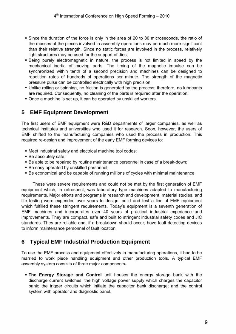
Figure 10: These anodized Platen for medical
instruments were expanded with electromagnetic
pressure into a mold.
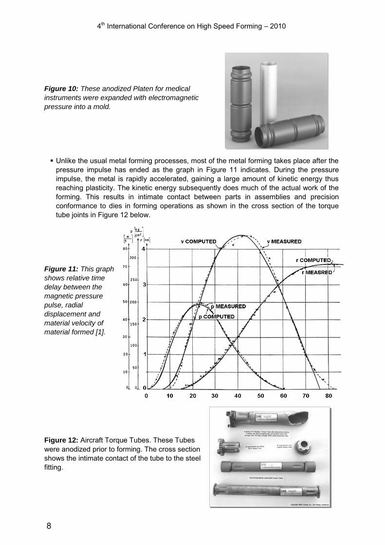
Unlike the usual metal forming processes, most of the metal forming takes place after the
pressure impulse has ended as the graph in Figure 11 indicates. During the pressure impulse, the metal is rapidly accelerated, gaining a large amount of kinetic energy thus reaching plasticity. The kinetic energy subsequently does much of the actual work of the forming. This results in intimate contact between parts in assemblies and precision conformance to dies in forming operations as shown in the cross section of the torque tube joints in Figure 12 below.
Figure 11: This graph
shows relative time
delay between the
magnetic pressure
pulse, radial
displacement and
material velocity of
material formed [1].
Figure 12: Aircraft Torque Tubes. These Tubes were anodized prior to forming. The cross section shows the intimate contact of the tube to the steel fitting.
8
4th International Conference on High Speed Forming – 2010 Since the duration of the force is only in the area of 20 to 80 microseconds, the ratio of
the masses of the pieces involved in assembly operations may be much more significant than their relative strength. Since no static forces are involved in the process, relatively light structures may be used for the support of dies;
Being purely electromagnetic in nature, the process is not limited in speed by the mechanical inertia of moving parts. The timing of the magnetic impulse can be synchronized within tenth of a second precision and machines can be designed to repetition rates of hundreds of operations per minute. The strength of the magnetic pressure pulse can be controlled electrically with high precision;
Unlike rolling or spinning, no friction is generated by the process; therefore, no lubricants are required. Consequently, no cleaning of the parts is required after the operation;
Once a machine is set up, it can be operated by unskilled workers.
5 EMF Equipment Development
The first users of EMF equipment were R&D departments of larger companies, as well as technical institutes and universities who used it for research. Soon, however, the users of EMF shifted to the manufacturing companies who used the process in production. This required re-design and improvement of the early EMF forming devices to: Meet industrial safety and electrical machine tool codes; Be absolutely safe; Be able to be repaired by routine maintenance personnel in case of a break-down; Be easy operated by unskilled personnel; Be economical and be capable of running millions of cycles with minimal maintenance
These were severe requirements and could not be met by the first generation of EMF
equipment which, in retrospect, was laboratory type machines adapted to manufacturing requirements. Major efforts and programs in research and development, material studies, and life testing were expended over years to design, build and test a line of EMF equipment which fulfilled these stringent requirements. Today’s equipment is a seventh generation of EMF machines and incorporates over 40 years of practical industrial experience and improvements. They are compact, safe and built to stringent industrial safety codes and JIC standards. They are reliable and, if a breakdown should occur, have fault detecting devices to inform maintenance personnel of fault location.
6 Typical EMF Industrial Production Equipment
To use the EMF process and equipment effectively in manufacturing operations, it had to be married to work piece handling equipment and other production tools. A typical EMF assembly system consists of three major components- The Energy Storage and Control unit houses the energy storage bank with the
discharge current switches; the high voltage power supply which charges the capacitor bank; the trigger circuits which initiate the capacitor bank discharge; and the control system with operator and diagnostic panel.
9
4th International Conference on High Speed Forming – 2010
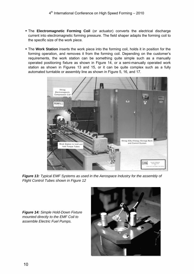
The Electromagnetic Forming Coil (or actuator) converts the electrical discharge current into electromagnetic forming pressure. The field shaper adapts the forming coil to the specific size of the work piece.
The Work Station inserts the work piece into the forming coil, holds it in position for the
forming operation, and removes it from the forming coil. Depending on the customer’s
requirements, the work station can be something quite simple such as a manually operated positioning fixture as shown in Figure 14, or a semi-manually operated work station as shown in Figures 13 and 15, or it can be quite complex such as a fully automated turntable or assembly line as shown in Figure 5, 16, and 17.
Figure 13: Typical EMF Systems as used in the Aerospace Industry for the assembly of
Flight Control Tubes shown in Figure 12
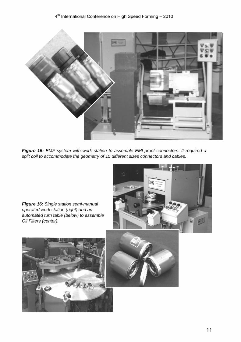
Figure 14: Simple Hold-Down Fixture
mounted directly to the EMF Coil to
assemble Electric Fuel Pumps.
10
4th International Conference on High Speed Forming – 2010
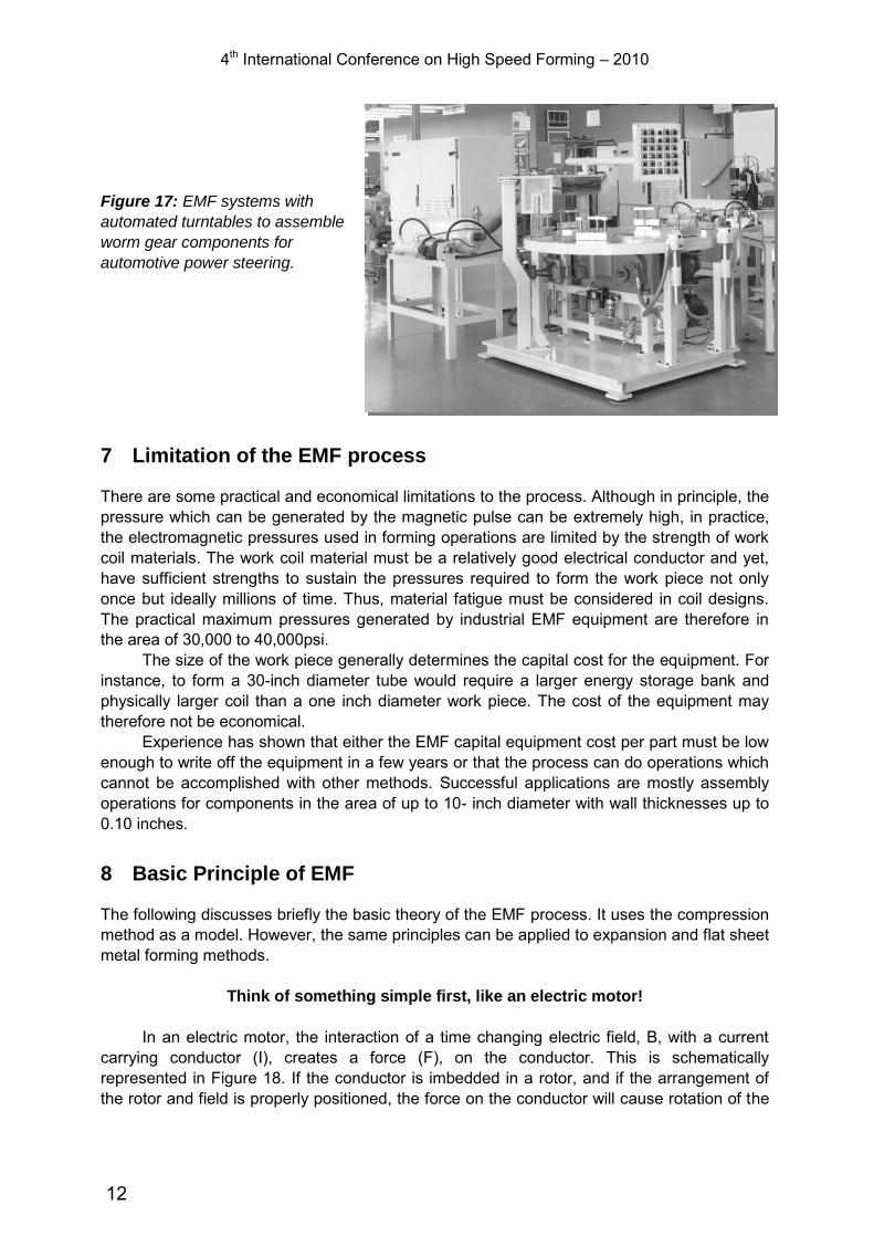
Figure 15: EMF system with work station to assemble EMI-proof connectors. It required a
split coil to accommodate the geometry of 15 different sizes connectors and cables.
Figure 16: Single station semi-manual
operated work station (right) and an
automated turn table (below) to assemble
Oil Filters (center).
11
4th International Conference on High Speed Forming – 2010
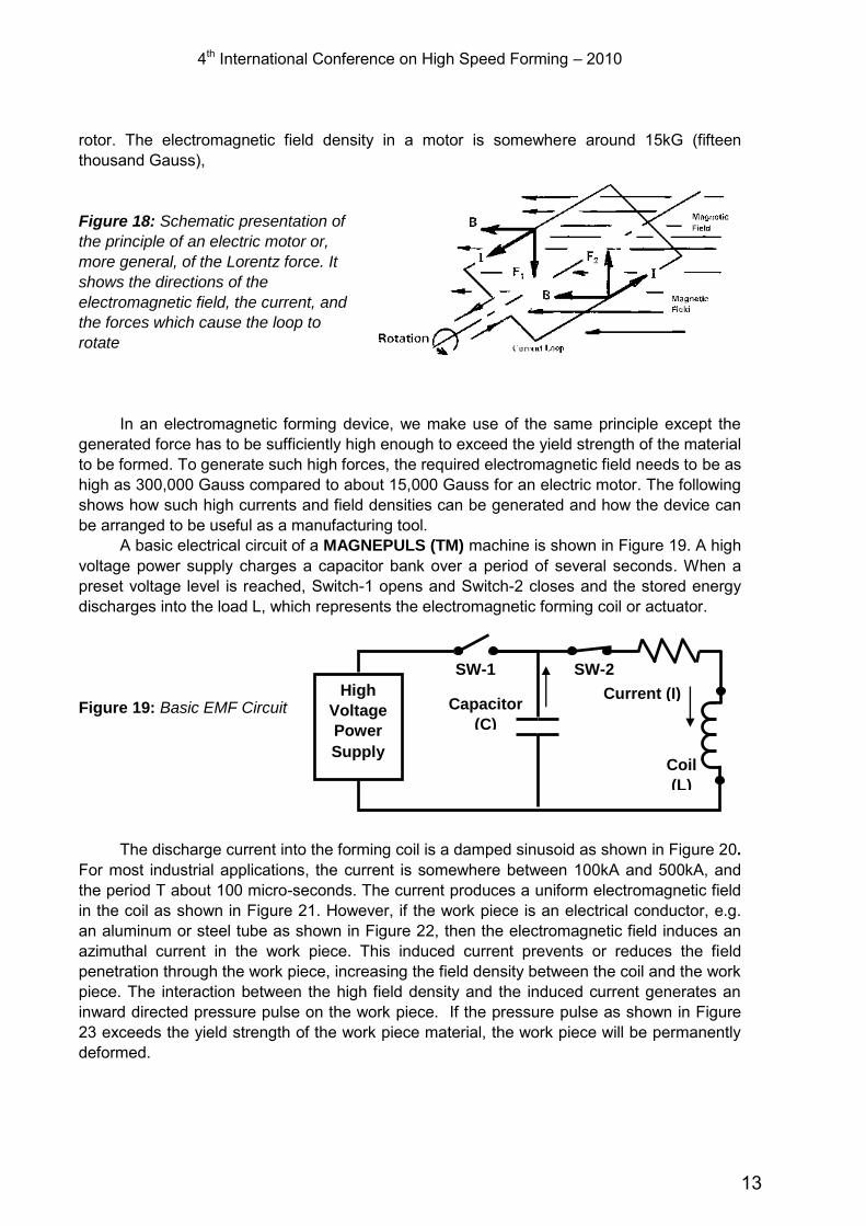
Figure 17: EMF systems with
automated turntables to assemble
worm gear components for
automotive power steering.
7 Limitation of the EMF process
There are some practical and economical limitations to the process. Although in principle, the pressure which can be generated by the magnetic pulse can be extremely high, in practice, the electromagnetic pressures used in forming operations are limited by the strength of work coil materials. The work coil material must be a relatively good electrical conductor and yet, have sufficient strengths to sustain the pressures required to form the work piece not only once but ideally millions of time. Thus, material fatigue must be considered in coil designs. The practical maximum pressures generated by industrial EMF equipment are therefore in the area of 30,000 to 40,000psi.
The size of the work piece generally determines the capital cost for the equipment. For instance, to form a 30-inch diameter tube would require a larger energy storage bank and physically larger coil than a one inch diameter work piece. The cost of the equipment may therefore not be economical.
Experience has shown that either the EMF capital equipment cost per part must be low enough to write off the equipment in a few years or that the process can do operations which cannot be accomplished with other methods. Successful applications are mostly assembly operations for components in the area of up to 10- inch diameter with wall thicknesses up to 0.10 inches.
8 Basic Principle of EMF
The following discusses briefly the basic theory of the EMF process. It uses the compression method as a model. However, the same principles can be applied to expansion and flat sheet metal forming methods.
Think of something simple first, like an electric motor!
In an electric motor, the interaction of a time changing electric field, B, with a current
carrying conductor (I), creates a force (F), on the conductor. This is schematically represented in Figure 18. If the conductor is imbedded in a rotor, and if the arrangement of the rotor and field is properly positioned, the force on the conductor will cause rotation of the
12
4th International Conference on High Speed Forming – 2010 rotor. The electromagnetic field density in a motor is somewhere around 15kG (fifteen thousand Gauss), Figure 18: Schematic presentation of
the principle of an electric motor or,
more general, of the Lorentz force. It
shows the directions of the
electromagnetic field, the current, and
the forces which cause the loop to
rotate
In an electromagnetic forming device, we make use of the same principle except the generated force has to be sufficiently high enough to exceed the yield strength of the material to be formed. To generate such high forces, the required electromagnetic field needs to be as high as 300,000 Gauss compared to about 15,000 Gauss for an electric motor. The following shows how such high currents and field densities can be generated and how the device can be arranged to be useful as a manufacturing tool.
A basic electrical circuit of a MAGNEPULS (TM) machine is shown in Figure 19. A high voltage power supply charges a capacitor bank over a period of several seconds. When a preset voltage level is reached, Switch-1 opens and Switch-2 closes and the stored energy discharges into the load L, which represents the electromagnetic forming coil or actuator.
Figure 19: Basic EMF Circuit
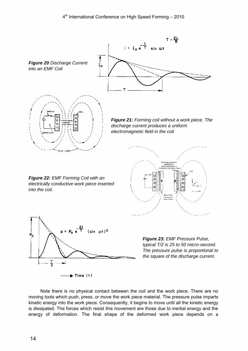
The discharge current into the forming coil is a damped sinusoid as shown in Figure 20.
For most industrial applications, the current is somewhere between 100kA and 500kA, and the period T about 100 micro-seconds. The current produces a uniform electromagnetic field in the coil as shown in Figure 21. However, if the work piece is an electrical conductor, e.g. an aluminum or steel tube as shown in Figure 22, then the electromagnetic field induces an azimuthal current in the work piece. This induced current prevents or reduces the field penetration through the work piece, increasing the field density between the coil and the work piece. The interaction between the high field density and the induced current generates an inward directed pressure pulse on the work piece. If the pressure pulse as shown in Figure 23 exceeds the yield strength of the work piece material, the work piece will be permanently deformed.
High
Voltage
Power
Supply
SW-1 SW-2
Current (I) Capacitor
(C)
Coil
(L)
13
4th International Conference on High Speed Forming – 2010
Figure 20 Discharge Current
into an EMF Coil
Figure 21: Forming coil without a work piece. The
discharge current produces a uniform
electromagnetic field in the coil
Figure 22: EMF Forming Coil with an
electrically conductive work piece inserted
into the coil.
Figure 23: EMF Pressure Pulse,
typical T/2 is 25 to 50 micro-second.
The pressure pulse is proportional to
the square of the discharge current.
Note there is no physical contact between the coil and the work piece. There are no
moving tools which push, press, or move the work piece material. The pressure pulse imparts kinetic energy into the work piece. Consequently, it begins to move until all the kinetic energy is dissipated. The forces which resist this movement are those due to inertial energy and the energy of deformation. The final shape of the deformed work piece depends on a
14

4th International Conference on High Speed Forming – 2010 combination of factors. These are the magnitude of the pressure pulse, the strength and geometry of the work piece, and the shape and geometry of a mating part such as a die or a mandrel, or a second work piece. Figure 24 shows a tube formed onto a fitting. Notice how the tube practically wraps itself around the contours of the fitting.
Figure 24: Tube formed onto a fitting. Notice
how tightly the tube wraps around the mating
plug. This is because of the high forming
speed which turns the material plastic.
To adapt the coil to different work piece diameters and to concentrate the pressure pulse in particular areas, one makes use of a flux transfer member, also called a flux concentrator or a field shaper as shown in Figure 25.
Figure 25: This illustration shows a field shaper
which concentrates the pressure in two areas,
indicated as A.
9 Conclusion
The foregoing has shown that as a result of an incidental nuisance, a known principle in physics found a new application in industry. With efforts in research and development, it was transformed into a unique and widely accepted manufacturing technology; The Acceptance by Industry of the EMF Technology was directly related to the
improvement in reliability and safety of the EMF equipment; EMF Technology is unique and allows product designs which cannot be solved with
conventional processes. Yet, it does not replace them but rather complements them.
Reference
[1] Hansjorg Jansen: Some Measurements Of The Expansion of A Metallic Cylinder With Electromagnetic Pulses. IEEE Transaction On Industry And General Applications. July/August 1968
15