a home device for vestibular stimulation
TRANSCRIPT

A HOME DEViCE fOR VESTibULAR STiMULATiON
David w. Dyk, Student Author Partnered with Victoria Drake, Patrick wallis, and Gregg baker
Dr. brian P. Self, Research Advisor
EXECUTiVE SUMMARY The goal of this project, which was presented to the team by Kevin Maher
(President of Advanced Therapeutic devices), was to develop a product pro
totype for safe, vestibular stimulation for children with developmental dis
abilities. Vestibular stimulation is a form of therapy that increases muscle
coordination. It works by stimulating the canals and sacs within the inner
ear that detect accelerations. The project targeted children from ages two to
seven years old, under 48 inches tall, and less than 100 lbs. The production
device also sought to differ from stimulation devices found in hospitals in a
few respects: it would cost under $5000, reside in a patient’s home, be hand-
powered, and be controlled by an average person. The final device needed to
support a 200 lb. load at the edge of the structure and adjust for the center of
gravities for the range of children.
After sessions of brainstorming, the team produced three workable layouts,
only one was adequate. The final setup had a structure of ¼ in. aluminum
structural pipe similar to a football field goal. This structure mounted on
a single bearing housing and steel shaft. The final design had two bars to
mount weights in order to adjust the center of gravity. The prototype, how
ever, used a swinging bar, lock, and a sliding weight. The final prototype had
an adjustable footrest and a five-point restraint harness. The final cost and
weight was $1700 and no more than 500 lb. The design met all of the require
ments and had adequate safety for any child’s needs, but the team thought
the design needed significant changes before it became a final product.
HONORS JOURNAL 2008 65

iNTRODUCTiON This report discusses the results of research, design, and construction of a
device for vestibular stimulation. The final results come from one quarter of
design and one quarter of building the prototype.
The vestibular stimulation project began with Gregg Baker and Victoria
Drake. The two senior design students received this vestibular stimulation
project from Kevin Maher, President of Advanced Therapeutic Devices (ATD).
He desired a cheap, safe, and reliable system for delivering vestibular stimu
lation, since children with developmental disabilities have generally shown
improvements in areas such as muscle coordination after receiving this sort
of treatment. This actual process of vestibular stimulation will be discussed
in greater detail later in this report.
Kevin Maher wanted a human-powered, vestibular stimulation device
different than others found in hospitals. These different motor-powered ver
sions cost a large sum of money and cannot be easily installed in a person’s
home. Maher asked the team to design a more practical, human-powered
version that costs less, resides in a person’s home, and provides the same
treatment. He imagined the prototype would serve as a starting point for a
production product.
This prototype needed to meet these general requirements:
• Provide for the child’s safety
• Have adequate comfort
• Cost under $5000
• Have a fairly simple assembly
• Fit within a common home
• Ship in small, few, low-weight parts
• Require minimal effort to rotate
• Be easily controlled by an average person
• Adjust for a range of children’s sizes
• Produce minimal noise and vibrations
• Rotate about both a vertical and horizontal axis
The chair aimed to accommodate children from ages two to seven years
old, up to 100lbs., less than 48 inches tall, and the group assumed the par
66 STUDENT RESEARCH

ents would rotate the chair for the children. In addition, Maher required that
the prototype sustain a 200 lb. load at the farthest side of the structure. The
group set the cost requirement at $5000 since the motorized stimulation
devices found in hospitals can cost more than five times that amount. The
team also saw through research that the chair needed to rotate in a certain
manner to provide adequate stimulation.
I joined the team to assist in the design, manufacturing, and research
as part of the Honors Research Program. Patrick Wallis joined the group to
provide manufacturing experience and more insight into the design of the
vestibular stimulation device. The whole team worked together to design and
construct the device that would stimulate a child’s vestibular system.
The following sections of this report follow the basic process of design and
testing. The background research into the vestibular system and its stimula
tion gives essential information on what the device will accomplish. From
this research, the group developed many ideas, but decided on a single appli
cation. Next, the team finalized the design with estimations of the criteria
(cost, forces and moments, weight, dimensions, comfort, and safety). The
final structural layout went into prototype production, which went through
a short phase of testing. After observing the model device at work, the group
found that it satisfied all of the basic requirements, but thought it was too
complicated a structure for a production model.
bACKGROUND Of THE VESTibULAR SYSTEM In order to gain a better understanding of the design requirements, the team
gathered research about the vestibular stimulation process to understand how
the vestibular system senses motion during both linear and angular accelera
tion. This went to help the device achieve the best results.The group learned
that the vestibular system gives the sense of all accelerations in addition to
the five senses of taste, touch, hearing, smell, and sight. This bodily system
sits in the inner ear and has two parts, one for the sense for angular accelera
tion (or rotation) and another for the sense of linear acceleration.
The first set of organs, the three canals in the inner ear, detects angular
acceleration (see Figure 1). The posterior, horizontal, and superior (or ante-
HONORS JOURNAL 2008 67
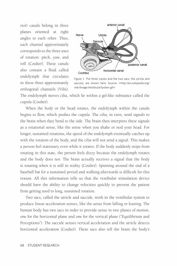
rior) canals belong in three
planes oriented at right
angles to each other. Thus,
each channel approximately
corresponds to the three axes
of rotation: pitch, yaw, and
roll (Coulter). These canals
also contain a fluid called
endolymph that circulates
in these three approximately
orthogonal channels (Vilis).
The endolymph moves cilia, which lie within a gel-like substance called the
cupula (Coulter).
When the body or the head rotates, the endolymph within the canals
begins to flow, which pushes the cupula. The cilia, in turn, send signals to
the brain when they bend to the side. The brain then interprets these signals
as a rotational sense, like the sense when you shake or nod your head. For
longer, sustained rotations, the speed of the endolymph eventually catches up
with the rotation of the body, and the cilia will not send a signal. This makes
a person feel stationary even while it rotates. If the body suddenly stops from
rotating in this state, the person feels dizzy because the endolymph rotates
and the body does not. The brain actually receives a signal that the body
is rotating when it is still in reality (Coulter). Spinning around the end of a
baseball bat for a sustained period and walking afterwards is difficult for this
reason. All this information tells us that the vestibular stimulation device
should have the ability to change velocities quickly to prevent the patient
from getting used to long, sustained rotation.
Two sacs, called the utricle and saccule, work in the vestibular system to
produce linear acceleration senses, like the sense from falling or leaning. The
human body has two sacs in order to provide sense in two planes of motion,
one for the horizontal plane and one for the vertical plane (“Equilibrium and
Perceptions”). The saccule senses vertical acceleration and the utricle detects
horizontal acceleration (Coulter). These sacs also tell the brain the body’s
figure 1. The three canals and the two sacs, the utricle and
saccule, are shown here. Source: <http://en.wikipedia.org/
wiki/image:VestibularSystem.gif>
68 STUDENT RESEARCH

direction relative to gravity, or in other words, which way is up. The stimula
tion of each sac happens in a similar way to the semi-circular canals. When
a gelatinous substance and ear stones in the sacs move nerves, the nerves
become stimulated and send a signal to the brain (Vilis).
So what does this all do for the body? Basically, the vestibular system
helps a person know about balance, motion, and body position (Coulter). The
two components of the vestibular system help with motor coordination and
stimulate muscles to keep posture (“Equilibrium and Perceptions”). Also, the
two sets of canals in either ear work together to stimulate eye muscles so a
person can focus even while the head rotates. This reflex is called vestibular
ocular reflex, or VOR (“Equilibrium and Perceptions”).
The team’s vestibular stimulation device will excite the vestibular system
and develop all of these vestibular functions. Some research has shown that
this stimulation can help development of many different body functions, one
of which is motor coordination. Some therapists have already implemented
this sort of stimulation and observesd somewhat positive results in some
patients’ development (Ardent). Still, the patients needing these devices can
not afford motor-driven versions of their own and must make frequent trips
to hospitals for treatment. The vestibular stimulation prototype the team
designed can get the same results without the motor, with less cost, and also
remain in a patient’s home.
A wide variety of people have shown vestibular dysfunction. An examiner
could notice vestibular problems in people with dyslexia, “…schizophrenia,
autism, psychosis, behavior disorders, Down’s Syndrome, minor neurological
impairment, hyperactivity, communication disorders, adolescent idiopathic
scoliosis, multiple sclerosis, cerebral vascular accidents, mental retardation,
developmental delay, otitis media, and Parkinson’s disease” (Greg). The final
vestibular stimulation prototype aims to help children with these kinds of
disorders.
In “Vestibular Stimulation as a Form of Therapy,” Kelly Greg discussed the
optimum configuration for a vestibular stimulation device that would help
the people with the aforementioned disabilities. She noted a child needs rapid
accelerations for high stimulation. If the stimulation system moves slowly and
HONORS JOURNAL 2008 69

repetitively, it could actually have an inhibitory effect. In addition, different
directions of rotation excite different canals and the utricle and saccule expe
rience the most stimulation when upside down. Greg also stated the patient
must experience constant velocity rotation for at least one minute before com
ing to rest to achieve maximum stimulation. If a constant velocity lasts less
than a minute, the fluid in the semi-circular canals return too quickly to the
resting state. The team kept all these requirements in mind while completing
the design of the prototype.
SUGGESTiONS Of DESiGN The vestibular stimulation team came up with many ideas on methods of
delivering the therapy. For some ideas, the group built upon the strengths
of Kevin Maher’s prototypes. In other cases, ideas broke away from conven
tional concepts in order to produce a sufficient solution. In the end, only a
few concepts looked like real possibilities. The more practical concepts are
shown in Figures 2-4.
Each idea had its own problems and advantages. Some, like the “concentric
circle” design in Figure 2, would provide fast rotation, but had inherently dan
gerous characteristics. Also, some concepts would operate in a sort of unpre
dictable motion, which would pose a big problem for the controlled stimu
lation that the problem required. The team also noted the ideas that would
have the most frictional losses and those with a good amount of comfort.
After discussions with Maher,
the group chose the second idea
(Figure 3), a vertically oriented
chair that rotates about a hori
zontal axis on a rotating base.
This application offered struc
tural stability, simplicity, com
fort, and good overall control of
the motion. figure 2. The first design concept has two concentric
circles for two axes.
70 STUDENT RESEARCH

METHODS Of DESiGN The majority of the team’s design work came from research on components,
ideas on application of these components, and calculations. Since this device
did not have any predecessors to follow, aside from Kevin Maher’s small pro
totypes and experience, the group relied on innovation.
A few factors played major roles in detailing the idea. These held the focus
of the group during the design:
• Friction within the base
• Variable center of gravity
• Structural loads and moments
For details, such as the
size of piping, shaft diam
eter, and other specifications,
Gregg Baker and Victoria
Drake performed calculations
in order to find more specific
external load requirements.
They found statistics on loads figure 3. Concept two is more basic and simple than
on the piping, pipe fittings, the other ideas.
bearing housing, and base.
These calculations helped
the project meet its goals. For
example, Baker found that
the base (with the appropriate
structural dimensions) sup
ported a 200 lb. load at the figure 4. Concept three has possibilities, but would be
uncomfortable. edge of the structure, resisted
falling over from the resulting
400 ft-lb moment, and sustained a 75 lb. force 4 ft. above the base.
As research, ideas, and specifics developed, the team updated SolidWorks
drawings in order to visualize the prototype’s layout. Once the team built the
prototype, it went through a series of tests. In addition, the prototype con-
HONORS JOURNAL 2008 71

firmed the center of gravity calculations. Finally, loads at points of interest
confirmed the soundness of the structure.
fiNAL DESiGN The final design, illustrated in the attached appendix, meets all of the
requirements for a successful home vestibular device (please refer to the
appendix to clarify the layout of the assemblies mentioned in this section).
Some of the highlights of the structure include an adjustable restraint and
footrest, an adjustable center of gravity, good safety, light components, and
compact design.
The basic support structure follows a sort of field goal shape. This offered
the best solution to the frictional problem. With rollers, a person driving the
device would exert too much effort, but with a single, central housing, the
device rotates freely. The base has 5 four-foot struts mounted to the bearing
housing with half-inch bolts. The base also uses 1.5 inch diameter structural
aluminum tubing for the support structure, which connects with aluminum
pipe fittings pre-drilled for a set screw. The other side of the pipe fitting has
drilled holes to lock together with the tubing by a bolt.
The seat needed adjustability, comfort, and rigidity. The chair itself has a
plywood back and is supported by T-slot structural members. The plywood
provides adequate support while T-slots allow an assembler to easily bracket
the entire structure together. The chair has two angled slots with an adjustable
shoulder height to accommodate children of different heights and shoulder
widths. The restraint system is a five-point harness, which provides excellent
safety. The fact that this harness can be found on a few children’s car seats
speaks to its security. This five-point harness tightens by a single belt that
passes under the seat into a locking mechanism. This allows the seat to secure
quickly and with minimal effort, which posed a concern earlier in the design.
The chair sides have 2 four-foot diameter plywood disks mounted on each
side of the chair in order to keep the child’s arms from moving outside the
chair. They also help a caregiver propel the chair with minimal effort and
without safety problems. The high-quality plywood disks have no dangerous
gaps, rough edges, or open holes.
72 STUDENT RESEARCH

The bearing housing is the most critical piece in the design. It supports
the 400 ft-lb moment for the two bearings held within it and it allows the
entire structure to turn freely. This critical piece holds the bearings and the
lathed shaft securely. The bearings themselves sit on the stepped shaft, which
attaches to the pipe fitting at the center of the chair’s support structure. The
housing has a flange with 10 points of attachment for the base struts and this
flange has a weld on one side to attach to the bearing housing. Destruction
testing of the weld showed that it exceeded the strength requirements for the
structure.
The most difficult task presented to the team was the adjustable center of
gravity. To accommodate for all the different positions of the target child, the
design specifies T-slots behind and below the chair that span the distance
between the two disks. The team originally planned for a person to simply
strap added weights to these bars in order to shift the center of gravity in line
with the axis of rotation. However, this design characteristic changed after
we constructed and tested the actual prototype.
PROTOTYPE CONSTRUCTiON AND RESULTS During the second quarter of this project, the group constructed a prototype
to test the final design and to demonstrate that the actual product met the
given requirements. The team encountered a few problems, but eventually
ended up with a result similar to the original layout.
First, T-slots are relatively simple to put together, but they have a couple
major problems. The T-slots ended up being the most expensive component
on the structure. Furthermore, the advantage of using T-slots was also their
biggest nuisance. T-slots do not require much cutting, welding, or drilling,
but they need countless screws and nuts to hold them together. The complex
framework posed a tedious task of assembly, even for the team—the actual
designers. A user of this chair would have an even harder time trying to
assemble it. The extensive T-slot chair frame may be just too convoluted and
expensive to suit a production model.
However, the harness succeeded in providing good restraint. It secured
some test weights well and even safely held one child during rotation about
HONORS JOURNAL 2008 73
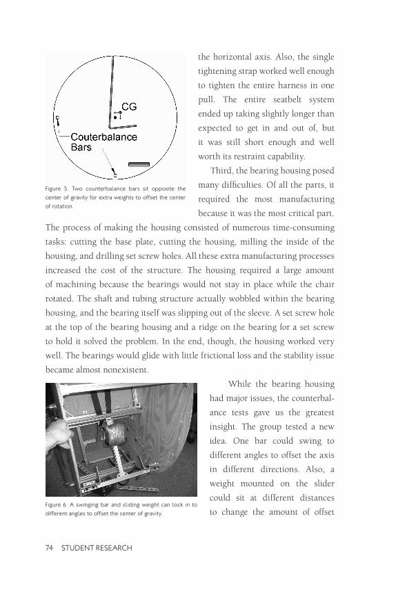
figure 5. Two counterbalance bars sit opposite the
center of gravity for extra weights to offset the center
of rotation.
the horizontal axis. Also, the single
tightening strap worked well enough
to tighten the entire harness in one
pull. The entire seatbelt system
ended up taking slightly longer than
expected to get in and out of, but
it was still short enough and well
worth its restraint capability.
Third, the bearing housing posed
many difficulties. Of all the parts, it
required the most manufacturing
because it was the most critical part.
The process of making the housing consisted of numerous time-consuming
tasks: cutting the base plate, cutting the housing, milling the inside of the
housing, and drilling set screw holes. All these extra manufacturing processes
increased the cost of the structure. The housing required a large amount
of machining because the bearings would not stay in place while the chair
rotated. The shaft and tubing structure actually wobbled within the bearing
housing, and the bearing itself was slipping out of the sleeve. A set screw hole
at the top of the bearing housing and a ridge on the bearing for a set screw
to hold it solved the problem. In the end, though, the housing worked very
well. The bearings would glide with little frictional loss and the stability issue
became almost nonexistent.
While the bearing housing
had major issues, the counterbal
ance tests gave us the greatest
insight. The group tested a new
idea. One bar could swing to
different angles to offset the axis
in different directions. Also, a
weight mounted on the slider
could sit at different distances
to change the amount of offset figure 6. A swinging bar and sliding weight can lock in to
different angles to offset the center of gravity.
74 STUDENT RESEARCH
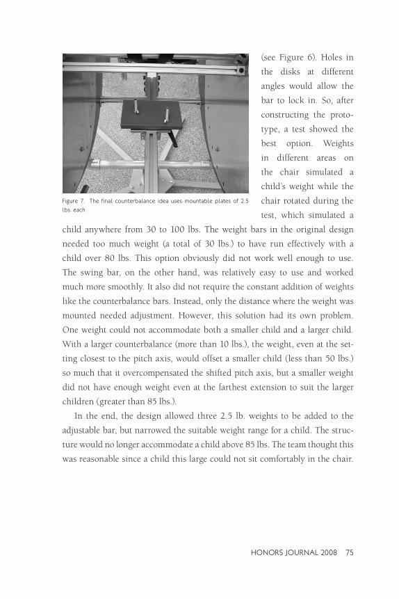
figure 7. The final counterbalance idea uses mountable plates of 2.5
lbs. each
(see Figure 6). Holes in
the disks at different
angles would allow the
bar to lock in. So, after
constructing the proto
type, a test showed the
best option. Weights
in different areas on
the chair simulated a
child’s weight while the
chair rotated during the
test, which simulated a
child anywhere from 30 to 100 lbs. The weight bars in the original design
needed too much weight (a total of 30 lbs.) to have run effectively with a
child over 80 lbs. This option obviously did not work well enough to use.
The swing bar, on the other hand, was relatively easy to use and worked
much more smoothly. It also did not require the constant addition of weights
like the counterbalance bars. Instead, only the distance where the weight was
mounted needed adjustment. However, this solution had its own problem.
One weight could not accommodate both a smaller child and a larger child.
With a larger counterbalance (more than 10 lbs.), the weight, even at the set
ting closest to the pitch axis, would offset a smaller child (less than 50 lbs.)
so much that it overcompensated the shifted pitch axis, but a smaller weight
did not have enough weight even at the farthest extension to suit the larger
children (greater than 85 lbs.).
In the end, the design allowed three 2.5 lb. weights to be added to the
adjustable bar, but narrowed the suitable weight range for a child. The struc
ture would no longer accommodate a child above 85 lbs. The team thought this
was reasonable since a child this large could not sit comfortably in the chair.
HONORS JOURNAL 2008 75

In conclusion, the team would like to change only a couple things about
the prototype:
1. Replace the T-slots.
The chair takes a long enough time to construct without them. The numerous components of the T-slots were the biggest cost for our prototype.
2. Adjust the seat structure.
Originally, the group did not consider using counterweights. Because of this, the chair ended up being more complex than necessary. In fact, a manufactured chair that mounted between the disks might substitute for our whole chair structure. A manufactured chair would save cost, reduce weight, cut construction time, and increase simplicity of the structure.
CONCLUSiON The final design gives more than adequate vestibular stimulation to children
two to seven years old. It also has subassembly parts that weigh less than
40 lbs., so each part can ship easily. The total weight of the system does not
exceed 500 lbs. The device’s total estimated cost sits at $1700, but the vast
amounts of machining required for each part could increase the cost of labor.
The team’s prototype cost $2,600, but that includes parts and test weights
that a production model would not use.
The final design also meets all of the requirements set forth earlier. It pro
vides for adequate safety, suits a child’s needs, and provides a workable solu
tion to the center of gravity problem. Despite the success of the prototype,
the design should have significant modifications in order to make a reason
able production system.
ACKNOwLEDGMENTS A big thank you is due to both Dr. Brian Self and Kevin Maher, for their valu
able insight and guidance. This project would not have gotten as far as it did
without their input.
76 STUDENT RESEARCH

REfERENCES Arendt RE, MacLean WE Jr, Halpern LF, Youngquist GA, Baumeister AA. “The influence of
rotary vestibular stimulation upon motor development of nonhandicapped and Down syndrome infants.” Research in Developmental Disabilities. Volume 12, Issue 3, 1991. Abstract received 24 January 2007 from PubMed database. http://www.pubmed.gov/
Coulter, Gary and Gregory Vogt. “The Effects of Space Flight on the Human Vestibular System” NASA: Exploration Systems Directorate Education Outreach. 2002. Last accessed on 7 March 2007. http://weboflife.ksc.nasa.gov/pdf/vbrief.pdf
Kelly, Greg. “Vestibular Stimulation as a Form of Therapy.” Physiotherapy. Vol. 75, no. 3. March 1989. 5 February 2007. p 136-140.
“The Equilibrium and the Perceptions of Gravity.” Atlas of Human Anatomy. Giunti Editorial Group, Florence: 2006. pp. 99-100.
Vilis, Tutis. “The Physiology of the Senses: Lecture 10 – Balance.” University of Western Ontario. 8 Aug. 2006. Last accessed on 24 Jan. 2007. <http://www.physpharm.fmd.uwo. ca/undergrad/sensesweb/L10Balance/L10Balance.pdf>
APPENDiX The following pictures illustrate the final design of the vestibular stimulation
device prototype. These pictures do not represent changes made while con
structing the prototype, such as the swing bar for a counterbalance weight.
HONORS JOURNAL 2008 77

APPENDiX CONTiNUED
78 STUDENT RESEARCH

HONORS JOURNAL 2008 79

80 STUDENT RESEARCH