a human-like approach to footstep planning
TRANSCRIPT

15
A Human-Like Approach to Footstep Planning
Yasar Ayaz1,2, Khalid Munawar1, Mohammad Bilal Malik1,Atsushi Konno2
and Masaru Uchiyama2
1National University of Sciences and Technology (NUST), 2Tohoku University 1Pakistan, 2Japan
1. Introduction
Terrains in our everyday environment such as homes and offices are custom-designed for biped walkers i.e., human beings. Evolution of humanoid robots was, thus, a natural development in the field of mobile robotics. However, giving legs to a robot instead of wheels gives it a lot more than just resemblance to a human being. Unlike ordinary mobile robots, humanoids have the ability to cross obstacles by stepping over and upon them. This ability is left unexploited if the algorithms used for ordinary mobile robot navigation among obstacles are employed for humanoids too. Various approaches have been adopted in order to address this problem in the past. (McGhee & Iswandhi, 1979) developed a method that divides the terrain into ‘permissible’and ‘impermissible’ stepping positions. Keeping in view the direction in which the ultimate goal position is located, the robot selects the next foothold from amongst the permissible ones in the immediately reachable footholds while taking care of postural stability constraints. While this method targeted a general application to legged robotics, (Yagi & Lumelsky, 1999) presented another one that deals specifically with humanoid robots. Depending upon the distance with the obstacle nearest to the robot in the direction of motion (presumably the direction in which the goal position is located) the robot adjusts the length of its steps until it reaches the obstacle. Now, if the obstacle is small in size, it is overcome by stepping over or upon it whereas if it is too tall to be overcome in this way, the robot starts sidestepping until it moves clear of the obstacle. Obviously, whether to sidestep left or right is also a pre-programmed decision. These and other such localized reactive approaches have the tendency to lead the robot into a local loop or a deadlock in which case the robot would have to be backtracked in order to follow an alternate path. (Kuffner et al., 2001) argued that since such reactive algorithms failed to consider complexities occurring in the path at a later stage before opting to take it, they ended up stuck in local loops and deadlocks. In order to tackle this problem they presented a footstep planning algorithm based upon game theory that takes into account global positioning of obstacles in the environment. This technique has been tested on H6 (Kuffner et al., 2001), H7 (Kuffner et al., 2003), Asimo Honda (Chestnutt et al., 2005; Michel et al., 2005) and HRP-2 (Michel et al., 2006) humanoid robots with some improvements. The algorithm selects a discrete set of predefined stepping locations in the robot’s immediate vicinity while balancing on one leg only. Also predefined are intermediate postures that the robot assumes while moving its feet between any two of these stepping locations. Selecting a set of these
Source: Humanoid Robots: Human-like Machines, Book edited by: Matthias HackelISBN 978-3-902613-07-3, pp. 642, Itech, Vienna, Austria, June 2007
Ope
n A
cces
s D
atab
ase
ww
w.i-
tech
onlin
e.co
m

Humanoid Robots, Human-like Machines 296
possible stepping locations that lead to an equal number of descendants, a tree is spread out from the initial footstep position. Now, after pruning from the tree those branches that do not end up with a step in the destination area, a two-leveled polygon-polygon collision search is conducted in order to identify trajectories that result in collision with the obstacles in the environment. Once these are discarded too, a greedy search is conducted in order to hunt out the best among the paths generated. This strategy cannot distinguish between the paths without obstacles and with some obstacles that can be stepped over due to which the robot always needs to execute high stepping profiles resulting in larger overall energy consumption. In addition, because of generation of a large search tree of possible stepping locations, greedy search has to be applied instead of an exhaustive one. On the other hand, a human in such a situation would start by searching for an obstacle-free path directly connecting initial and goal locations. If found, it would simply be opted. Whereas some options would be considered once an obstacle-free direct path is not found. Again, an obstacle can be dodged from the right, or dodged from the left, or is crossed by stepping over it. (Ayaz et al., 2006) starts by checking if it is possible for the robot to go directly from the initial to final locations. If so, such a path is adopted. If not, trajectories are formed in order to dodge the hindering obstacle from the right and the left. In addition, keeping in view the dimensional constraints, obstacles are classified into three types. The smallest ones that can be stepped over: type-1. For these an additional trajectory considering stepping over is also formed. The larger ones that cannot be stepped over but the robot can pass right next to them: type-2. And the largest ones that might collide with the robot’s arms (sticking out wider than its feet) if the robot passes right next to them: type-3. The robot keeps a larger distance from obstacles of type-3 as compared to those of type-2 in order to avoid collision. In this way, the algorithm starts by considering the shortest path and then expands its alternates on either side spreading out considering the obstacle type and proximity. In addition, by identifying obstacles once encountered, it avoids getting stuck into the local loops and deadlocks. It is noticeable here that branches formed from every node in the search tree can be a maximum of 3, and for several straight line segments each node leads to only one child. This reduces the branching factor making a smallest possible search tree which in turn enables us to apply the exhaustive search for seeking the best possible path. It can be immediately noticed that this search, though exhaustive, is computationally cheap. This chapter explains our proposed method in detail. In section 2 we analyse the game theory based footstep planning strategy under reference. Section 3 introduces the concept of human-like footstep planning and analyses how it measures up to some existing approaches. Section 4 deals with planning for taking a single step. The footstep planner is explained in detail in section 5. Section 6 presents results of simulation of the proposed algorithm on a model of our humanoid robot ‘Saika-3’ (Konno et al., 2000) whereas section 7 concludes the chapter while highlighting salient future research prospects.
2. Game Theory Based Footstep Planning
Kuffner’s algorithm for footstep planning among obstacles for biped robots (Kuffner et al., 2001; Kuffner et al., 2005) is a global motion planning strategy based on using game theory for finding alternate paths in an obstacle cluttered environment by considering a discrete set of heuristically chosen statically stable footstep locations for a humanoid robot and
A Human-Like Approach to Footstep Planning 297
identifying the better path via cost heuristic implementation using greedy search. The assumptions made by the algorithm are as under: 1. The environment floor is flat and cluttered with non-moving obstacles of known
position and height, 2. A discrete set of feasible, statically-stable footstep placement positions and associated
stepping trajectories are pre-computed, 3. Only the floor surface is currently allowed for foot placement (not obstacle surfaces). A static stability analysis is carried out for the stepping motion of the humanoid robot as a result of which a continuous region is identified where the robot can place its lifted foot (while balanced on one leg) without losing stability. Since it is computationally extensive to check every single point in this region for a footstep placement possibility in every step, a discrete set of ‘feasible’ footstep locations is heuristically identified in this region. Standing balanced on one foot, the robot would alternatively consider placing its foot at each of these locations and from each stepping possibility more nodes are generated in a similar manner. Foot transition from each location to the next is carried out via heuristically identified statically stable intermediate postures Qright and Qleft (for standing balanced on right and left foot respectively) in order to limit the number of possible transition trajectories considered in every step. This is followed by better path identification through greedy search by employing a heuristic cost function which attempts to approximate an exhaustive search while applying a greedy one since exhaustive search itself would be very time consumptive given the large search tree of possible stepping locations the algorithm generates (Kuffner et al., 2001; Kuffner et al., 2005). The algorithm was simulated on a model of H6 humanoid robot (Kuffner et al., 2001; Kuffner et al., 2005). Considering 15 discrete footstep placement options in each step in a room with 20 obstacles, it formed search trees of 6,700 and 830,000 nodes in (Kuffner et al., 2001) and (Kuffner et al., 2005) respectively. Better path was traced out using greedy (Kuffner et al., 2001) and A* (Kuffner et al., 2005) search strategies with total processing time of 12 s on 800 MHz Pentium-II and 4 s on 1.6 GHz Pentium-IV running Linux respectively. The main drawback of this algorithm is high computational complexity because of generation of a large search tree of possible stepping locations which reflects in terms of time consumption. Moreover, a closer look reveals that since this algorithm is not reactive in nature, it does not distinguish between steps taken to cross over obstacles and those taken ordinarily. Since the same intermediate postures as in ordinary steps (Qright and Qleft) have to provide the robot with trajectories capable of stepping over obstacles too, they involve lifting of the foot to a high position as if stepping over obstacles in every step. This, inevitably, is quite consumptive in terms of energy and also tends to make the stepping profiles quite unlike human walk. In addition, when it comes to searching for the best path amongst those traced out by the algorithm, an exhaustive search cannot be applied because of the large tree of possible stepping locations generated (Kuffner et al., 2001; Kuffner et al., 2005). A greedy search, however, might not hunt out the best solution under many circumstances (Cormen et al., 1994). In order to tackle some of these problems a tiered planning strategy has been introduced that splits the planner into high, middle and low level layers in order to traverse different terrain types (Chestnutt & Kuffner, 2004).

Humanoid Robots, Human-like Machines 298
3. Human-Like Footstep Planning – The Concept
3.1 Human-Like Approach
One of the fundamental rationale behind development of humanoid robots is their suitability for navigation in human environments due to these being custom designed for biped walkers. Nevertheless, resemblance in terms of construction alone does not guarantee a superior locomotive ability in such obstacle cluttered terrains unless coupled with a path planner that thinks like a human. As humans we know that, unlike localized reactive navigation strategies, paths adopted by us to traverse obstacle cluttered terrains are planned taking into account global position of obstacles in the environment. Also, humans do not conduct navigation planning by random spreading of footstep placement possibilities throughout the terrain while ignoring the relative position of obstacles in the environment and later evaluating which of these would result in collision as is done by the game theory based approaches. Quite differently, humans start by first searching for the path directly connecting the start and destination points. If found available, this path is simply taken without considering alternate paths. On the other hand, if the direct path is found unavailable due to presence of an obstacle, paths are considered to dodge it as well as step over it with the better one of these being adopted. This is precisely the approach we seek to adopt. In our method the planner starts by looking for presence of obstacles in the path directly connecting the initial and goal locations. If available, this path is taken without heed to alternate possibilites. If unavailable, paths are generated from the right and the left of the nearest obstacle hindering the direct passage. In addition, if the obstacle is ‘small’ enough, a path is also planned by stepping over it. If while planning these alternate steps another obstacle is found hindering an alternate path, paths from right, left and over this obstacle are also analyzed in a similar fashion. In this way the graph starts from the simplest path and moves on to the more complex ones. Being human-like, the method itself is of reactive nature (Ayaz et al., 2006), however, it takes into account global positioning of obstacles in the environment.
3.2 Comparison with Visibility Graph
At a casual glance the algorithm might seem to resemble the well known Visibility Graph Approach (Latombe, 1991) for mobile robot motion planning. However, apart from one obvious difference of planning paths by stepping over obstacles, more fundamental differences of approach reveal themselves upon a keener analysis. A visibility graph comprises the initial and goal locations and the vertices of all obstacles as nodes in the graph. Contrary to this, our algorithm may not, and in most cases, does not include the vertices of all the obstacles present in the environment in the graph. This is because planning to overcome obstacles not hindering the path of the robot in order to reach the destination intended is unlike the human approach. As explained in the previous subsection, our algorithm expands the graph from simpler to more complex paths. The graph complexity is increased only whenever an obstacle in the environment is found hindering the robot’s path towards the destination. Of course, while planning a path to overcome such an obstacle, if another obstacle comes in the way, paths are generated to overcome it as well in a similar fashion and only in such case do its vertices become a part of the graph. In this way, obstacles in the environment not hindering the robot’s way are not taken into consideration while expanding the graph.

A Human-Like Approach to Footstep Planning 299
Another salient difference comes to light when considering graph generation with the same obstacles for two different initial and goal locations. In case of visibility graph approach, the part of the graph formed by linking the obstacle vertices will remain the same in both cases. The only difference would be nodes representing initial and goal positions connected to every node directly connectable to them. However, in case of human-like path planning, nearly the entire graph might change. One reason being that since our intension is to dodge obstacles from right and left, the nodes marking the edges of the near side (and likewise the far side) of an obstacle are not generally interconnected in the graph since this does not represent a meaningful path while moving in this direction. So if the line of motion in case of one set of initial and goal locations is perpendicular to the other, this would result in connections previously absent from the graph even if the same obstacle is dodged in both cases. This is because the sides attributed to as near and far sides in one case (along which paths do not exist in the graph) might become right and left in the other (which would represent meaningful paths). Thus neither the resulting graph nor the way this graph is formed is similar to the visibility graph. In addition, due to the human-like approach towards trajectory generation, the graph formation is efficient and the graph itself is much smaller, taking into account only the obstacles necessarily hindering the robot’s way.
4. Taking One Step
While planning footsteps for humanoid robot locomotion in obstacle cluttered environments it is vital to first analyse the kinematics and stability constraints on the robot for taking a single step. In simple words, we have to know the stepping area in which the robot can place one of its feet while balanced on the other without losing stability. Also, there can be numerous trajectories that can be followed by the foot during transition from previous to next stepping locations. Which to adopt out of these is also critical especially when it comes to stepping over obstacles.
4.1 Kinematics and Stability Constraints
We trace forward and inverse kinematics for the humanoid (Saika-3 in our case) by treating both legs as 6-DOF serial manipulator chains originating from the same base link. In our current stepping strategy we only use steps in which the angle of twist in the lifted leg is similar to the angle of extension of the foot. Upper body of the robot is assumed to be static in the body frame at all times (i.e. the robot does not move its arms as it walks).
4.1.1 Stability Criterion
When navigating in indoor human environments, (Kuffner et al., 2001) and (Kuffner et al., 2005) use statically stable footstep locations for the reason that steps in such terrains are to be taken in a careful, and thus slow, manner on account of safety concerns. At the moment we also employ a static stability criterion for our analysis for similar reasons. For static stability analysis, COG (Centre of Gravity) location for the robot is determined as:
=
=
130 0
1
iCOG i i i
i
m mP T P

Humanoid Robots, Human-like Machines 300
Where:m = Total mass of the robot
im = Mass of link i of the robot
0COGP = Position vector of COG in Σ0 (i.e. base frame)
iiP = Position vector of COG of link i in Σi
0iT = Matrix for transforming coordinates given in frame Σi to ones in Σ0
= 0 1 11 2
ii
−T T
As in a static stability analysis, no forces other than gravitation are assumed to be acting on the robot, its ZMP (Vukobratovi & Borovac, 2004) must lie directly under the COG during the entire walking motion (Ayaz et al., 2004).
= =
0 00
0 0
ZMP COGZMP
ZMP COG
x x
y yP (1)
Position of the robot’s feet at any time can be calculated using forward kinematics as:
=0 0 6
6RF RFP T P (2)
=0 0 12
12LF LFP T P (3)
Where:i
RFP = Position vector of right foot in Σi
iLFP = Position vector of left foot in Σi
Using above model, if (and only if) the ZMP of the robot is found within the support polygon at all times, the robot is regarded as stable.
4.1.2 Normal Stepping Area
We opt the robot to adopt its normal standing posture such that it stands with its knee bent but hip straight (Fig. 1) to ensure minimum energy consumption while holding its ZMP at the centre of its support polygon. Shifting weight to one foot, ZMP is brought to the foot-centre of one foot so that the other foot can be lifted off the ground (Fig. 1) with maximum manoeuvrability in all directions. Now, using inverse kinematics we find limb angles for placing the lifted foot at a certain point and then using (1) along with (2) and (3) (whichever is applicable keeping in view the current supporting foot), we find whether the robot is statically stable or not. Stability analysis for Saika-3 was conducted for a 0.4 m a side square block (around where its right foot-centre would be in normal posture) with a period of 0.01 m between every two successive stability checks. Fig. 2 displays the results obtained. Areas in Fig. 2 marked by different colour/hatching patterns correspond to placement of the robot’s right foot with its foot centre at any point within this area. Each colour indicates the suitability of this point for stepping keeping in view constraints on stability and kinematics.

A Human-Like Approach to Footstep Planning 301
Figure 1. Achieving normal standing posture for taking a step
Figure 2. Stepping area for the right foot while balanced on the left with normal step posture

Humanoid Robots, Human-like Machines 302
Boxed Pattern : (Yellow)
Vertical Lines : (Blue)
Horizontal Lines : (Red)
Robot is stable and the point is included in the workspace of the right leg.
Placing the foot here, the robot would have been stable but the point is unavailable for stepping due to constraints on movement of leg joints if the twist in the leg is same as the foot orientation.
Satisfies criteria for Boxed Pattern but is unavailable for stepping because placing the right foot here would result in stepping over the other foot.
In fact, since in order to stabilize the robot on left foot, the left foot has been moved inwards, we discard the whole left semicircular area for fear of stepping over the other foot. In addition, since we are making a footstep planning algorithm, the area marked by BoxedPattern in the lower half of the circle is not required. This is because this area represents steps taken backwards, a condition which a global footstep planning algorithm is primarily meant to avoid. Thus the area marked by a continuous line in Fig. 2 is the area we shall assume to be available to Saika-3 for stepping while footsteps are planned for its navigation in a human environment. It is to be noted here that unavailability of the area marked by vertical lines in Fig. 2 is subject to the inverse kinematics used by our step-selection strategy which at the moment only considers those steps in which the angle of twist of the leg is equal to the angle of turning of the foot. For steps in which these two are different, this area could of course be made available for stepping. However this would not change the algorithm’s planned footsteps since these areas are to be discarded anyway in order to avoid ‘stepping back’ and ‘stepping on the other foot’ conditions as explained above.
4.2 Basic Step Selection
Unlike the game theory based approaches, we do not arbitrarily identify a discrete set of footstep locations to be considered for next step in every step cycle. Instead, we adopt the approach of identifying a direction of motion for the robot; in this direction the step of maximum possible length (0.17 m for Saika-3 using normal posture) is taken during ordinary walk. When approaching the destination or an obstacle (for stepping over), the final step in the walking pattern is shortened in order to just reach the destination or step just short of the obstacle. Also, while achieving the direction of motion in order to orient the robot to face a certain target location, it has to be borne in mind that humanoids, being nonholonomic robots, cannot turn about their body centre (in most cases for instance in our humanoid robot Saika-3). Thus, if the angle of motion in order to reach a target location is measured with respect to the body centre, the eventual position reached would not be the same as the target position intended (Fig. 3 (a)). Thus we adopt the strategy of measuring the angle of turning of the robot in order to reach the destination according to the initial position of the foot about which the robot would turn. Thus is illustrated in Fig. 3 (b). The first step in this process is to draw a circle of radius r = (foot width + distance between two feet)/2 around the destination point. As obvious, both feet of the robot would have their centres somewhere on this circle when the robot reaches the destination. In order to exactly identify the location of feet at the destination, we drop a tangent from the current footstep
A Human-Like Approach to Footstep Planning 303
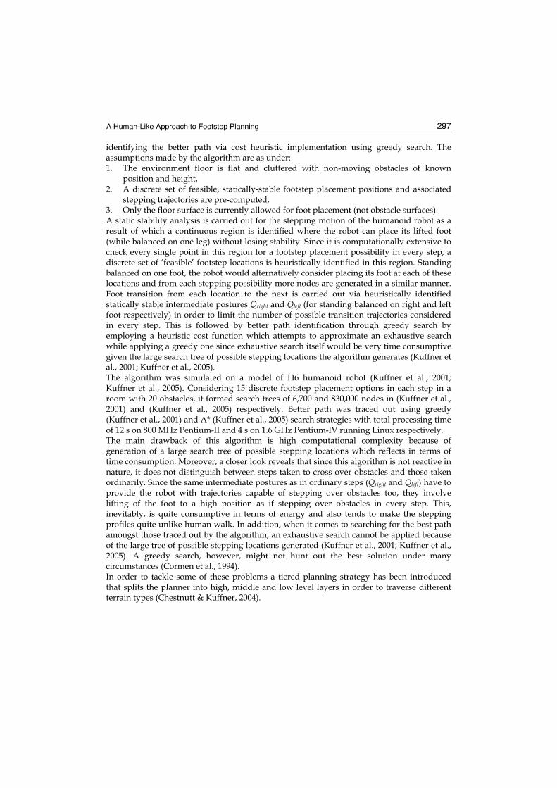
location to this circle around the destination point. The point at which this tangent reaches the circle is our required destination for the foot from which the tangent was dropped. The turning process begins with the robot first orienting its foot (about which it intends to turn) along the tangent dropped in this way. Following this, the weight of the robot is shifted to the now turned foot and the rest of the body is turned about this foot to bring the robot back to the double support phase with both feet parallel to each other and its orientation towards the required destination.
d
r
(x , y )f f
(x , y )d d
Figure 3. Turning towards a goal location
If the angle of turning is more than the angle of twist achievable by the robot’s leg in one step, the turning motion is split into two turnings. Also, apart from simple turning, we also use another turning motion attributed to as ‘Extended’ or ‘On-Walk’ turning in which the turning motion is coupled with the stepping motion (i.e. the robot does not place its foot down after twisting the leg only; instead, it twists the leg and then also extends it forwards to take a step before putting it down again and rotating the rest of the body about it to complete the turning motion). Coming to stepping trajectories for a normal step, any trajectory can be used with minimum foot-lift since no crossing over obstacles is intended (we use foot-lift of 0.05 m for Saika-3).
4.3 Stepping Over Obstacles
4.3.1 Enhancing the Stepping Area
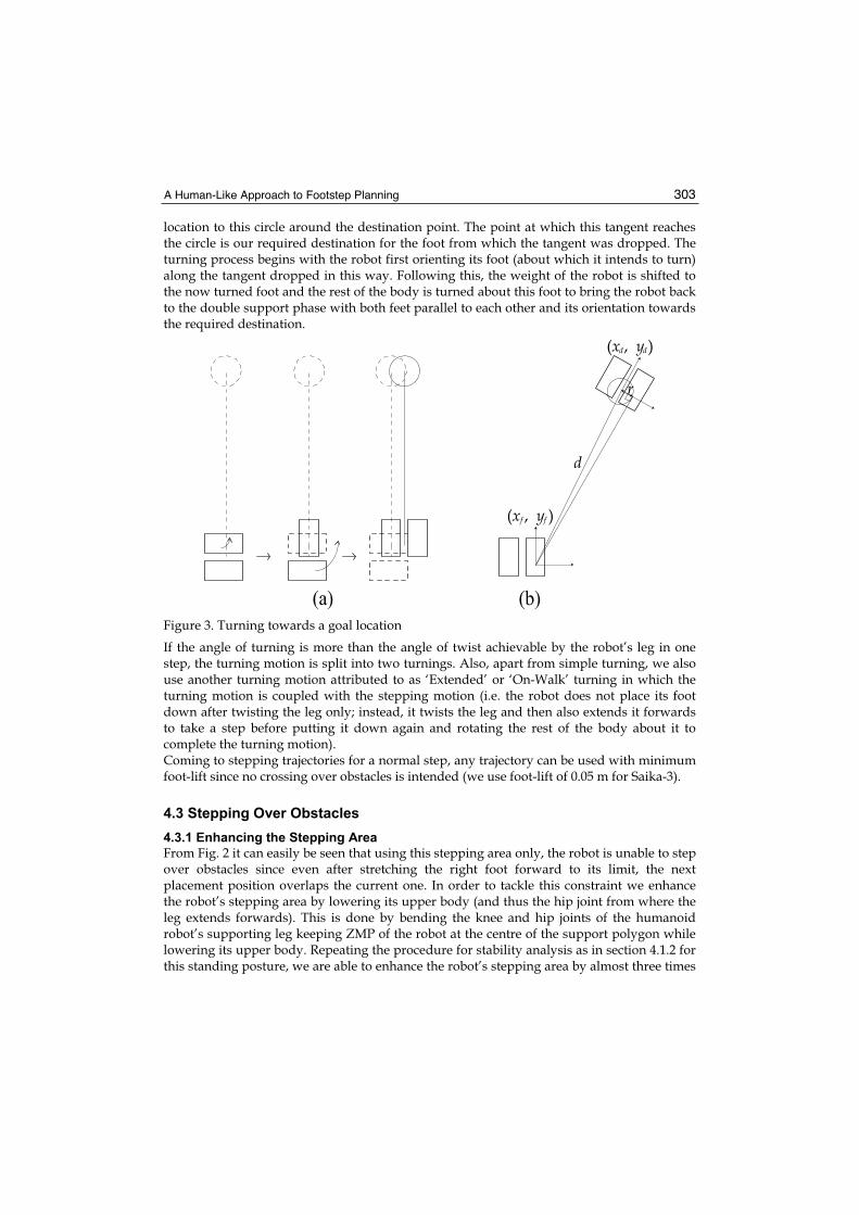
From Fig. 2 it can easily be seen that using this stepping area only, the robot is unable to step over obstacles since even after stretching the right foot forward to its limit, the next placement position overlaps the current one. In order to tackle this constraint we enhance the robot’s stepping area by lowering its upper body (and thus the hip joint from where the leg extends forwards). This is done by bending the knee and hip joints of the humanoid robot’s supporting leg keeping ZMP of the robot at the centre of the support polygon while lowering its upper body. Repeating the procedure for stability analysis as in section 4.1.2 for this standing posture, we are able to enhance the robot’s stepping area by almost three times

Humanoid Robots, Human-like Machines 304
(Fig. 4), thus providing a gap between current and next footstep placement locations (0.09 m for Saika-3). As obvious, enhanced stepping posture is more energy consuming, therefore, it is used only when crossing over obstacles.
0.0
9 m
Figure 4. Enhanced stable stepping area. Right foot is extended to its limit
4.3.2 Foot Trajectory
There exist strategies to compute optimum trajectory for the non-supporting foot while stepping over obstacles located perpendicular to the robot’s line of motion (Guan et al., 2005; Guan et al., 2006). However, conducting such analysis every time obstacles of different sizes are encountered from different angles would be computationally extensive (Kuffner et al., 2001). On the other hand, if in one step even if the foot is lifted to a height slightly more than minimally required to step over a certain obstacle, it would not amount to much additional energy consumption while making the computation significantly faster. The strategy we adopt, thus, is to fix a trajectory for stepping over obstacles as long as the obstacle satisfies certain dimensional constraints. The foot trajectory we use is shown in Fig. 5.We assign ankle joints the job of keeping the foot parallel to the ground at all times. Thus, the whole part of the leg below the ankle top remains pointed straight downwards during the stepping motion. Any obstacle with height below the ankle top (0.106 m in case of Saika-3) would thus, not cause a collision while stepping over using this enhanced stepping trajectory if it is small enough to fit into the gap between current and next footstep locations as traced out in the previous subsection. Thus for Saika-3, obstacles fitting within the 0.09 m

A Human-Like Approach to Footstep Planning 305
x 0.1 m dimensional constraint are marked as scalable by stepping over. A point to be noticed here is that the limitation of 0.1 m on the height of the scalable obstacle is there because of the simple strategy employed for stepping over. Surely, for future work, by using more sophisticated stepping over trajectories it is possible to relax this limit.
Obstacle0 0.05 0.1 0.15 0.2 0.25 0.3 0.35
0
0.02
0.04
0.06
0.08
0.1
0.12
0.14
0.16
0.18
0.2
Foot extension (xo)
Hei
ght
of
foot
from
gro
und (
along z o
)
Enhanced step (over obstacle)
Figure 5. Stepping over an obstacle
4.3.3 Tilted Obstacle
While traversing an obstacle cluttered terrain, the robot might approach obstacles placed at orientations other than directly perpendicular to its line of motion. In this case, where the foot trajectory becomes somewhat complex, the limit on the allowable width of the obstacle possible to be stepped over might be somewhat relaxed (however, we do not make use of this relaxation in our simulations currently). This is achieved by hovering one foot over the obstacle while stepping over instead of placing it down at the mean position (Fig. 6 (c)). As is evident from Fig. 6, the strategy is for the robot to stop and balance itself in double support state one step short of (i.e. at a distance of Length of one step +Length of Foot/2 before) reaching the point of intersection between the obstacle’s near side and the robot’s line of motion (Fig. 6 (a)). Next, if the obstacle’s tilt is rightwards compared with the direction of motion, the left foot of the robot is extended one step forward (Fig. 6 (b)) or vice versa. Balanced on this foot now, the robot lifts the right foot to a height of 0.12 m (as for the trajectory in Fig. 5) and then brings it to the mean position. At this point, the foot, while continuously lifted up from the ground, is turned to cross over the obstacle such that it is oriented perpendicular to the obstacle’s away side. Extending the foot forward using a similar trajectory as in Fig. 5, only now at the newly acquired orientation, brings the robot to the state shown by Fig. 6 (c). Balancing itself on the right foot now, the left foot is also lifted and then turned to the same orientation as the right, followed by achievement of double support state as shown in Fig. 6 (d) by moving the left foot over the obstacle as well to complete the stepping over process.

Humanoid Robots, Human-like Machines 306
(a) (b) (c) (d)
Figure 6. Stepping over an obstacle placed at an angle to the direction of motion. (a) Stopping one step short of the obstacle to achieve enhanced stepping posture. (b) Extending foot to balance on while stepping over based upon obstacle’s tilt. (c) Moving one foot over the obstacle. Dotted impression shows foot while lifted. (d) Moving other foot over the obstacle to complete stepping over.
5. Footstep Planning
Our algorithm inherits assumptions (i) and (iii) from the game theory based footstep planner described in section 2. The aim, as described in section 3, is to follow a human-like strategy for footstep planning moving from simpler to more complex paths while only considering those obstacles that necessarily hinder the robot’s way during graph expansion.
5.1 Obstacle Classification
In human environments, obstacles are of a variety of shapes and sizes. Our algorithm requires identification of a box-like boundary around each obstacle such that the obstacle of arbitrary shape is entirely contained inside it. This box-like boundary must be a four cornered shape when viewed from the top but there is no restriction on it being a rectangle or a parallelogram as long as it is a four cornered shape in top view. However, stepping over is only attempted in case the width and height of the boundary that binds the obstacle satisfy the constraints described in Section 4.3.2. Our algorithm at this stage considers the entire area inside this boundary in which the obstacle of arbitrary shape is contained as an obstacle. These obstacles are classified into three groups:
Type-1: Height 0.1 m
Type-2: 0.1 m < Height < 0.6 m
Type-3: Height 0.6 m
Can be crossed by stepping over if width 0.09 m.
Cannot be crossed by stepping over but while dodging it if the foot does not strike it, nothing else will either.
Cannot be crossed by stepping over and while dodging we have to make sure the robot’s arms (which stick out wider than its feet) do not collide with it. The 0.6 m height is the distance of the ground surface from the lowest point of Saika-3’s arms. This distance will obviously vary from one humanoid robot to another.
A Human-Like Approach to Footstep Planning 307
5.2 Collision Detection
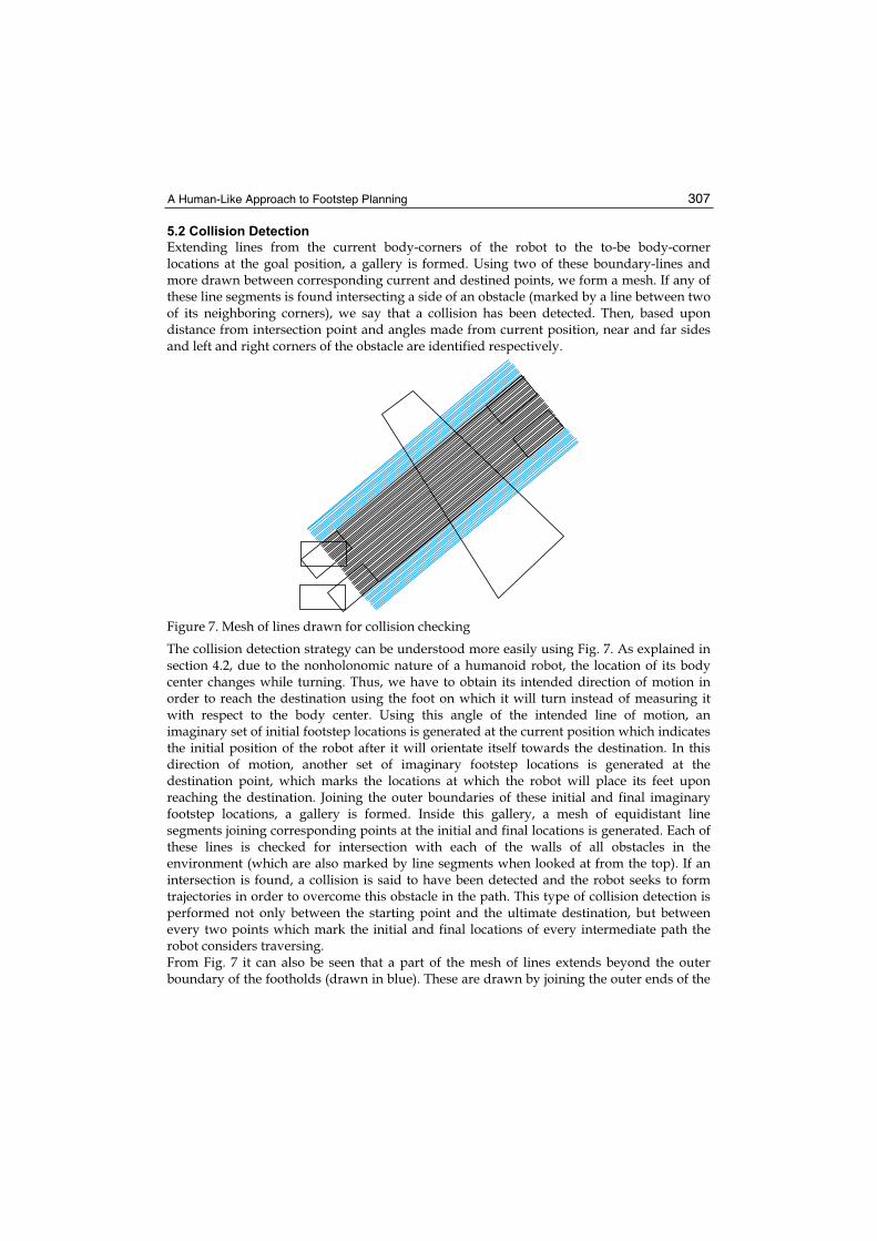
Extending lines from the current body-corners of the robot to the to-be body-corner locations at the goal position, a gallery is formed. Using two of these boundary-lines and more drawn between corresponding current and destined points, we form a mesh. If any of these line segments is found intersecting a side of an obstacle (marked by a line between two of its neighboring corners), we say that a collision has been detected. Then, based upon distance from intersection point and angles made from current position, near and far sides and left and right corners of the obstacle are identified respectively.
Figure 7. Mesh of lines drawn for collision checking
The collision detection strategy can be understood more easily using Fig. 7. As explained in section 4.2, due to the nonholonomic nature of a humanoid robot, the location of its body center changes while turning. Thus, we have to obtain its intended direction of motion in order to reach the destination using the foot on which it will turn instead of measuring it with respect to the body center. Using this angle of the intended line of motion, an imaginary set of initial footstep locations is generated at the current position which indicates the initial position of the robot after it will orientate itself towards the destination. In this direction of motion, another set of imaginary footstep locations is generated at the destination point, which marks the locations at which the robot will place its feet upon reaching the destination. Joining the outer boundaries of these initial and final imaginary footstep locations, a gallery is formed. Inside this gallery, a mesh of equidistant line segments joining corresponding points at the initial and final locations is generated. Each of these lines is checked for intersection with each of the walls of all obstacles in the environment (which are also marked by line segments when looked at from the top). If an intersection is found, a collision is said to have been detected and the robot seeks to form trajectories in order to overcome this obstacle in the path. This type of collision detection is performed not only between the starting point and the ultimate destination, but between every two points which mark the initial and final locations of every intermediate path the robot considers traversing. From Fig. 7 it can also be seen that a part of the mesh of lines extends beyond the outer boundary of the footholds (drawn in blue). These are drawn by joining the outer ends of the

Humanoid Robots, Human-like Machines 308
arms of the robot (which stick out wider than its feet) at initial and goal locations. Only if an obstacle of type-3 is found to be colliding with a line in this outer part of the mesh (between the feet and the arms), a collision is said to have been detected. With respect to collision detection, two kinds of simulation results are presented in this chapter. In one, the mesh comprises only 3 lines (two joining body ends and one joining body center at initial and goal locations). In the other, we form a mesh of 27 lines with a distance of less than 2 cm between every two neighboring line segments.
5.3 Overcoming an Obstacle
To dodge an obstacle from a side we choose pivot points near the obstacle corners as shown in Fig. 8.
dd
dd
Figure 8. Choosing pivots to dodge an obstacle from right
The distance ‘d’ along the extended side is chosen such that no part of the robot’s body collides with the obstacle as the robot stands in double support phase with its body centre at the pivot point. For instance in case of type-1 and type-2 obstacles, this distance is equal to half the length of the diagonal of the rectangular support polygon formed when the robot stands in the double support phase. This is because the outer most edges of the feet are the points closest to the obstacle with which there might be a chance of collision. ‘d’ can thus be different for each obstacle type but not for obstacles of one group. It is obviously greater for obstacles of type-3 since there is a possibility of collision with the robot’s upper body. As explained in section 4.3, to step over an obstacle, the robot balances itself on both legs one step short of the closest step-location near the obstacle. Next, based on rightward or leftward tilt of the obstacle in relevance with the robot’s trajectory, it places forward left or right foot respectively and balances itself on it. Using enhanced stepping motion, the robot now takes a step forward with its movable leg, making sure that the extended foot lands with its back-side parallel to the obstacle’s away-side. Fig. 9 displays the trajectories taken to overcome an obstacle of type-1.

A Human-Like Approach to Footstep Planning 309
Figure 9. Overcoming an obstacle of type-1
5.4 Local Loops and Deadlocks
Each obstacle in the surroundings is allotted an identification number. The planner keeps a history of the obstacles it has overcome in a path as it plans footsteps. Whenever an obstacle occurs twice, it indicates a local loop or deadlock since attempting to overcome it again is bound to bring the planner back to the same position again and again. Such a trajectory is immediately abandoned and pruned from the search tree.
Figure 10. Avoiding local loops and deadlocks while crossing obstacle ’1’ of type-1

Humanoid Robots, Human-like Machines 310
One such situation where the robot encounters a local loop and deadlocks while trying to dodge the obstacle labelled ‘1’ from both right and left sides is shown in Fig. 10. For instance, when trying to dodge the obstacle labelled ‘1’ in Fig. 10 from the right, the robot chooses pivot points to pass from its right side as elaborated upon in section 5.3. However, this path is obstructed by another obstacle on the robot’s right. To dodge this newly encountered obstacle, once again the robot forms trajectories from its right and left. The one attempted to pass from left finds the obstacle labelled ‘1’ in the way again. Since this obstacle is present in the history as one that has already been attempted to be dodged, the trajectory for dodging the newly encountered obstacle from the left is discarded as a situation where a deadlock is encountered. The trajectory formed to dodge it from the right, however, finds another obstacle (indicated as a type-3 obstacle in Fig. 10). Attempting to dodge this type-3 obstacle from the left results in a deadlock just as in the previous case whereas the one attempted from its right encounters yet another obstacle. This process is repeated twice more until, in an effort to dodge from the right the obstacle to the left of the obstacle labelled ‘1’, the obstacle labelled ‘1’ is encountered again. This trajectory, therefore, is also abandoned and a local loop is said to have been encountered. A similar situation occurs while trying to dodge the obstacle labelled ‘1’ in Fig. 10 from its left side. Thus the only trajectory possible to overcome this obstacle which is free of local loops and deadlocks is the one formed by stepping over. As we can see, the planner only plans the successful trajectory, avoiding getting stuck in local loops and deadlocks.
5.5 Cost Assignment
A heuristic cost based on the order of complexity of each stepping motion is given at Table 1. These costs are assigned to foot placements of each type as they are planned.
Step type Cost
Straight 1
Turning 2
Extended 3
Enhanced 4
Table 1. Heuristic costs assigned to steps of different types
5.6 Intermediate Paths
If, in order to proceed towards a pivot point while dodging an obstacle from its side, another obstacle is encountered along the way, alternate paths based upon the obstacle type are formed. All these alternate paths converge at the pivot point, meaning that they will all have similar descendants. Thus, the number of these intermediate alternate paths is multiplied by the number of descendent paths and added to the total number of possible alternate paths. Thus, evaluating cost of each intermediate path and keeping only the best during alternate path creation reduces the number of paths to only useful ones.
5.7 Search for Best Path
In order to identify the best one of the paths formed by our algorithm, we employ a depth first exhaustive search since greedy or A* search would not filter out for us the best path in every scenario (Cormen, 1994).

A Human-Like Approach to Footstep Planning 311
6. Results
Figure 11. Various paths for reaching the destination in an obstacle cluttered environment
Figure 12. Best path determined using depth first exhaustive search

Humanoid Robots, Human-like Machines 312
Figs. 11 and 12 show results of a simulation of Saika-3 planning footsteps in a room with 20 obstacles. We see that a graph of only 1,529 nodes is formed consisting of 54 paths all reaching the destination. The whole process takes only 437 ms using a mesh of 3 lines (for collision detection) and 864 ms using a mesh of 27 lines on a 1.86 GHz Pentium-IV Centrino (1.5 GB RAM) running Windows XP. A comparison with previous techniques reviewed in section 2 shows reduction in the number of nodes as well as in processing time even though the algorithm employs exhaustive search for hunting out best path which guarantees optimality of the chosen path among those traced out by the algorithm. Some more simulation results are given in Figs. 13-15. We see that the fastest result with the extensive collision checking strategy (27 line mesh) is obtained in Fig. 15. The reason for this is the very small branching that has taken place in the graph. This also reduces the time taken in search for best path. Also, Fig. 14 shows the trajectories formed around the obstacle of type-3 (hatched). It is readily observed that the robot keeps a greater distance with this obstacle than with obstacles of other types.
(a) Alternate paths (b) Best path
Figure 13. Result 2: Nodes formed 752, paths 28, time taken 234 ms (3 line mesh)
(a) Alternate paths (b) Best path
Figure 14. Result 3: Nodes formed 582, paths 17, time taken 688 ms (27 line mesh)

A Human-Like Approach to Footstep Planning 313
(a) Alternate paths (b) Best path
Figure 15. Result 4: Nodes formed 401, paths 8, time taken 422 ms (27 line mesh)
7. Conclusion
Our algorithm successfully demonstrates a novel global reactive footstep planning strategy with a human-like approach. Incremental graph expansion from simpler to more complex paths ensures formation of a simpler and more useful graph as compared to that formed by approaches such as the visibility graph. The trajectory generated is more energy-efficient since the robot does not have to lift its foot to a high location in every step as in case of game theory based approaches. The algorithm is considerably fast and reduces computational complexity by minimizing the number of alternate steps considered after planning each step. However, basing the cost of each step on energy or time optimisation criteria instead of just the complexity level of the stepping motion can further improve the performance of the algorithm. Possibilities for future work include implementation on real humanoid robot and incorporation of measures for dealing with dynamic obstacles in the environment. In addition, identification of alternate paths by considering postural changes also seems interesting e.g. constraints on many obstacles of type-3 can be reduced to those for type-2 if the robot only lifts up its arms.
8. References
Ayaz, Y.; Afzal, B.; Saeed, M. & Rehman, S.U. (2004). Design, Fabrication and Control of a Two-Legged Walking Robot, Proceedings of IEEE Int. Workshop. on Robot Motion & Control (RoMoCo), pp. 73-78
Ayaz, Y.; Munawar, K.; Malik, M.B. ; Konno, A. & Uchiyama, M. (2006). Human-Like Approach to Footstep Planning Among Obstacles for Humanoid Robots, Proc. ofIEEE/RSJ Int. Conf. on Intelligent Robots and Systems (IROS), pp. 5490-5495
Chestnutt, J. & Kuffner, J.J. (2004). A Tiered Planning Strategy for Biped Navigation, Proceedings of IEEE Int. Conf. on Humanoid Robotics (ICHR)
Chestnutt, J.; Lau, M.; Cheung, G.; Kuffner, J.J.; Hodgins, J. & Kanade, T. (2005). Footstep Planning for the Honda Asimo Humanoid, Proceedings of IEEE Int. Conf. on Robotics & Automation (ICRA), pp. 629-634
Cormen, T.H.; Leiserson, C.E. & Rivest, R.L. (1994). Introduction to Algorithms, McGraw-Hill Book Company

Humanoid Robots, Human-like Machines 314
Guan, Y.; Neo, E.S.; Yokoi, K. & Tanie, K. (2005). Motion Planning for Humanoid Robots Stepping over Obstacles, Proceedings of IEEE/RSJ Int. Conf. on Intelligent Robots and Systems (IROS), pp. 364-370
Guan, Y.; Neo, E.S.; Yokoi, K. & Tanie, K. (2006). Stepping Over Obstacles With Humanoid Robots. IEEE Trans. on Robotics, Vol. 22, No. 5, pp. 958-973
Konno, A.; Kato, N.; Shirata, S.; Furuta, T. & Uchiyama, M. (2000). Development of a Light-Weight Biped Humanoid Robot, Proceedings of IEEE/RSJ Int. Conf. on Intelligent Robots and Systems (IROS), pp. 1565-1570
Kuffner, J.J.; Nishiwaki, K.; Kagami, S.; Inaba, M. & Inoue, H. (2001). Footstep Planning Among Obstacles for Biped Robots, Proceedings of IEEE/RSJ Int. Conf. on Intelligent Robots and Systems (IROS), pp. 500-505
Kuffner, J.J.; Nishiwaki, K.; Kagami, S.; Inaba, M. & Inoue, H. (2003). Online Footstep Planning for Humanoid Robots, Proceedings of IEEE/RSJ Int. Conf. on Robotics and Automation (ICRA), pp. 932-937
Kuffner, J.J.; Nishiwaki, K.; Kagami, S.; Inaba, M. & Inoue, H. (2005). Motion Planning for Humanoid Robots. Robotics Research, Paolo Dario and Raja Chatila (Eds.), Springer Tracts in Advanced Robotics, Vol.15, pp. 365-374
Latombe, J.C. (1991). Robot Motion Planning, Kluwer Academic Publishers, Boston, MA McGhee, R.B. & Iswandhi, G.I. (1979). Adaptive Locomotion of a Multi-legged Robot over
Rough Terrain. IEEE Trans. on Systems, Man and Cybernetics, Vol. SMC-9, No. 4, pp. 176-182
Michel, P.; Chestnutt, J.; Kuffner, J.J. & Kanade, T. (2005). Vision-Guided Humanoid Footstep Planning for Dynamic Environments, Proceedings of IEEE/RAS Int. Conf. on Humanoid Robotics (ICHR), pp. 13-18
Michel, P.; Chestnutt, J.; Kagami, S.; Nishiwaki, K.; Kuffner, J.J. & Kanade, T. (2006). Online Environment Reconstruction for Biped Navigation, Proceedings of IEEE Int. Conf. on Robotics & Automation (ICRA), pp. 3089-3094
Vukobratovi , M. & Borovac, B. (2004). Zero Moment Point---35 Years of Its Life. International Journal of Humanoid Robotics, World Scientific Publishing Company, Vol. 1, No. 1, pp. 157-173
Yagi, M. & Lumelsky, V. (1999). Biped Robot Locomotion in Scenes with Unknown Obstacles, Proceedings of IEEE Int. Conf. on Robotics & Automation (ICRA), pp. 375-380

Humanoid Robots, Human-like MachinesEdited by Matthias Hackel
ISBN 978-3-902613-07-3Hard cover, 642 pagesPublisher I-Tech Education and PublishingPublished online 01, June, 2007Published in print edition June, 2007
InTech EuropeUniversity Campus STeP Ri Slavka Krautzeka 83/A 51000 Rijeka, Croatia Phone: +385 (51) 770 447 Fax: +385 (51) 686 166www.intechopen.com
InTech ChinaUnit 405, Office Block, Hotel Equatorial Shanghai No.65, Yan An Road (West), Shanghai, 200040, China
Phone: +86-21-62489820 Fax: +86-21-62489821
In this book the variety of humanoid robotic research can be obtained. This book is divided in four parts:Hardware Development: Components and Systems, Biped Motion: Walking, Running and Self-orientation,Sensing the Environment: Acquisition, Data Processing and Control and Mind Organisation: Learning andInteraction. The first part of the book deals with remarkable hardware developments, whereby completehumanoid robotic systems are as well described as partial solutions. In the second part diverse results aroundthe biped motion of humanoid robots are presented. The autonomous, efficient and adaptive two-leggedwalking is one of the main challenge in humanoid robotics. The two-legged walking will enable humanoidrobots to enter our environment without rearrangement. Developments in the field of visual sensors, dataacquisition, processing and control are to be observed in third part of the book. In the fourth part some "mindbuilding" and communication technologies are presented.
How to referenceIn order to correctly reference this scholarly work, feel free to copy and paste the following:
Yasar Ayaz, Khalid Munawar, Mohammad Bilal Malik, Atsushi Konno and Masaru Uchiyama (2007). A Human-Like Approach to Footstep Planning, Humanoid Robots, Human-like Machines, Matthias Hackel (Ed.), ISBN:978-3-902613-07-3, InTech, Available from:http://www.intechopen.com/books/humanoid_robots_human_like_machines/a_human-like_approach_to_footstep_planning

© 2007 The Author(s). Licensee IntechOpen. This chapter is distributed under the terms of theCreative Commons Attribution-NonCommercial-ShareAlike-3.0 License, which permits use,distribution and reproduction for non-commercial purposes, provided the original is properly citedand derivative works building on this content are distributed under the same license.