a hybrid communications network approach for … alcatel mdr and aviat (harris) microwave equipment...
TRANSCRIPT

Place your chosen image here. The four corners must just cover the arrow tips. For covers, the three pictures should be the same size and in a straight line.
2017 CIGRE Grid of the Future SymposiumJohn-Paul H. Knauss, PE
A Hybrid Communications Network Approach for Advanced Applications on the Modern Grid

2
Private Telecom Network
Key Stats Private Network
Fiber Route Miles……... 1311T-1 Circuits …….…….….400Protection ……………….250Radio Circuits ………….350EMS Circuits …………500Voice Circuits …………400Total Circuits ….. ..…… 1,900
Radio Sites ……………. 81Comm Rooms ………… 74Alarm Status Systems ……125Batteries & Chargers………125
NE & Upstate NY Leased CircuitsT-1's ………. 500EMS……. 1473GEMS ……. 243Radio………. 124Other……. 1311Total Lines…... 3651
% BW Leased vs Private = 53% (approximate)

3
Private Telecom Network
More than 1300 route miles of backbone fiber
Most backbone fiber is either wholly owned by National Grid or by others with National Grid having Indefeasible Right to Use (IRU)
Optical transport is SONET platform with DWDM on backbone
Legacy Equipment Alcatel Lucent DMX Platform with some DDM-2000 Approximately 141 optical nodes deployed, mostly at transmission substations and Control Centers GE JMUX in substations for protective relay applications RFL IMUX in substations for protective relay applications Digital cross connect systems Tellabs 532 (1/0)
Microwave Sites Approximately 81 radio tower sites Mostly Alcatel MDR and Aviat (Harris) microwave equipment deployed Microwave radios use TDM platform at 155Mbs or 45Mbs

4
Microwave / Radio Tower Sites

5
Electric Substations

6
Typical Transmission Substation
SONET Ring
All fiber routes separated by 3 feet minimum
Control Center
National Grid Fiber
SONET Optical Transport
SUBSTATION B
Protective Relay A-B
Protective Relay A-B
Protective Relay B-A
Protective Relay B-A
Primary SCADA
Backup SCADA
Backup Control Center
SUBSTATION A
Protective Relay A-C
SUBSTATION C
Protective Relay C-A
POTS
POTS
POTS
7
Transmission Substation Communications
Physical Security AMAG card readers and access control system Video cameras
Monitoring and Control: Energy Managements System (EMS) - EMS RTU data & Wide Are Network (WAN) Metering – Wired and Wireless for Power Control Gas Energy Managements System (GEMS) – RTU and Wide Are Network (WAN) Digital Fault Recorders (DFR’s) for event analysis
System Protection: Bulk power system protection per NPCC Criteria
Dispatch Radio Radio communications from Dispatch and Control Centers to field operations mobile radio
Telephone Talk lines for NPCC Black Start Procedures E911

8
Distribution & Sub-Transmission Legacy Communications Historically, National Grid has remotely monitored and controlled thousands of intelligent devices on
their distribution, sub-transmission, and transmission systems through a combination of both private networks as well as cellular communications platforms that were provided in a hosted, Software as a Service (SaaS), environment.
Annual SaaS cost was ~ $400,000 for communication with 1732 reclosers at 70kb/device/month. Analog updates once a week. Binary updates twice a day statically, with unsolicited report-by-exception.
SaaS offerings provided to National Grid:
Cellular communications
AT&T 2G & 3G network, monitoring and maintenance
Web portal
Visibility to the recloser data, event based actions, group notifications and commissioning aid.
DNP Server
SCADA interface.
The AT&T 2G service was sunset at the end of 2016.
To maintain communications beyond 2016, all 1732 recloser locations required a site visit to upgrade the hardware.
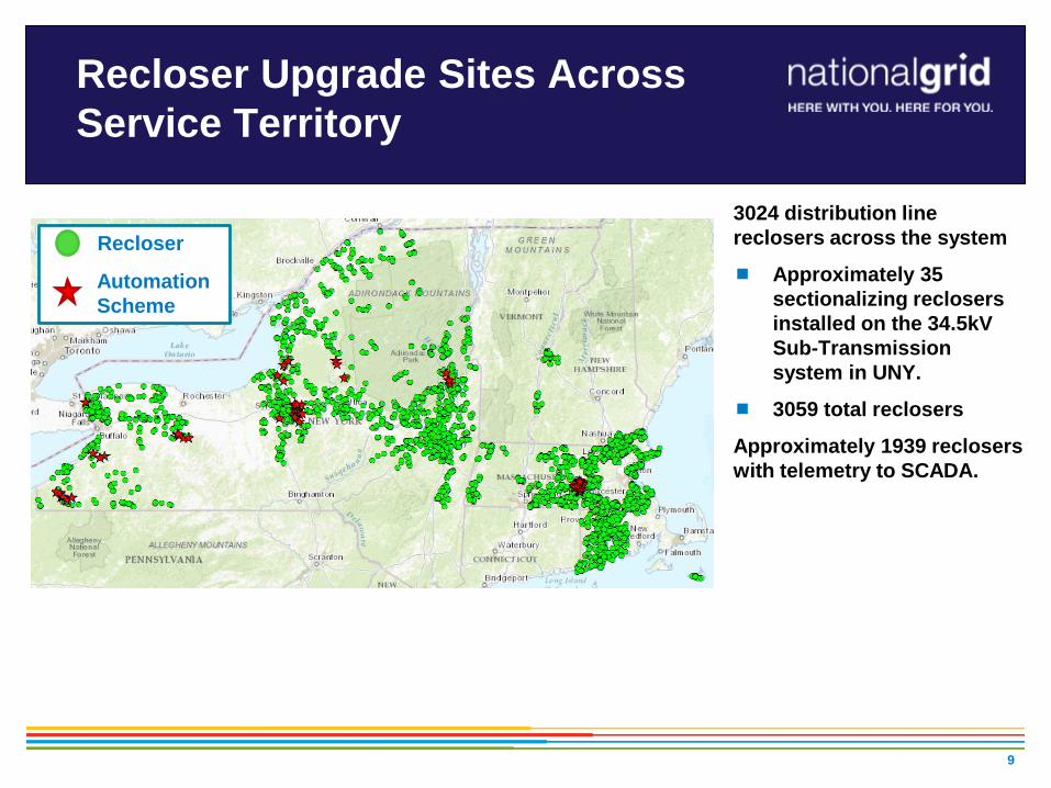
Recloser Upgrade Sites Across Service Territory
9
Recloser
AutomationScheme
3024 distribution line reclosers across the system
Approximately 35 sectionalizing reclosers installed on the 34.5kV Sub-Transmission system in UNY.
3059 total reclosers
Approximately 1939 reclosers with telemetry to SCADA.

10
New Hybrid Communication Network Architecture
Experience gained through “Smart Grid”, Volt / VAr Optimization (VVO), and new technology demonstration pilots, illustrated that the future of communications technologies deployed across the system would require a flexible model.
From a functionality perspective, there is a need to support various types of communications technologies as application requirements can vary greatly, and dictate acceptable solutions.
With a varying service territory inclusive of existing pockets of private RF infrastructure, as well as remote locations where further network buildout can be difficult to justify, the concept of a hybrid connectivity model became critical for sustainability.
Modern network architectures for system critical operations require low-latency, a high degree of availability, reliability, serviceability, security, and redundancy with varied degrees of cost and complexity.

Private IP Network Overview
11
Layer 3 MPLS virtual private network solution facilitates secure connectivity to multiple hub locations, enabling system redundancy, and failover capability.
12
High-Level MPLS VRF Topology
A network architecture was developed that would allow data from field devices to integrate to both primary back-office systems (e.g., data concentrators, SCADA, management portal, etc.) as well as secondary (backup) facilities should they be warranted.
Cyber security was a primary focus during the entire network design and was embedded from inception to implementation, complete with PEN testing and validation.
New virtual routing and forwarding (VRF) solutions were identified to establish desired connectivity to all required facilities, including both primary and backup System Control Centers, and Data Centers

High-Level MPLS VRF Topology
13
New VRF for Access from VSTIGs to Site #1
and Site #2 for New York Reclosers Only
VSTIGS #2VSTIGS #1Primary Path
High Level MPLS VRF Topology
Site #2
New VRF for Access from VSTIGs to Site #2
and Site #3 for New England Reclosers Only
New VRF for New York VzW Access
Site #1
National GridCNI
Each VzW VRF will have a Separate IP Address Pool
New VRF for New England VzW Access
Secondary Path
Site #3
Existing VRF Existing VRF
Data Center

Single Facility Physical Technology Model Example
14
New LAN Switch
Verizon MPLS Network
2 NEW VRFs (New for NY Reclosers)2 NEW VRFs (New for NE Reclosers)
New England Recloser
Server x 12
CNI firewall
CNINetwork
Note:Connections to the CNI network does not show all details due to security concerns.
Router #2Router #1
QA Firewall Production Firewall
Supported by National Grid
Supported by Verizon NOC
2 Port Ether-channel
IP Address Pool Size30 IP address for Grid
Device Servers
Loopback
Interface Gi 0/0/31 - VLAN A – 0.0.0.0 /271 - VLAN B – 0.0.0.0 /272 - VLAN C – 0.0.0.0 /273 - VLAN D – 0.0.0.0 /274 - VLAN E – 0.0.0.0 /265 - VLAN F – 0.0.0.0 /265 - VLAN G – 0.0.0.0 /26
CE Router HSRP1 - VLAN A – 0.0.0.0 /271 - VLAN B – 0.0.0.0 /272 - VLAN C – 0.0.0.0 /273 - VLAN D – 0.0.0.0 /274 - VLAN E – 0.0.0.0 /265 - VLAN F – 0.0.0.0 /265 - VLAN G – 0.0.0.0 /26
Loopback
Interface Gi 0/0/31 - VLAN A – 0.0.0.0 /271 - VLAN B – 0.0.0.0 /272 - VLAN C – 0.0.0.0 /273 - VLAN D – 0.0.0.0 /274 - VLAN E – 0.0.0.0 /265 - VLAN F – 0.0.0.0 /265 - VLAN G – 0.0.0.0 /26
New Switch (Managed by National Grid)
New Switch (Managed by National Grid)

Device Connectivity Example
15

Device Connectivity
Given the varying nature of both legacy and modern control equipment deployed across the service territory, both serial and Ethernet connectivity was required.
In most cases, Verizon 4G / LTE Cellular based multi-service connected routers were used to replace the legacy cellular based modems.
The router’s port forwarding functionality, on-board terminal server, and firewall, was leveraged to simultaneously accommodate both serial and Ethernet communications in a single, secure, package.
This approach results in a truly “plug and play”, IP addressable, solution for any device on the network.
These new edge routers communicate through the Verizon Cloud (routed via MPLS) to National Grid owned RTUs / data concentrators located at System Control Centers.
Currently integrating satellite links to the wireless gateways / PIP network for additional flexibility.
Pilot demonstrations have taken place and currently integrating Enterprise solutions.
The PI Data Historian system is being used to archive operational data for analytics.
16
Private RF Network Integration
Worcester Smart Energy Solutions Demonstration ~200 “Grid” Devices on 3.65GHz. Point-to-Multipoint Private WiMAX Network
~15,000 electric meters on Private 900MHz. mesh network / cellular backhaul
RI VVO Trilliant Private 5.8GHz. Radio System - ~35 devices
4RF Private Licensed 900MHz. Point-to-Multipoint Radio Areas in MECO / NECO regions
Upgrades to older GE MAS systems w/ ~60 remote units
New IP based 4RF units currently considered where network availability is reasonable to achieve
4RF Private Licensed 700 MHz. Point-to-Multipoint Radio System Nantucket Island
GE MDS Private (Unlicensed) 900MHz. Point-to-Multipoint Radio System Western New York, ~ 200 Devices
Upstate NY DA Schemes with Private Point-to-Point 900MHz. Radio Systems UtiliNET Radios
S&C SpeedNet Radios
17
Implementation Challenges
Strict risk management policies resulted in extensive time required to implement and test individual network changes. 90+ required network changes Each network ‘change’ was implemented individually and required a
subsequent 48hr window for testing and validation. Development of new processes was required to ensure a fluid deployment and
cutover to the new system. Training and Documentation
New technology (i.e., hardware) required training for all impacted Engineering and Operations personnel.
New processes rolled out to all impacted stakeholders. Extensive reference documentation required for sustainability.
18

Functional Network Benefits
Remote management of field devices through a secure Corporate portal: Device configuration Device security Remote Record Retrieval 2-way file transfer (remote firmware, settings, etc.)
Network and security management embedded in the design of the network architecture allowing for real-time monitoring and proactive action should anomalies be detected or when general maintenance is required (e.g., Syslog, SNMP, etc.)
19
FUNCTIONALITY
SCADA Near Real-Time Data
RemoteRecord
Retrieval
Remote Configuration
Remote DeviceTroubleshooting
Advanced Applications
Support
Data Historian
Legacy Telemetry Solution YES NO NO NO NO NO LIMITEDNew Network Architecture YES YES YES YES YES YES YES
