a hydrogel-actuated environmentally-sensitive microvalve
TRANSCRIPT
1
Submitted to the Journal of Microelectromechanical Systems A HYDROGEL-ACTUATED ENVIRONMENTALLY-SENSITIVE MICROVALVE FOR
ACTIVE FLOW CONTROL
Antonio Baldi 1, Yuandong Gu 2, Paul E. Loftness 3, Ronald A. Siegel 2,4, Babak Ziaie 1,4
1Department of Electrical and Computer Engineering 2Department of Pharmaceutics
3Department of Mechanical Engineering 4Department of Biomedical Engineering,
University of Minnesota
Minneapolis, MN 55455
Corresponding author: Antonio Baldi, 4-174 EE/CSci Bldg, 200 Union Street S.E., Minneapolis, MN
55455, USA, Ph: 612-626-7216, Fax: 612-625-4583, E-mail: [email protected].
ABSTRACT
This paper reports on the fabrication and test of a hydrogel-actuated microvalve that responds to
changes in the concentration of specific chemical species in an external liquid environment. The
microvalve consists of a thin hydrogel, sandwiched between a stiff porous membrane and a flexible
silicone rubber diaphragm. Swelling and deswelling of the hydrogel, which results from the diffusion of
chemical species through the porous membrane is accompanied by the deflection of the diaphragm and
hence closure and opening of the valve intake orifice. A phenylboronic acid based hydrogel was used to
construct a smart microvalve that responds to the changes in the glucose and pH concentrations. The
fastest response time (for a pH concentration cycle) achieved was 7 minutes using a 30 µm thick hydrogel
and a 60 µm thick porous membrane with 0.1 µm pore size and 40% porosity.
Index terms : Microvalve, Microfluidics, Hydrogel, Smart Material, Drug Delivery.
brought to you by COREView metadata, citation and similar papers at core.ac.uk
provided by Digital.CSIC
2
I. INTRODUCTION
Environmentally sensitive hydrogels offer unique opportunities for active flow control in microfluidic
systems. These tangled networks of cross-linked polymer chains, immersed in a solvent, manifest a
reversible and abrupt swelling and deswelling phase transition in response to the changes in
environmental factors such as glucose concentration, pH, electric field, temperature, and light [1-4]. This
transition often results in an abrupt volume change (swelling or shrinking) that can be as large as 1000
fold. Because of this property, hydrogels are attractive candidates as components of microactuators
operating in aqueous media such as body fluids. For example, the volume phase transition in these
materials can be harnessed in smart microfluidic components such as valves [5]. Transient swelling-
deswelling behavior of a chemically sensitive hydrogel is limited by the diffusion of chemical species into
the hydrogel and by the absorption and expulsion of the solvent (usually water). This results in
exceedingly long response times in situations where the diffusion path-length is large. However, in
certain microscale applications, the path-lengths become short enough to permit the hydrogels to be used
as mechanical actuators with a reasonable response time. Integrating hydrogels with MEMS microfluidic
structures such as valves and pumps therefore can provide smart microsystems that respond to various
environmental stimuli. Several different approaches have been proposed to accomplish this goal.
Hydrogels have been selectively photopolymerized around posts inside silicone microchannels to regulate
flow in response to the changes in the flowing solution [6]. Alternatively, hydrogels have been
polymerized as a pair of bistrip flaps attached to the walls of a microchannel forming a structure
mimicking venous valves [7]. Flow inside a microchannel has also been controlled by the concentration
of the solution flowing in an adjacent microchannel [6]. In this case the channels were separated by a
silicone rubber membrane, whose deflection by volume changes of the hydrogel placed in one channel
produced the opening and closing of an inlet hole in the other channel.
All the aforementioned techniques control the flow in response to the changes in the concentration of
a solution inside a microchannel. A recent design intended for drug delivery applications provides
3
external exposure of the hydrogel through a perforated plate [8]. However, in this device, the hydrogel is
manually loaded and the dimensions of the hydrogel cavity (macromachined from methacrylate plates)
are large and hence the response time is exceedingly slow (~10 hours response time). In this paper, we
describe the fabrication and test of a MEMS-based microvalve capable of responding in a reasonable time
(a few minutes, which is adequate for most drug delivery applications) to the changes in the concentration
of specific chemical species in an external liquid environment. In our approach, a thin hydrogel is
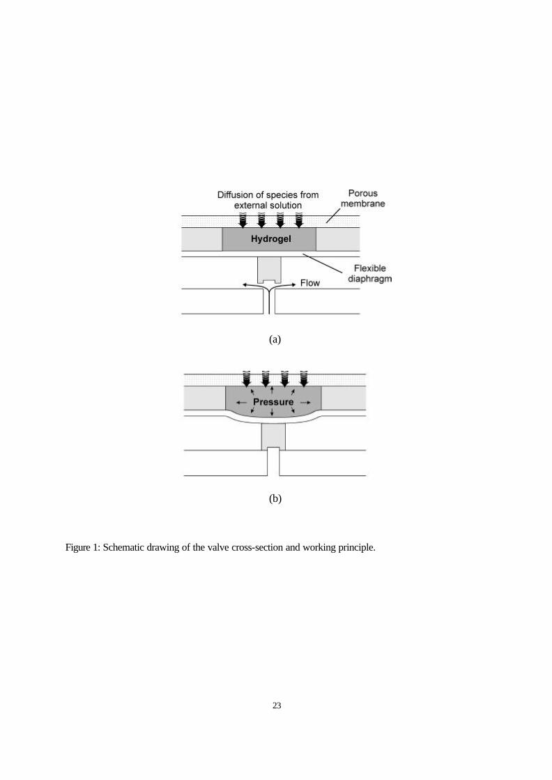
confined in a cavity that communicates with the external solution by diffusion through a stiff porous
membrane, Figure 1. The hydrogel’s volume change produces deflection of a bossed diaphragm that
opens and closes the intake orifice of the valve. We will demonstrate that by appropriate design of the
hydrogel-containing cavity and the porous membrane (i.e., its porosity, thickness, and pore size) it is
possible to achieve a response time of a few minutes. Applications of this unique approach are obvious in
the field of drug delivery microsystems and biotechnology. For example, variants of the present design
may prove useful for closed-loop delivery of insulin in response to fluctuations in blood glucose level
seen in diabetes. In subsequent sections, we will describe the design (Section II), fabrication (Section III),
hydrogel loading (Section IV), and test (Section V) of the glucose/pH-sensitive microvalve.
Some of the results reported in this paper were previously presented at MEMS 2002 and MMB 2002
conferences [9, 10].
II. HYDROGEL-ACTUATED MICROVALVE DESIGN
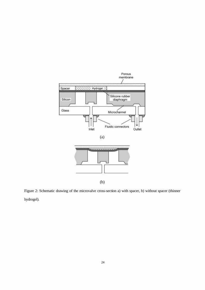
In this section we outline important design features of the microvalve. Figure 2-a shows the cross-
sectional schematic of the designed device. The main body of the microvalve is made out of silicon and
contains the bossed flexible diaphragm. A glass plate with inlet and outlet orifices and the porous
membrane are attached on either side of the silicon part to complete the valve structure. In the open
position (i. e. the hydrogel is shrunken), the liquid enters the inlet and passes through a microchannel
defined in the silicon, which fixes the flow rate (or dose rate), before leaving through the outlet. Specific
4
changes in the chemical environment generate a positive osmotic pressure leading to increased volume of
the hydrogel and subsequent deflection of the flexible diaphragm. As the hydrogel swells, the osmotic
pressure is partially relaxed and is also opposed by the elasticity of its polymeric network, the stress in the
deflected diaphragm, and the hydraulic pressure in the flow channel. When the boss contacts the glass
plate, the hydrogel cannot expand any more and the remaining osmotic pressure assures the closure of the
valve. In order to fully utilize the generated osmotic pressure, the diaphragm should oppose the hydrogel
expansion with a minimum possible force. In the present design a two-component silicone rubber (Nusil
MED10-6640) with a Young’s modulus of 1.18 MPa was used to fabricate the diaphragm. This product
was chosen because of its high tear resistance (42 kN/m) and low pre-polymer solution viscosity
necessary to obtain thin layers. With a thickness of 20 µm, a diameter of 1800 µm and a central boss
diameter of 500 µm, the diaphragm is expected to provide negligible counter-pressure to the expansion of
the hydrogel.
Another important component of the microvalve is the porous membrane. This membrane must be
stiff enough to deflect negligibly under the hydrogel pressure, and this sets limits on how thin the
membrane can be. On the other hand, the thickness of the membrane influences the response of the
microvalve by defining the diffusion time of the species from the external solution to the hydrogel cavity.
The porosity will also effect the response time by defining the rate of diffusion of species into and out of
the cavity. The diameter of the pores in the membrane must be small enough to prevent the hydrogel
from escaping or protruding into the external environment. The pore diameter also determines the size of
the species that can diffuse from the solution to the cavity, so the plate can work as a filter for undesired
species such as bacteria or “clogging” proteins. In the present work, aluminum oxide porous membranes
(Anopore), with 100 nm pore diameter and 40% porosity, were used. The pores are straight all along
the thickness of the membrane (60 µm).
Dimensions of the hydrogel cavity are another key design factor that is important for proper
operation. As was mentioned previously, the response time of the hydrogel depends mostly on its
5
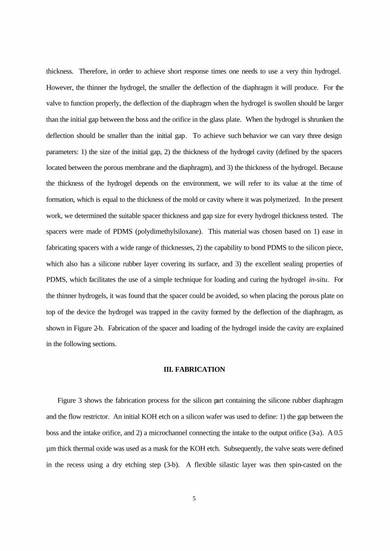
thickness. Therefore, in order to achieve short response times one needs to use a very thin hydrogel.
However, the thinner the hydrogel, the smaller the deflection of the diaphragm it will produce. For the
valve to function properly, the deflection of the diaphragm when the hydrogel is swollen should be larger
than the initial gap between the boss and the orifice in the glass plate. When the hydrogel is shrunken the
deflection should be smaller than the initial gap. To achieve such behavior we can vary three design
parameters: 1) the size of the initial gap, 2) the thickness of the hydrogel cavity (defined by the spacers
located between the porous membrane and the diaphragm), and 3) the thickness of the hydrogel. Because
the thickness of the hydrogel depends on the environment, we will refer to its value at the time of
formation, which is equal to the thickness of the mold or cavity where it was polymerized. In the present
work, we determined the suitable spacer thickness and gap size for every hydrogel thickness tested. The
spacers were made of PDMS (polydimethylsiloxane). This material was chosen based on 1) ease in
fabricating spacers with a wide range of thicknesses, 2) the capability to bond PDMS to the silicon piece,
which also has a silicone rubber layer covering its surface, and 3) the excellent sealing properties of
PDMS, which facilitates the use of a simple technique for loading and curing the hydrogel in-situ. For
the thinner hydrogels, it was found that the spacer could be avoided, so when placing the porous plate on
top of the device the hydrogel was trapped in the cavity formed by the deflection of the diaphragm, as
shown in Figure 2-b. Fabrication of the spacer and loading of the hydrogel inside the cavity are explained
in the following sections.
III. FABRICATION
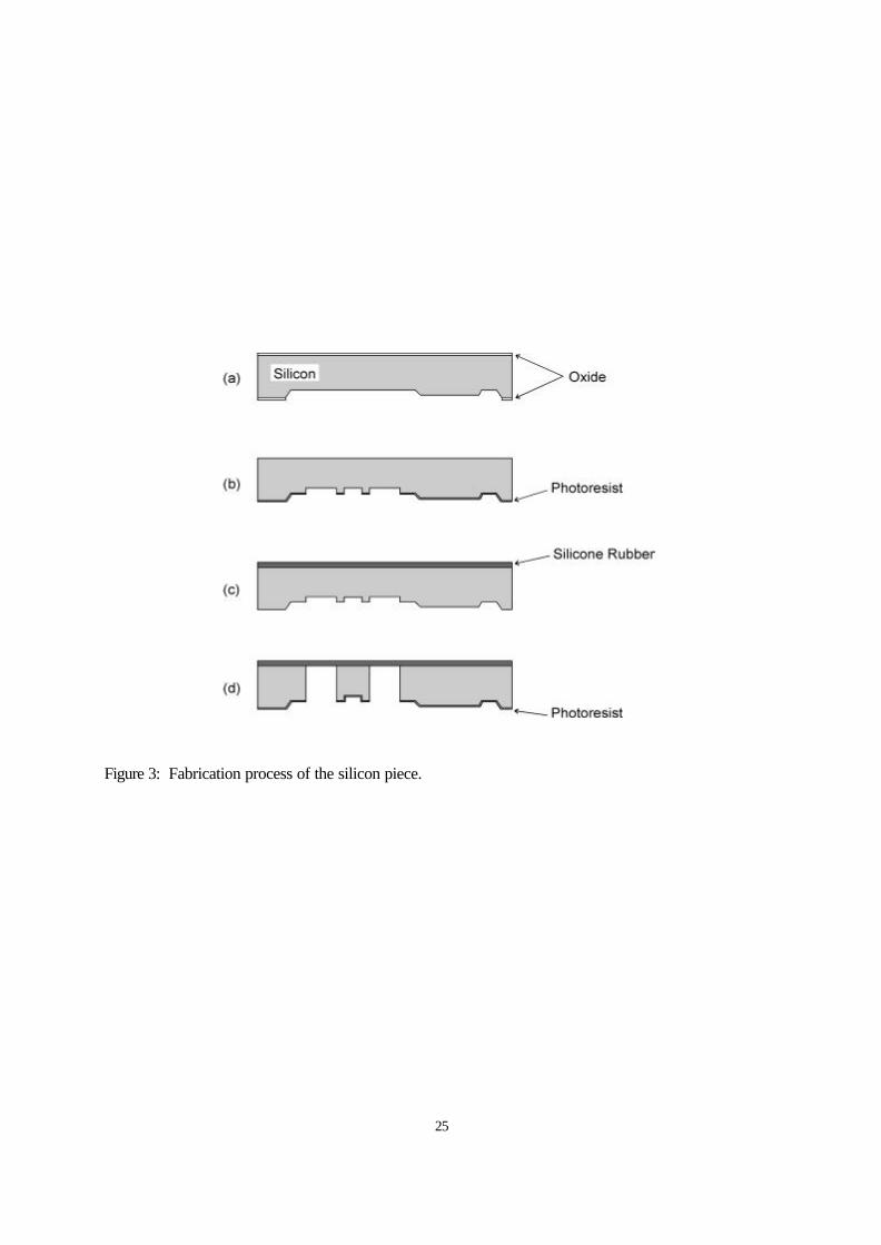
Figure 3 shows the fabrication process for the silicon part containing the silicone rubber diaphragm
and the flow restrictor. An initial KOH etch on a silicon wafer was used to define: 1) the gap between the
boss and the intake orifice, and 2) a microchannel connecting the intake to the output orifice (3-a). A 0.5
µm thick thermal oxide was used as a mask for the KOH etch. Subsequently, the valve seats were defined
in the recess using a dry etching step (3-b). A flexible silastic layer was then spin-casted on the
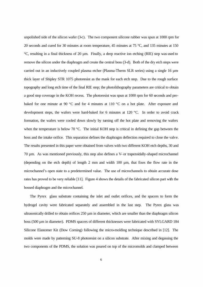
6
unpolished side of the silicon wafer (3-c). The two component silicone rubber was spun at 1000 rpm for
20 seconds and cured for 30 minutes at room temperature, 45 minutes at 75 °C, and 135 minutes at 150
°C, resulting in a final thickness of 20 µm. Finally, a deep reactive ion etching (RIE) step was used to
remove the silicon under the diaphragm and create the central boss (3-d). Both of the dry etch steps were
carried out in an inductively coupled plasma etcher (Plasma-Therm SLR series) using a single 16 µm-
thick layer of Shipley STR 1075 photoresist as the mask for each etch step. Due to the rough surface
topography and long etch time of the final RIE step; the photolithography parameters are critical to obtain
a good step coverage in the KOH recess. The photoresist was spun at 1000 rpm for 60 seconds and pre-
baked for one minute at 90 ºC and for 4 minutes at 110 ºC on a hot plate. After exposure and
development steps, the wafers were hard-baked for 6 minutes at 120 ºC. In order to avoid crack
formation, the wafers were cooled down slowly by turning off the hot plate and removing the wafers
when the temperature is below 70 ºC. The initial KOH step is critical in defining the gap between the
boss and the intake orifice. This separation defines the diaphragm deflection required to close the valve.
The results presented in this paper were obtained from valves with two different KOH etch depths, 30 and
70 µm. As was mentioned previously, this step also defines a V- or trapezoidally-shaped microchannel
(depending on the etch depth) of length 2 mm and width 100 µm, that fixes the flow rate in the
microchannel’s open state to a predetermined value. The use of microchannels to obtain accurate dose
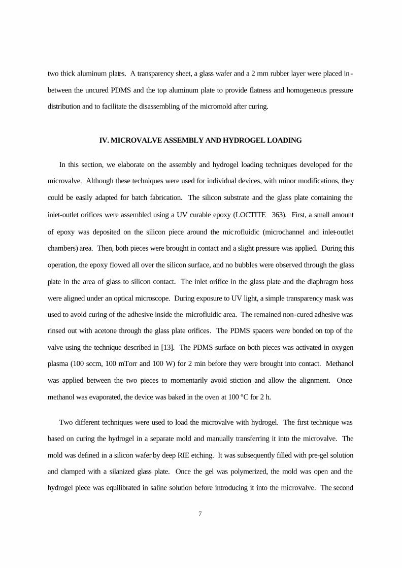
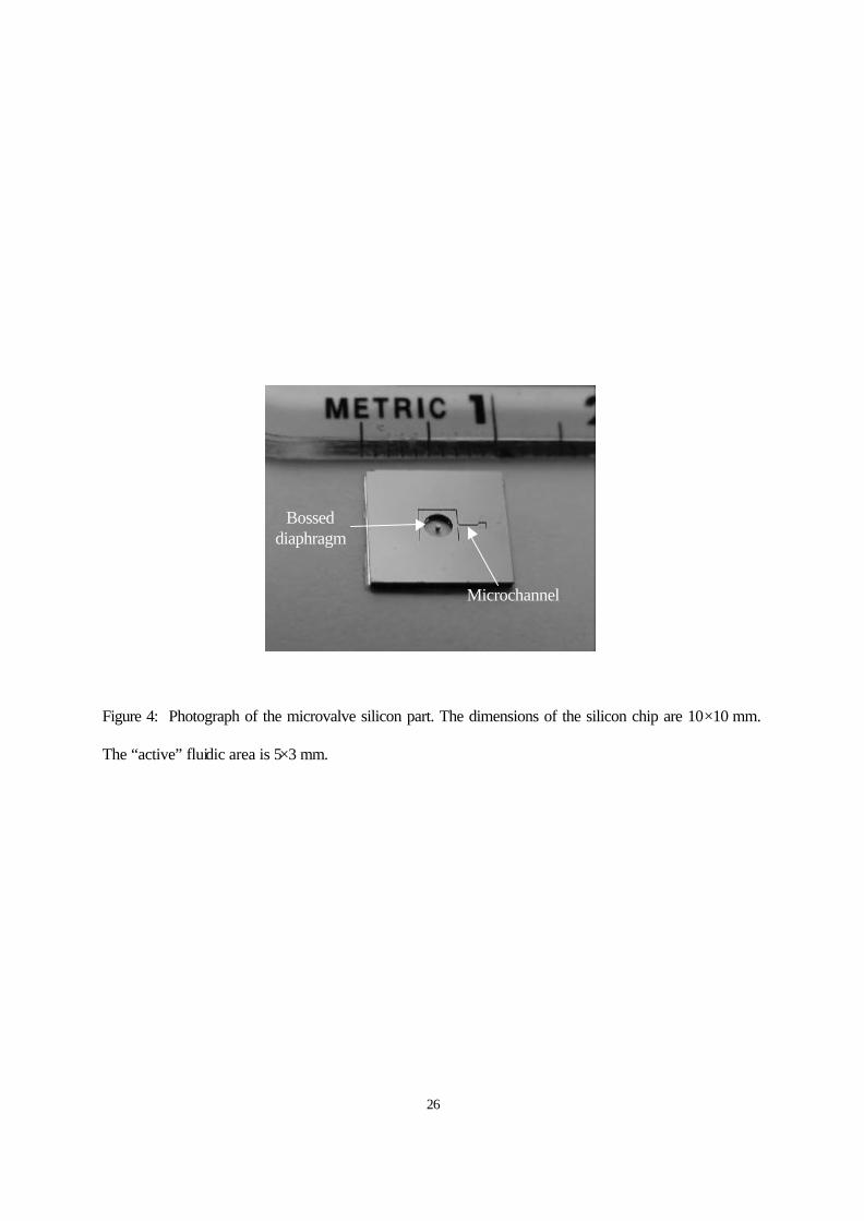
rates has proved to be very reliable [11]. Figure 4 shows the details of the fabricated silicon part with the
bossed diaphragm and the microchannel.
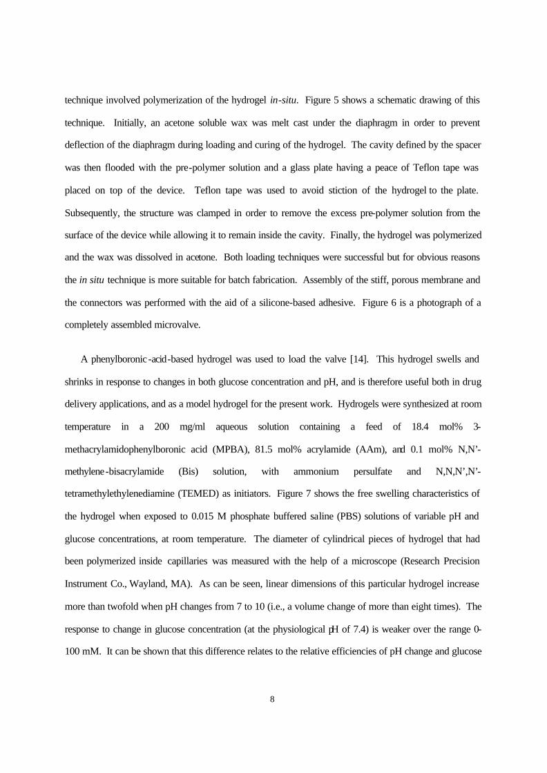
The Pyrex glass substrate containing the inlet and outlet orifices, and the spacers to form the
hydrogel cavity were fabricated separately and assembled in the last step. The Pyrex glass was
ultrasonically drilled to obtain orifices 250 µm in diameter, which are smaller than the diaphragm silicon
boss (500 µm in diameter). PDMS spacers of different thicknesses were fabricated with SYLGARD 184
Silicone Elastomer Kit (Dow Corning) following the micro-molding technique described in [12]. The
molds were made by patterning SU-8 photoresist on a silicon substrate. After mixing and degassing the
two components of the PDMS, the solution was poured on top of the micromolds and clamped between
7
two thick aluminum plates. A transparency sheet, a glass wafer and a 2 mm rubber layer were placed in-
between the uncured PDMS and the top aluminum plate to provide flatness and homogeneous pressure
distribution and to facilitate the disassembling of the micromold after curing.
IV. MICROVALVE ASSEMBLY AND HYDROGEL LOADING
In this section, we elaborate on the assembly and hydrogel loading techniques developed for the
microvalve. Although these techniques were used for individual devices, with minor modifications, they
could be easily adapted for batch fabrication. The silicon substrate and the glass plate containing the
inlet-outlet orifices were assembled using a UV curable epoxy (LOCTITE 363). First, a small amount
of epoxy was deposited on the silicon piece around the microfluidic (microchannel and inlet-outlet
chambers) area. Then, both pieces were brought in contact and a slight pressure was applied. During this
operation, the epoxy flowed all over the silicon surface, and no bubbles were observed through the glass
plate in the area of glass to silicon contact. The inlet orifice in the glass plate and the diaphragm boss
were aligned under an optical microscope. During exposure to UV light, a simple transparency mask was
used to avoid curing of the adhesive inside the microfluidic area. The remained non-cured adhesive was
rinsed out with acetone through the glass plate orifices. The PDMS spacers were bonded on top of the
valve using the technique described in [13]. The PDMS surface on both pieces was activated in oxygen
plasma (100 sccm, 100 mTorr and 100 W) for 2 min before they were brought into contact. Methanol
was applied between the two pieces to momentarily avoid stiction and allow the alignment. Once
methanol was evaporated, the device was baked in the oven at 100 ºC for 2 h.
Two different techniques were used to load the microvalve with hydrogel. The first technique was
based on curing the hydrogel in a separate mold and manually transferring it into the microvalve. The
mold was defined in a silicon wafer by deep RIE etching. It was subsequently filled with pre-gel solution
and clamped with a silanized glass plate. Once the gel was polymerized, the mold was open and the
hydrogel piece was equilibrated in saline solution before introducing it into the microvalve. The second
8
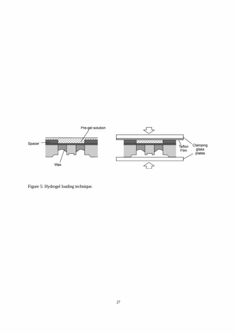
technique involved polymerization of the hydrogel in-situ. Figure 5 shows a schematic drawing of this
technique. Initially, an acetone soluble wax was melt cast under the diaphragm in order to prevent
deflection of the diaphragm during loading and curing of the hydrogel. The cavity defined by the spacer
was then flooded with the pre-polymer solution and a glass plate having a peace of Teflon tape was
placed on top of the device. Teflon tape was used to avoid stiction of the hydrogel to the plate.
Subsequently, the structure was clamped in order to remove the excess pre-polymer solution from the
surface of the device while allowing it to remain inside the cavity. Finally, the hydrogel was polymerized
and the wax was dissolved in acetone. Both loading techniques were successful but for obvious reasons
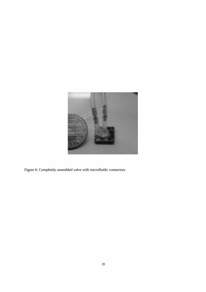
the in situ technique is more suitable for batch fabrication. Assembly of the stiff, porous membrane and
the connectors was performed with the aid of a silicone-based adhesive. Figure 6 is a photograph of a
completely assembled microvalve.
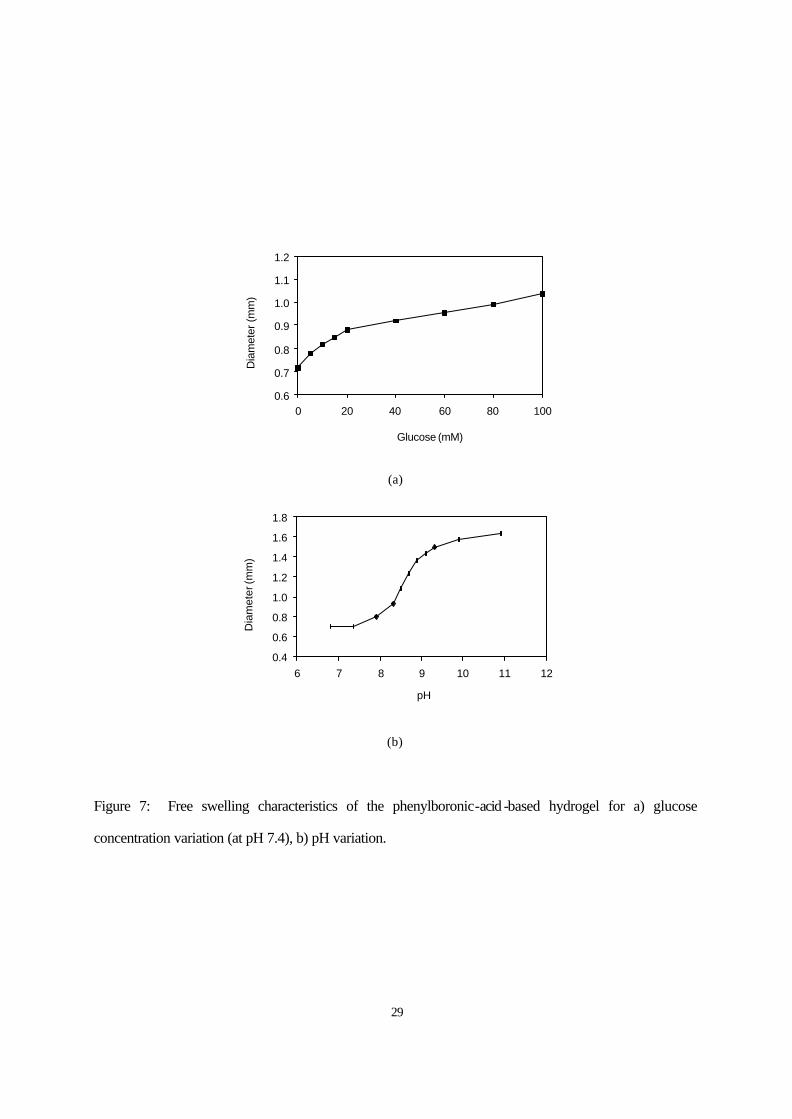
A phenylboronic-acid-based hydrogel was used to load the valve [14]. This hydrogel swells and
shrinks in response to changes in both glucose concentration and pH, and is therefore useful both in drug
delivery applications, and as a model hydrogel for the present work. Hydrogels were synthesized at room
temperature in a 200 mg/ml aqueous solution containing a feed of 18.4 mol% 3-
methacrylamidophenylboronic acid (MPBA), 81.5 mol% acrylamide (AAm), and 0.1 mol% N,N’-
methylene-bisacrylamide (Bis) solution, with ammonium persulfate and N,N,N’,N’-
tetramethylethylenediamine (TEMED) as initiators. Figure 7 shows the free swelling characteristics of
the hydrogel when exposed to 0.015 M phosphate buffered saline (PBS) solutions of variable pH and
glucose concentrations, at room temperature. The diameter of cylindrical pieces of hydrogel that had
been polymerized inside capillaries was measured with the help of a microscope (Research Precision
Instrument Co., Wayland, MA). As can be seen, linear dimensions of this particular hydrogel increase
more than twofold when pH changes from 7 to 10 (i.e., a volume change of more than eight times). The
response to change in glucose concentration (at the physiological pH of 7.4) is weaker over the range 0-
100 mM. It can be shown that this difference relates to the relative efficiencies of pH change and glucose
9
concentration in modulating hydrogel charge over the respective ranges of observation. The hydrogel
shows maximum sensitivity to glucose in the range of human glucose levels (<3.5 mM for hypoglycemia,
~5 mM for normoglycemia and >7 mM for hyperglycemia).
V. TEST RESULTS AND DISCUSSION
Before assembling and testing the complete microvalve, some preliminary tests were performed in
order to characterize the individual components. First, the mechanical behavior of the silicone diaphragm
was evaluated. The silicon piece containing the diaphragm was mounted in a fixture that permits the
application of pressure to one side while allowing the deflection to be observed under the microscope on
the opposite side. Deflections of up to 100 µm were observed with less than 1 kPa applied pressure,
which confirms that the diaphragm will not oppose much force to the hydrogel expansion. A second
characterization test was performed in order to measure the diaphragm deflection produced by the
hydrogel. In these experiments, the hydrogel was cured in-situ using PDMS spacers of various
thicknesses. A partially assembled valve (without the glass plate) was then mounted in a fixture that
permits the wetting of the porous membrane side in a solution while observing the deflection with a
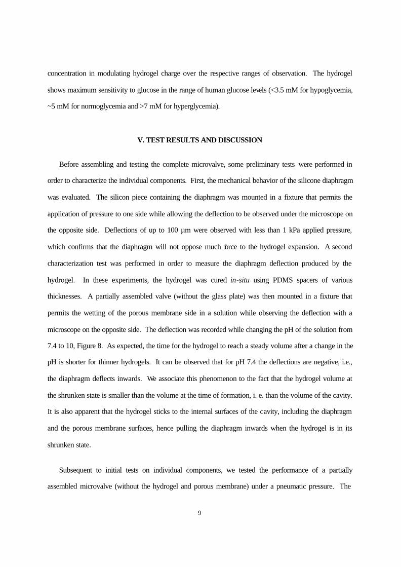
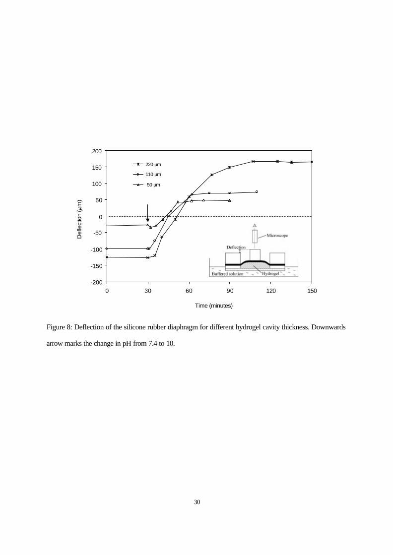
microscope on the opposite side. The deflection was recorded while changing the pH of the solution from
7.4 to 10, Figure 8. As expected, the time for the hydrogel to reach a steady volume after a change in the
pH is shorter for thinner hydrogels. It can be observed that for pH 7.4 the deflections are negative, i.e.,
the diaphragm deflects inwards. We associate this phenomenon to the fact that the hydrogel volume at
the shrunken state is smaller than the volume at the time of formation, i. e. than the volume of the cavity.
It is also apparent that the hydrogel sticks to the internal surfaces of the cavity, including the diaphragm
and the porous membrane surfaces, hence pulling the diaphragm inwards when the hydrogel is in its
shrunken state.
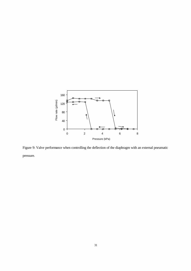
Subsequent to initial tests on individual components, we tested the performance of a partially
assembled microvalve (without the hydrogel and porous membrane) under a pneumatic pressure. The
10
assembly was mounted in a fixture that permits the application of a pneumatic pressure to the diaphragm
external side, while measuring the flow from the inlet to the outlet. The flow-through liquid was de-
ionized water from a water column whose constant height (60 cm) set the hydraulic pressure at the inlet at
5.9±0.2 kPa (the error value has been added to account for the variations of the water level in the
reservoir as it was emptied by the flow and manually refilled every few minutes). In the open state, the
pressure at the inlet slightly decreased due to the flow resistance of the tubing, the valve connectors and
the inlet orifice in the glass plate. Using the Hagen-Poiseuille law [11] this resistance was estimated to be
2.28 Pa/µl/min (producing 0.32 kPa of pressure drop for a flow of 140 µl/min). Flow rate was calculated
from the velocity of an air bubble injected in a capillary of known diameter connected to the outlet.
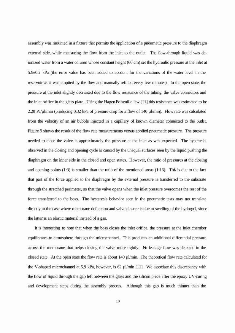
Figure 9 shows the result of the flow rate measurements versus applied pneumatic pressure. The pressure
needed to close the valve is approximately the pressure at the inlet as was expected. The hysteresis
observed in the closing and opening cycle is caused by the unequal surfaces seen by the liquid pushing the
diaphragm on the inner side in the closed and open states. However, the ratio of pressures at the closing
and opening points (1:3) is smaller than the ratio of the mentioned areas (1:16). This is due to the fact
that part of the force applied to the diaphragm by the external pressure is transferred to the substrate
through the stretched perimeter, so that the valve opens when the inlet pressure overcomes the rest of the
force transferred to the boss. The hysteresis behavior seen in the pneumatic tests may not translate
directly to the case where membrane deflection and valve closure is due to swelling of the hydrogel, since
the latter is an elastic material instead of a gas.
It is interesting to note that when the boss closes the inlet orifice, the pressure at the inlet chamber
equilibrates to atmosphere through the microchannel. This produces an additional differential pressure
across the membrane that helps closing the valve more tightly. No leakage flow was detected in the
closed state. At the open state the flow rate is about 140 µl/min. The theoretical flow rate calculated for
the V-shaped microchannel at 5.9 kPa, however, is 62 µl/min [11]. We associate this discrepancy with
the flow of liquid through the gap left between the glass and the silicon piece after the epoxy UV-curing
and development steps during the assembly process. Although this gap is much thinner than the
11
microchannel depth, it turns out to be much wider (1 mm) and shorter (1 mm), and thus contributes
considerably to the total flow. The feature in the transparency mask used to avoid curing the glue inside
the microfluidic area was defined larger than the mentioned area (~0.5 mm in all directions) in order to
facilitate alignment, which was performed manually. If an accurate and repetitive flow rate at the open
state is desired, the assembling process should be improved by using a better alignment system and
providing a better glue thickness control. This will also contribute to obtain a more repetitive gap
between boss and inlet orifice, which is augmented by the epoxy gap.
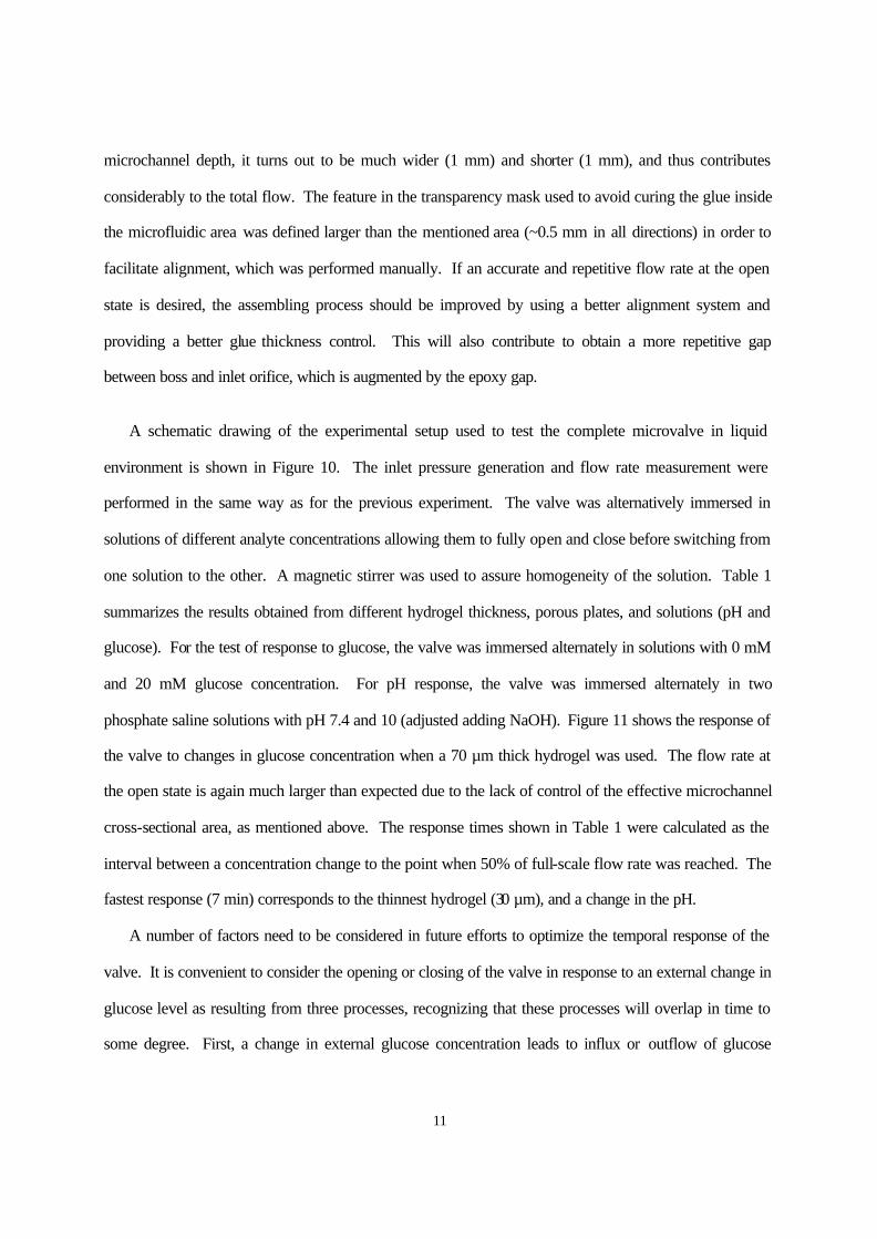
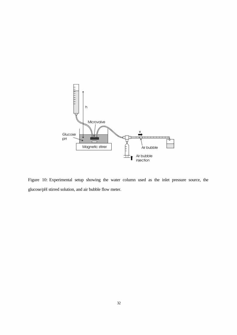
A schematic drawing of the experimental setup used to test the complete microvalve in liquid
environment is shown in Figure 10. The inlet pressure generation and flow rate measurement were
performed in the same way as for the previous experiment. The valve was alternatively immersed in
solutions of different analyte concentrations allowing them to fully open and close before switching from
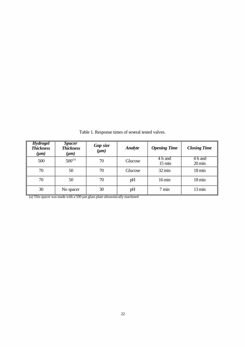
one solution to the other. A magnetic stirrer was used to assure homogeneity of the solution. Table 1
summarizes the results obtained from different hydrogel thickness, porous plates, and solutions (pH and
glucose). For the test of response to glucose, the valve was immersed alternately in solutions with 0 mM
and 20 mM glucose concentration. For pH response, the valve was immersed alternately in two
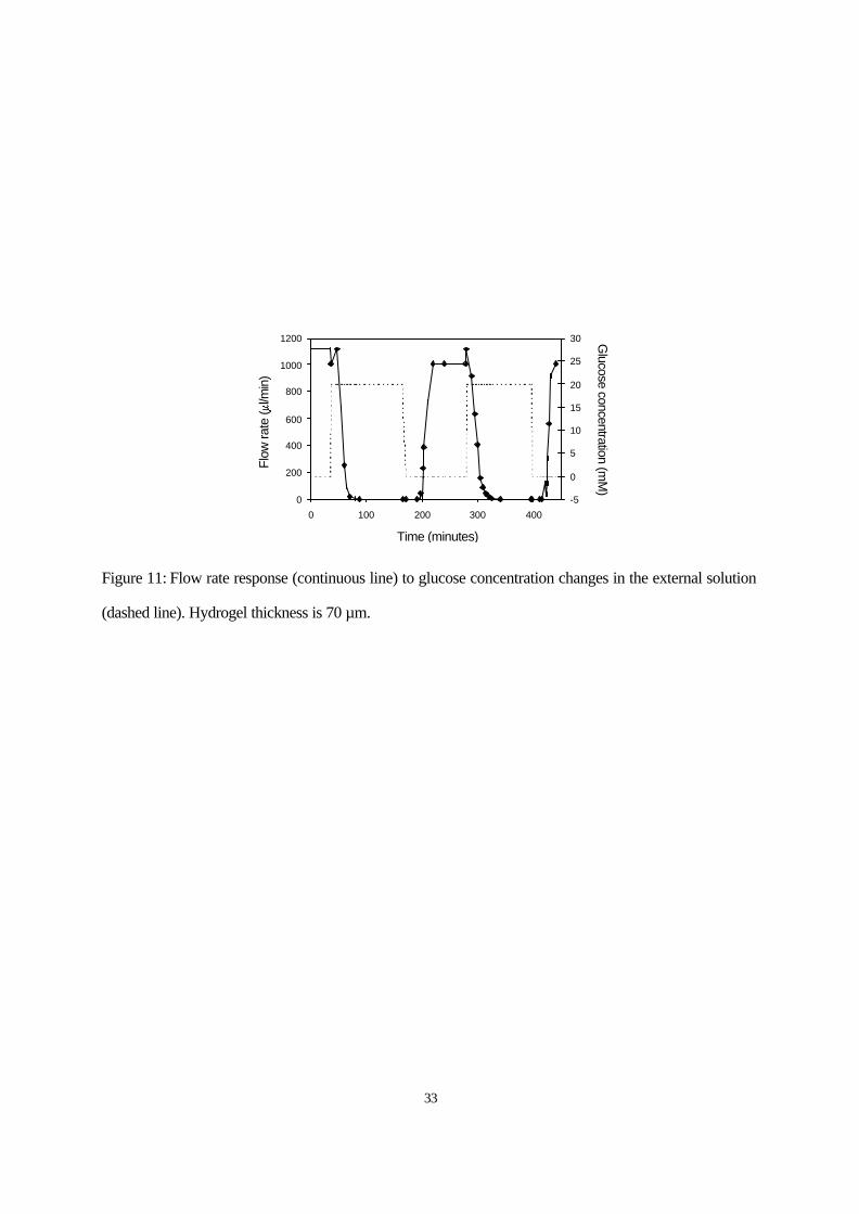
phosphate saline solutions with pH 7.4 and 10 (adjusted adding NaOH). Figure 11 shows the response of
the valve to changes in glucose concentration when a 70 µm thick hydrogel was used. The flow rate at
the open state is again much larger than expected due to the lack of control of the effective microchannel
cross-sectional area, as mentioned above. The response times shown in Table 1 were calculated as the
interval between a concentration change to the point when 50% of full-scale flow rate was reached. The
fastest response (7 min) corresponds to the thinnest hydrogel (30 µm), and a change in the pH.
A number of factors need to be considered in future efforts to optimize the temporal response of the
valve. It is convenient to consider the opening or closing of the valve in response to an external change in
glucose level as resulting from three processes, recognizing that these processes will overlap in time to
some degree. First, a change in external glucose concentration leads to influx or outflow of glucose
12
through the rigid porous membrane. At quasi-steady-state, which should be rapidly achieved in thin
membranes, flux will be inversely proportional to membrane thickness, and will increase with membrane
porosity. Second, glucose must diffuse through the gel and (reversibly) bind to pendant PBA groups.
Assuming that the binding reaction is relatively fast compared to diffusion through the thickness of the
gel (a reasonable assumption in many diffusion-reaction systems), the characteristic time of this step
should scale as the square of the gel’s thickness [15-20]. Third, the gel’s volume must change in response
to the chemomechanical stresses, which develop according to the new charge environment and transport
of ions in and out of the gel, sometimes with the assistance of body buffers [17-20]. Taken by itself, the
swelling or deswelling process, which entails transport of water into or out of the gel, also has a
characteristic time that scales with the square of gel thickness [15-19].
As the hydrogel swells or deswells, the boss moves across the gap, either closing or opening the
channel. These mechanical processes complicate the simple picture just presented. When the valve is
open, swelling of the gel is opposed primarily by the pressure of the flowing stream, and the time taken to
close the gap should decrease with original gap distance. Upon closure, swelling pressure will continue to
grow until the gel reaches chemomechanical equilibrium, and during this phase the annular part of the
PDMS diaphragm will stretch further and bulge into the inlet chamber. Reopening of the gap, then, will
not occur until the swelling pressure of the gel drops below the opening pressure. The amount of swelling
“overpressure” developed will depend on both the chemical composition of the gel and the geometry of
the overall device structure.
Taken together, these arguments suggest that response time can be altered in a number of ways, but a
delicate interaction between the gel’s chemo-mechanics and various geometric parameters (membrane
thickness, membrane porosity, hydrogel thickness, gap distance) must be taken into consideration.
Despite the complexity, we may conclude that by reducing the thicknesses of the hydrogel, the response
time can be reduced. It should be mentioned, however, that we observed a decrease in the yield and
reliability of the valves along with the hydrogel thickness reduction. The valves loaded with a 30 µm-
thick hydrogel showed very asymmetrical opening/closing times and stopped functioning after a few
13
cycles. In these valves the hydrogel thickness is about two orders of magnitude smaller than its diameter,
which is equal to the diaphragm diameter (1800 µm). This may lead to poor mechanical stability. Due to
its deformability, the hydrogel can be squeezed out of the boss area towards the flexible rubber area
where it finds less opposition to swelling, and stresses produced may lead to breakage of the gel. Thus, in
order to further reduce the thickness of the hydrogel a new design with a smaller diaphragm diameter
should be considered.
One may think intuitively that reduction of thickness and diameter of the hydrogel will lead to valves
with a smaller pressure capability. Nevertheless, the osmotic pressure developed within the hydrogel
does not depend on its dimensions. Yet, the absolute volume change, and hence, the diaphragm
deflection, will decrease proportionally with the hydrogels dimensions, so a smaller closing gap will be
necessary. This will make more difficult the “tuning” of the valve for closing at the desired glucose level.
A smaller gap will also limit the liquid flow-rate attainable for a given inlet pressure due to an increase of
flow resistance. Another possible limitation to the reduction of dimensions would be an increase in the
stiffness of the diaphragm. However, due to the low Young’s modulus of the silicone rubber, there is still
a considerable margin for diameter reduction before this becomes a problem. For example, according to
the plate theory [21] if the bossed membrane dimensions are reduced five times (keeping the membrane
thickness of 20 µm); a deflection of 9 µm is obtained with only 1 kPa applied pressure. On the other hand
reduction of dimensions can help to prevent diaphragm tear during assembly and operation of the valve,
which was one of the main causes of failure. Another possible way to decrease the valve response time
would be using a faster hydrogel. For example, it has been shown that hydrogels with lower degree of
cross-linking or with porous structures exhibit faster responses [22], although at the expenses of a lower
swelling pressure.
14
VI. CONCLUSIONS
In this paper, we have reported on the design, fabrication, and testing of a smart hydrogel-based
microvalve for active flow control in microfluidic systems. An environmentally sensitive hydrogel was
sandwiched between a stiff porous membrane and a flexible silicone rubber diaphragm. Exposure to an
external variable environment (e.g., different glucose concentrations, pH) resulted in a reversible
swelling-deswelling of the hydrogel, deflection of the silicone diaphragm, and opening/closing of the
valve intake orifice. We demonstrated that reasonable response times can be achieved by reducing the
hydrogel thickness. An opening response time as low as 7 minutes was obtained using a 30 µm hydrogel
in response to a sudden pH change. As indicated initially, a primary potential application of the
responsive hydrogel-controlled microvalve will be glucose-sensitive, closed loop control of insulin
delivery in the treatment of diabetes. Because of the critical nature of the insulin response, the simple
valve structure described here may have to be augmented with features that guarantee, for example, a
limit in the amount of insulin delivered during a pulse. Moreover, in the present implementation, rise and
fall in glucose concentration leads to closing and opening of the microfluidic valve, respectively. For
insulin delivery, the opposite response is desired. While reversal of valve “polarity” might be achieved
by mechanical redesign of the valve, it may be simpler to design hydrogels that shrink instead of swell
with increasing glucose concentration [14].
15
ACKNOWLEDGEMENTS
The authors would like to thank the staff of the Microtechnology Laboratory of the University of
Minnesota for their assistance in fabrication. Funding for this project was provided by the Spanish
Ministry of Science and Technology, the University of Minnesota Drug Delivery Center, and the
Graduate school of the University of Minnesota.
16
REFERENCES
[1] T. Tanaka, D. Fillmore, and Shao-Tang Sun, I. Nishio, G. Swislow, and A. Shah, “Phase Transitions
in Ionic Gels,” Phys. Rev. Lett., Vol. 45, pp. 1936-1939, 1980.
[2] T. Tanaka, “Gels,” Scientific American, pp. 124-138, January 1981.
[3] Y. Osada, and S. B. Russ-Murphy, “Intelligent Gels,” Scientific American, pp. 82-87, May 1993.
[4] Y. Osada, and J. Gong, “Stimuli-Responsive Polymer Gels and Their Applications to
Chemomechanical Systems,” Prog. Polym. Sci., Vol. 18, pp. 187-226, 1993.
[5] K.F. Arndt, D. Kuckling, and A. Richter, “Application of Sensitive Hydrogels in Flow Control,”
Polym. Adv. Technol., Vol. 11, pp. 496-550, 2000.
[6] R. H. Liu, Q. Yu, and D. J. Beebe, “Fabrication and Characterization of Hydrogel-Based
Microvalves,” J. Microelectromech. Syst., Vol. 11, pp. 45-53, 2002.
[7] Q. Yu, J. M. Bauer, J. S. Moore, and D. J. Beebe, “Responsive Biomimetic Hydrogel Valve for
Microfluidics,” App. Phys. Lett., Vol. 78, pp. 2589-2591, 2001.
[8] X. Cao, S. Lai, and L. J. Lee, “Design of a Self-Regulated Drug Delivery Device,” Biomedical
Microdevices, Vol. 3:2, pp. 109-118, 2001.
[9] A. Baldi, Y. Gu, P. E. Loftness, R. A. Siegel, B. Ziaie, "A Hydrogel-Actuated smart Microvalve With
A Porous Diffusion Barrier Back-Plate For Active Flow Control", in IEEE MEMS Conference
Technical Digest 2002, pp. 105-108, 2002.
[10] Y. Gu, A. Baldi, B. Ziaie, and R. A. Siegel, "Modulation of Drug Delivery Rate by Hydrogel-
Incorporating MEMS Devices", in Proc. 2nd Annual International IEEE-EMBS Special Topic
Conference on Microtechnologies in Medicine & Biology , pp. 406-409, 2002.
[11] M. Richter, P. Woias, and D. Wieβ, “Microchannels for Applications in Liquid Dosing and Flow-
Rate Measurement,” Sensors and Actuators A, Vol. 62, pp. 480-483, 1997.
17
[12] B. Jo, L. M. Van Lerberghe, K. M. Motsegood, and D. J. Beebe, “Three-Dimensional Micro-Channel
Fabrication in Polydimethilsiloxane (PDMS) Elastomer,” J. Microelectromech. Syst., Vol. 9, pp. 76-
81, 2000.
[13] K. Hosokawa and R. Maeda, “A Pneumatically-Acutated Three-Way Microvalve Fabricated with
Polydimethylsiloxane using the Membrane Transfer Technique,” J. Micromech. Microeng., Vol. 10,
pp. 415-420, 2000.
[14] Y. Gu and R. A. Siegel, “Swelling Behaviors of Phenylboronic Acid Hydrogel in Glucose Solution,”
in Proc. 28th International Symposium on Controlled Release of Bioactive Materials, San Diego, CA,
2001, paper no 668.
[15] S.R. Eisenberg, and A.J. Grodzinsky, “The kinetics of chemically induced nonequilibrium swelling
of articular cartilage and corneal stroma”, J. Biomech. Eng., Vol. 109, pp. 79-89, 1987.
[16] P.E. Grimshaw, J.H. Nussbaum, A.J. Grodzinsky, and M.L. Yarmush, “Kinetics of Electrically and
Chemically Induced Swelling of Polyelectrolyte Gels”, J. Chem. Phys., Vol. 93, pp. 4462-4472,
1990.
[17] M.J. Lesho, and N.J. Sheppard, “A Metod for Studying Swelling Kinetics Based on Measurement of
Electrical Conductivity”, Polym. Gels Networks, Vol. 5, pp. 503-523, 1997.
[18] A. English, T. Tanaka, and E.R. Edelman, “Equilibrium and non-equilibrium phase transitions in
copolymer polyelectrolyte hydrogels”, J.Chem. Phys., Vol. 107, pp. 1645-1654, 1997.
[19] E. Achilleos, K. Christodoulou, and I.G. Kevrekidis, “A Transport Model for Swelling of
Polyelectrolyte Gels in Constrained Geometries”, Comp. Theor. Polym. Sci., Vol. 11, pp. 63-80,
2001.
[20] S.K. De, N.R. Aluru, B. Johnson, W.C. Crone, and D.J. Beebe, “Equilibrium Swelling and Kinetics
of pH-Responsive Hydrogels: Models, Experiments, and Simulations” J. Microelectromech. Syst.,
Vol. 9, pp. 76-81, 2002.
[21] M. Di Giovanni, Flat and corrugated diaphragm design handbook . New York: Marcel Dekker,
1982, p. 147.
18
[22] B. Zhao and J. S. Moore, “Fast pH- and Ionic Strength-Responsive Hydrogels in Microchannels”,
Langmuir, Vol. 17, pp. 4758-4763, 2001.
19
LIST OF FIGURES
Figure 1: Schematic drawing of the valve basic structure and working principle.
Figure 2: Schematic drawing of the microvalve cross-section a) with spacer, b) without spacer (thinner
hydrogel).
Figure 3: Fabrication process of the silicon piece.
Figure 4: Photograph of the microvalve silicon part. The dimensions of the silicon chip are 10×10 mm.
The “active” fluidic area is 5×3 mm.
Figure 5: Hydrogel loading technique.
Figure 6: Completely assembled valve with microfluidic connectors.
Figure 7: Free swelling characteristics of the phenylboronic -acid -based hydrogel for a) glucose
concentration variation (at pH 7.4), b) pH variation.
Figure 8: Deflection of the silicone rubber diaphragm for different hydrogel thickness. Downwards arrow
marks the change in pH from 7.4 to 10.
Figure 9: Valve performance when controlling the deflection of the diaphragm with an external pneumatic
pressure.
20
Figure 10: Experimental setup showing the water column used as the inlet pressure source, the
glucose/pH stirred solution, and air bubble flow meter.
Figure 11: Flow rate response (continuous line) to glucose concentration changes in the external solution
(dashed line). Hydrogel thickness is 70 µm.

21
LIST OF TABLES
Table 1. Response times of several tested valves.
22
Table 1. Response times of several tested valves.
Hydrogel Thickness
(µm)
Spacer Thickness
(µm)
Gap size (µm) Analyte Opening Time Closing Time
500 500 (a) 70 Glucose 4 h and 15 min
4 h and 20 min
70 50 70 Glucose 32 min 18 min
70 50 70 pH 16 min 18 min
30 No spacer 30 pH 7 min 13 min
(a) This spacer was made with a 500 µm glass plate ultrasonically machined
23
(a)
(b)
Figure 1: Schematic drawing of the valve cross-section and working principle.
24
(a)
(b)
Figure 2: Schematic drawing of the microvalve cross-section a) with spacer, b) without spacer (thinner
hydrogel).
25
Figure 3: Fabrication process of the silicon piece.
26
Figure 4: Photograph of the microvalve silicon part. The dimensions of the silicon chip are 10×10 mm.
The “active” fluidic area is 5×3 mm.
Microchannel
Bossed diaphragm
27
Figure 5: Hydrogel loading technique.
28
Figure 6: Completely assembled valve with microfluidic connectors.
29
0.6
0.7
0.8
0.9
1.0
1.1
1.2
0 20 40 60 80 100
Glucose (mM)
Dia
met
er (m
m)
(a)
0.4
0.6
0.8
1.0
1.2
1.4
1.6
1.8
6 7 8 9 10 11 12
pH
Dia
met
er (m
m)
(b)
Figure 7: Free swelling characteristics of the phenylboronic-acid -based hydrogel for a) glucose
concentration variation (at pH 7.4), b) pH variation.
30
-200
-150
-100
-50
0
50
100
150
200
0 30 60 90 120 150
220 µm
110 µm
50 µm
Time (minutes)
Def
lect
ion
(m
)
Figure 8: Deflection of the silicone rubber diaphragm for different hydrogel cavity thickness. Downwards
arrow marks the change in pH from 7.4 to 10.
31
0
40
80
120
160
0 2 4 6 8
Pressure (kPa)
Flow
rat
e (µ
l/min
)
Figure 9: Valve performance when controlling the deflection of the diaphragm with an external pneumatic
pressure.
32
Figure 10: Experimental setup showing the water column used as the inlet pressure source, the
glucose/pH stirred solution, and air bubble flow meter.
33
0
200
400
600
800
1000
1200
0 100 200 300 400-5
0
5
10
15
20
25
30
Time (minutes)
Flow
rate
(l/m
in)
Glucose concentration (m
M)
Figure 11: Flow rate response (continuous line) to glucose concentration changes in the external solution
(dashed line). Hydrogel thickness is 70 µm.