a java h.263 decoder implementationjauvane/papers/h263javadecoder.pdffigure 2.1: block diagram for...
TRANSCRIPT

* Jauvane C. de Oliveira is sponsored by CAPES, the Brazilian Ministry of Education Agency. Compulsory Statement: “Bolsista Capes - Brasilia / Brasil”
Jauvane Cavalcante de Oliveira*
A Java H.263 Decoder Implementation
Project report presented as part of therequirements for the Image Processingand Communication course, ELG5378,winter 1997 term.
Prof.: Dr. Sethuraman Panchanathan
Electrical and Computer Engineering Department
UNIVERSITY OF OTTAWA
Ottawa, April 15, 1997
i
Abstract
As the result of the work done as a project for the Image Processing and Communications
course in the winter of 1997, this report describes the implementation of a Java H.263
video decoder. The Decoder allows H.263 coded video streams to be decoded and
displayed in a window on any Java enabled machine. It shows that it’s possible to create a
conferencing environment just using Java Enabled Browsers.
Keywords: ITU-T H.263, Java, ITU-T H.324, Video Codec.

ii
Table of Contents
1. INTRODUCTION..........................................................................................................................1
2. THE ITU-T H.324 RECOMMENDATION .....................................................................................62.1. SCOPE........................................................................................................................................................72.2. FUNCTIONAL ELEMENTS............................................................................................................................8
3. THE ITU-T H.263 RECOMMENDATION ...................................................................................113.1. HISTORIC.................................................................................................................................................113.2. H.263 X H.261 ........................................................................................................................................143.3. THE H.263 SOURCE CODER....................................................................................................................19
3.3.1. Prediction .......................................................................................................................................203.3.2. Motion compensation......................................................................................................................203.3.3. Quantization ...................................................................................................................................213.3.4. Zig-Zag Scan...................................................................................................................................21
3.4. SEMANTIC AND SYNTAX ..........................................................................................................................223.4.1. Picture Layer ..................................................................................................................................223.4.2. Group of Block Layer .....................................................................................................................263.4.3. Macroblock Layer...........................................................................................................................283.4.4. Block Layer.....................................................................................................................................31
4. THE JAVA PARADIGM ..............................................................................................................354.1. JAVA ’S ARCHITECTURE...........................................................................................................................354.2. APPROACHES FOR APPLICATIONS FOR THE WEB......................................................................................374.3. JAVA ADVANTAGES AND DISADVANTAGES .............................................................................................37
5. JAVA H.263 IMPLEMENTATION...............................................................................................395.1. CODEC ARCHITECTURE...........................................................................................................................39
6. CONCLUSION............................................................................................................................456.1. FURTHER RECOMMENDATION AND FUTURE WORK.................................................................................45
REFERENCES...............................................................................................................................47

iii
List of Figures
FIGURE 2.1: BLOCK DIAGRAM FOR H.324 MULTIMEDIA SYSTEMS .........................................7
FIGURE 2.2: BLOCK DIAGRAM FOR H.320 MULTIMEDIA SYSTEMS .........................................8
FIGURE 3.1: INTERFACE LBL-UCB/VIC ......................................................................................12
FIGURE 3.2: INTERFACE INRIA/IVS ............................................................................................13
FIGURE 3.3: INTERFACE PUC-RIO/TVS .....................................................................................14
FIGURE 3.4: BLOCK DIAGRAM OF THE H.263 VIDEO CODEC.................................................15
FIGURE 3.5: BLOCK DIAGRAM FOR H.261 VIDEO CODEC ......................................................15
FIGURE 3.6: H.263 PICTURE FORMAT RESOLUTIONS ............................................................16
FIGURE 3.7: LUMINANCE AND CHROMINANCE POSITIONS INSIDE A MACROBLOCK ........16
FIGURE 3.8: ARRANGEMENT OF BLOCKS IN A MACROBLOCK..............................................17
FIGURE 3.9: SYNTAX DIAGRAM FOR VIDEO BITSTREAM .......................................................18
FIGURE 3.10: SOURCE CODER ..................................................................................................19
FIGURE 3.11: ZIG-ZAG SCANNING .............................................................................................21
FIGURE 3.12: PICTURE LAYER STRUCTURE............................................................................22
FIGURE 3.13: PTYTE BITS ...........................................................................................................23
FIGURE 3.14: DBQUANT CODES AND RELATION BETWEEN QUANT AND BQUANT ...........25
FIGURE 3.15: STRUCTURE OF GOB LAYER..............................................................................26
FIGURE 3.16: STRUCTURE OF MACROBLOCK LAYER ............................................................28
FIGURE 3.17: STRUCTURE OF BLOCK LAYER..........................................................................31
FIGURE 3.18: RECONSTRUCTION LEVELS FOR INTRA-MODE DC COEFFICIENT ...............31
FIGURE 3.19: VLC TABLE FOR TCOEF.......................................................................................34
FIGURE 3.20: FLC TABLE FOR RUNS AND LEVELS..................................................................34
FIGURE 4.1: THE JAVA ARCHITECTURE ...................................................................................36
FIGURE 4.2: THE STEPS REQUIRED TO RUN A PROGRAM WRITTEN IN JAVA....................36
FIGURE 5.1: JAVA VIDEO CODEC ARCHITECTURE .................................................................40
FIGURE 5.2: H.263 × H.261...........................................................................................................43

1
Chapter I
1. Introduction
People, by their social nature, need to have interaction with others in order to be able to
acquire knowledge. With ever advancing of social structure of humanity, there is an
increased demand for communication in order to overcome the geographical distances. In
order to accommodate the need for communication, several methods were created to
facilitate that exchange, starting from the smoke signals exchanged by our ancestors till
the actual telecommunication devices, such as the telephone and the Internet.
However, when a meeting among a group of persons is required, to discuss any matter, it
is required that all of them relocate to a common place. This introduces lot of problems,
such as money spent, security problems, scheduling and other problem. As an example,
consider the world meeting ECO 92, held in Rio de Janeiro, Brazil, where the majority of
head of states met to discuss ecological issues.
With the objective to improve this scenario, several research groups began studies to
develop a set of communication services, called teleconferencing services.
Teleconferencing Services are defined [SoMB 88, Fluc 95] as a set of telecommunication
facilities that allow the participants in two or more different places, to establish a bi-

2
directional link through communication electronic devices, while sharing simultaneously
their audio-visual environment, by having the impression that they are all in the same
place.
The teleconferencing services are classified by the literature [H.200, SoMB 88, Fluc 95],
as:
• Audio Conferencing - Service where just audio and control signals are exchanged
among the participants;
• Audio-Documentational Conferencing - Service close to the Audio Conferencing
service; however, the treatment of text documents should be supported;
• Audio-Graphic Conferencing - Service that allows transmissions of audio, control,
text documents and static images;
• Freeze-Frame Videoconferencing - Service close to the Audio-Graphic
Conferencing, adding the periodic exchange of static images of the participants (a
very low frame rate video exchange should be classified as being this service);
• Tele-seminar - Service that broadcasts the events (audio and video) from a
particular place to all participants; however the return path just allows audio
signal transmission;
• Videoconferencing - Service similar to the Audio-Graphic Conferencing adding
the real time video exchange among the participants.

3
Some other audiovisual services [H.200], having similar characteristics from the
teleconferencing services share the same standards. For instance:
• Conventional Telephony - It is included to address the interoperability with the
other services;
• Videophony - Service that allows bi-directional point-to-point transmission of
audio and video between the two participants. Usually, the video quality is lower
than the Videoconferencing one;
• Tele-Surveillance - Service that allows unidirectional transmission of signals in
order to make possible the observation of some environments. At this time, there
is no standardization proposed to this service.
The videoconferencing service is worthy of special attention, since all others can be
defined as particular cases of videoconferencing, for instance the Audio-Graphic
Conferencing can be defined as a videoconferencing without video transmission.
As a result of the research developed in the previous years, some teleconferencing
prototypes, particularly videoconferencing, were introduced. However, these prototypes
present some limitations. Many of them don’t adhere to accorded standards, and are
limited to the audio and video transmission without synchronism.
In order to be able to exchange information with others, a system has to adhere to the
established standards for each media, such as audio, video, data, as well as for the
4
multimedia/hypermedia object interchange. The international standardization
organizations (ISO1 and ITU-T2) suggest H.261 [H.261] or H.263 [Draft H.263] for real
time video codification, MPEG, MPEG-2 or MPEG-4 [Fluc 95] for video
storage/retrieval, JPEG [Wall 91] for static image codification, G.711, G.722, G.728,
G.723 [G.711, G.722, G.728, Draft G.723], MHEG [MHEG 95]for
multimedia/hypermedia interchange. H.221 or H.223 [H.221, H.223] for framing, H.245
[Draft H.245] for multimedia control signaling, as well as security mechanisms [Schn
95]. A more detailed description of the videoconferencing scenario can be found in [Oliv
96].
Portability is a very common problem that occurs when a multimedia system is being
implemented. Usually, a version for each machine has to be written, and it is really hard
to manage this kind of code: for instance, imagine if after finishing the coding for ten
different machines, some improvement is going to be done in the system; unfortunately,
this modification has to be done in each of the ten codes, which is not a trivial task. Some
few years ago, Sun Microsystems introduced a new language that eliminates the
portability problem. This language, called JAVA, allows a program to be written just
once and to run on the ten machines with no modifications in the code. Because of this,
that improvement can be easily done, since there is just one code to be updated.
This project report presents an H.263 Java decoder that can be used to allow the required
standard video transmission by any Java enabled machine. This decoder was written
1 International Standardization Organization.
2 International Telecommunication Union, Telecommuncation Standardization Sector previously CCITT.

5
during the 1997 winter term for the Image Processing and Communication course given
at the Electrical and Computer Engineering at the University of Ottawa and lectured by
Prof. Dr. Sethuraman Panchanathan.
This document is organized as follows: an overview of the ITU-T H.324 recommendation
set is presented in the second chapter. This overview addresses, but is not limited to,
H.324×H.320, H.261×H.263 (the next chapter covers this in depth), H.223×H.221,
H.245×H.242+H.230 and H.723×H.711+H.722+H.725+H.728 recommendations. The
third chapter presents an in depth analysis of the ITU-T H.263 recommendation. In the
following chapter (fourth), the Java paradigm is presented, with a discussion of its
advantages and disadvantages. Then, in chapter five, the Java H.263 Decoder is
introduced, including some evaluation of the decoder as well as a contrast between the
ITU-T H.261 and H.263 video codec recommendations. Finally, the report presents some
conclusions and the references quoted through the text.

6
Chapter II
2. The ITU-T H.324 Recommendation
In 1990 the ITU-T released the H.320 [H.320] recommendation which was updated in
1993. This recommendation defined a set of recommendations, stated also in [H.200], for
an audiovisual service implementation. This recommendation defined the H.261
recommendation to be used for video coding, G.711 compulsory and G.722, G.728
optional for audio coding, and G.221 for framing among others. However, this set of
recommendations was defined for transmissions from 64KB/sec to 2MB/sec, which is not
possible through a network like the Internet. After this first definitions, the ITU-T Study
Group 16 began developing a new set of recommendations addressing a very low bit rate
videoconferencing environment. This standardization group is still working; however
several drafts were already released and some of then, very recently some of them
evolved into recommendations. This has happened with one of the H.324 draft that
became a recommendation, but the study group already did some changes and a new draft
is now available, even though the recommendation is still in the publication process
[Draft H.324]. This section presents an overview of this recommendation based on its last
published Draft (June 11, 1996).

7
2.1. Scope
This Recommendation covers the technical requirements for very low bitrate multimedia
telephone terminals operating over the General Switched Telephone Network (GSTN), It
is easier to use this recommendation than H.320 set on the Internet, since the H.324 was
developed for low bit-rate terminals.
A diagram block for this recommendation can be seen in the Figure 2.1, where it becomes
clear the recommendation set involved in it.
Control protocol H.245
Scope of recommendation H.324
System control
User data applicationsT.120, etc.
Audio I/O equipment
Video I/O equipmentVideo codecH.263/H.261
Audio codecG.723
Data protocolsV.14, LAPM, etc.
Receivepath delay
Multiplex/Demultiplex
H.223
ModemV.34/V.8
ModemcontrolV.25ter
GSTNNetwork
MCU
SRP/LAPMprocedures
Figure 2.1: Block Diagram for H.324 Multimedia Systems
In order to be possible to check the differences between the H.324 and the previous H.320
recommendations, the Figure 2.2 present the same block diagram presented in the Figure

8
2.1, but for the H.320 recommendation, as one can see, the scope of the H.320
recommendation includes devices such as video and audio I/O equipment.
Video I/O equipment Video codec
Rec. H.261
Audio I/O equipment Audio codec Delay
H.200/AV.250-Series Recs.
Telematic equipment
MUX/DUX
Rec. H.221
T-Series, H.200/AV.270-Series Recs., etc.
End-to-end signaling C&I
System Control
End-to-network signaling
Recs. H.242, H.230, H.221
I.400 Series Recs.
NetworkInterface
Network
MCU
Figure 2.2: Block Diagram for H.320 Multimedia Systems
2.2. Functional Elements
The scope of Recommendation H.324 is indicated by the elements within the dashed line
of Figure 2.1, which include:
• The Video Codec (H.263 or H.261) carries out redundancy reduction coding and
decoding for video streams. The H.320 recommendation just present the H.261 Video
Codec. Figure 2.3 presents the video resolutions adopted by both the H.263 and H.261
recommendations. Detailed analysis of the video codecs will be presented in the
following chapter.

9
PICTUREFORMAT
LUMINANCEPIXELS
ENCODER DECODER
H.261 H.263 H.261 H.263
SQCIF 128 x 96 forH.2633
Optional3 Required1,2 Optional3 Required1
QCIF 176 x 144 Required Required1,2 Required Required1
CIF 352 x 288 Optional Optional Optional Optional
4CIF 704 x 576 Not defined Optional Not defined Optional
16CIF 1408 x 1152 Not defined Optional Not defined Optional
NOTE 1 - Optional for H.320 interworking adapters.
NOTE 2 - Mandatory to encode one of the picture formats QCIF and SQCIF; optional to encode both formats.
NOTE 3 - H.261 SQCIF is any active size less than QCIF, filled out by a black border, coded in QCIF format.
Figure 2.3: ITU-T Picture Formats
• The Audio Codec (G.723) encodes the audio signal from the microphone for
transmission, and decodes the audio code which is output to the speaker. Optional
delay in the receiving audio path compensates for the video delay, so as to maintain
audio and video synchronization, the G.723 bitrate is as low as 5.3 or 6.5 Kbit/sec. The
H.320 recommendation accepts a whole set of audio Codecs, such as G.711 (which is
compulsory and consists on the standard 64Kbits/sec PCM), G.722, and G.728, as
presented in [H.320, H.200]. The bitrate ranges from 16Kbits/sec to 64Kbits/sec.
Reader may see, the H.324 uses a lower bitrate for audio transmission than the H.320,
the same thing occurs with the video transmission, that’s why the H.324 is more
suitable for use on the Internet, for instance.

10
• The Data Protocols support data applications such as electronic whiteboards, still
image transfer, file exchange, database access, audiographics conferencing, remote
device control, document exchange, etc. Other applications and protocols may also be
used via H.245 negotiation. The H.320 recommendation includes definition of the
Audio/Video equipment, as shown in the Figure 2.2.
• The Control Protocol (H.245) provides end-to-end signaling for proper operation of
the H.324 terminal, and signals all other end-to-end system functions, while the H.320
recommendation uses end-to-end signaling through H.242, H.230, H.221 as well.
• The Multiplex Protocol (H.223) multiplexes transmitted video, audio, data and control
streams into a single bit stream, and demultiplexes a received bit stream into various
multimedia streams. In addition, it performs logical framing, sequence numbering,
error detection, and error correction by means of retransmission, as appropriate to each
media type. The H.320 uses the H.221 Multiplex protocol, that has similar functions.
• The Modem (V.34) converts the H.223 synchronous multiplexed bit stream into an
analog signal that can be transmitted over GSTN, and converts the received analog
signal into a synchronous bit stream that is sent to the Multiplex/Demultiplex protocol
unit. V.25ter is used to provide control/sensing of the modem/network interface, when
the modem with network signaling and V.8/V.8bis functional elements is a separate
physical item, this protocol should be suppressed when on the Internet, since the H.223
stream can be transmitted directly, inside TCP packets or UDP datagrams.
11
Chapter III
3. The ITU-T H.263 Recommendation
3.1. Historic
In 1984, the CCITT3, began to study video transmission at m*384 Kbits/s, with
[ ]m∈ 1 5.. . Later, CCITT decided to include transmissions at n*64 Kbits/sec, with
[ ]n ∈ 1 5.. . In 1988 the CCITT published a unified standard for video transmission at p*64
Kbits/sec, where [ ]p ∈ 1 30.. , which gives a constant bit rate from 64Kbits/sec to 1920
Kbits/sec, almost 2Mbits/sec. This standard was known as CCITT recommendation
H.261.
In 1993, the CCITT, IFRB4 and CCIR5 joined, creating the actual ITU6, where the ITU-T7
is the previous CCITT and the ITU-R8 is the IFRB and CCIR together. In the same year,
the ITU-T released a new version of its recommendation H.261. The ITU-T H.261
recommendation was used for the development of several prototypes, such as:
3 Comité Consultatif International de Télégraphique et Téléphonic
4 International Frequency Registration Board
5 Comité Consultatif International des Radio Communications
6 International Telecommunication Union
7 ITU - Standardization Sector
8 ITU - Radio Communication Sector
12
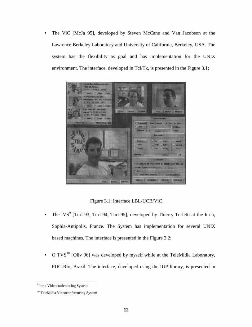
• The ViC [McJa 95], developed by Steven McCane and Van Jacobson at the
Lawrence Berkeley Laboratory and University of California, Berkeley, USA. The
system has the flexibility as goal and has implementation for the UNIX
environment. The interface, developed in Tcl/Tk, is presented in the Figure 3.1;
Figure 3.1: Interface LBL-UCB/ViC
• The IVS9 [Turl 93, Turl 94, Turl 95], developed by Thierry Turletti at the Inria,
Sophia-Antipolis, France. The System has implementation for several UNIX
based machines. The interface is presented in the Figure 3.2;
• O TVS10 [Oliv 96] was developed by myself while at the TeleMídia Laboratory,
PUC-Rio, Brazil. The interface, developed using the IUP library, is presented in
9 Inria Videoconferencing System
10 TeleMídia Videoconferencing System

13
the Figure 3.3. The IUP library was also developed at PUC-Rio [Levy 93] and
provides an easy toolkit for interface definition.
Figure 3.2: Interface Inria/IVS
All this systems have a very modest framerate, and proved that the H.261 is not adequate
to be used on the Internet, where just low bitrate is available. In the last few years, the
ITU-T began studies on Low bitrate real time video transmission. This recommendation
is still in development stage. Its first draft was published in May 2nd, 1996.
All remarks that follows in this report are based on the May 2nd, 1996 ITU-T H.263 Draft
Recommendation and 1993 ITU-T H.261 Recommendation. In the next sections, the
structure of the H.263 bitstream is presented as well as a set of characteristics of this
recommendation. Most of the time, characteristics of the H.261 recommendation are also
presented in comparison.

14
Figure 3.3: Interface PUC-Rio/TVS
3.2. H.263 x H.261
The H.263 structure is very similar to the H.261. Figure 3.4 shows the block diagram for
the H.263 codec [H.263] and the Figure 3.5 shows the same block diagram, for the H.261
codec.
As can be seen, the main difference is the presence of a transmission coder/decoder in the
H.261 recommendation, otherwise, the block diagram is the same.

15
Coding control
Sourcecoder
Sourcedecoder
Video multiplexcoder
Video multiplexdecoder
Transmissionbuffer
Receivingbuffer
Codedbitstream
Videosignal
a) Video coder
b) Video decoder
External control
Figure 3.4: Block Diagram of the H.263 Video Codec
Concerning the picture format, anticipate in Figure 2.3, the original H.261
recommendation adopts just two picture formats, namely CIF and QCIF. The H.263
adopts three more picture formats, 4CIF (defined first in the IVS prototype, see the big
image in Figure 3.2), 16CIF and SubQCIF (SQCIF), the aspect ratio is 4:3 as in a TV.
Coding Control
Source Video MultiplexCoder
TransmissionBuffer
TransmissionCoder
ReceivingDecoder
ReceivingBuffer
Video MultiplexDecoder
SourceDecoder
Coder
External Control
Videosignal
Codedbit stream
Video Coder
Video Decoder
Figure 3.5: Block Diagram for H.261 Video Codec

16
Picture Format number of pixelsfor luminance (dx)
number of lines forluminance (dy)
number of pixels forchrominance (dx/2)
number of lines forchrominance (dy/2)
sub-QCIF 128 96 64 48
QCIF 176 144 88 72
CIF 352 288 176 144
4CIF 704 576 352 288
16CIF 1408 1152 704 576
Figure 3.6: H.263 picture format resolutions
Some extensions proposed to the H.261 codec have included the SQCIF as an QCIF
image, filling the remaining space with black, since the SQCIF is smaller than the QCIF.
ΧΧΧΧΧΧΧΧ
ΧΧΧΧΧΧΧΧ
ΧΧΧΧΧΧΧΧ
ΧΧΧΧΧΧΧΧ
ΧΧΧΧΧΧΧΧ
ΧΧΧΧΧΧΧΧ
ΧΧΧΧΧΧΧΧ
ΧΧΧΧΧΧΧΧ
ΧΧΧΧΧΧΧΧ
ΧΧΧΧΧΧΧΧ
ΧΧΧΧΧΧΧΧ
ΧΧΧΧΧΧΧΧ
ΧΧΧΧΧΧΧΧ
ΧΧΧΧΧΧΧΧ
ΧΧΧΧΧΧΧΧ
ΧΧΧΧΧΧΧΧ
ΧΧΧΧΧΧΧΧ
ΧΧΧΧΧΧΧΧ
ΧΧΧΧΧΧΧΧ
ΧΧΧΧΧΧΧΧ
ΧΧΧΧΧΧΧΧ
ΧΧΧΧΧΧΧΧ
ΧΧΧΧΧΧΧΧ
ΧΧΧΧΧΧΧΧ
ΧΧΧΧΧΧΧΧ
ΧΧΧΧΧΧΧΧ
ΧΧΧΧΧΧΧΧ
ΧΧΧΧΧΧΧΧ
ΧΧΧΧΧΧΧΧ
ΧΧΧΧΧΧΧΧ
ΧΧΧΧΧΧΧΧ
ΧΧΧΧΧΧΧΧ
Χ - Luminância - Crominância
Figure 3.7: Luminance and Chrominance positions inside a Macroblock

17
Figure 3.6 presents a comparison among the five H.263 picture resolution standards,
presenting the their three components: Y, CB and CR, respectively luminance and two
different color components, whose values are in accordance with the ITU-R (previously
CCIR) Recommendation 601. The source coder operates on non-interlaced pictures at a
30,000/1001 (≈29.97) rate. The position of the luminance and chrominance samples is
presented in the Figure 3.7. The Chrominance components are sub sampled at the 4:1:1
rate, as shown in Figure 3.7, where for each four luminance components there is one
chrominance component; however, there are two of them.
Both the H.261 and H.263 codecs have a four-layer hierarchical structure. The layers are
Picture layer, Group of Blocks layer, Macroblock layer, and Block layer. Figure 3.9
shows the structure of each of these layers for the H.263 stream, Section 3.3 defines each
of those components.
A block is an 8x8 matrix of coefficients while a macroblock is a set of 6 blocks, being 4
luminance blocks and two chrominance blocks, as shown in Figure 3.8. A Group of
Blocks (GOB) is a Macroblock, and then comes the Picture when each picture is divided
into groups of blocks (GOBs).
Y
C
C
R
B
1 2
3 4
5
6
Figure 3.8: Arrangement of Blocks in a Macroblock

18
Figure 3.9: Syntax Diagram for Video Bitstream

19
H.263 defines that a group of blocks (GOB) comprises of k*16 lines, depending on the
picture format (k = 1 for sub-QCIF, QCIF and CIF; k = 2 for 4CIF; k = 4 for 16CIF). The
number of GOBs per picture is 6 for sub-QCIF, 9 for QCIF, and 18 for CIF, 4CIF and
16CIF. The GOB numbering is done by use of vertical scan of the GOBs, starting with
the upper GOB (number 0) and ending with the lower GOB.
3.3. The H.263 Source Coder
The source coder is shown in generalized form in Figure 3.10. The main elements are
prediction, block transformation and quantization.
CC
T Q
Q
T
P
p
t
qz
q
v
Videoin
Tovideomultiplexcoder
TQP
CCptqzqv
–1
–1
TransformQuantizerPicture Memory with motion compensated variable delay
Coding controlFlag for INTRA/INTERFlag for transmitted or notQuantizer indicationQuantizing index for transform coefficientsMotion vector
Figure 3.10: Source Coder

20
3.3.1. Prediction
The prediction is inter-picture and may be augmented by motion compensation. The
coding mode in which prediction is applied is called INTER; the coding mode is called
INTRA if no prediction is applied. The INTRA coding mode can be signaled at the
picture level ( INTRA for I-pictures or INTER for P-pictures) or at the macroblock level
in P-pictures. In the optional PB-frames mode B-pictures are always coded in INTER
mode. The B-pictures are partly predicted bidirectionally. The Bidirectional Prediction is
optional.
3.3.2. Motion compensation
The decoder will accept one vector per macroblock or if the optional Advanced
Prediction mode is used one or four vectors per macroblock. If the PB-frames mode is
used, one additional delta vector can be transmitted per macroblock for adaptation of the
motion vectors for prediction of the B-macroblock.
Both horizontal and vertical components of the motion vectors have integer or half
integer values. In the default prediction mode, these values are restricted to the range
[-16,15.5] (this is also valid for the forward and backward motion vector components for
B-pictures). In the Unrestricted Motion Vector mode however, the maximum range for
vector components is [-31.5,31.5], with the restriction that only values that are within a
range of [-16,15.5] around the predictor for each motion vector component can be
reached if the predictor is in the range [-15.5,16]. If the predictor is outside [-15.5,16], all
values within the range [-31.5,31.5] with the same sign as the predictor plus the zero
value can be reached.

21
A positive value of the horizontal or vertical component of the motion vector signifies
that the prediction is formed from pixels in the referenced picture which are spatially to
the right or below the pixels being predicted.
3.3.3. Quantization
The number of quantizers is 1 for the first coefficient of INTRA blocks and 31 for all
other coefficients. Within a macroblock the same quantizer is used for all coefficients
except the first one of INTRA blocks. The decision levels are not defined. The first
coefficient of INTRA blocks is nominally the transform DC value uniformly quantized
with a step size of 8. Each of the other 31 quantizers use equally spaced reconstruction
levels with a central dead-zone around zero and with a step size of an even value in the
range 2 to 62.
3.3.4. Zig-Zag Scan
The coder takes advantage of the spatial redundancy through the use of DCT followed by
a zig-zag scan given in Figure 3.11. The coefficient 1 is the DC coefficient.
1 2 6 7 15 16 28 29
3 5 8 14 17 27 30 43
4 9 13 18 26 31 42 44
10 12 19 25 32 41 45 54
11 20 24 33 40 46 53 55
21 23 34 39 47 52 56 61
22 35 38 48 51 57 60 62
36 37 49 50 58 59 63 64
Figure 3.11: Zig-Zag Scanning

22
3.4. Semantic and Syntax
3.4.1. Picture Layer
Data for each picture consists of a picture header followed by data for Group of Blocks,
eventually followed by an end-of-sequence code and stuffing bits. The structure was
shown in Figure 3.9 and is also presented in Figure 3.12. According to the
recommendation, the PSBI is only present if indicated by CPM. TRB and DBQUANT are
only present if PTYPE indicates ‘PB-frame’. Combinations of PSPARE and PEI may not
be present. EOS may not be present, while ESTUF may be present only if EOS is present.
PSC TR PTYPE PQUANT CPM PSBI TRB DBQUANT PEI PSPARE PEI Group of Blocks ESTUF EOS PSTUF
Figure 3.12: Picture Layer Structure
• Picture Start Code (PSC) (22 bits): PSC is a word of 22 bits. Its value is 0000 0000
0000 0000 1 00000. All picture start codes must be byte aligned. This is achieved by
inserting PSTUF before the start code such that the first bit of the start code is the first
(most significant) bit of a byte.
• Temporal Reference (TR) (8 bits): An 8-bit number which can have 256 possible
values. It is formed by incrementing its value in the previously transmitted picture
header by one plus the number of non-transmitted pictures (at 29.97 Hz) since the
previously transmitted one.
• Type Information (PTYPE) (13 bits): Information about the complete picture as
shown in Figure 3.13.

23
Bit Function1 Always “1”, in order to avoid start code emulation.2 Always “0”, for distinction with H.261,3 Split screen indicator, “0” off, “1” on,4 Document camera indicator, “0” off, “1” on,5 Freeze Picture Release, “0” off, “1” on,
6-8 Source Format, “000” forbidden, “001” sub-QCIF, “010” QCIF, “011” CIF, “100”4CIF, “101” 16CIF, “110” reserved, “111” reserved,
9 Picture Coding Type, “0” INTRA (I-picture), “1” INTER (P-picture),10 Optional Unrestricted Motion Vector mode, “0” off, “1” on,11 Optional Syntax-based Arithmetic Coding mode, “0” off, “1” on,12 Optional Advanced Prediction mode, “0” off, “1” on,13 Optional PB-frames mode, “0” normal I- or P-picture, “1” PB-frame.
Figure 3.13: PTYTE bits
Split screen indicator is a signal that indicates that the upper and lower half of the
decoded picture could be displayed side by side. This bit has no direct effect on the
encoding or decoding of the picture.
Freeze Picture Release is a signal from an encoder which responds to a request for
packet retransmission or fast update request and allows a decoder to exit from its
freeze picture mode and display decoded picture in the normal manner.
If bit 6-8 indicate a different source format than in the previous picture header, the
current picture has to be an I-picture.
Bit 10-13 refer to optional modes that are only used after negotiation between encoder
and decoder. If bit 9 is set to “0”, bit 13 has to be set to “0” as well.
• Quantizer Information (PQUANT) (5 bits): A fixed length codeword of 5 bits which
indicates the quantizer QUANT to be used for the picture until updated by any

24
subsequent GQUANT or DQUANT. The codewords are the natural binary
representations of the values of QUANT which, being half the step sizes, range from 1
to 31.
• Continuous Presence Multipoint (CPM) (1 bit): A codeword of 1 bit that signals the
use of the optional Continuous Presence Multipoint mode (CPM); “0” is off, “1” is on.
• Picture Sub Bitstream Indicator (PSBI) (2 bits): A fixed length codeword of 2 bits
that is only present if Continuous Presence Multipoint mode is indicated by CPM. The
codewords are the natural binary representation of the sub-bitstream number for the
picture header and all following information until the next Picture or GOB start code.
• Temporal Reference for B-pictures (TRB) (3 bits): TRB is present if PTYPE
indicates ‘PB-frame’ and indicates the number of non-transmitted pictures (at 29.97
Hz) since the last P- or I-picture and before the B-picture. The codeword is the natural
binary representation of the number of non-transmitted pictures plus one. The
maximum number of non-transmitted pictures is 6.
• Quantization information for B-pictures (DBQUANT ) (2 bits): DBQUANT is
present if PTYPE indicates ‘PB-frame’. In the decoding process a quantization
parameter QUANT is obtained for each macroblock. With PB-frames QUANT is used
for the P-block, while for the B-block a different quantization parameter BQUANT is
used. QUANT ranges from 1 to 31. DBQUANT indicates the relation between
QUANT and BQUANT as defined in Figure 3.14. In this table, “/” means division by

25
truncation. BQUANT ranges from 1 to 31; if the value for BQUANT resulting from
Figure 3.14 is greater than 31, it is clipped to 31.
DBQUANT BQUANT00 (5xQUANT)/401 (6xQUANT)/410 (7xQUANT)/411 (8xQUANT)/4
Figure 3.14: DBQUANT codes and relation between QUANT and BQUANT
• Extra Insertion Information (PEI) (1 bit): A bit which when set to "1" signals the
presence of the following optional data field.
• Spare Information (PSPARE) (0/8/16 . . . bits): If PEI is set to "1", then 9 bits follow
consisting of 8 bits of data (PSPARE) and then another PEI bit to indicate if a further 9
bits follow and so on. Encoders mustn’t insert PSPARE until specified by the ITU.
Decoders have to be designed to discard PSPARE if PEI is set to 1. This is defined to
allow the ITU to specify future backward compatible additions in PSPARE. If
PSPARE is followed by PEI=0, PSPARE=xx000000 is prohibited in order to avoid
start code emulation (x=don’t care, so 4 out of 256 values are prohibited).
• Stuffing (ESTUF) (Variable length): A codeword of variable length consisting of less
than 8 zero-bits. Encoders may insert this codeword directly before an EOS codeword.
If ESTUF is present, the last bit of ESTUF shall be the last (least significant) bit of a
byte, so that the start of the EOS codeword is byte aligned. Decoders have to be
designed to discard ESTUF.

26
• End Of Sequence (EOS) (22 bits): A codeword of 22 bits. Its value is 0000 0000
0000 0000 1 11111. It is up to the encoder to insert this codeword or not. EOS may be
byte aligned. This can be achieved by inserting ESTUF before the start code such that
the first bit of the start code is the first (most significant) bit of a byte.
• Stuffing (PSTUF) (Variable length): A codeword of variable length consisting of less
than 8 zero-bits. Encoders have to insert this codeword for byte alignment of the next
PSC. The last bit of PSTUF have to be the last (least significant) bit of a byte, so that
the video bitstream including PSTUF is a multiple of 8 bits from the first bit in the
H.263 bitstream. Decoders have to be designed to discard PSTUF.
3.4.2. Group of Block Layer
Data for each Group of Blocks (GOB) consists of a GOB header followed by data for
macroblocks. The structure is shown in Figure 3.9 as well as Figure 3.15. Each GOB
contains one or more rows of macroblocks. According to the H.263 recommendation,
GSTUF may be present when GBSC is present. GN, GFID and GQUANT are present
when GBSC is present. GSBI is present when Continuous Presence Multipoint mode is
on, as indicated in the Picture header.
GSTUF GBSC GN GSBI GFID GQUANT Macroblock Data
Figure 3.15: Structure of GOB layer
• Stuffing (GSTUF) (Variable length): A codeword of variable length consisting of less
than 8 zero-bits. Encoders may insert this codeword directly before an GBSC
codeword. If GSTUF is present, the last bit of GSTUF has to be the last (least

27
significant) bit of a byte, so that the start of the GBSC codeword is byte aligned.
Decoders shall be designed to discard GSTUF.
• Group of Block Start Code (GBSC) (17 bits): A word of 17 bits. Its value is 0000
0000 0000 0000 1. GOB start codes may be byte aligned. This can be achieved by
inserting GSTUF before the start code such that the first bit of the start code is the first
(most significant) bit of a byte.
• Group Number (GN) (5 bits): A fixed length codeword of 5 bits. The bits are the
binary representation of the number of the Group of Blocks. For the GOB with number
0, the GOB header including GSTUF, GBSC, GN, GSBI, GFID and GQUANT is
empty; group number 0 is used in the PSC. Group number 31 is used in the EOS and
the values from 18 to 30 are reserved for future use by the ITU.
• GOB Sub Bitstream Indicator (GSBI) (2 bits): A fixed length codeword of 2 bits
that is only present if Continuous Presence Multipoint mode is indicated by CPM. The
codewords are the natural binary representation of the sub-bitstream number for the
GOB header and all following information until the next Picture or GOB start code.
• GOB Frame ID (GFID ) (2 bits): A fixed length codeword of 2 bits. GFID has to have
the same value in every GOB header of a given picture. Moreover, if PTYPE as
indicated in a picture header is the same as for the previous transmitted picture, GFID
has to have the same value as in that previous picture. However, if PTYPE in a certain

28
picture header differs from the PTYPE in the previous transmitted picture header, the
value for GFID in that picture shall differ from the value in the previous picture.
• Quantizer Information (GQUANT ) (5 bits): A fixed length codeword of 5 bits
which indicates the quantizer QUANT to be used for the remaining part of the picture
until updated by any subsequent GQUANT or DQUANT. The codewords are the
natural binary representations of the values of QUANT which, being half the step
sizes, range from 1 to 31.
3.4.3. Macroblock Layer
Data for each macroblock consists of a macroblock header followed by data for blocks.
The structure is shown in Figure 3.9 as well as Figure 3.16. According to the H.263
recommendation, COD is only present in pictures for which PTYPE indicates ‘INTER’,
for each macroblock in these pictures. MCBPC is present when indicated by COD or
when PTYPE indicates ‘INTRA’. MODB is present for MB-type 0-4 if PTYPE indicates
‘PB-frame’. CBPY, DQUANT, MVD and MVD2-4 are present when indicated by
MCBPC. CBPB and MVDB are only present if indicated by MODB. Block Data is
present when indicated by MCBPC and CBPY. MVD2-4 are only present in Advanced
Prediction mode. MODB, CBPB and MVDB are only present in PB-frames mode.
COD MCBPC MODB CBPB CBPY DQUANT MVD MVD2 MVD3 MVD4 MVDB
Block Data
Figure 3.16: Structure of macroblock layer

29
• Coded macroblock indication (COD) (1 bit): A bit which when set to "0" signals
that the macroblock is coded. If set to "1", no further information is transmitted for this
macroblock; in that case the decoder shall treat the macroblock as an INTER
macroblock with motion vector for the whole block equal to zero and with no
coefficient data. COD is only present in pictures for which PTYPE indicates ‘INTER’,
for each macroblock in these pictures.
• Macroblock type & Coded block pattern for chrominance (MCBPC) (Variable
length): A variable length codeword giving information about the macroblock type and
the coded block pattern for chrominance. MCBPC is always included in coded
macroblocks.
• Macroblock mode for B-blocks (MODB ) (Variable length): MODB is present for
MB-type 0-4 if PTYPE indicates ‘PB-frame’ and is a variable length codeword
indicating whether CBPB is present (indicates that B-coefficients are transmitted for
this macroblock) and/or MVDB is present.
• Coded block pattern for B-blocks (CBPB) (6 bits): CBPB is only present in PB-
frames mode if indicated by MODB. CBPBN = 1 if any coefficient is present for B-
block N, else 0, for each bit CBPBN in the coded block pattern.
• Coded block pattern for luminance (CBPY) (Variable length): Variable length
codeword giving a pattern number signifying those Y blocks in the macroblock for
which at least one non-INTRADC transform coefficient is transmitted. CBPYN = 1 if

30
any non-INTRADC coefficient is present for block N, else 0, for each bit CBPYN in
the coded block pattern. Block numbering is given in FIGURE 5/H.263, the utmost left
bit of CBPY corresponding with block number 1.
• Quantizer Information (DQUANT ) (2 bits): A two bit code to define change in
QUANT. QUANT ranges from 1 to 31; if the value for QUANT after adding the
differential value is less than 1 or greater than 31, it is clipped to 1 and 31 respectively.
• Motion vector data (MVD ) (Variable length): MVD is included for all INTER
macroblocks (in PB-frames mode also for INTRA macroblocks) and consists of a
variable length codeword for the horizontal component followed by a variable length
codeword for the vertical component.
• Motion vector data (MVD 2-4) (Variable length): The three codewords MVD2-4 are
included if indicated by PTYPE and by MCBPC, and consist each of a variable length
codeword for the horizontal component followed by a variable length codeword for the
vertical component of each vector. MVD2-4 are only present when in Advanced
Prediction mode.
• Motion vector data for B-macroblock (MVDB ) (Variable length): MVDB is only
present in PB-frames mode if indicated by MODB and consists of a variable length
codeword for the horizontal component followed by a variable length codeword for the
vertical component of each vector.

31
3.4.4. Block Layer
If not in PB-frames mode, a macroblock comprises four luminance blocks and one of
each of the two colour difference blocks as shown in Figure 3.7. The structure of the
block layer is shown in Figure 3.17.
INTRADC TCOEF
Figure 3.17: Structure of block layer
In PB-frames mode, a macroblock comprises twelve blocks. First the data for the six P-
blocks is transmitted as in the default H.263 mode, then the data for the six B-blocks.
INTRADC is present for every P-block of the macroblock if MCBPC indicates MB type
3 or 4. INTRADC is not present for B-blocks. TCOEF is present for P-blocks if indicated
by MCBPC or CBPY; TCOEF is present for B-blocks if indicated by CBPB.
Index FLC Reconstruction level
into inverse transform
0 0000 0001 (1) 8
1 0000 0010 (2) 16
2 0000 0011 (3) 24
. . . .
. . . .
126 0111 1111 (127) 1016
127 1111 1111 (255) 1024
128 1000 0001 (129) 1032
. . . .
. . . .
252 1111 1101 (253) 2024
253 1111 1110 (254) 2032
Figure 3.18: Reconstruction levels for INTRA-mode DC coefficient
32
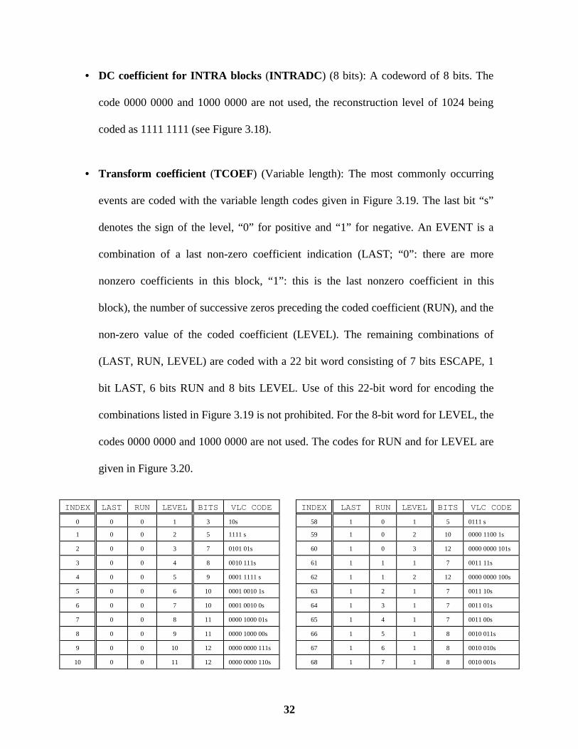
• DC coefficient for INTRA blocks (INTRADC ) (8 bits): A codeword of 8 bits. The
code 0000 0000 and 1000 0000 are not used, the reconstruction level of 1024 being
coded as 1111 1111 (see Figure 3.18).
• Transform coefficient (TCOEF) (Variable length): The most commonly occurring
events are coded with the variable length codes given in Figure 3.19. The last bit “s”
denotes the sign of the level, “0” for positive and “1” for negative. An EVENT is a
combination of a last non-zero coefficient indication (LAST; “0”: there are more
nonzero coefficients in this block, “1”: this is the last nonzero coefficient in this
block), the number of successive zeros preceding the coded coefficient (RUN), and the
non-zero value of the coded coefficient (LEVEL). The remaining combinations of
(LAST, RUN, LEVEL) are coded with a 22 bit word consisting of 7 bits ESCAPE, 1
bit LAST, 6 bits RUN and 8 bits LEVEL. Use of this 22-bit word for encoding the
combinations listed in Figure 3.19 is not prohibited. For the 8-bit word for LEVEL, the
codes 0000 0000 and 1000 0000 are not used. The codes for RUN and for LEVEL are
given in Figure 3.20.
INDEX LAST RUN LEVEL BITS VLC CODE INDEX LAST RUN LEVEL BITS VLC CODE
0 0 0 1 3 10s 58 1 0 1 5 0111 s
1 0 0 2 5 1111 s 59 1 0 2 10 0000 1100 1s
2 0 0 3 7 0101 01s 60 1 0 3 12 0000 0000 101s
3 0 0 4 8 0010 111s 61 1 1 1 7 0011 11s
4 0 0 5 9 0001 1111 s 62 1 1 2 12 0000 0000 100s
5 0 0 6 10 0001 0010 1s 63 1 2 1 7 0011 10s
6 0 0 7 10 0001 0010 0s 64 1 3 1 7 0011 01s
7 0 0 8 11 0000 1000 01s 65 1 4 1 7 0011 00s
8 0 0 9 11 0000 1000 00s 66 1 5 1 8 0010 011s
9 0 0 10 12 0000 0000 111s 67 1 6 1 8 0010 010s
10 0 0 11 12 0000 0000 110s 68 1 7 1 8 0010 001s

33
INDEX LAST RUN LEVEL BITS VLC CODE INDEX LAST RUN LEVEL BITS VLC CODE
11 0 0 12 12 0000 0100 000s 69 1 8 1 8 0010 000s
12 0 1 1 4 110s 70 1 9 1 9 0001 1010 s
13 0 1 2 7 0101 00s 71 1 10 1 9 0001 1001 s
14 0 1 3 9 0001 1110 s 72 1 11 1 9 0001 1000 s
15 0 1 4 11 0000 0011 11s 73 1 12 1 9 0001 0111 s
16 0 1 5 12 0000 0100 001s 74 1 13 1 9 0001 0110 s
17 0 1 6 13 0000 0101 0000s 75 1 14 1 9 0001 0101 s
18 0 2 1 5 1110 s 76 1 15 1 9 0001 0100 s
19 0 2 2 9 0001 1101 s 77 1 16 1 9 0001 0011 s
20 0 2 3 11 0000 0011 10s 78 1 17 1 10 0000 1100 0s
21 0 2 4 13 0000 0101 0001s 79 1 18 1 10 0000 1011 1s
22 0 3 1 6 0110 1s 80 1 19 1 10 0000 1011 0s
23 0 3 2 10 0001 0001 1s 81 1 20 1 10 0000 1010 1s
24 0 3 3 11 0000 0011 01s 82 1 21 1 10 0000 1010 0s
25 0 4 1 6 0110 0s 83 1 22 1 10 0000 1001 1s
26 0 4 2 10 0001 0001 0s 84 1 23 1 10 0000 1001 0s
27 0 4 3 13 0000 0101 0010s 85 1 24 1 10 0000 1000 1s
28 0 5 1 6 0101 1s 86 1 25 1 11 0000 0001 11s
29 0 5 2 11 0000 0011 00s 87 1 26 1 11 0000 0001 10s
30 0 5 3 13 0000 0101 0011s 88 1 27 1 11 0000 0001 01s
31 0 6 1 7 0100 11s 89 1 28 1 11 0000 0001 00s
32 0 6 2 11 0000 0010 11s 90 1 29 1 12 0000 0100 100s
33 0 6 3 13 0000 0101 0100s 91 1 30 1 12 0000 0100 101s
34 0 7 1 7 0100 10s 92 1 31 1 12 0000 0100 110s
35 0 7 2 11 0000 0010 10s 93 1 32 1 12 0000 0100 111s
36 0 8 1 7 0100 01s 94 1 33 1 13 0000 0101 1000s
37 0 8 2 11 0000 0010 01s 95 1 34 1 13 0000 0101 1001s
38 0 9 1 7 0100 00s 96 1 35 1 13 0000 0101 1010s
39 0 9 2 11 0000 0010 00s 97 1 36 1 13 0000 0101 1011s
40 0 10 1 8 0010 110s 98 1 37 1 13 0000 0101 1100s
41 0 10 2 13 0000 0101 0101s 99 1 38 1 13 0000 0101 1101s
42 0 11 1 8 0010 101s 100 1 39 1 13 0000 0101 1110s
43 0 12 1 8 0010 100s 101 1 40 1 13 0000 0101 1111s
44 0 13 1 9 0001 1100 s 102 ESCAPE 7 0000 011
45 0 14 1 9 0001 1011 s
46 0 15 1 10 0001 0000 1s
47 0 16 1 10 0001 0000 0s
48 0 17 1 10 0000 1111 1s
49 0 18 1 10 0000 1111 0s
50 0 19 1 10 0000 1110 1s
51 0 20 1 10 0000 1110 0s
52 0 21 1 10 0000 1101 1s

34
INDEX LAST RUN LEVEL BITS VLC CODE
53 0 22 1 10 0000 1101 0s
54 0 23 1 12 0000 0100 010s
55 0 24 1 12 0000 0100 011s
56 0 25 1 13 0000 0101 0110s
57 0 26 1 13 0000 0101 0111s
Figure 3.19: VLC table for TCOEF
Index Run Code Index Level Code
0 0 000 000 - -128 FORBIDDEN
1 1 000 001 0 -127 1000 0001
2 2 000 010 . . .
. . . 125 -2 1111 1110
. . . 126 -1 1111 1111
63 63 111 111 - 0 FORBIDDEN
127 1 0000 0001
128 2 0000 0010
. . .
253 127 0111 1111
Figure 3.20: FLC table for RUNS and LEVELS

35
Chapter IV
4. The Java Paradigm
In 1990, Sun Microsystems began studies on development of a platform independent
object oriented language. Some few years ago, a first version of this language was
available. The language was named Java. After this two released updates, versions 1.0.2
and the newest 1.1. are mostly widely used at this moment.
4.1. Java’s Architecture
Java’s Architecture, shown in Figure 4.1, consists of a two step procedure, to run a
program: First, a programmer writes a Java source code and compiles it. The Java
compiler (javac ) creates an intermediate code, called Byte Code. The Byte Code is an
intermediate code, not a specific code for a specific machine; it runs on an abstract
machine called the Java Virtual Machine (java ). That’s why the code can run in any Java
enabled machine. It is sufficient for a particular machine to have a Java Virtual Machine
(JVM) implementation to run any Java code. In the second step, the user submits a
previously compiled Java Byte Code to the JVM, in order to run the application. The
JVM originally works as an interpreter. All this process is summarized in the Figure 4.2.

36
JavaJavaCodeCode
JavaJavaCompilerCompiler BytecodeBytecode JavaJava
InterpreterInterpreterExecuteExecuteProgramProgram
runtimeruntime
++
JVMJVM
Figure 4.1: The Java Architecture
There are two different kinds of Java programs. The first is called a system, and works
like a standard program such as a C code, the only difference is that the system runs over
the JVM, through an interpretation procedure; the second Java program type is called
Applet, which consist of a program that runs inside a Java Enabled Browser, such as
Netscape, Microsoft Internet Explorer, or Sun’s HotJava. A Java Enabled Browser
contains an implementation of a JVM, which makes possible the execution of Java Byte
Code. An Applet has a set of restrictions that were imposed for security reasons. For
instance, an Applet is not allowed to handle any hardware device, e.g. as Hard Drive. So,
it is not possible for somebody to write a harmful Applet which would delete all files on a
Hard Disk.
import java.awt.*import java.awt.iimport java.appleimport java.net.*;import java.io.*;import java.lang.
public class prog{ Image oImage boolean bSho
program.java program.class
javacjavac browserbrowserjavajava Execution
Figure 4.2: The steps required to run a program written in Java

37
The main feature of Java is the portability which makes easily possible the maintenance
of a program that is supposed to run on several different machines.
4.2. Approaches for Applications for the Web
Until the creation of Java, when an application was available on the Internet, the user had
to find the application, download the right version for his/her machine and operating
system, if it is available, install the program, and finally, run it. Problem may occur if the
program is not available for a determined machine, for instance, a version for OS2 is
usually not available on the Internet. Now with Java, and particularly Applets, a user just
has to find the application he/she needs, click in the application’s link and the application
will run. Automatically the application will be downloaded, installed, submitted to the
JVM, and then executed. After the execution, the program will be automatically deleted.
In the next time the user runs the program, the actual version will pass through the same
process. Here we found another advantage in using Java Applets. If the programmer
updates something in the Applet, for example including a new option in it, the user will
run this new version without any necessary action from the user point of view in order to
update his/her program, which is required for the conventional program paradigm.
4.3. Java Advantages and Disadvantages
As advantages, it is possible to quote the following:
• The program is platform independent. It can even run on non PC devices, such as
Web-TV, Cellular phone PDA’s, Network Devices.

38
• It is easy to update and to maintain a program as commented before.
• The Byte Code is extremely small, hence, is downloaded quickly. The code is small
because it is not needed to link the code with libraries, since the JVM has a set of run
time libraries with everything that is needed to run a program (see Figure 4.1).
• The language itself provides support for network communication through TCP/IP.
On the other hand, it is possible to enumerate the following disadvantages:
• It runs slower than a traditional program, due to the interpreting before running step;
however, Just in Time compiling (JIT) can increase speed. That’s why a Java Applet
runs faster on Windows than on Solaris, for example, because the first uses the Just In
Time compiling technique in its browsers, while the second doesn’t do it.
• Security restrictions, such as no file manipulation, can make hard some
implementations; however it is possible to write a Java system program to run as a
server and exchange information with the Applet. The Java program is allowed to
handle devices such as Hard Disk, etc. Due to the security restrictions an Applet can
only exchange information with a server written for that Applet.
39
Chapter V
5. Java H.263 implementation
The goal of this project was to write an H.263 decoder in Java, in order to take advantage
of the portability of the language. Now, the code can be converted into an Applet, since it
does not access any device and can receive the video stream from a network connection.
In this chapter, the implementation is presented as well as some limitations of Java in bit
operations.
5.1. Codec Architecture
The Codec was planned with the architecture presented in the Figure 5.1 in mind. In some
place, a user has a video camera that provides video to a video capture board, this video
grabber provides the video stream to a small program, written in C due to performance
matter, and this program receives the video stream and codes it into an H.263 video
stream. Then, this video stream is provided to a Java Application, that works as a server
as defined in the previous chapter. This Java Server, called Java Video Server just sends
the H.263 video stream to an Applet that has required it through a network connection.
On the other side of the network a user that is running the Java Decoder Applet (JDA),
will see the video sent by the server in a window that the JDA opens to display the video.

40
Java was not developed for efficient bit handling. The performance of this decoder is
heavily damaged because of it; however, the new versions of Java will introduce some
new features that should improve the performance.
Video Destination
Java AppletH.263 Decoder
Video Source
C H.263Video Coder
JavaVideo Server
Video Capture BoardVideo Capture Board
NetworkNetwork
Figure 5.1: Java Video Codec Architecture
In the actual decoder, a method to convert from a Byte into an Integer and from an Integer
back to Byte was required (Byte = 8 bits signaled integer; Integer 32 bits signaled
integer). The problem shown bellow, required the implementation of the following
methods:
From Byte to Integer:
• 11001100 = -52 ⇒ 11...111001100 = -52 instead of expected 00…011001100.
From Integer to Byte:
00…0010000000 = 128 ⇒ 00000000 = 0 instead of the expected 10000000.

41
int Byte2Int(byte bValue){
int iReturn = bValue;
return iReturn&0xff;}
byte Int2Byte(int iValue){
byte bReturn=0;
iValue &= 0xff;
if(iValue==128){
bReturn = -128;return bReturn;
}return (byte) iValue;
}
Bellow, the dither method that convert the Y, Cr, Cb components used by the ITU-T
H.263 recommendation into the RGB components required to create a Java Image is
presented. Note that for each component, the above Byte2Int and Int2Byte methods have
to be performed several times, which degrades the performance substantially.
void Color32DitherImage(byte src[][], int out[]){
byte lum[] = src[0];byte cb[] = src[1];byte cr[] = src[2];int cols, iCR=0, iCB=0, iLUM=0;int rows;
int L, CR, CB;int row1, row2;int lum2;int x, y;int cr_r;int cr_g;int cb_g;int cb_b;int cols_2;
cols = coded_picture_width;rows = coded_picture_height;cols_2= cols/2;row1 = 0;row2 = cols_2 + cols_2;lum2 = cols_2 + cols_2;
for(y=0; y<rows; y+=2){
for(x=0; x<cols_2; x++){
int R, G, B;

42
CR = Byte2Int(cr[iCR++]);CB = Byte2Int(cb[iCB++]);cr_r = Cr_r_tab[CR];cr_g = Cr_g_tab[CR];cb_g = Cb_g_tab[CB];cb_b = Cb_b_tab[CB];
L = L_tab[Byte2Int(lum[iLUM++])];
R = (L + cr_r);G = (L + cr_g + cb_g);B = (L + cb_b);
out[row1++] = (0xff<<24 | R<<16 | G<<8 | B );
L = L_tab[Byte2Int(lum[iLUM++])];
R = (L + cr_r);G = (L + cr_g + cb_g);B = (L + cb_b);
out[row1++] = (0xff<<24 | R<<16 | G<<8 | B );
L = L_tab [Byte2Int(lum[lum2++])];R = (L + cr_r);G = (L + cr_g + cb_g);B = (L + cb_b);
out[row2++] = (0xff<<24 | R<<16 | G<<8 | B);
L = L_tab [Byte2Int(lum[lum2++])];R = (L + cr_r);G = (L + cr_g + cb_g);B = (L + cb_b);
out[row2++] = (0xff<<24 | R<<16 | G<<8 | B);}iLUM += cols_2 + cols_2;lum2 += cols_2 + cols_2;row1 += cols_2 + cols_2;row2 += cols_2 + cols_2;
}}
Both methods Int2Byte and Byte2Int are also largely used during the decoding of the
video stream, where each byte has to be converted into an integer, that works as a buffer
with 32 bits inside.
// return next n bits (right adjusted) without advancingint ShowBits(int piNumber){
int iValue;int iByte=0;int iCalc;
if(iInputCounter<piNumber)FillBuffer();

43
iValue = (96 - iInputCounter)>>>3;
iByte=(Byte2Int(viInputBuffer[iValue])<<24)|(Byte2Int(viInputBuffer[iValue+1])<<16)|(Byte2Int(viInputBuffer[iValue+2])<<8)|Byte2Int(viInputBuffer[iValue+3]);
iCalc = ((iInputCounter-1) & 7) + 25;
return (iByte>>>(iCalc-piNumber)) & viMask[piNumber];}
Figure 5.2: H.263 × H.261
The H.263 Codec has a better performance than the H.261 Codec discussed in Chapter 2
and 3. Figure 5.2 shows a comparison between them. The performance of the decoder
written in Java is very fair, since the frame rate of just 2 frames/sec was reached. The
frame rate should be improved when the next release of Java becomes available. In future
44
a new structure called Multimedia Framework will be included which should improve the
bit operation capabilities.
The decoder has a little bit more than 3860 lines, just for comparison, this document up to
this point has 1930 lines, exactly one half of the decoder source code.

45
Chapter VI
6. Conclusion
The implementation of an H.263 Java Decoder as well as an architecture for exchange of
video transmission through a network was presented in this document. Due to the fact
that the decoder was written in Java, it is possible to receive the video on any machine,
such as Windows95, MacOS or Unix stations. This decoder is going to be used in the
JETS project (Java Enabled TeleColaboration System) at Multimedia Communications
Research Laboratory to create a videoconferencing environment over Java Enabled
Browsers, such as Netscape, Microsoft Internet Explorer, Sun’s HotJava, etc.
The Decoder has shown to be robust; however the frame rate needs a substantial
improvement.
6.1. Further Recommendation and Future Work
• Rewrite some parts of the Decoder Applet in order to improve the performance on not
so powerful CPU’s.
• Include the Coder/Decoder architecture in the JETS project, in order to improve the
telelearning environment (http://www.mcrlab.uottawa.ca/jets).

46
• Adapt the Coder to be used as video source, the video capture board itself, as well as
complete the communication between Coder/Decoder.
• Include some of the H.263 optional features that were not implemented in this first
prototype.
• To adapt the Java Video Server to use the RTP11 [IETF 97]for efficient multicast
transmission.
11 Real Time Protocol

47
References
[ChHa 96] Cherriman, P.; Hanzo, L. - “Robust H.263 Video Transmission overMobile Channels in Interference Limited Environments” - 1st IEEE Wireless VideoCommunication Workshop, UK, September, 1996.
[Draft G.723] International Telecommunication Union, TelecommunicationStandardization Sector - “Dual Rate Speech Coder for Multimedia CommunicationsTransmitting at 5.3 & 6.3 Kbit/s” - Draft ITU-T Recommendation G.723, September1995.
[Draft H.263] International Telecommunication Union, TelecommunicationStandardization Sector - “Line Transmission of non-Telephone Signals - Video Codingfor Low Bitrate Communications” - Draft ITU-T Recommendation H.263, July 1995.
[Draft H.223] International Telecommunication Union, TelecommunicationStandardization Sector - “Line Transmission of non-Telephone Signals - MultiplexingProtocol for Low Bitrate Multimedia Communication” - Final Draft ITU-TRecommendation H.223, to be published in next.
[Draft H.324] International Telecommunication Union, TelecommunicationStandardization Sector - “Line Transmission of non-Telephone Signals - Terminal forLow Bitrate Multimedia Communication” - Draft ITU-T Recommendation H.324,September 1995.
[Draft H.245] International Telecommunication Union, TelecommunicationStandardization Sector - “Line Transmission of non-Telephone Signals - MultimediaControl Protocol” - Draft ITU-T Recommendation H.324, September 1995.
[F.730] International Telecommunication Union, TelecommunicationStandardization Sector - "Telematic, Data Transmission, ISDN Broadband, Universal,Personal Communications and Teleconference Services: Operation and Quality of Service- Videoconference Service - General" - ITU-T Recommendation F.730, August 1992
[Fluc 95] Fluckiger, F. - “Understanding Networked Multimedia - Applicationsand Technology” - Prentice Hall, 1995
[G.711] Comité Consultatif International de Télégraphique et Téléphonic - “PulseCode Modulation (PCM) of Voice Frequencies” - CCITT Recommendation G.711, fromCCITT Blue Book.
[G.722] Comité Consultatif International de Télégraphique et Téléphonic - “7kHzAudio-coding Within 64 kbits/s” CCITT Recommendation G.722, from CCITT BlueBook.
[G.725] International Telecommunication Union, TelecommunicationStandardization Sector - "General Aspects of Digital Transmission Systems; TerminalEquipment - System Aspects for the Use of the 7 kHz Audio Codec Within 64 kbit/s" -ITU-T Recommendation G.725, 1988.

48
[G.728] International Telecommunication Union, TelecommunicationStandardization Sector - "General Aspects of Digital Transmission Systems; TerminalEquipment - Coding of Speech at 16 kbit/s Using Low-Delay Code Excited LinearPrediction" - ITU-T Recommendation G.728, September 1992.
[H.200] International Telecommunication Union, TelecommunicationStandardization Sector - "Line Transmission of non-Telephone Signals - Framework forRecommendations for Audiovisual Services" - ITU-T Recommendation H.200, March1993.
[H.221] International Telecommunication Union, TelecommunicationStandardization Sector - "Line Transmission of non-Telephone Signals - Frame Structurefor a 64 to 1920 kbit/s Channel in Audiovisual Teleservices" - ITU-T RecommendationH.221, March 1993.
[H.230] International Telecommunication Union, TelecommunicationStandardization Sector - "Line Transmission of non-Telephone Signals - FrameSynchronous Control and Indication Signals for Audiovisual Systems" - ITU-TRecommendation H.230, March 1993.
[H.242] International Telecommunication Union, TelecommunicationStandardization Sector - "Line Transmission of non-Telephone Signals - System forEstablishing Communication Between Audiovisual Terminals Using Digital Channels upto 2 Mbit/s" - ITU-T Recommendation H.242, March 1993.
[H.261] International Telecommunication Union, TelecommunicationStandardization Sector - "Line Transmission of non-Telephone Signals - Video Codec forAudiovisual Services at p×64 Kbit/s" - ITU-T Recommendation H.261, March 1993.
[H.320] International Telecommunication Union, TelecommunicationStandardization Sector - "Line Transmission of non-Telephone Signals - Narrow-BandVisual Telephone Systems and Terminal Equipment" - ITU-T Recommendation H.320,March 1993.
[IETF 97] Internet Engineering Task Force Draft - “RTP Payload Format forH.263 Video Stream” - March 1997.
[Levy 93] Levy, C.H. - “IUP/LED: Uma Ferramenta Portátil de Interface com oUsuário” - Master Dissertation - Computer Science Department / PUC-Rio, 1993.
[Liou 91] Liou, M. - "Overview of the p×64 kbit/s video coding standard" -Communications of the ACM, No. 4, April de 1991.
[McJa 95] McCane, S.; Jacobson, V. - “ViC: A Flexible Framework for PacketVideo” - ACM Multimedia 95, San Francisco, CA, November 1995.
[MHEG 95] MHEG - Information Technology - “Coded Representation ofMultimedia and Hypermedia Information Objects - Part 1: Base Notation”, CommitteeDraft ISO/IEC, 1995.
[OlSo 96] Oliveira, J.C. de; Soares, L.F.G. - “TVS - Um Sistema deVideoconferência com Documentos Compartilhados - Uma Visão Geral” - WoSH’96 - II

49
Workshop on Hypermedia Systems, XIV SBRC - Brazilian Symposium on Computernetworks, May 1996.
[Oliv 96] Oliveira, J. C. de - “TVS: Um Sistema de Videoconferencia” - MasterDissertation, Computer Science Department, PUC-Rio, August de 1996.
[Schn 95] Schneier B. - “Applied Cryptography” - 2nd Edition - John Willey,November 1995.
[SoMB 88] Soares, L.F.G.; Martins, S. de L.; Bastos, T.L.P. - "LAN Based RealTime Audio-Graphics Conferencing System, General Overview" - CCR066 TechnicalReport Rio Scientific Center-IBM Brazil, November 1988.
[STCN 92] Soares, L.F.G.; Tucherman, L.; Casanova, M.A.; Nunes, P.R.R.L. -“Fundamentos de Sistemas Multimídia” - VIII Computer Science School, Gramado,Brazil, 1992.
[Turl 93] Turletti, T. - "A H.261 Software Codec for Videoconferencing over theInternet" - INRIA Research Report, # 1834, January 1993.
[Turl 94] Turletti, T. - “The INRIA Videoconferencing System (IVS)” -ConneXions, Volume VIII, # 10, October 1994
[Turl 95] Turletti, T. - "Contrôle de Transmission pour Logiciel deVidéoconférence sur l'Internet" - Doctorate Thesis, L'Universite de Nice - SophiaAntipolis, April 1995.
[Wall 91] Wallace, G.K. - “The JPEG Still Picture Compression Standard” -Digital Equipment Corporation (Submitted for publication on December 1991 to “IEEETransactions on Consumer Electronics”), 1991.