a look at system i integrated dasd configuration and ... a look at system i integrated dasd...
TRANSCRIPT
ibm.com/redbooks Redpaper
Front cover
A Look at System i Integrated DASD Configuration and Performance under i5/OS
Jim CookSue Baker
Brian PodrowChris Place
Integrated disk configuration from a performance view
Lots of disk performance considerations and tips
Featuring the large read/write controllers

International Technical Support Organization
A Look at System i Integrated DASD Configuration and Performance under i5/OS
April 2008
REDP-3919-00
© Copyright International Business Machines Corporation 2008. All rights reserved.Note to U.S. Government Users Restricted Rights -- Use, duplication or disclosure restricted by GSA ADP ScheduleContract with IBM Corp.
First Edition (April 2008)
This edition applies to Version 5, Release 3, Modification 0 and Version 5, Release 4, Modification 0 of i5/OS.
This document created or updated on April 8, 2008.
Note: Before using this information and the product it supports, read the information in “Notices” on page v.
Contents
Notices . . . . . . . . . . . . . . . . . . . . . . . . . . . . . . . . . . . . . . . . . . . . . . . . . . . . . . . . . . . . . . . . . .vTrademarks . . . . . . . . . . . . . . . . . . . . . . . . . . . . . . . . . . . . . . . . . . . . . . . . . . . . . . . . . . . . . . vi
Preface . . . . . . . . . . . . . . . . . . . . . . . . . . . . . . . . . . . . . . . . . . . . . . . . . . . . . . . . . . . . . . . . . viiThe team that wrote this IBM Redpaper . . . . . . . . . . . . . . . . . . . . . . . . . . . . . . . . . . . . . . . viiiBecome a published author . . . . . . . . . . . . . . . . . . . . . . . . . . . . . . . . . . . . . . . . . . . . . . . . . . ixComments welcome. . . . . . . . . . . . . . . . . . . . . . . . . . . . . . . . . . . . . . . . . . . . . . . . . . . . . . . . ix
Chapter 1. The importance of disk subsystems to system performance . . . . . . . . . . . 11.1 Understanding the key components of overall system performance. . . . . . . . . . . . . . . . 21.2 Configuration factors affecting disk subsystem performance . . . . . . . . . . . . . . . . . . . . . 4
1.2.1 Key observations affecting disk performance . . . . . . . . . . . . . . . . . . . . . . . . . . . . . 5
Chapter 2. Understanding disk performance . . . . . . . . . . . . . . . . . . . . . . . . . . . . . . . . . . 72.1 Some definitions . . . . . . . . . . . . . . . . . . . . . . . . . . . . . . . . . . . . . . . . . . . . . . . . . . . . . . . 82.2 Disk drive considerations . . . . . . . . . . . . . . . . . . . . . . . . . . . . . . . . . . . . . . . . . . . . . . . 122.3 Disk controller considerations . . . . . . . . . . . . . . . . . . . . . . . . . . . . . . . . . . . . . . . . . . . . 142.4 Other considerations affecting disk sizing, performance, and availability . . . . . . . . . . . 15
2.4.1 Overall disk sizing considerations. . . . . . . . . . . . . . . . . . . . . . . . . . . . . . . . . . . . . 152.4.2 Mirroring compared to RAID-5 or RAID-6 . . . . . . . . . . . . . . . . . . . . . . . . . . . . . . . 192.4.3 The importance of auxiliary write cache . . . . . . . . . . . . . . . . . . . . . . . . . . . . . . . . 202.4.4 Other disk subsystem functions affecting performance . . . . . . . . . . . . . . . . . . . . 21
Chapter 3. Large read and write cache disk controllers and enclosures . . . . . . . . . . 233.1 New disk controllers used with existing (#5094/5294) disk towers . . . . . . . . . . . . . . . . 24
3.1.1 Auxiliary write cache features for new #5738/5777 IOAs and older#2757/2780 IOAs . . . . . . . . . . . . . . . . . . . . . . . . . . . . . . . . . . . . . . . . . . . . . . . . . 24
3.1.2 Positioning the February 2007 disk controllers used in #5094/5294 towers . . . . . 253.2 TotalStorage EXP24 disk enclosure features and capabilities . . . . . . . . . . . . . . . . . . . 263.3 Disk controllers that support the EXP24 disk drawer and tower . . . . . . . . . . . . . . . . . . 293.4 Positioning the new disk controllers and EXP24 disk enclosures . . . . . . . . . . . . . . . . . 32
Chapter 4. Planning and installation considerations for large cache disk controllers 354.1 Minimum code levels. . . . . . . . . . . . . . . . . . . . . . . . . . . . . . . . . . . . . . . . . . . . . . . . . . . 364.2 Feature code to CCIN cross reference . . . . . . . . . . . . . . . . . . . . . . . . . . . . . . . . . . . . . 384.3 Card placement rules . . . . . . . . . . . . . . . . . . . . . . . . . . . . . . . . . . . . . . . . . . . . . . . . . . 39
4.3.1 5094, 5294, 9094, 9194, and 8294 PCI-X expansion units . . . . . . . . . . . . . . . . . 394.3.2 5096, 5296 PCI-X expansion units . . . . . . . . . . . . . . . . . . . . . . . . . . . . . . . . . . . . 424.3.3 5790 PCI-X expansion units . . . . . . . . . . . . . . . . . . . . . . . . . . . . . . . . . . . . . . . . . 434.3.4 5088, 0588 PCI-X expansion units . . . . . . . . . . . . . . . . . . . . . . . . . . . . . . . . . . . . 434.3.5 5095, 0595 PCI-X expansion units . . . . . . . . . . . . . . . . . . . . . . . . . . . . . . . . . . . . 454.3.6 520 POWER5 system units. . . . . . . . . . . . . . . . . . . . . . . . . . . . . . . . . . . . . . . . . . 474.3.7 520 POWER5+ system units . . . . . . . . . . . . . . . . . . . . . . . . . . . . . . . . . . . . . . . . 474.3.8 550 POWER5 system units. . . . . . . . . . . . . . . . . . . . . . . . . . . . . . . . . . . . . . . . . . 484.3.9 550 POWER5+ system units . . . . . . . . . . . . . . . . . . . . . . . . . . . . . . . . . . . . . . . . 484.3.10 570 POWER5 system units. . . . . . . . . . . . . . . . . . . . . . . . . . . . . . . . . . . . . . . . . 494.3.11 570 POWER5+ system units . . . . . . . . . . . . . . . . . . . . . . . . . . . . . . . . . . . . . . . 494.3.12 5074, 5079, and 9094 expansion units . . . . . . . . . . . . . . . . . . . . . . . . . . . . . . . . 50
© Copyright IBM Corp. 2008. All rights reserved. iii
4.4 Parity set planning. . . . . . . . . . . . . . . . . . . . . . . . . . . . . . . . . . . . . . . . . . . . . . . . . . . . . 514.4.1 RAID-5 . . . . . . . . . . . . . . . . . . . . . . . . . . . . . . . . . . . . . . . . . . . . . . . . . . . . . . . . . 514.4.2 RAID-6 . . . . . . . . . . . . . . . . . . . . . . . . . . . . . . . . . . . . . . . . . . . . . . . . . . . . . . . . . 52
4.5 EXP24 disk enclosure and CCIN 571F IOA . . . . . . . . . . . . . . . . . . . . . . . . . . . . . . . . . 524.5.1 EXP24 disk enclosure front and rear views . . . . . . . . . . . . . . . . . . . . . . . . . . . . . 544.5.2 Feature 5741/5742 Disk Slot Enabler placement and cabling recommendations. 554.5.3 Load source drive considerations in #5786/#5787 . . . . . . . . . . . . . . . . . . . . . . . . 56
Chapter 5. Performance considerations . . . . . . . . . . . . . . . . . . . . . . . . . . . . . . . . . . . . . 595.1 Review of performance test results . . . . . . . . . . . . . . . . . . . . . . . . . . . . . . . . . . . . . . . . 60
5.1.1 2780 versus new IOAs . . . . . . . . . . . . . . . . . . . . . . . . . . . . . . . . . . . . . . . . . . . . . 615.1.2 RAID-6 versus RAID-5 . . . . . . . . . . . . . . . . . . . . . . . . . . . . . . . . . . . . . . . . . . . . . 615.1.3 RAID-5 versus mirroring . . . . . . . . . . . . . . . . . . . . . . . . . . . . . . . . . . . . . . . . . . . . 62
5.2 Disk controller I/O performance guidelines . . . . . . . . . . . . . . . . . . . . . . . . . . . . . . . . . . 63
Appendix A. System i integrated disk capabilities that require a SAN on other systems . . . . . . . . . . . . . . . . . . . . . . . . . . . . . . . . . . . . . . . . 65
SAN and native System i capabilities. . . . . . . . . . . . . . . . . . . . . . . . . . . . . . . . . . . . . . . . . . 66Conclusion . . . . . . . . . . . . . . . . . . . . . . . . . . . . . . . . . . . . . . . . . . . . . . . . . . . . . . . . . . . . . . 68
Appendix B. Understanding disk write cache . . . . . . . . . . . . . . . . . . . . . . . . . . . . . . . . 69
Appendix C. Understanding RAID-5, RAID-6, and associated performance considerations . . . . . . . . . . . . . . . . . . . . . . . . . . . . . . . . . . . . . . . . . . . . . . 73
A brief history of RAID . . . . . . . . . . . . . . . . . . . . . . . . . . . . . . . . . . . . . . . . . . . . . . . . . . . . . 74The various RAID levels. . . . . . . . . . . . . . . . . . . . . . . . . . . . . . . . . . . . . . . . . . . . . . . . . . . . 74
Appendix D. Mirroring. . . . . . . . . . . . . . . . . . . . . . . . . . . . . . . . . . . . . . . . . . . . . . . . . . . . 85Mirroring overview . . . . . . . . . . . . . . . . . . . . . . . . . . . . . . . . . . . . . . . . . . . . . . . . . . . . . . . . 86Disk activity and performance during normal mirrored operations . . . . . . . . . . . . . . . . . . . . 86Mirroring performance during disk outage operations . . . . . . . . . . . . . . . . . . . . . . . . . . . . . 88Mirroring performance during disk drive rebuild operations . . . . . . . . . . . . . . . . . . . . . . . . . 89Recovery from a controller failure with mirrored disk controllers . . . . . . . . . . . . . . . . . . . . . 90Using double capacity disks in a mirrored environment . . . . . . . . . . . . . . . . . . . . . . . . . . . . 91Some conclusions about mirroring implementations on the System i . . . . . . . . . . . . . . . . . 92
Appendix E. Additional examples of situations using mixed capacity disk drives . . 95Example 1 . . . . . . . . . . . . . . . . . . . . . . . . . . . . . . . . . . . . . . . . . . . . . . . . . . . . . . . . . . . . . . 96Example 2a . . . . . . . . . . . . . . . . . . . . . . . . . . . . . . . . . . . . . . . . . . . . . . . . . . . . . . . . . . . . . 96Example 2b . . . . . . . . . . . . . . . . . . . . . . . . . . . . . . . . . . . . . . . . . . . . . . . . . . . . . . . . . . . . . 97
Appendix F. References to articles on future disk technologies and replacements . 99
Appendix G. A real-world approach to sizing disks for adequate performance . . . . 101
Related publications . . . . . . . . . . . . . . . . . . . . . . . . . . . . . . . . . . . . . . . . . . . . . . . . . . . . 111IBM Redbooks Publications . . . . . . . . . . . . . . . . . . . . . . . . . . . . . . . . . . . . . . . . . . . . . . . . 111Online resources . . . . . . . . . . . . . . . . . . . . . . . . . . . . . . . . . . . . . . . . . . . . . . . . . . . . . . . . 111How to get IBM Redbooks Publications . . . . . . . . . . . . . . . . . . . . . . . . . . . . . . . . . . . . . . . 111Help from IBM . . . . . . . . . . . . . . . . . . . . . . . . . . . . . . . . . . . . . . . . . . . . . . . . . . . . . . . . . . 111
iv A Look at System i Integrated DASD Configuration and Performance under i5/OS
Notices
This information was developed for products and services offered in the U.S.A.
IBM may not offer the products, services, or features discussed in this document in other countries. Consult your local IBM representative for information on the products and services currently available in your area. Any reference to an IBM product, program, or service is not intended to state or imply that only that IBM product, program, or service may be used. Any functionally equivalent product, program, or service that does not infringe any IBM intellectual property right may be used instead. However, it is the user's responsibility to evaluate and verify the operation of any non-IBM product, program, or service.
IBM may have patents or pending patent applications covering subject matter described in this document. The furnishing of this document does not give you any license to these patents. You can send license inquiries, in writing, to: IBM Director of Licensing, IBM Corporation, North Castle Drive, Armonk, NY 10504-1785 U.S.A.
The following paragraph does not apply to the United Kingdom or any other country where such provisions are inconsistent with local law: INTERNATIONAL BUSINESS MACHINES CORPORATION PROVIDES THIS PUBLICATION “AS IS” WITHOUT WARRANTY OF ANY KIND, EITHER EXPRESS OR IMPLIED, INCLUDING, BUT NOT LIMITED TO, THE IMPLIED WARRANTIES OF NON-INFRINGEMENT, MERCHANTABILITY OR FITNESS FOR A PARTICULAR PURPOSE. Some states do not allow disclaimer of express or implied warranties in certain transactions, therefore, this statement may not apply to you.
This information could include technical inaccuracies or typographical errors. Changes are periodically made to the information herein; these changes will be incorporated in new editions of the publication. IBM may make improvements and/or changes in the product(s) and/or the program(s) described in this publication at any time without notice.
Any references in this information to non-IBM Web sites are provided for convenience only and do not in any manner serve as an endorsement of those Web sites. The materials at those Web sites are not part of the materials for this IBM product and use of those Web sites is at your own risk.
IBM may use or distribute any of the information you supply in any way it believes appropriate without incurring any obligation to you.
Information concerning non-IBM products was obtained from the suppliers of those products, their published announcements or other publicly available sources. IBM has not tested those products and cannot confirm the accuracy of performance, compatibility or any other claims related to non-IBM products. Questions on the capabilities of non-IBM products should be addressed to the suppliers of those products.
This information contains examples of data and reports used in daily business operations. To illustrate them as completely as possible, the examples include the names of individuals, companies, brands, and products. All of these names are fictitious and any similarity to the names and addresses used by an actual business enterprise is entirely coincidental.
COPYRIGHT LICENSE:
This information contains sample application programs in source language, which illustrate programming techniques on various operating platforms. You may copy, modify, and distribute these sample programs in any form without payment to IBM, for the purposes of developing, using, marketing or distributing application programs conforming to the application programming interface for the operating platform for which the sample programs are written. These examples have not been thoroughly tested under all conditions. IBM, therefore, cannot guarantee or imply reliability, serviceability, or function of these programs.
© Copyright IBM Corp. 2008. All rights reserved. v
Trademarks
The following terms are trademarks of the International Business Machines Corporation in the United States, other countries, or both:
Redbooks (logo) ®iSeries®i5/OS®AIX®AS/400®DS6000™DS8000™
IBM®PowerPC®POWER™POWER5™POWER5+™POWER6™Redbooks®
System i™System x™System/38™TotalStorage®1350™
The following terms are trademarks of other companies:
Java, Ultra, and all Java-based trademarks are trademarks of Sun Microsystems, Inc. in the United States, other countries, or both.
UNIX is a registered trademark of The Open Group in the United States and other countries.
Linux is a trademark of Linus Torvalds in the United States, other countries, or both.
Other company, product, or service names may be trademarks or service marks of others.
vi A Look at System i Integrated DASD Configuration and Performance under i5/OS
Preface
This IBM® Redpaper publication summarizes integrated DASD configuration, DASD protection capabilities, and DASD performance through the disk controller hardware announced through 2007 and supported by i5/OS® V5R3 and V5R4. For the hardware features that we cover in this paper, the information should also apply to later releases.
We feature the large read and write cache disk controllers announced during 1Q 2007 in this paper and include the following information:
� Specifications of the latest disk controller hardware (including physical placement of the disk controller cards within supporting hardware enclosures)
� RAID-5, RAID-6, and mirrored protection considerations
� Positioning the available DASD hardware and protection features
� Positioning the DASD component contribution to application performance
� General guidelines for DASD hardware choices based upon estimated disk I/O operation rates with the different protection methods
� Analyzing DASD performance statistics gathered by i5/OS to see how the environment correlates with the general guidelines
The content of this paper is intended to be used by customers, IBM employees, IBM Business Partners, and others who desire or who need an understanding of disk subsystems in the System i™ product line.
Content encompasses both System i integrated disk hardware that was available before 2007 as well as integrated disk hardware announced during 2007. Disk related I/O hardware announced after March 2008 and externally attached disk hardware through a Storage Area Network configuration are beyond the scope of this book.
It is important to note that System i and i5/OS disk management has some capabilities that are not found commonly under other hardware platforms and operating systems. One example is in the disk mirroring area. System i mirroring support includes not only mirroring at the individual disk level, but also:
� At the disk adapter (controller) level (protects against an adapter failure with both mirrored disks attached
� At the I/O bus level (protects against multiple adapter failures with the mirrored disks attached)
Note: This publication does not specifically address new disk adapters or any new i5/OS release announced after December 2007.
© Copyright IBM Corp. 2008. All rights reserved. vii
The team that wrote this IBM Redpaper
This IBM Redpaper was produced by a team of specialists from around the world working at the International Technical Support Organization (ITSO), Rochester Center.
Jim Cook is a Senior Software Engineer Project Leader at the ITSO, Rochester Center. He leads teams that produce IBM System i announcement presentation sets that are maintained on the System i technical support Web sites and presents at ITSO iSeries® Forums internationally. Jim also produces IBM Redbooks® Publications about various System i and i5/OS-related topics.
Sue Baker is a Certified Consulting IT Specialist in the U.S. She has spent over 25 years working with IBM S/3x, AS/400®, iSeries, and System i products. Sue has a long history of and continues to work with customers in the challenging arena of managing the operating environment, specifically focused on implementing and integrating various technologies and systems management disciplines that lead to a highly available, highly performing, resilient System i infrastructure. Sue is a speaker at the System i Technical Conference, various user groups meetings, and System i availability planning seminars around the country. High availability (HA/DR), storage (integrated and SAN attached), save/restore, performance, and POWER5™ processor technology are a just a sampling of the topics that she addresses in her presentations and customer engagements.
Brian Podrow joined IBM over 30 years ago after receiving his MBA from UCLA (with a dual major of Computer and Information Systems and Finance). He has worked with Rochester-based products almost that entire time and disk considerations for over 20 years. He has been an SE (authoring various software packages for IBM), a Sales representative, and has held multiple staff assignments. Brian is currently one of the System i Product Managers for the Americas. He is a frequent speaker at customer and IBM Internal and Partner training events and teleconferences. He is probably best known within IBM and the Business Partner community as the author of numerous papers and tools that help train the sales force on new announcements and that allow them to better understand how to configure systems optimally (for price and performance).
Chris Place is an IT Specialist in the U.S. He works in the Americas System i Technical Sales Support organization in Rochester Minnesota. He has worked at IBM for 13 years. Chris has over five years of experience analyzing various aspects of System i performance. Chris' areas of expertise include LIC, LPAR performance, and DASD performance. He has written extensively on LPAR performance. He works with customers directly in the areas of I/O hardware performance. He presents at various user groups and the IBM System i Technical Conference.
Thanks to the following people for their contributions to this project:
Clark AndersonIBM STG Enterprise Systems Development, Server Storage I/O subsystem performance
Lee ClevelandIBM STG System i and p Internal Storage TCEM
Eric HessIBM Americas System i Advanced Technical Sales Support
James HermesIBM STG, Enterprise Systems Development Technical Lead - I/O Storage Adapter Integration
viii A Look at System i Integrated DASD Configuration and Performance under i5/OS
Become a published author
Join us for a two- to six-week residency program! Help write an IBM Redbooks Publication dealing with specific products or solutions, while getting hands-on experience with leading-edge technologies. You will have the opportunity to team with IBM technical professionals, Business Partners, and Clients.
Your efforts will help increase product acceptance and customer satisfaction. As a bonus, you will develop a network of contacts in IBM development labs, and increase your productivity and marketability.
Find out more about the residency program, browse the residency index, and apply online at:
ibm.com/redbooks/residencies.html
Comments welcome
Your comments are important to us!
We want our IBM Redbooks Publications to be as helpful as possible. Send us your comments about this paper or other IBM Redbooks Publications in one of the following ways:
� Use the online Contact us review Redbooks form found at:
ibm.com/redbooks
� Send your comments in an e-mail to:
� Mail your comments to:
IBM Corporation, International Technical Support OrganizationDept. HYTD Mail Station P0992455 South RoadPoughkeepsie, NY 12601-5400
Preface ix

x A Look at System i Integrated DASD Configuration and Performance under i5/OS
Chapter 1. The importance of disk subsystems to system performance
This chapter provides an overview of the importance of disk subsystems to system performance.
1
© Copyright IBM Corp. 2008. All rights reserved. 1
1.1 Understanding the key components of overall system performance
In general, the components of performance can be listed simply as:
� Processor (CPU)
� Memory
� Disk
� Communications link, transmitting any data (requests) into the systems and responses from the system (application) to the requester
� Wait conditions
Overall system performance is affected by many factors within each of these components. These include:
� Processor speed and system architecture, including how the System i uses main memory to provide disk cache functionality
� The amount of memory on the system and, to a lesser extent its speed, due to L1, L2, and L3 processor caches
� The speed of the disk subsystem, the disk drive controllers, and the disk drives themselves.
In compute-intensive environments, the speed of the processor, the processor architecture (including caches), and the speeds of transfers between memory and the processor are of paramount importance. The POWER5 and POWER6™ Simultaneous Multithreading (SMT) is designed to minimize the wait time at the processor level when there is a large enough set of threads (tasks) ready to use a processor, even on systems with multiple processors. SMT is focused on, ensuring each individual processor is concurrently executing multiple tasks at the same time when the “then currently running task” goes into any kind of wait status, even at the level of waiting for data to be paged into main storage (memory).
In database-intensive environments, the speed of the disks and the disk subsystems contribute greatly to overall performance. Frankly, all processors wait at the same speed, and if a processor cannot perform work due to data not being available as rapidly as might be needed, that program (actually task within the program) ends up waiting.
Fortunately, when this happens, the system usually does a task switch and continues processing other tasks. However, especially on small systems or on systems running single stream batch jobs, there can come a point where there are not enough tasks for the system to switch between, and overall system performance can suffer while the system waits for a disk access to complete prior to being able to issue the next disk request.
This paper focuses on the disk component of performance. Therefore, we assume other performance component areas, such as processor utilization, are not overriding the disk performance considerations that we address. For example, if you had a workload environment where the processor capacity was a bottleneck, you would not really know until you corrected that issue whether there is disk performance issues. That is, the working environment is such that the disk component is spending much of its time just waiting for I/O requests to be issued by the system (applications).
Assuming no processor capacity issue, at the program level, if a disk drive is busy when data is requested, a wait must occur while the current disk access completes, before the request can be fulfilled. During this time, the system attempts to switch to other tasks. This optimizes
2 A Look at System i Integrated DASD Configuration and Performance under i5/OS
overall system performance, but can delay completion of a specific job. These disk busy waits can be particularly significant when running single stream batch workloads, where the system might not have other tasks to switch to.
i5/OS uses the following techniques to minimize disk activity and, therefore, wait times:
� The approaches start with the self-caching capabilities of the system memory. For each i5/OS LPAR, if data is already in memory, any other program with appropriate security, can use the data without a physical disk request being needed. This technique is further enhanced by using i5/OS options such as expert cache (which is usually recommended). We discuss this self-caching capability further in the read cache topic of Appendix A, “System i integrated disk capabilities that require a SAN on other systems” on page 65.
� If the program needs to access the disk physically for a read, different events occur, depending on whether the system is using disk mirroring. If mirroring is active, the system determines which of the mirrored disks (and controller if that level of mirroring is in use) has lower disk activity and sends the read request to that drive (and controller).
� When the request gets to the disk controller, the processing is, in part, determined by the physical controller in use. There is a read cache in the controllers, which was announced in February 2007 (for example, the #5738 PCI-X Ultra320 SCSI Disk Controller with 1.5 GB Write / 1.6 GB Read caches or the #5781 PCI-X EXP24 Controller - 1.5 GB Write / 1.6 GB Read caches), as well as in the #2780/5580/5590 controller family).
Due to the self-cache functionality of the system memory, many of the disk requests that occur on other systems are never issued. Therefore, this cache is only used after other easier caches (inside main memory) are exhausted. In many ways, it can be thought of as a secondary cache to the main memory. Nevertheless, it can provide additional benefits in some applications and environments that have a level of predictable reads. The value of this cache is application dependent and is most effective when the data in close proximity is read periodically, but not frequently enough to be held in main memory. It is also useful when a separate relatively small memory size i5/OS partition is used to provide virtualized disk capabilities to Linux®, AIX®, or System x™ or Blade Server operating systems (using iSCSI connections).
� Most System i disk attachment controllers are very high-speed and 15 k rpm disks are the current standard. The drives themselves also contain read-ahead buffers that can be useful during sequential processing. The drives continue to read data into buffers after the specific read request has been satisfied. The assumption being that one of the next several disk requests might be sequential in nature and could therefore be satisfied without waiting on disk arm movement or rotational delays.
All of these approaches help to minimize the time for disk reads. From a disk write perspective, large write caches are used. These are true write caches that combine and eliminate physical disk writes to the disks. They are not just write buffers that are unfortunately too often incorrectly referred to as write caches. (We present details about write cache capabilities in Appendix B, “Understanding disk write cache” on page 69.) By using the write cache, most disk write completes are signaled to the system in a fraction of a millisecond. They are then destaged to the disks asynchronously. With the size of the write caches in today’s high performance disk controllers, write cache overruns (where the cache becomes so full that some records must be physically written to disk before an incoming write can be accepted) are becoming an increasingly rare occurrence.
Today, write cache overruns usually only occur when a disk subsystem has been configured improperly (usually with too few disk arms) and the disks are so busy that data in the cache
Note: We discuss write cache overruns more fully in Appendix B, “Understanding disk write cache” on page 69.
Chapter 1. The importance of disk subsystems to system performance 3
cannot be sent to disk as fast as new data is being sent to the cache. The large capacity caches help eliminate this concern.
Minimizing the number of required physical reads and writes is important to disk and, therefore, system performance. However, the following other factors also come into play:
� i5/OS automatically spreads all databases and other objects among all the disks in each Auxiliary Storage Pool (ASP or in the partition or system if ASPs are not being used). This helps prevent disk hot spots where one disk drive is heavily utilized (and therefore can start to bottleneck) while other disks might be used relatively lightly.
This native System i capability exceeds the data spreading approaches used by storage subsystem devices connected using Storage Area Networks (SANs), which are often the only way to provide the spreading function to other platforms. See Appendix A, “System i integrated disk capabilities that require a SAN on other systems” on page 65 for additional information about native i5/OS SAN-like capabilities.
� Insufficient main memory can result in more paging and other disk-oriented tasks than might otherwise be required. Furthermore, a lack of memory can lead to less efficiency in self-caching capabilities of the system. That is why various performance parameters need to be set with regard to processor speed and memory size, and why more memory can sometimes help eliminate disk performance issues.
It is important to recognize that disk performance is not linear. Performance can be excellent for a wide level of disk activity and then a little more activity can start to cause major slowdowns.
This situation can be likened to a major highway with multiple lanes. When there are not many cars on the road, everything runs at the speed limit. As more cars start travel the road, there is more activity. More cars move past a given point each second. There is less of a gap between the cars, but they are still running at the speed limit. This situation continues until there are so many cars that the distance between the cars begins to shrink and gridlock begins as drivers get closer and closer together and are forced to reduce their speed. The speed difference caused by only 5% more cars can be significant.
The same situation occurs with disk drives, disk controllers, and other parts of the subsystem. This bottleneck phenomenon—running smoothly until a specific level of activity is reached, followed by severe slowdowns—is an important consideration in configuring disk subsystems. You need to ensure that activity levels remain below the knee of the curve, where disk performance is rapid and relatively uniform.
1.2 Configuration factors affecting disk subsystem performance
In February 2007, IBM announced new disk controllers that allow better utilization of disk drives or more disks to be attached to a single disk controller. IBM also announced are new disk enclosures that support more disk drives both within each enclosure and within a single rack. As with any disk configuration, when using these new features, it is important to properly size the configuration to provide optimal use of available resources.
In this section, we discuss some general configuration guidelines for disk subsystem performance.
4 A Look at System i Integrated DASD Configuration and Performance under i5/OS
1.2.1 Key observations affecting disk performance
Key observations that affect disk performance include:
� For optimal performance, there must be sufficient disk drives and controllers to meet the workload requirements. Too few disk drives or controllers can result in performance bottlenecks.
� Today’s high speed controllers and disks can usually perform more disk requests each second than older components. If you order the same number of disks or controllers as were required in the past, these controllers might “over-configure” the system with more disk subsystem performance capability than what the system will actually request. This, of course, assumes that the original configuration met the requirements and that the new system is going to be running with similar volumes.
� The increased speed of today’s high speed disk controllers allow 15 k rpm disk drives to perform more accesses each second than the previous generation of disk controllers. Therefore, larger capacity disks are sometimes a more cost-effective solution. Also, double capacity disks are usually recommended for mirrored environments.
� Planning is needed before mixing different controllers or different capacity disk drives in the same Auxiliary Storage Pool (ASP). With mixed capacity disks, the larger drives will usually need to perform two to four times as many accesses each second as the smaller drives. This can cause performance imbalances or can provide cost savings when higher speed controllers are used with the larger capacity disks and lower speed controllers with the smaller capacity drives.
This paper addresses these considerations and others to help ensure that the new features are used in the most effective manner. In the process, we discuss concepts and capabilities that are applicable to all disk subsystems.
Chapter 1. The importance of disk subsystems to system performance 5

6 A Look at System i Integrated DASD Configuration and Performance under i5/OS
Chapter 2. Understanding disk performance
Before examining the specifics of the new disk controllers and enclosures, it is worthwhile to spend some time understanding the factors that contribute to disk performance. In this chapter, we examine some definitions surrounding disk performance, after which we discuss disk drive and disk controller considerations.
We also discuss other considerations that affect disk sizing, performance, and availability, including:
� Overall disk sizing considerations, including mixing different size disk drives or different speed disk controllers
� Mirroring versus RAID-5 or RAID-6
� Auxiliary Write Cache capabilities
We discuss several of these topics in greater detail in the appendixes later in this paper.
2
© Copyright IBM Corp. 2008. All rights reserved. 7
2.1 Some definitions
This section defines a few terms that we use throughout this paper. Understanding them provides a basis for the more detailed discussions. We feel that this understanding is important because an incorrect assumption can lead to invalid expectation levels. Understand that our definitions might not match your initial assumptions (for example, the term performance itself can be viewed in more than one way).
Rather than present the terms in alphabetical order, we start with some of the simpler definitions and concepts and build on them as we define other terms.
� Direct Access Storage Device (DASD)
System i and its predecessors use this term to refer to disk drives. In this paper, we make every effort to use the term disk rather than DASD, because DASD seems to be primarily an IBM term and might not be familiar to all readers. We do, however, feel that the term deserves mention from a historical (and futures) perspective.
Historically, when IBM provided the first (and to date only) implementation of Single Level Storage in the industry, on the predecessor of the System i and AS/400, the System/38™, there were various technologies that showed promise to replace magnetic disk storage. At the time, it was expected that the price and performance of disk technologies would give way to a newer, faster technology such as bubble memory or later on, holostore (holographic storage). To date, this technology has not yet developed. However, if a breakthrough were to occur, the architecture of the System i allows the addition of new technology or replacement of disk subsystems without changes to user applications.
Appendix F, “References to articles on future disk technologies and replacements” on page 99 contains references to Web sites that contain discussions of potential non-disk mass storage technologies.
� Disk drive or diskA disk drive or disk is a physical device that stores data on rotating platters. The data can be thought of as being stored in a set of concentric circles throughout the surface of the platter. Each of these circles of data is known as a track. There is a single actuator that causes a set of disk arms to move in unison to the various tracks.
With older disk technologies, the group of arms was referred to as a comb of read/write heads (referring to the physical appearance of the set of arms on the older physical drives). Because all the arms move in unison, after one read/write head is in position above a track, all the other read/write heads controlled by the same actuator are above corresponding tracks. Originally, all the tracks that could be accessed without another physical movement of the disk actuator are known as a disk cylinder, and the system was able to can read all the data on a cylinder by simply doing read/write head switching as the data rotates beneath the various heads.
With today’s disk technologies and tighter tolerances, things are done a little differently from a physical and electronic perspective. For example, today, the track pitches (widths) are so tiny, that even on head switches within the same cylinder, the impact of thermal expansion and manufacturing variations requires that the actuators be moved even on headswitches to tracks considered to be in the same cylinder.
While technology differences in today’s disk construction obsolete some of the older terms (which you might still sometimes hear), the same general concept applies. Minimize arm movement to maximize data retrieval in the fastest possible manner.
Currently the disk drives being sold for use with i5/OS are 3 ½ inch drives spinning at 15 k RPM (which equates to 4 milliseconds per rotation).
8 A Look at System i Integrated DASD Configuration and Performance under i5/OS
� Disk access or service time
Disk access or service time is the time to physically read data off a disk and transfer it to the system is called the disk access time. It consists of several factors, including the seek time (the time to move the disk arm over the data), the rotational delay time, and the actual magnetic media data read/write time. Other time is spent physically getting the command to the disk controller, from the system, from the controller to the disk drive, and in sending the data through the controller to/from the system.
For integrated System i disks, the time getting to/from the disk controller is a small fraction of a millisecond, but for fibre attached storage subsystems, it is a factor that should be considered.
The seek time consists of the time to start the disk arm moving, move it the needed distance across the platter to the track containing the data, and the settle time when the arm stops and stabilizes itself sufficiently to actually read or write the data.
While it should be obvious that the greater the number of tracks the arm needs to move across, the greater the seek time, the arm start and stop times usually constitute the bulk of the total arm movement time. As a general rule, the faster the disk drive in rotational speed, the faster the arm movement, but higher quality drives with slower rotational speed can provide faster arm movement than lower quality (or older drives) with higher rotational speeds.
The rotational delay is the time it takes from when the disk arm is in position until the data is actually under the read/write head and ready to be read or written. The average rotational delay is one half the time it takes for a full rotation. On average, the start of the data is half the way around the track from where the head is initially located. That is, for half of the accesses the data is less than one half a track away, and for the other accesses it is more than half a track away. With a 15 k rpm disk, a single rotation takes 4 milliseconds, so the average rotational delay is 2 milliseconds. With a 10 k rpm disk, a rotation takes 6 milliseconds and the rotational delay averages 3 milliseconds.
The physical data transfer time is quite rapid for small amounts of data but increases with the amount of data read or written. The time in the controller and sending data or requests from the system and getting the data or a write acknowledgment back to the system is a fraction of a millisecond for System i integrated disk. However, for externally attached storage this delay can exceed 1 to 1½ milliseconds. This is because going to and from external storage involves multiple steps and factors that include:
– Time from the processor to the Fibre Channel card within the System i (this is very rapid, and the same speed as getting to/from an integrated disk controller)
– The external Fibre Channel speeds (that are much slower than native HSL (gigabits, not gigabytes)
– Traversing the fabric (including switches)
– The time spent in the storage subsystem’s processor before requests are sent to/received from the SAN’s disk controllers and the drives themselves
– A similar set of steps in reverse order to get back to the System i processor
The disk access time reported by the System i performance reports is usually much less than the actual physical disk access time. This is because most i5/OS disk controllers contain write cache. While reads require the disks to be physically accessed in a synchronous manner (assuming the data was not found in a read cache first), write-completes are signaled back to the system within a fraction of a millisecond (for integrated disks). Therefore, if a disk has a 1-to-1 read-to-write ratio, the actual average reported access time can be about half of the physical disk access time.
Chapter 2. Understanding disk performance 9
Disk Wait Time is the time spent queuing when a disk is busy and cannot immediately handle a disk request. If the physical disk is busy when a request occurs, the access must wait (queue) until the previous request has been satisfied. Until a disk drive is busy about 40% of the time, there usually is not too much queuing, but after this point, queuing increases and after 50% to 60% queuing can be significant and performance can rapidly fall off. The faster the disk access time, the greater the number of disk requests that can occur each second with minimal queuing.
Note that disk percent busy is a disk performance metric that has historically been a key indicator of how well the disk component of performance is operating. Use this value as simply an “eye catcher” to indicate disk performance should be investigated or not. As previously mentioned, percentages of 40% to 60% can indicate significant queuing (waiting) of disk I/O operations. However, in many environments values this high can be seen and there are no application level performance issues. A high utilization value might or might not indicate a disk performance issue. If performance is an issue, then the disk component must be investigated. We discuss this issue more fully in 2.2, “Disk drive considerations” on page 12.
Disk Response Time is the total of the disk access time and the disk wait time. Ideally, the response time will be primarily Disk Access Time with very little wait time.
A few milliseconds difference in service time might or might not be significant. Most users cannot tell the difference between a user response time of, for example, 0.5 and 0.4 seconds. Alternatively, even a few milliseconds difference can be very significant to batch processing that performs hundreds of thousands (or even millions) of accesses, and the additional milliseconds can result in additional hours of processing time.
While upgrading to newer or faster disk technologies on a well performing system might not provide much improvement, if there were bottlenecks in the old disk subsystem (due to insufficient disk arms or slow disk controllers) and these bottlenecks can be eliminated by the new technologies, the performance change can be dramatic. This is because a bottleneck condition can cause overall service times to increase by 10 times (or more) compared to an optimally performing subsystem using the same components.
� Bottlenecks and the knee of the curveEarlier in the paper, we described a situation where traffic continued to flow smoothly as more and more cars entered a highway. However, this only continued until too many cars were vying for the same space on the highway and a bottleneck occurred (which in an extreme case can result in gridlock).
10 A Look at System i Integrated DASD Configuration and Performance under i5/OS
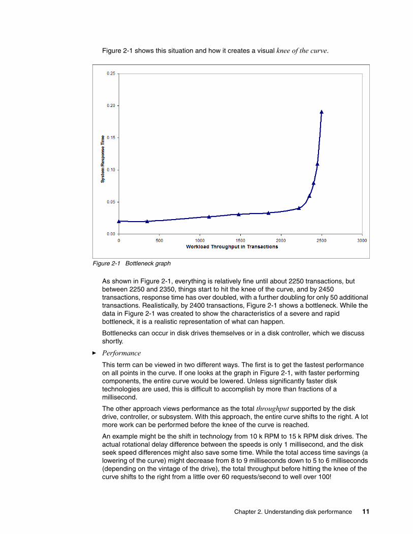
Figure 2-1 shows this situation and how it creates a visual knee of the curve.
Figure 2-1 Bottleneck graph
As shown in Figure 2-1, everything is relatively fine until about 2250 transactions, but between 2250 and 2350, things start to hit the knee of the curve, and by 2450 transactions, response time has over doubled, with a further doubling for only 50 additional transactions. Realistically, by 2400 transactions, Figure 2-1 shows a bottleneck. While the data in Figure 2-1 was created to show the characteristics of a severe and rapid bottleneck, it is a realistic representation of what can happen.
Bottlenecks can occur in disk drives themselves or in a disk controller, which we discuss shortly.
� PerformanceThis term can be viewed in two different ways. The first is to get the fastest performance on all points in the curve. If one looks at the graph in Figure 2-1, with faster performing components, the entire curve would be lowered. Unless significantly faster disk technologies are used, this is difficult to accomplish by more than fractions of a millisecond.
The other approach views performance as the total throughput supported by the disk drive, controller, or subsystem. With this approach, the entire curve shifts to the right. A lot more work can be performed before the knee of the curve is reached.
An example might be the shift in technology from 10 k RPM to 15 k RPM disk drives. The actual rotational delay difference between the speeds is only 1 millisecond, and the disk seek speed differences might also save some time. While the total access time savings (a lowering of the curve) might decrease from 8 to 9 milliseconds down to 5 to 6 milliseconds (depending on the vintage of the drive), the total throughput before hitting the knee of the curve shifts to the right from a little over 60 requests/second to well over 100!
Chapter 2. Understanding disk performance 11
� Mirroring (RAID-1), RAID-5, and RAID-6These terms are storage protection approaches that protect the disk subsystem to different extents and cause differing levels of disk activity. They, therefore, impact the number and size of disk drives that are needed for a given level of system capacity and performance. We discuss these approaches in detail in:
– Appendix C, “Understanding RAID-5, RAID-6, and associated performance considerations” on page 73
– Appendix D, “Mirroring” on page 85.
Writes in RAID-5 and RAID-6 environments have hidden disk activity, which can, in turn, result in disk bottlenecks sooner than would be the case in a mirrored environment.
2.2 Disk drive considerations
While it might seem obvious, a physical disk drive can only perform a given number of physical accesses each second before performance is affected. Less obvious is the fact that performance is relatively constant until one gets to the knee of the curve for the drive, after which it rapidly degrades.
This degradation occurs because the actual response time of a disk access (disk arm movement, rotational delay, and data transfer time) are all relatively constant. However, as the number of disk requests increases, a new request might not be able to be acted upon immediately. This delay occurs when it needs to wait until the previous request has completed. This queuing time starts to cause delays. In addition, as the number of disk requests increase, the number of access requests that must be queued also increases, resulting in delays and creating the knee of the curve.
We use the term relatively constant here. The actual time for each specific access will vary depending on factors such as:
� The amount of disk arm movement (the further the arm must move, the longer that portion of the access takes).
� The exact location of the data on the disk track when the arm is first positioned, which determines the rotational delay (on average, this will be one half of a disk rotation, with a 15 k rpm disk a single rotation is 4 milliseconds, so the average rotational delay is 2 milliseconds).
� The amount of data transferred (larger transfers take slightly more time).
Therefore, with a 15 k rpm disk an individual access can take 6 plus or minus 1 ½ milliseconds. However, if the disk is busy, the next disk access needs to wait through some portion of the previous disk request before it can even start. If the previous access was only half complete, the overall time could be more than 9 or 10 milliseconds before the just requested access is completed (3 milliseconds of queuing time, plus 6 milliseconds for the actual access). Therefore, it is important to configure the system to avoid the bottlenecks that occur with excessive queuing.
12 A Look at System i Integrated DASD Configuration and Performance under i5/OS
An analogy might help illustrate why performance remains relatively constant until a certain point, and then rapidly starts to fall off:
Picture a dart board with 1000 square inches of space (1000 milliseconds in a second). Darts (disk accesses) are thrown at this board so that they land totally randomly across the entire board. Unlike a real dart board, they will not cluster toward the center. Each dart is 6 square inches (6 milliseconds).
The first dart is thrown, and it is guaranteed to hit an empty space on the board. The next dart is thrown, and the odds are that 994/1000 of the time it will hit an empty space (a disk access with no queuing). Likewise, the odds of hitting the board without ever touching another dart are very high for a large number of additional darts. However, as the board gets fuller and fuller, the odds of not perfectly hitting an empty space and partially hitting another dart increases at an ever-increasing rate.
When another dart is partially hit, the amount of overlap of the hit represents the number of milliseconds of delay that occurs before the dart (disk access) can be processed. If the other dart is just nicked, the delay is short. If it is a direct impact, in disk terms, the delay could be 6 milliseconds. Until there are a relatively large number of darts on the board (disk accesses occurring in the same second) there are few hits (delays), but when too many darts are thrown (disk accesses requested), there are greater and greater odds of hitting other darts (more and more disk queuing).
There are three potential solutions for this problem:
– Throw less darts, that is request fewer disk accesses using smarter programming or more main memory in the System i.
– Spread the dart throwing among more boards, that is add disk drives.
– Use smaller darts, that is use faster disk drives.
At the disk level, a 10 k rpm disk drive will take about 8 to 9 milliseconds per physical access and can usually perform a little more than 60 disk accesses/second (as reported by the system in a RAID-5 environment) before the disks start to bottleneck.
With 15 k rpm disks, the physical disk access time is closer to 6 milliseconds, and well over 100 disk accesses can be performed each second without bottlenecking the disks.
There is one final consideration at the disk drive level. The actual capacity of the disk drive has very little to do with the performance of an individual disk access. While a 70 GB disk drive might have a few more disk platters or a few more disk read/write heads, it still has only one disk actuator. The speed difference for a single disk access might be one or two tenths of a millisecond different between the different capacity disk drives. Over time, newer technologies allow the same capacity disk drives to perform more rapidly than older drives (for example, a 15 k rpm disk drive sold today is usually faster than a 15 k rpm disk drive sold three years ago). This speed difference can be greater than the speed difference between different capacity drives.
However, customers installing 70 GB disk drives sometimes install only half the number of drives that they would have installed had they been using 35 GB disks. This means that each disk drive will need to do twice as many disk requests each second. This is not a problem if the resulting number of accesses each second is still below the knee of the curve. However, if it results in too many disk requests occurring on too few disk drives, performance can suffer! The same is true when 140 GB drives are used instead of 70 GB drives.
Note: This is at the per disk level and assumes there are no bottlenecks in the controller (which we will discuss shortly).
Chapter 2. Understanding disk performance 13
So far, we have discussed the disk drives themselves. A component of equal or greater importance to overall performance is the disk controller.
2.3 Disk controller considerations
Just as a disk can only perform a given number of requests each second (before a bottleneck develops), the same is true of the disk controller. Different controllers have the capacity to perform different numbers of disk requests each second. Smaller or slower controllers might only have a few disks attached and can only support a few hundred accesses each second. Larger or faster controllers can support up to 36 disks (not recommended for all workloads) and well over 1000 requests each second.
As a general rule of thumb, the high speed disk controllers available prior to the February 2007 announcement (#2757/2780 and #5580/5581) were usually capable of about 900 to 1200 disk requests/second/controller (assuming RAID-5, with 6 k to 12 k of data transferred per request and a 50/50 read to write ratio. With other access characteristics the numbers need adjusting. (See Appendix G, “A real-world approach to sizing disks for adequate performance” on page 101 for more information). The recommendation was to size to 900 requests/second to allow peaks of 1200 (which was just starting into the knee of the curve for the controller). If one were to size for 1200 requests/second, at peak times the number is exceeded and performance can be impacted.
While 10 k rpm disks can be used with these controllers, a bottleneck will usually occur with the disks themselves, long before the controller is stressed. Therefore, 15 k rpm disks are recommended. With 15 disks attached (most frequent situation in a #5094/5294 tower), the recommendation was about 900/15 = 60 disk operations/second (ops), and with 12 disks attached (the capacity of a #5095 tower), the recommendation was 900/12 = 75 ops. Therefore, the disk controller usually becomes a bottleneck before the disk drives (which are capable of over 100 ops).
With the controllers announced in February 2007, the amount of workload that can be processed before a controller bottleneck occurs increases greatly. We discuss the particulars later in the paper, but for now, suffice it to say that when running the newest disk controller with RAID-5 (#5782/5783) supporting disks in #0595/5094/5095/5294 towers, the disks become the bottleneck (at somewhere more than 100 requests/second, using the parameters described earlier), before the controllers bottleneck.
The new disk controller used with the EXP24 enclosure (an enclosure that can house 24 disk drives) can support the attachment of 36 disk drives (1½ EXP24s), but the attachment of 24 disks is usually optimal. Because of the increased processing capacity of the new controller, when running 24 disk drives, it should be able to support a sizing approach of about 65 ops to allow peaks of 80 ops.
Note: The 520/550/570/595 models are the last to support 8 GB and 17 GB 10 k rpm disks.
Note: These values might be conservative. Several of our test scenarios have shown capabilities in excess of these values, but until we have more real world data, we have chosen to go with the more conservative numbers. More details are provide in the performance capabilities reference manual (SC41-0607) and later in this paper.
14 A Look at System i Integrated DASD Configuration and Performance under i5/OS
2.4 Other considerations affecting disk sizing, performance, and availability
This section lists and discusses briefly several other items that affect disk sizing, performance, and availability. For most of the topics, we include only a short discussion here. We provide additional detail in Appendix C, “Understanding RAID-5, RAID-6, and associated performance considerations” on page 73 and Appendix D, “Mirroring” on page 85.
2.4.1 Overall disk sizing considerations
Earlier in this chapter, we discussed how the quantity of disk drives or too few disk controllers or less powerful disk controllers can cause a bottleneck to occur. We discussed things in terms of disk operations per second under specific conditions. We used this metric because it is easy to understand and acts as a good rule of thumb. It also allows relatively easy comparisons in various situations.
You can also see whether a specific controller with lower performance might be causing a bottleneck, even though other controllers might be performing well. We have seen situations on System i Model 520s where the disk controller in the processor enclosure was so overloaded that new disk requests to faster controllers could not occur. On smaller i520s, there might not be a lot of tasks running. Normally, when one task is waiting on disk, the system switches to another task. If there are not enough tasks running, a severe bottleneck can cause the entire system to wait.
Bottlenecks can also occur when new disks are added. This is especially important if the new disks have larger capacity than other disks on the system, in which case the system allocates more new data on these disks than existing disks. This can cause the system to, for a period of time, issue perhaps two to four times as many disk accesses as other smaller (½ or ¼ capacity) disks on the system. You can address this default possibility by using the Service Tools interfaces to not respread data after the disks are added, - in which case, these disks
Note: To achieve these performance levels, most System i disk controllers use write cache (not just write buffer) capabilities. Under certain circumstances (such as ignoring a warning about a backup write cache battery needing replacement), write cache might not be available, and performance will be affected. We discuss the importance of write cache in Appendix B, “Understanding disk write cache” on page 69.
Important: In reality, the levels of wait time and, therefore, the response time of the disk, for levels up to about 40% disk utilization, are usually good to excellent, and there is usually little disk queuing. If disk response times are increasing while there is minimal additional disk queuing, there can be locks or seizes, or controller overload conditions occurring. This information can then be used to determine if more disks or faster controllers might be needed or if fewer disks of larger capacity might be viable.
It is important to use performance measurements for a busy time of disk activity, not an average. iSeries Navigator can be used to determine the time periods with the greatest disk activity.
Running i5/OS Collection Services, generating the corresponding QAPMxxxx performance database files, and then reviewing Performance Tools for iSeries, 5722-PT1, reports can also be a way to determine the time periods with the greatest disk activity.
Chapter 2. Understanding disk performance 15
will be empty. Thus, when the system needs to extend a database, they will be the first disks used. And, of course, the newest data is typically the most heavily utilized.
Usually, system administrators only look at disk sizing considerations under one (or more) of three circumstances. Each has specific considerations. In each of these discussions, we discuss all the disks in a given Auxiliary Storage Pool (ASP) or LPAR. Using disks of differing capacity in different ASPs or LPARs does not have the same issues associated as mixing different capacity drives in the same ASP or LPAR.
1. More disk capacity is needed.
Using the same capacity disks is always the safe thing to do, but it might not be the most cost-effective. This is especially the case if older or slower disks or controllers are used and if there is an opportunity to re-evaluate the disk subsystem from perspectives such as maintenance cost and physical space considerations as well as performance. If you can see that the current disk drives are running at low levels of utilization (operations per second, not capacity), it might be possible to add larger capacity disks.
You need to be careful, however, when replacing existing disks. Picture the following situation:
A customer has several disk controllers on their system. All of them are supporting as many 35 GB disks as the disk controllers and enclosures will allow and are performing about 60 disk operations per second per disk. Performance is good. They need more capacity but do not want to purchase an additional enclosure or disk controller. They want to replace one of the existing RAID arrays consisting of seven 35 GB drives with seven 70 GB drives. Will this cause a problem?
Yes, it probably will. If we only look at the one controller with 15 disks, each of them has the same capacity and therefore will usually run about the same number of disk requests. When nearly half of those disks are replaced with double capacity drives, the workload will shift. Now nearly 2/3 of accesses need to occur on 7 of the disks—each drive is expected to perform over 110 disk operations/second during normal operations and far more at peak times. Therefore, the disks could bottleneck.
Additionally, there are multiple controllers on the system. Based on the information presented, we can assume each is currently doing about 900 accesses each second. Now, by putting nearly 50% more disk capacity on one of the controllers, there will be a shift of activity off of one of the controllers and onto the one with the greater capacity. The additional workload could result in a bottleneck at the controller level.
You can find additional examples of situations using mixed capacity disk drives in Appendix E, “Additional examples of situations using mixed capacity disk drives” on page 95.
Some general rules on sizing systems with different capacity disks:
– In general, if a disk subsystem is performing well, disks of double the capacity can be added, and performance will not decrease. This assumes that the data on the disks will be respread after the new drives are added. And that significant additional workload is not being added to the system.
– Do not mix disks in the same ASP with a difference of 4 times the capacity, unless proper analysis has been performed first.
– When considering replacing disks with fewer double capacity drives (of the same speed and using disk controllers with similar performance), analysis needs to be performed to ensure that sufficient disk arms will be available.
– Replacing smaller capacity disks with new drives with larger capacity might not cause a problem if the new disks will be 15 k rpm and the disk controller is replaced at the
16 A Look at System i Integrated DASD Configuration and Performance under i5/OS
same time. This is due to the fact that when 15 k rpm disks are used, the disk controller, not the disk drives, usually causes the first bottleneck.
2. System performance is suffering due to the disk subsystem being overloaded.This situation usually occurs at one of two times. Either when a new disk configuration (or additional drives) is implemented and proper sizing or analysis was not performed or over time as additional workload is added to the existing disk subsystem. In either of these situations, analysis needs to be performed to determine if additional disk controller or disk drives need to be added, or if the solution might be as simple as replacing some older/slower disk controllers (especially pre-#2757 vintage) with newer, faster controller technology.
There can also be a situations where a processor upgrade causes a disk bottleneck (but since from an overall perspective, things got faster, the bottleneck might not be recognized). In this case, for functions such as batch jobs, the processor now spends less time between each disk access and is therefore able to request more accesses each second. A bottleneck could move from the processor to the disk subsystem, which cannot keep up with the new volume, but because the overall runtime decreases, the problem might not even be noticed.
Another situation might occur when a new release of the operating system is installed or system parameters are altered (especially if a function like expert cache is turned off). New releases of i5/OS usually provide documentation indicating potential differences in operations. New functions that use the disk more heavily might be implemented. It is especially important to read the memo to users if the system is close to being in a bottleneck situation.
It is not our intent to provide details about potential solutions to disk performance problems, but the first thing that needs to happen is to run performance reports for a busy time period. System Navigator can be used first to determine the time period or periods that need to be examined.
It is more important to be able to analyze a few busy time periods than an average where everything appears to be running within normal parameters. Consider the following situation:
Most of the time, a #2757 or #2780 disk controller might be handling 500 to 600 disk requests per second, but for a 1 hour time period each day, it is asked to handle 1400 requests. On average, everything is comfortably below 800 to 900 disk accesses, but during the peak time, a bottleneck occurs.
If the bottleneck is severe enough, it can be difficult to analyze things fully. This is because the performance reports will not be as useful as one would hope. The performance reports are only able to report on what is actually happening. There might be pent up demand that cannot be processed.
For example, a system could be having performance problems when trying to perform 1300 disk requests on a single disk controller (that starts to bottleneck at 1200 requests) with 15 disk drives attached. Once the bottleneck is removed, one might find that the system is now doing 1800 or more disk requests/second (due to pent-up demand that couldn’t be processed).
Fortunately, the solution to this scenario is probably to add more disks and an additional disk controller. This new environment then has sufficient capacity to handle the 1800 operations. However, another solution might have been to replace the #2757, #2780, #5581, or #5580 disk controller with a newer faster #5582 or #5583. While the new controller could indeed handle the additional workload, and the disks themselves would have been able to function at full speed at 1300 I/Os per second (1300/15 = 86 ops per drive), if the real demand was 1800 I/Os per second, the disks could start to bottleneck,
Chapter 2. Understanding disk performance 17
especially during peak situations (when the requests exceed the 120 ops/second that occur at 1800 ops at the controller level).
While the analysis can take a little time, the needed solutions are usually fairly straightforward.
3. The system is being upgraded or replaced with a newer/larger system.
“To Keep or Not to Keep”—that is the often the question asked about the disk subsystems. Several parameters need to be considered. Speed and capacity of the existing disk drives and controllers, replacement costs, space requirements, and ongoing Maintenance costs are some of them. These concerns are compounded by the fact that additional capacity or performance might be needed.
Fortunately, the following general rules and approaches can help:
– Eliminate all 10 k RPM disks, all drives smaller than 35 GB, and all controllers older than #2757s. There is a significant performance difference between 10 k and 15 k RPM disks. This is not so much in terms of milliseconds (usually only about 1 to 3 milliseconds difference as reported by the system), but due to the fact that a 10 k RPM disk drive will start to bottleneck at a little over 60 disk operations/second (ops), while the 15 k disk can exceed 100 ops.
Disks smaller than 35 GB are usually still using older or slower controllers and the speed difference between a #2757 or newer compared to all older disk controllers allows it to perform about 3 times as many operations per second without bottlenecking. The use of fewer, larger disks also results in less space and lower maintenance costs.
You should also replace all #5074, #5079, and older towers. They do not support 15k RPM disks. They also do not support the new disk controllers announced in 2007. They will not be supported on future system models beyond the 520, 550, 570, and 595.
– Determine how many disk operations are currently being performed at peak times by reviewing performance reports. Examine the reports to make sure there are no current bottlenecks that would allow more activity if the bottleneck was not occurring.
Adjust the level of workload to account for the characteristics of the new system:
• The processor is faster. There is the potential for it to generate additional workload (especially during batch runs when there is no user intervention to slow down the process). Therefore, more disk requests could occur.
• New systems are usually configured with more memory. This can reduce the amount of paging and other disk activity, especially if the current system was undersized on memory.
– After determining the requirements for the new system, determine which disks and controllers to keep. Then determine how many new disks and controllers are needed. Make sure to recognize that within each ASP, double capacity disks will be performing twice as many disk requests each second as their smaller counterparts.
Analyze both the needed capacity and the level of activity that will be occurring on each disk to determine a configuration that meets the needs, but does not cause bottlenecks. We provide additional guidance later in this paper.
– New rack-mounted disk enclosures and controllers (discussed in Chapter 3, “Large read and write cache disk controllers and enclosures” on page 23) provide significant space savings and potentially require fewer disk controllers than older technologies. While it might not be cost-effective to replace a #2757/2780/5580/5581 with a newer controller in a #5094/5294 tower, the space savings of moving to rack-mounted enclosures might make such a change viable.
18 A Look at System i Integrated DASD Configuration and Performance under i5/OS
– If converting to mirroring, the same number of double capacity disks can be usually be used without impacting performance (see the next section and Appendix D, “Mirroring” on page 85).
2.4.2 Mirroring compared to RAID-5 or RAID-6
In the past, RAID-5 has been the most popular disk protection approach. Today’s technology, application environment, and pricing make mirroring at a minimum of the controller (not just disk level) the suggested approach for several reasons, including:
� Components other than disks can experience failures. While RAID-5 allows continued processing during a disk outage, a disk controller outage will cause the system (or at least the LPAR or Independent Auxiliary Storage Pool) to stop. If the controllers are mirrored and a controller failure occurs, the system will continue to run and process during the outage.
Mirroring also provides a higher level of disk-level protection than RAID-5, but in very rare instances, RAID-6 can provide a very slight disk protection advantage over mirrored disks but not over mirrored disk controllers. You need to recognize that RAID-6 only protects at the disk level and does not protect against controller outages. The possibility of a controller outage is far greater than the very rare situations where RAID-6 might provide a disk protection advantage over mirroring. Also, RAID-6 has performance considerations that need to be evaluated. Mirroring provides a performance advantage over RAID-5 and a very significant performance advantage over RAID-6.
� While disks and controllers are very reliable components, the increasing capacities demanded by today’s environments could require a greater number of components and, therefore, a greater possibility of a single device failing.
� The cost of downtime has increased and the ability to recover data has become more difficult. When RAID-5 became popular, most processing was done by customer employees. If a failure occurred the operations often could continue and after the failure was corrected. Employees could catch up and re-key any data that had not been on the backup tapes.
In today’s Internet-driven world, customers themselves are often entering the data. They do so in real time. If the system is down, they might go to a competitor. Or even worse, they might have entered data and received an order acknowledgment prior to the system going down. After the system is restored to operation, how will the data be reconstructed? How might this inability to fulfill an order that the customer thinks that they have placed, but that the system has no knowledge of the order placement after the failure, affect customer relationships and future orders?
These are all reasons to implement a full resiliency solution (using a second system). There are also other things that can be done (such as journaling with periodic saves) to minimize the impact of a system restore (which can happen in a RAID-5 or RAID-6 environment if a controller without auxiliary write cache fails). While mirroring cannot prevent all outages, it allows systems to continue to function during situations that would have caused an outage in a RAID-5 or RAID-6 environment. The net is, the additional cost of mirroring can often be viewed as a cheap insurance policy.
� Technology advantages allow today’s disk controllers and disk drives to perform far more disk requests each second than was the case when RAID-5 became popular. Because of the increases in disk capacities and controller performance, today’s recommendation is to use double capacity disks in a mirrored environment. The exact same number of double capacity disks (or sometimes fewer) are used for mirroring as for RAID-5. If the system required 20 disk arms to meet the performance objectives, it would not matter if these were 20 of the 35 GB disk arms in a RAID-5 environment, of 20 of the 70 GB disks in a
Chapter 2. Understanding disk performance 19
mirrored environment. In both cases, there would be 20 disk arms to meet the performance objective, and the mirrored disks would actually provide greater capacity.
For a far more comprehensive discussion, see Appendix D, “Mirroring” on page 85, and “Using double capacity disks in a mirrored environment” on page 91.
2.4.3 The importance of auxiliary write cache
This discussion is blunt and to the point. It is important that it is understood. The topic is briefly discussed here. Additional detail is available in Appendix C, “Understanding RAID-5, RAID-6, and associated performance considerations” on page 73.
If a customer is remaining RAID-5, RAID-6, mirroring at the disk (not controller) level, or has not protected their disks, and the disk controller fails, the system (or LPAR or Independent ASP) is going to stop. How long it is out of service will depend on various factors.
Ideally, after the service representative arrives and installs the replacement disk controller, the system will come back up and function. However, there is a potential problem. Depending on how the disk controller failed, there might still be data in write cache in the controller that has not yet been written to disk. Depending on the specific situation, the cache might or might not be recoverable from the failing controller card. If it is not recoverable and if this data is important (which is almost always the case), a system reload (or at minimum an LPAR or IASP reload) can be required.
Fortunately, a feature called Auxiliary Write Cache provides a solution. A copy of the cache from the controller card is stored on a different card. When data is written to the disk controller, it is updated in both the controller itself and on the Auxiliary Write Cache feature. This is done without impacting performance of the controller or the system. If the disk controller were to fail and needs replacement, and if there was data on the disk controller write cache which was not recoverable, the auxiliary write cache is used to restore the cache on the new controller. The data is then written out to disk, and operations can resume.
In a RAID-5 or RAID-6 environment, the difference in downtime can be hours instead of a day or more. This is why IBM configurators automatically specify using an auxiliary write cache feature for #2780 or newer high performance disk controllers in a RAID-5 environment (new placements of #2757 features are no longer available, or it would apply there also). It is strongly encouraged that any #2757/#2780 features being used with RAID-5 are updated (for a charge) with this additional capability, or that the controller is replaced with a newer one with auxiliary write cache. Note: The high performance controllers announced in February 2007 will not even allow RAID-5 or RAID-6 to be used without an auxiliary write cache feature, and if such use is attempted, will disable the write cache (thereby affecting performance, but better protecting the data).
Installation of the auxiliary write cache features on existing controllers requires planning, because additional PCI slots are needed and additional IOPs might be needed. In some cases RAID-5 or RAID-6 arrays might need to be reduced in size. This is because a
Note: If the system sizing was more contingent on capacity than on the number of disks needed for performance, fewer double capacity disks might be viable in a mirrored environment than in a RAID-5 or RAID-6 configuration.
Note: If the system is mirrored at the controller or higher levels and a disk controller fails, the system keeps on running, and data on the drives that are still operational continue to be updated.
20 A Look at System i Integrated DASD Configuration and Performance under i5/OS
#2757/2780/571E controller without the write cache feature can support 20 disks, but with the write cache, only 15 drives are supported.
In a controller-level or better mirrored environment, the auxiliary write cache is not needed. This is because the data in it becomes out of date while the “other side of the mirror” allows the system to continue to run. Instead of using an auxiliary write cache for the recovery, the data on the drives on the “other side of the mirror” is used to reconstruct the data on the drives attached to the replaced controller. See Appendix D, “Mirroring” on page 85 for additional information.
As mentioned earlier, Appendix C, “Understanding RAID-5, RAID-6, and associated performance considerations” on page 73 contains additional information about RAID-5 or RAID-6 and Auxiliary Write Cache.
2.4.4 Other disk subsystem functions affecting performance
The disk subsystem supported by i5/OS is quite sophisticated compared to that found on other platforms. Some of the additional functionality is discussed in Appendix A, “System i integrated disk capabilities that require a SAN on other systems” on page 65, and Appendix B, “Understanding disk write cache” on page 69.
Note: There is a new auxiliary write cache feature that can be used with both the #2757/#2780 and with the new disk controllers announced in February 2007. We discuss the feature in Chapter 3, “Large read and write cache disk controllers and enclosures” on page 23. We mention it here because new purchases of auxiliary cache features for the #2757/2780 should use the new feature (for example, use a #5590/5591 feature instead of a #5580/5581 feature) if running V5R3 of i5/OS or later. The price is the same. This allows the feature to be used on the current controllers today, then moved/reused if the controller is replaced in the future.
Chapter 2. Understanding disk performance 21

22 A Look at System i Integrated DASD Configuration and Performance under i5/OS
Chapter 3. Large read and write cache disk controllers and enclosures
In February 2007, IBM made several disk subsystem announcements for the System i. Two new disk controllers (using several different feature numbers) were announced, as well as new rack-mounted and standalone disk enclosures.
The new disk controllers can significantly boost I/O performance with faster electronics and twice the write cache of the existing #2780/#5580 controllers. While the new controllers have the potential to provide far more performance, do not expect to see disk access speeds increase (unless an existing controller is currently causing a bottleneck). Instead, the new controllers provide similar access speeds at greater levels of disk activity. To put this in terms discussed earlier in the paper, the knee of the curve (at which point performance starts to suffer) moves significantly to the right. Therefore, the new disk controllers allow 15 k rpm disk drives to perform more operations each second without affecting performance.
The new disk I/O drawer or tower is called the TotalStorage® EXP24. It allows up to 24 disks to be installed in a rack mounted drawer or stand-alone tower. Unlike previous disk enclosures for the System i, the enclosure houses only disk drives, not the disk controller. The disk controller is placed in a pair of PCI-X slots in a PCI-X enclosure, and SCSI cables from the controller attach directly to features in the EXP24.
This chapter describes the various features one at a time, starting with the new controllers that are similar in usage to the previously available #2780/5580 disk controllers. It then covers the new disk enclosures and the new controller features used with the new enclosures. We also discuss how the currently available #5776 (Smart IOA (without an IOP (also commonly referred to as IOPless) and its corresponding #5737 (using an IOP) disk controller can be used with the new disk enclosures.
3
© Copyright IBM Corp. 2008. All rights reserved. 23
3.1 New disk controllers used with existing (#5094/5294) disk towers
New PCI-X disk controllers, #5738 and #5777, provide additional performance capabilities with faster electronics and twice the write cache as their predecessor, the #2780. Mirroring is supported through operating system support and RAID-5 and RAID-6 capabilities are supported through the disk controller. An auxiliary write cache IOA is required for RAID-5 and RAID-6 environments (the RAID-5 or RAID-6 function cannot be enabled or used if the auxiliary write cache feature is not present). Auxiliary write cache is very strongly recommended for disk-only mirroring environments but not for mirroring at the controller (IOA) level or higher. For RAID-5 or RAID-6 environments, features #5582 and #5583 include a combination of a disk controller and the auxiliary write cache.
Technical advantages of the #5738 and #5777 PCI-X disk controllers include a 1.5 GB write cache and 1.6 GB read cache—twice the amount of write cache and 60% more read cache than provided by the predecessor #2780 disk controller. The controllers use a PowerPC® processor and double data rate (DDR-2) memory technology. These capabilities usually allow higher utilization levels of the attached disks without impacting performance.
This controller has four different feature numbers that all use the same CCIN part number (the number shown on rack configurations and used if the server personnel need to replace a part). Which feature is used depends on:
� Whether the controller will be used as a smart IOA (IOPless) or in an IOP-based mode
� Whether the controller is used in a RAID-5 or RAID-6 mode or in an unprotected or mirrored mode
The features are different to ensure that needed IOPs and auxiliary write cache capabilities are included by the configuration tools. If in the future an IOP is no longer needed for the new disk controllers, the same physical card can be used in an IOPless mode (assuming it is a POWER5 or later system running V5R4 or a later release of i5/OS).
� The #5777 is a smart IOA (IOP-less) for POWER5, or later, systems cannot be used with 8xx models (which do not support IOPless capabilities). Using the smart IOA capability requires i5/OS running V5R4 or higher. It saves the cost of an IOP, and provides additional configuration flexibility, especially in an LPAR environment. It can be used in the i5 system unit or in a #0595, #5094, #5294, or #5095 tower.
� The #5738 is an IOP-based controller for 800, 810, 825, 870, 890, and later models. i5/OS running at V5R3 or later is required. It can be placed in an 825 system unit or a #0595, #5094, #5095, #5294, #8294, or #9194 I/O tower (which are the I/O enclosures associated with 870/890 systems). Unlike the #2780 and #5580, it cannot be located in a model 800 or 810 system unit.
3.1.1 Auxiliary write cache features for new #5738/5777 IOAs and older#2757/2780 IOAs
New auxiliary write cache IOAs (with 1.5 GB write cache to match the new disk controller's write cache) are available to help protect against long outages in the event a disk controller fails when running RAID-5, RAID-6, or device-level mirroring.
To use the functions of RAID-5 or RAID-6, the PCI-X 1.5 GB Disk Controller requires a 1.5 GB Auxiliary Write Cache IOA to be attached. A RAID-5/RAID-6 array cannot be created or started. without the Auxiliary write cache. If the auxiliary cache is removed or fails after the RAID-5/RAID-6 array is created, the PCI-X 1.5 GB Disk Controller will not use its write cache
24 A Look at System i Integrated DASD Configuration and Performance under i5/OS
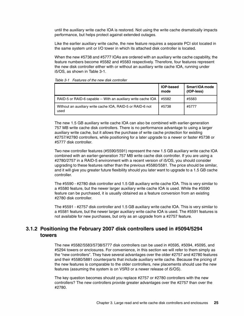
until the auxiliary write cache IOA is restored. Not using the write cache dramatically impacts performance, but helps protect against extended outages.
Like the earlier auxiliary write cache, the new feature requires a separate PCI slot located in the same system unit or I/O tower in which its attached disk controller is located.
When the new #5738 and #5777 IOAs are ordered with an auxiliary write cache capability, the feature numbers become #5582 and #5583 respectively. Therefore, four features represent the new disk controller either with or without an auxiliary write cache IOA, running under i5/OS, as shown in Table 3-1.
Table 3-1 Features of the new disk controller
The new 1.5 GB auxiliary write cache IOA can also be combined with earlier-generation 757 MB write cache disk controllers. There is no performance advantage to using a larger auxiliary write cache, but it allows the purchase of write cache protection for existing #2757/#2780 controllers, while positioning for a later upgrade to a newer or faster #5738 or #5777 disk controller.
Two new controller features (#5590/5591) represent the new 1.5 GB auxiliary write cache IOA combined with an earlier-generation 757 MB write cache disk controller. If you are using a #2780/2757 in a RAID-5 environment with a recent version of i5/OS, you should consider upgrading to these features rather than the previous #5580/5581. The price should be similar, and it will give you greater future flexibility should you later want to upgrade to a 1.5 GB cache controller.
The #5590 - #2780 disk controller and 1.5 GB auxiliary write cache IOA. This is very similar to a #5580 feature, but the newer larger auxiliary write cache IOA is used. While the #5590 feature can be purchased, it is usually obtained as a feature conversion from an existing #2780 disk controller.
The #5591 - #2757 disk controller and 1.5 GB auxiliary write cache IOA. This is very similar to a #5581 feature, but the newer larger auxiliary write cache IOA is used. The #5591 features is not available for new purchases, but only as an upgrade from a #2757 feature.
3.1.2 Positioning the February 2007 disk controllers used in #5094/5294 towers
The new #5582/5583/5738/5777 disk controllers can be used in #0595, #5094, #5095, and #5294 towers or enclosures. For convenience, in this section we will refer to them simply as the “new controllers”. They have several advantages over the older #2757 and #2780 features and their #5580/5881 counterparts that include auxiliary write cache. Because the pricing of the new features is comparable to the older controllers, new placements should use the new features (assuming the system is on V5R3 or a newer release of i5/OS).
The key question becomes should you replace #2757 or #2780 controllers with the new controllers? The new controllers provide greater advantages over the #2757 than over the #2780.
IOP-based mode
Smart IOA mode (IOP-less)
RAID-5 or RAID-6 capable -- With an auxiliary write cache IOA #5582 #5583
Without an auxiliary write cache IOA, RAID-5 or RAID-6 not used
#5738 #5777
Chapter 3. Large read and write cache disk controllers and enclosures 25
Features include:
� Like the #2780, but unlike the #2757, the new controllers provide a readily accessible battery that can continue to power the write cache in the event of a power outage or other failures. On the #2757, the system must be powered down before the battery can be replaced. With the #2780 and the new controllers, cache battery replacement is performed under concurrent maintenance
� The new controllers have 60% more read cache capacity than the #2780. The #2757 doesn’t have read cache. In most i5/OS application environments, this difference is not expected to provide significant performance benefits.
� The write cache of the new controllers is about double the size of the write cache on the #2757/2780. Unless the current system is experiencing write cache overruns, the additional capacity is not usually a benefit. One of the reasons for the increased capacities of both the read and write caches is that it is anticipated that larger capacity disks will often be used with the new controllers.
� Unlike the #2757/2780, the new controllers enforce the requirement for Auxiliary Write Cache in a RAID-5 or RAID-6 environment. RAID-5 or RAID-6 cannot be started/used if the auxiliary write cache feature is not available. This was put in place to try to ensure shorter outages in the event of a disk controller card outage.
� The auxiliary write cache feature used with the new controllers can also be purchased/used with existing #2757/2780 controllers (use features #5891/5890), and then reused with the new controllers once the #2757/2780 is replaced. The additional capacity of this write cache feature is not used by the #2757/2780 but will be available if it is later transferred to one of the new controllers.
� The new controllers can sustain higher operations per second rates than the previous generation. This might allow larger capacity disks to be used.
� There are limitations in the number of these controllers that can be placed in #0595, #5094, #5095, or #5294 towers and enclosures. We discuss the details later in this paper.
� When used on systems using POWER5 or newer processors and with V5R4 or later editions of i5/OS, the new controllers can run without an IOP. This can reduce the number of PCI slots needed and reduce costs. It also makes LPAR planning easier.
� The new controllers support RAID-6, but the overhead associated with RAID-6 needs to be considered. Most customers needing more availability than RAID-5 can provide should be considering mirroring (at a minimum of the controller level) rather than RAID-6.
When all of these features are evaluated, most customers will probably not replace existing #2757/2780 features with these new controllers, unless they are experiencing bottlenecks in their current environment. They might, however, evaluate replacing the older controllers with controllers used with the EXP24 Disk Enclosure, which we discuss in the next section.
3.2 TotalStorage EXP24 disk enclosure features and capabilities
The new #5786 or #5787 TotalStorage EXP24 disk drawer or tower offers an economical attachment of up to 24 disk drives in a small space. This enclosure does not have any PCI slots. Its disk drives are driven by one or more disk controllers located in a System i system unit or I/O tower or drawer. It is attached through an external SCSI connection (using SCSI cables of various lengths). With appropriate disk IOAs, the EXP24 can be used with System i 800, 810, 825, 870, 890, and Power5 and later models. i5/OS V5R3, or later, is required.
A key advantage of the EXP24 #5786 compared to other disk capable I/O towers and drawers is the efficiency of its footprint space and the flexibility of its placement. Up to 24 disk drives are contained in just 4U of 19-inch rack space. Compared to the #5294 1.8m I/O tower with
26 A Look at System i Integrated DASD Configuration and Performance under i5/OS
up to 90 disk drives, a 36U rack with eight EXP24 #5786 can hold up to 192 disk drives. This is more than twice the number of disk drives for the same footprint. A 42U rack supports up to 240 disk drives (33.8 TB of storage when using 141.12 GB disks. Actual usable storage will usually be less, because the above capacities reflect the storage available when not using mirroring or RAID-5/RAID-6 protection).
Like previous internal or integrated System i disk storage, the EXP24 disk tower or drawer and its disk drives are optional feature numbers. The disk drives that are placed in the EXP24 disk enclosure are identical to the drives provided for 520, 550, 570, and 595 models. However, different disk feature numbers are used to designate their placement in a #5786 or #5787 EXP24 disk drawer or tower to help the IBM configuration tools. These features include the i5/OS supported 15k rpm drives #1266, #1267, and #1268, and the AIX 5L/Linux supported 10k and 15k rpm drives #1293 to #1299. Existing i5/OS 10k rpm disk drives are not supported in these enclosures.
Because the disk drives are identical, there will be no performance difference in the disks themselves. However, because the higher speed or capacity controllers are usually used, the number of disk operations per second each drive can accomplish can often be increased without hitting the knee of the curve. This assumes that you do not place so many disks on the new controller that it overwhelms its increased speed.
In the past, with 15 k rpm disks, the disk controller was usually the constraining factor, with the newer faster controllers, depending on how many disks are attached, the disks themselves can become the constraining factor.
The #5786 is a disk drawer that requires only 4U (4 EIA units) of rack space. The #5787 is a tower or deskside configuration. Conversions from rack-to-tower or tower-to-rack are not provided. Each #5786 and #5787 has redundant power supplies and dual power cords for higher availability.
Each EXP24 disk unit is organized into four 6-packs of disk slots. A disk controller can drive either one or two 6-packs on each SCSI connection. Depending on the disk controller being used, it can provide up to 3 SCSI connections. To enable the 6-packs, two different features are specified for the EXP24:
� If there will only be 6 disks (one 6-pack) attached to a single SCSI bus from the controller, a #5741, EXP24 6 Disk Slot Enabler is used.
� If there will be 12 disks (two 6-packs) attached to a single SCSI bus from the controller, a #5742, EXP24 6/12 Disk Slot Enabler feature is used with the first 6-pack. It is attached to the disk controller using a SCSI cable. There is a second port on the 6/12 enabler to allow attachment to a second disk slot enabler through a second SCSI cable. A #5741, EXP24 6 Disk Slot Enabler is then attached to the first 6/12 disk slot enabler through a SCSI cable to enable the second 6-pack.
Therefore, the choice between 6 or 12 disk slots per SCSI connection is determined by which features are used. One Disk Slot Enabler feature must be used for each 6-pack into which a disk drive is placed.
The most common EXP24 configuration usually includes two #5742 EXP24 6/12 disk slot enablers and two #5741 6 disk slot enabler features. To use these features, four SCSI cables must be specified. Two are usually 0.55 meters in length. Each of these goes from one 6/12
Note: In the past, the high speed controllers could only attach 15 or 20 disks, but with the new EXP24 controller, the new high speed controller can physically attach up to 36 disks (1 ½ EXP24 enclosures. However, for a “best practices performance directive,” we usually recommend a maximum of 24 disks.
Chapter 3. Large read and write cache disk controllers and enclosures 27
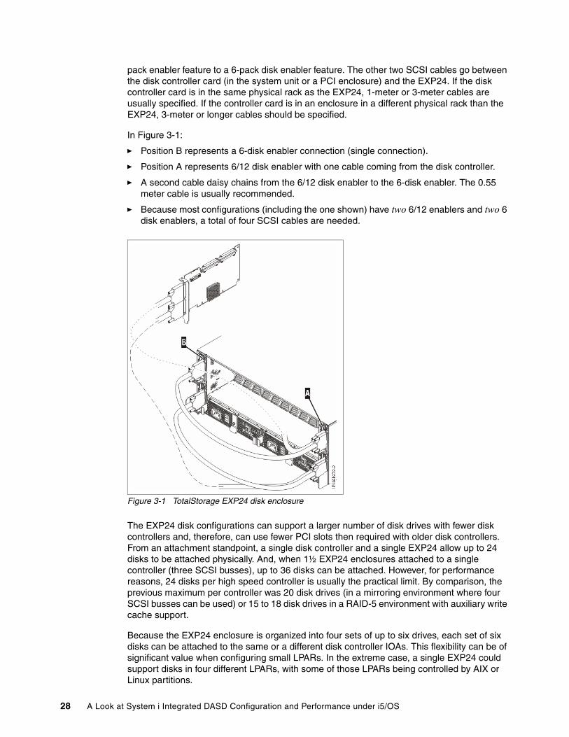
pack enabler feature to a 6-pack disk enabler feature. The other two SCSI cables go between the disk controller card (in the system unit or a PCI enclosure) and the EXP24. If the disk controller card is in the same physical rack as the EXP24, 1-meter or 3-meter cables are usually specified. If the controller card is in an enclosure in a different physical rack than the EXP24, 3-meter or longer cables should be specified.
In Figure 3-1:
� Position B represents a 6-disk enabler connection (single connection).
� Position A represents 6/12 disk enabler with one cable coming from the disk controller.
� A second cable daisy chains from the 6/12 disk enabler to the 6-disk enabler. The 0.55 meter cable is usually recommended.
� Because most configurations (including the one shown) have two 6/12 enablers and two 6 disk enablers, a total of four SCSI cables are needed.
Figure 3-1 TotalStorage EXP24 disk enclosure
The EXP24 disk configurations can support a larger number of disk drives with fewer disk controllers and, therefore, can use fewer PCI slots then required with older disk controllers. From an attachment standpoint, a single disk controller and a single EXP24 allow up to 24 disks to be attached physically. And, when 1½ EXP24 enclosures attached to a single controller (three SCSI busses), up to 36 disks can be attached. However, for performance reasons, 24 disks per high speed controller is usually the practical limit. By comparison, the previous maximum per controller was 20 disk drives (in a mirroring environment where four SCSI busses can be used) or 15 to 18 disk drives in a RAID-5 environment with auxiliary write cache support.
Because the EXP24 enclosure is organized into four sets of up to six drives, each set of six disks can be attached to the same or a different disk controller IOAs. This flexibility can be of significant value when configuring small LPARs. In the extreme case, a single EXP24 could support disks in four different LPARs, with some of those LPARs being controlled by AIX or Linux partitions.
28 A Look at System i Integrated DASD Configuration and Performance under i5/OS
3.3 Disk controllers that support the EXP24 disk drawer and tower
Two types of disk controllers announced in January 2006 now support the attachment of the #5686 and #5687 EXP24 drawer and tower:
� The entry #0647, #5736, and #5775 disk controllers with zero write cache
� The RAID-5/RAID-6 capable #0648, #5737, and #5776 disk controllers with 90 MB write cache
Originally, these disk controllers were most frequently used to support disks in the system unit or in a #5095/0595 12-disk enclosure.
The #0647, #5736, and #5775 can attach physically a maximum of one SCSI connection and a maximum of six disk drives (one 6-pack). Because these controllers do not have write cache capabilities, using them could affect performance.
The #0648, #5737, and #5776 attach physically a maximum of two SCSI connections and a maximum of 24 disk drives (two 12-packs). However, because this is not a high-speed controller, attaching this number of drives might affect performance.
Realistically, a maximum of 12 disk drives might be viable in a mirrored environment if performance planning is done first. About 10 drives usually is the more practical limit. In a RAID-5 environment, up to seven or eight disks can be viable, and in a RAID-6 environment, about six disks is usually the practical limit. The actual limit is determined by the amount of activity that is expected out of each disk drive. These guidelines are based on using the controllers in a mixed environment with disks attached to the existing #2780/5580 controllers running at recommended usage levels. For RAID-5, this level is usually about 60 disk operations/second/disk (to allow peaks of 80 ops) when using a 1:1 read-to-write ratio, and disk accesses averaging 8 to 12 k in size.
In addition to these announced controllers, a new disk controller with large read and write caches was also announced in February 2007. It uses a PowerPC processor, DDR-2 memory, PCI-X technology, and use large caches. This enables the best possible performance and a large number of disk drives to be supported on these disk controllers. The EXP24 1.5 GB Disk Controller is a double-wide PCI-X DDR technology card that provides 1.5 GB write cache and 1.6 GB read cache. It has 1.5 GB of auxiliary write cache built into its double-wide packaging and does not need a separate auxiliary write cache IOA and cable. This controller can provide mirroring, RAID-5, and RAID-6 capabilities. It is similar to the #5582 and #5583 disk controllers with auxiliary write cache features (that are used with #5094 and #5294 towers).
The EXP24 1.5 GB disk controller has three SCSI connections and can support a maximum of 36 disk drives (three 12-packs). It can be located in a 5xx or 825 model system unit or in a
Note: The reason this controller is a double-wide PCI-X feature is due to the number of components that need to be included on the cards (external SCSI adapters and an externally accessible battery-back-up for the write cache). To take full advantage of the two slots, this controller always includes the auxiliary write cache capability. (If we had not built the feature this way, the addition of auxiliary write cache would have required a third PCI slot.) While auxiliary write cache is not normally thought of as providing a benefit in a controller (or higher) level mirroring environment, it does provide an advantage in the very unlikely occurrence where a disk fails on one side of a mirror, and then the controller on the other side of the mirror fails prior to the replacement of the failing disk drive.
Chapter 3. Large read and write cache disk controllers and enclosures 29
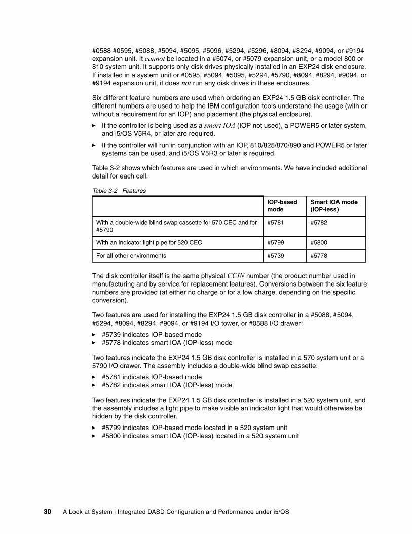
#0588 #0595, #5088, #5094, #5095, #5096, #5294, #5296, #8094, #8294, #9094, or #9194 expansion unit. It cannot be located in a #5074, or #5079 expansion unit, or a model 800 or 810 system unit. It supports only disk drives physically installed in an EXP24 disk enclosure. If installed in a system unit or #0595, #5094, #5095, #5294, #5790, #8094, #8294, #9094, or #9194 expansion unit, it does not run any disk drives in these enclosures.
Six different feature numbers are used when ordering an EXP24 1.5 GB disk controller. The different numbers are used to help the IBM configuration tools understand the usage (with or without a requirement for an IOP) and placement (the physical enclosure).
� If the controller is being used as a smart IOA (IOP not used), a POWER5 or later system, and i5/OS V5R4, or later are required.
� If the controller will run in conjunction with an IOP, 810/825/870/890 and POWER5 or later systems can be used, and i5/OS V5R3 or later is required.
Table 3-2 shows which features are used in which environments. We have included additional detail for each cell.
Table 3-2 Features
The disk controller itself is the same physical CCIN number (the product number used in manufacturing and by service for replacement features). Conversions between the six feature numbers are provided (at either no charge or for a low charge, depending on the specific conversion).
Two features are used for installing the EXP24 1.5 GB disk controller in a #5088, #5094, #5294, #8094, #8294, #9094, or #9194 I/O tower, or #0588 I/O drawer:
� #5739 indicates IOP-based mode� #5778 indicates smart IOA (IOP-less) mode
Two features indicate the EXP24 1.5 GB disk controller is installed in a 570 system unit or a 5790 I/O drawer. The assembly includes a double-wide blind swap cassette:
� #5781 indicates IOP-based mode� #5782 indicates smart IOA (IOP-less) mode
Two features indicate the EXP24 1.5 GB disk controller is installed in a 520 system unit, and the assembly includes a light pipe to make visible an indicator light that would otherwise be hidden by the disk controller.
� #5799 indicates IOP-based mode located in a 520 system unit � #5800 indicates smart IOA (IOP-less) located in a 520 system unit
IOP-based mode
Smart IOA mode (IOP-less)
With a double-wide blind swap cassette for 570 CEC and for #5790
#5781 #5782
With an indicator light pipe for 520 CEC #5799 #5800
For all other environments #5739 #5778
30 A Look at System i Integrated DASD Configuration and Performance under i5/OS
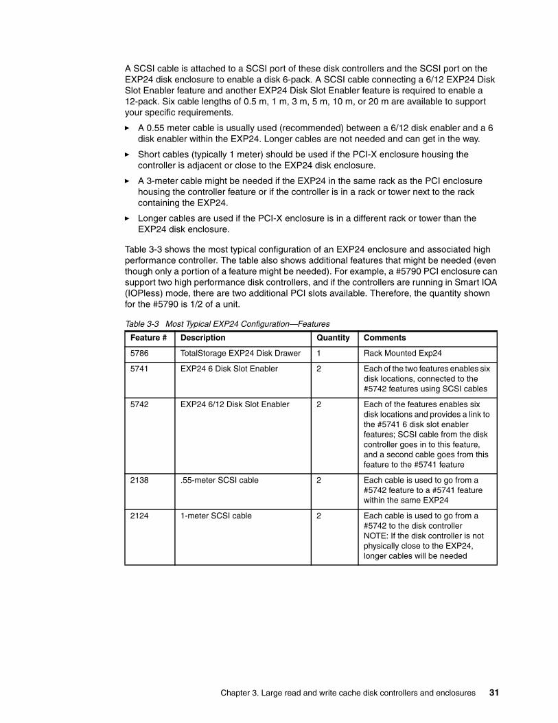
A SCSI cable is attached to a SCSI port of these disk controllers and the SCSI port on the EXP24 disk enclosure to enable a disk 6-pack. A SCSI cable connecting a 6/12 EXP24 Disk Slot Enabler feature and another EXP24 Disk Slot Enabler feature is required to enable a 12-pack. Six cable lengths of 0.5 m, 1 m, 3 m, 5 m, 10 m, or 20 m are available to support your specific requirements.
� A 0.55 meter cable is usually used (recommended) between a 6/12 disk enabler and a 6 disk enabler within the EXP24. Longer cables are not needed and can get in the way.
� Short cables (typically 1 meter) should be used if the PCI-X enclosure housing the controller is adjacent or close to the EXP24 disk enclosure.
� A 3-meter cable might be needed if the EXP24 in the same rack as the PCI enclosure housing the controller feature or if the controller is in a rack or tower next to the rack containing the EXP24.
� Longer cables are used if the PCI-X enclosure is in a different rack or tower than the EXP24 disk enclosure.
Table 3-3 shows the most typical configuration of an EXP24 enclosure and associated high performance controller. The table also shows additional features that might be needed (even though only a portion of a feature might be needed). For example, a #5790 PCI enclosure can support two high performance disk controllers, and if the controllers are running in Smart IOA (IOPless) mode, there are two additional PCI slots available. Therefore, the quantity shown for the #5790 is 1/2 of a unit.
Table 3-3 Most Typical EXP24 Configuration—Features
Feature # Description Quantity Comments
5786 TotalStorage EXP24 Disk Drawer 1 Rack Mounted Exp24
5741 EXP24 6 Disk Slot Enabler 2 Each of the two features enables six disk locations, connected to the #5742 features using SCSI cables
5742 EXP24 6/12 Disk Slot Enabler 2 Each of the features enables six disk locations and provides a link to the #5741 6 disk slot enabler features; SCSI cable from the disk controller goes in to this feature, and a second cable goes from this feature to the #5741 feature
2138 .55-meter SCSI cable 2 Each cable is used to go from a #5742 feature to a #5741 feature within the same EXP24
2124 1-meter SCSI cable 2 Each cable is used to go from a #5742 to the disk controller NOTE: If the disk controller is not physically close to the EXP24, longer cables will be needed
Chapter 3. Large read and write cache disk controllers and enclosures 31

3.4 Positioning the new disk controllers and EXP24 disk enclosures
Because there are so many different feature numbers used for the new controllers that support disks in the EXP24 enclosure, we refer to them as new controllers for the EXP24 enclosure in this section.
We anticipate that the EXP24 enclosure and the controllers used with it will rapidly become the approach of choice for new purchases of integrated disks when more than 12 disks are needed (the #5095/0595 enclosures are still viable for supporting 12 disks).
The #5737 and #5776 90 MB cache controllers announced in January 2006 can also be used with the EXP24 enclosure. When originally announced, these controllers supported a maximum of 12 disk drives. With the announcement of the EXP24, they can now physically attach up to 24 disks. However, for performance reasons, most customers will not want to attach more than about six to 10 disks to these controllers (depending on whether they are running RAID-6, RAID-5, or mirroring) For more information, see 3.3, “Disk controllers that support the EXP24 disk drawer and tower” on page 29. Therefore, these disks are viable for use with relatively small LPARs but will probably not be used when there are large disk requirements.
The new disk controllers for the EXP24 enclosure can attach physically up to 36 disk drives (1½ EXP24s), but in most environments, for optimum performance, 24 disks will usually be attached. When that number of disks are attached, the number of disk requests/second/drive, in a mirrored or RAID-5 environment, will be approximately equal to what can be obtained on a #2757/2780/5580/5581 disk controller with 15 disks attached. Therefore, adding fully populated EXP24s with one new controller per EXP24 will produce disk activity levels compatible with existing disks attached to the #2757/2780 controllers.
Smart IOA Disk Controller 1 One of six different high performance disk controllers; the specific feature number is dependent upon whether an IOP is used or whether it is running in Smart IOA mode (requires minimum of POWER5 hardware and V5R4 of i5/OS). Lower performance/capacity disk controllers can also be used if controlling a minimal number or low usage disks
Typical features required to house the disk controller cards
5790 PCI Card enclosure 0.5 Allocated portion for a single controller
7311 5790 Mounting Hardware 0.25 Allocated portion for a single controller
0551 Approximately 1/6 allocation of Rack
0.17 Portion of rack needed to house allocated 5790 plus EXP24
7188 Approximately 1/6 allocation PDU 0.17 Portion of Rack Power Distribution Unit
Feature # Description Quantity Comments
32 A Look at System i Integrated DASD Configuration and Performance under i5/OS
In addition to supporting more disk drives, the new controllers used with the EXP24 have several advantages over the #2757 and #2780 features and their #5580/5881 counterparts that include auxiliary write cache. The new controllers always include the auxiliary write cache capability. The card itself is, therefore, two PCI slots wide, which can impact placement decisions. We discuss placement information in 4.3, “Card placement rules” on page 39. Additional information is available at:
http://www.redbooks.ibm.com/redpieces/pdfs/redp4011.pdf
Other characteristics of the new controllers used with the EXP24 include:
� Like the #2780 and other controllers announced in February 2007, these new controllers provide a readily accessible battery that can continue to power the write cache in the event of a power outage or other failures. On the #2757, the system needed to be powered down before the battery could be replaced (actually, only the card needed to be powered down, but this usually resulted in the associated LPAR being unusable (unless independent ASPs were in use). With the #2780 and the new controllers, battery replacement is performed under concurrent maintenance
� The new controllers have about double the read and write cache capacities of the #2780. This helps provide support for the greater number of disk drives that can be attached to the controller. The size of the auxiliary write cache capability (a standard feature) is also doubled.
� The new controllers have more performance. About 35% more disk I/Os can occur without bottlenecking the controller. This allows more disks to be attached while maintaining the same I/O levels. If the same number of disks are attached as on older controllers, it may allow larger capacity disks to be used.
� There is a limit of two of these features in a #5790 PCI Expansion Drawer, and only one in a #5088 enclosure. Adding these controllers to #0595/#5094/#5096/#5095/#5294/#5296 enclosures, that also have controllers supporting disks in those towers, is subject to specific rules and restrictions.
We discuss placement information in 4.3, “Card placement rules” on page 39. Additional information is available at:
http://www.redbooks.ibm.com/redpieces/pdfs/redp4011.pdf
� When used with V5R4 or later editions of i5/OS, on a system using a POWER5 or later processor, the new controllers can run without an IOP. This can reduce the number of PCI slots needed and reduce costs. It also makes LPAR planning easier.
� The new controllers support RAID-6, but the overhead associated with RAID-6 needs to be considered. Most customers needing more availability than RAID-5 can provide should be considering mirroring (at a minimum of the controller level) rather than RAID-6.
� A 1.8-meter rack full of EXP24 disk enclosures and sufficient #5790 PCI enclosures to house the controllers can contain 144 disks. A 2-meter rack can contain 192 disks. This is 60% or 113% more than the 90 disks that can be contained in a #5294 tower.
� Existing 15 k rpm disk drives currently housed in the system unit or disk towers can be moved to be housed in EXP24 enclosures, but the feature numbers will change. Planning is needed to ensure RAID-5/RAID-6 arrays and disk mirrors are maintained, or modified to allow more disk drives in one or more of the RAID-5/RAID-6 arrays.
� The EXP24 enclosure can support disks in up to four LPARs—all running off different disk controllers. When this is done, the 90 MB controllers might be worth considering.
Note: If RAID-6 is used, the number of disk requests will be approximately 30% less than in a RAID-5 environment.
Chapter 3. Large read and write cache disk controllers and enclosures 33
You can use these considerations to determine whether you want to replace existing equipment with the new features. To a great extent, the decision will be based on the age of the current disk controllers, the speed (10 k or 15 k rpm) and capacity of existing disk drives, the lower physical space requirements, and whether the current controllers are currently using auxiliary write cache for RAID-5 or RAID-6 environments.
When moving drives from a #5094/5294 tower to an EXP24 array, there is often the opportunity to change many of the RAID-5 or RAID-6 sets. In a #5094/5294 tower, most customers use 15 disks per controller and create 2 RAID-5 arrays—one with eight disks and one with seven.
Both of these arrays can be moved into the EXP24. An additional disk can then be added to the 7-drive array. When this is first done, because the parity for the 7-drive array was spread across four disks, the resulting 8-disk array will still have the parity on only four of the eight drives. If RAID-5 is stopped, then restarted for this array (can be time consuming and make sure you have a backup first, because during the process the disks will be unprotected) the parity can be spread across all eight drives in the array. This results in a more balanced utilization of the disks.
34 A Look at System i Integrated DASD Configuration and Performance under i5/OS
Chapter 4. Planning and installation considerations for large cache disk controllers
This chapter discusses minimum firmware, microcode, and software levels that are required to support the 1.5 GB write cache adapter and the EXP24 1.5 GB write cache adapter. It reviews the rules for placement of these adapters within a supported I/O enclosure. It also includes information that pertains to parity sets and the EXP24 disk enclosure implementation planning.
4
© Copyright IBM Corp. 2008. All rights reserved. 35
4.1 Minimum code levels
Before installing the new 1.5 GB PCI-X Disk Controller or EXP 24 1.5 GB Disk Controller, you must have the following appropriate levels:
� Server firmware� i5/OS Licensed Internal Code (LIC)� i5/OS� Hardware Management Console (HMC) firmware
For the most current information about prerequisite code, consult the IBM Prerequisite Web pages at:
http://www-912.ibm.com/e_dir/eServerPrereq.nsf
As of March 2007, the minimum code requirements are:
� Feature 5738, PCI-X 1.5 GB Disk Controller (IOP controlled)
– i5/OS and licensed internal code (LIC) levels:
• i5/OS V5R4: RS 540-10 OS1 and RS 540-D LIC2 with cumulative PTF package C62975403 (or later). Also required are the following PTFs: MF41048, MF40503, and MF40836.
• i5/OS V5R3: RS530-10 OS1 and RS535-D LIC2 cumulative PTF package C6255530 (or later) with the following PTFs: MF41047, MF40505, and MF40845
• i5/OS V5R3: RS 530-10 OS and RS 530-J LIC cumulative PTF package C6255530 (or later) with the following PTF: MF41046
– Server firmware: FW2.4.0 SF240_261
� Feature 5777, PCI-X 1.5 GB Disk Controller (smart-IOA)
– i5/OS and licensed internal code (LIC) levels:
• i5/OS V5R4: RS 540-10 OS and RS 540-D LIC cumulative PTF package C6297540 (or later) with the following PTFs: MF41048, MF40503, and MF40836
– Server firmware: FW2.4.0 SF240_261
� Feature 5739 PCI-X EXP24 1.5 GB Disk Controller (IOP controlled)
� Feature 5781 PCI-X EXP24 1.5 GB Disk Controller (570/#5790 blind swap cassette, IOP controlled)
1 RSxyz-aa OS is a specific level of the distribution media for i5/OS. For information about how to verify this level of i5/OS is installed on the system, see:http://www-912.ibm.com/s_dir/slkbase.nsf/1ac66549a21402188625680b0002037e/55efb8de456ce35c86256da4004fa40a?OpenDocument&Highlight=0,respin
2 RS xyz-b LIC is a specific level of the distribution media for i5/OS Licensed Internal Code. Consult the URL in the previous footnote for additional information about verifying the level of LIC is installed on the system.
3 Equivalent i5/OS functionality can also be obtained by applying the Fix Level PTF cumulative package. However, you need to order the indicated refresh media for backup purposes.
36 A Look at System i Integrated DASD Configuration and Performance under i5/OS
� Feature 5799 PCI-X EXP24 1.5 GB Disk Controller (520, IOP controlled)
– i5/OS and licensed internal code (LIC) levels:
• i5/OS V5R4: RS 540-10 OS and RS 540-D LIC cumulative PTF package C6297540 (or later) with the following PTFs: MF40475, MF40476, MF40477, MF40738, MF40830, MF40468, MF41048, MF40503, and MF40836
• i5/OS V5R3: RS530-10 OS & RS535-D LIC cumulative PTF package C6255530 (or later) with the following PTFs: MF40623, MF40624, MF40625, MF40835, MF40829, MF40466, MF41047, MF40505, and MF40845
• i5/OS V5R3: RS 530-10 OS & RS 530-J LIC cumulative PTF package C6255530 (or later) with the following PTFs: MF40626, MF40627, MF40828, MF40463, and MF41046
– Server firmware: FW2.4.0 SF240_261
– HMC firmware: V6 R1.1 + latest eFixes
For more information, see:
http://www14.software.ibm.com/webapp/set2/sas/f/hmc/power5/download/v61.Update.html
� Feature 5778 PCI-X EXP24 1.5 GB Disk Controller (IOP controlled)Feature 5782 PCI-X EXP24 1.5 GB Disk Controller (570/#5790 blind swap cassette, runs IOP controlled)Feature 5800 PCI-X EXP24 1.5 GB Disk Controller (520, IOP controlled)
– i5/OS and licensed internal code (LIC) levels
i5/OS V5R4: RS 540-10 OS & RS 540-D LIC cumulative PTF package C6297540 (or later) with the following PTFs: MF40475, MF40476, MF40477, MF40738, MF40830, MF40468, MF41048, MF40503, and MF40836
– Server firmware: FW2.4.0 SF240_261
– HMC firmware: V6 R1.1 + latest eFixes
For more information, see:
http://www14.software.ibm.com/webapp/set2/sas/f/hmc/power5/download/v61.Update.html
� Features 5786 and 5787 EXP24 TotalStorage Disk Enclosure
– i5/OS and licensed internal code (LIC) levels:
• i5/OS V5R4: RS 540-10 OS and RS 540-D LIC cumulative PTF package C6297540 (or later)
• i5/OS V5R3: RS530-10 OS and RS535-D LIC cumulative PTF package C6255530 or later
• i5/OS V5R3: RS 530-10 OS and RS 530-J LIC cumulative PTF package C6255530 or later
– Server firmware: FW2.2.5 SF225_095
Chapter 4. Planning and installation considerations for large cache disk controllers 37
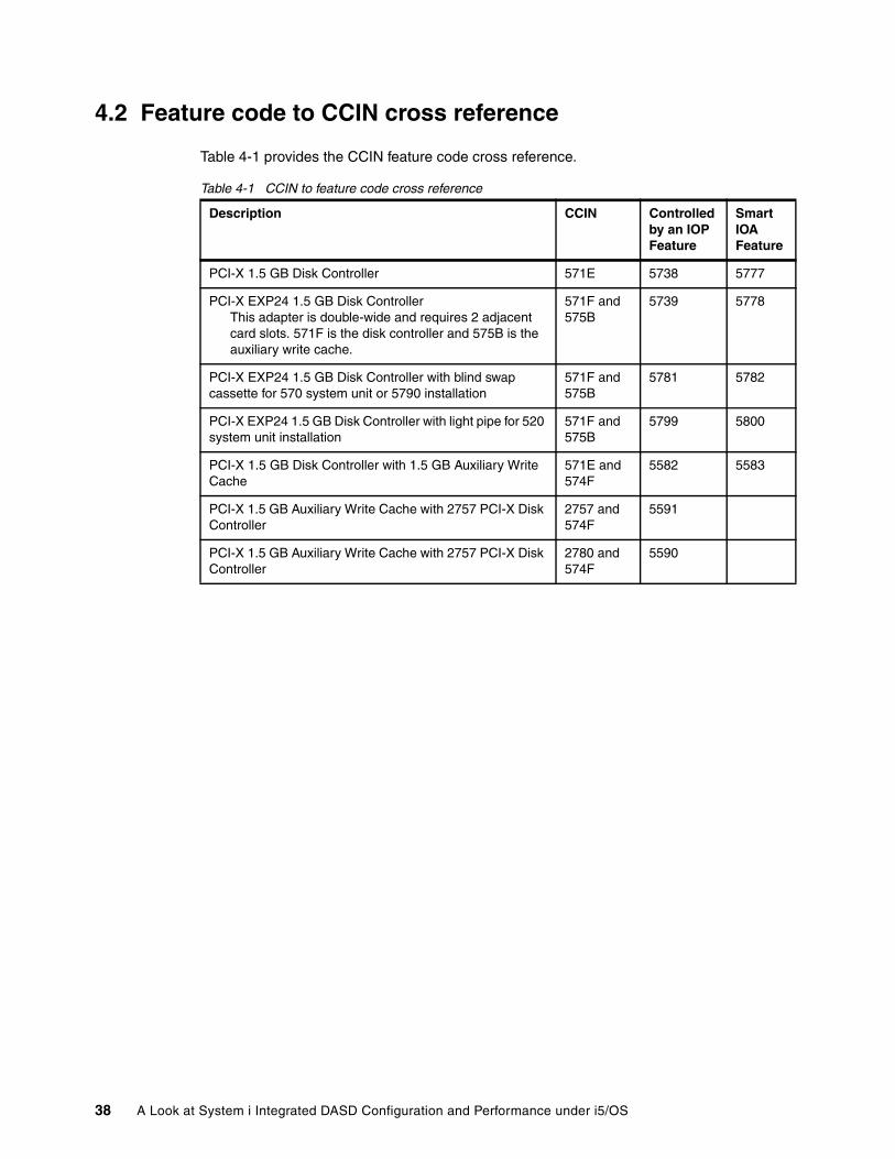
4.2 Feature code to CCIN cross reference
Table 4-1 provides the CCIN feature code cross reference.
Table 4-1 CCIN to feature code cross reference
Description CCIN Controlled by an IOP Feature
Smart IOA Feature
PCI-X 1.5 GB Disk Controller 571E 5738 5777
PCI-X EXP24 1.5 GB Disk ControllerThis adapter is double-wide and requires 2 adjacent card slots. 571F is the disk controller and 575B is the auxiliary write cache.
571F and 575B
5739 5778
PCI-X EXP24 1.5 GB Disk Controller with blind swap cassette for 570 system unit or 5790 installation
571F and 575B
5781 5782
PCI-X EXP24 1.5 GB Disk Controller with light pipe for 520 system unit installation
571F and 575B
5799 5800
PCI-X 1.5 GB Disk Controller with 1.5 GB Auxiliary Write Cache
571E and 574F
5582 5583
PCI-X 1.5 GB Auxiliary Write Cache with 2757 PCI-X Disk Controller
2757 and 574F
5591
PCI-X 1.5 GB Auxiliary Write Cache with 2757 PCI-X Disk Controller
2780 and 574F
5590
38 A Look at System i Integrated DASD Configuration and Performance under i5/OS
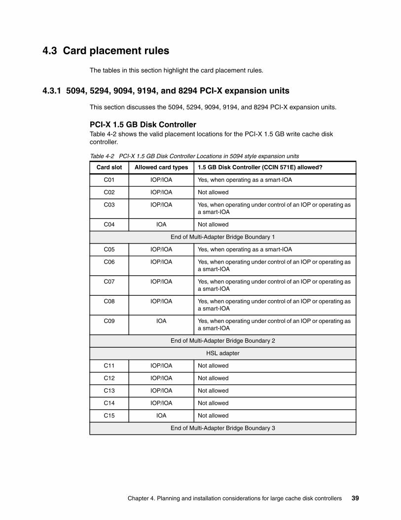
4.3 Card placement rules
The tables in this section highlight the card placement rules.
4.3.1 5094, 5294, 9094, 9194, and 8294 PCI-X expansion units
This section discusses the 5094, 5294, 9094, 9194, and 8294 PCI-X expansion units.
PCI-X 1.5 GB Disk ControllerTable 4-2 shows the valid placement locations for the PCI-X 1.5 GB write cache disk controller.
Table 4-2 PCI-X 1.5 GB Disk Controller Locations in 5094 style expansion units
Card slot Allowed card types 1.5 GB Disk Controller (CCIN 571E) allowed?
C01 IOP/IOA Yes, when operating as a smart-IOA
C02 IOP/IOA Not allowed
C03 IOP/IOA Yes, when operating under control of an IOP or operating as a smart-IOA
C04 IOA Not allowed
End of Multi-Adapter Bridge Boundary 1
C05 IOP/IOA Yes, when operating as a smart-IOA
C06 IOP/IOA Yes, when operating under control of an IOP or operating as a smart-IOA
C07 IOP/IOA Yes, when operating under control of an IOP or operating as a smart-IOA
C08 IOP/IOA Yes, when operating under control of an IOP or operating as a smart-IOA
C09 IOA Yes, when operating under control of an IOP or operating as a smart-IOA
End of Multi-Adapter Bridge Boundary 2
HSL adapter
C11 IOP/IOA Not allowed
C12 IOP/IOA Not allowed
C13 IOP/IOA Not allowed
C14 IOP/IOA Not allowed
C15 IOA Not allowed
End of Multi-Adapter Bridge Boundary 3
Chapter 4. Planning and installation considerations for large cache disk controllers 39
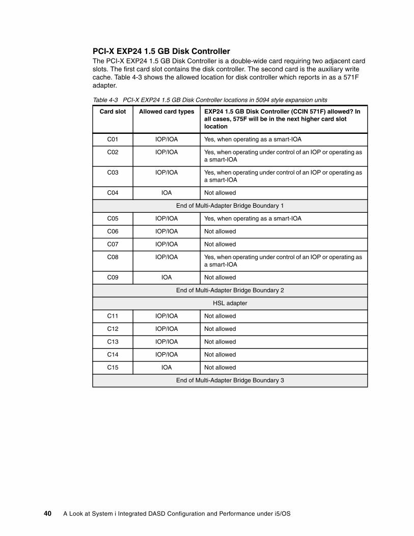
PCI-X EXP24 1.5 GB Disk ControllerThe PCI-X EXP24 1.5 GB Disk Controller is a double-wide card requiring two adjacent card slots. The first card slot contains the disk controller. The second card is the auxiliary write cache. Table 4-3 shows the allowed location for disk controller which reports in as a 571F adapter.
Table 4-3 PCI-X EXP24 1.5 GB Disk Controller locations in 5094 style expansion units
Card slot Allowed card types EXP24 1.5 GB Disk Controller (CCIN 571F) allowed? In all cases, 575F will be in the next higher card slot location
C01 IOP/IOA Yes, when operating as a smart-IOA
C02 IOP/IOA Yes, when operating under control of an IOP or operating as a smart-IOA
C03 IOP/IOA Yes, when operating under control of an IOP or operating as a smart-IOA
C04 IOA Not allowed
End of Multi-Adapter Bridge Boundary 1
C05 IOP/IOA Yes, when operating as a smart-IOA
C06 IOP/IOA Not allowed
C07 IOP/IOA Not allowed
C08 IOP/IOA Yes, when operating under control of an IOP or operating as a smart-IOA
C09 IOA Not allowed
End of Multi-Adapter Bridge Boundary 2
HSL adapter
C11 IOP/IOA Not allowed
C12 IOP/IOA Not allowed
C13 IOP/IOA Not allowed
C14 IOP/IOA Not allowed
C15 IOA Not allowed
End of Multi-Adapter Bridge Boundary 3
40 A Look at System i Integrated DASD Configuration and Performance under i5/OS
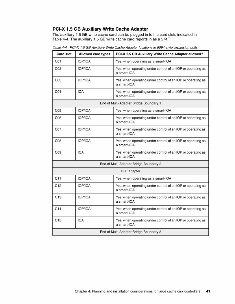
PCI-X 1.5 GB Auxiliary Write Cache AdapterThe auxiliary 1.5 GB write cache card can be plugged in to the card slots indicated in Table 4-4. The auxiliary 1.5 GB write cache card reports in as a 574F.
Table 4-4 PCI-X 1.5 GB Auxiliary Write Cache Adapter locations in 5094 style expansion units
Card slot Allowed card types PCI-X 1.5 GB Auxiliary Write Cache Adapter allowed?
C01 IOP/IOA Yes, when operating as a smart-IOA
C02 IOP/IOA Yes, when operating under control of an IOP or operating as a smart-IOA
C03 IOP/IOA Yes, when operating under control of an IOP or operating as a smart-IOA
C04 IOA Yes, when operating under control of an IOP or operating as a smart-IOA
End of Multi-Adapter Bridge Boundary 1
C05 IOP/IOA Yes, when operating as a smart-IOA
C06 IOP/IOA Yes, when operating under control of an IOP or operating as a smart-IOA
C07 IOP/IOA Yes, when operating under control of an IOP or operating as a smart-IOA
C08 IOP/IOA Yes, when operating under control of an IOP or operating as a smart-IOA
C09 IOA Yes, when operating under control of an IOP or operating as a smart-IOA
End of Multi-Adapter Bridge Boundary 2
HSL adapter
C11 IOP/IOA Yes, when operating as a smart-IOA
C12 IOP/IOA Yes, when operating under control of an IOP or operating as a smart-IOA
C13 IOP/IOA Yes, when operating under control of an IOP or operating as a smart-IOA
C14 IOP/IOA Yes, when operating under control of an IOP or operating as a smart-IOA
C15 IOA Yes, when operating under control of an IOP or operating as a smart-IOA
End of Multi-Adapter Bridge Boundary 3
Chapter 4. Planning and installation considerations for large cache disk controllers 41
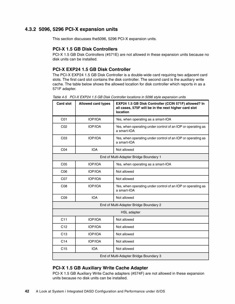
4.3.2 5096, 5296 PCI-X expansion units
This section discusses the5096, 5296 PCI-X expansion units.
PCI-X 1.5 GB Disk ControllersPCI-X 1.5 GB Disk Controllers (#571E) are not allowed in these expansion units because no disk units can be installed.
PCI-X EXP24 1.5 GB Disk ControllerThe PCI-X EXP24 1.5 GB Disk Controller is a double-wide card requiring two adjacent card slots. The first card slot contains the disk controller. The second card is the auxiliary write cache. The table below shows the allowed location for disk controller which reports in as a 571F adapter.
Table 4-5 PCI-X EXP24 1.5 GB Disk Controller locations in 5096 style expansion units
PCI-X 1.5 GB Auxiliary Write Cache AdapterPCI-X 1.5 GB Auxiliary Write Cache adapters (#574F) are not allowed in these expansion units because no disk units can be installed.
Card slot Allowed card types EXP24 1.5 GB Disk Controller (CCIN 571F) allowed? In all cases, 575F will be in the next higher card slot location
C01 IOP/IOA Yes, when operating as a smart-IOA
C02 IOP/IOA Yes, when operating under control of an IOP or operating as a smart-IOA
C03 IOP/IOA Yes, when operating under control of an IOP or operating as a smart-IOA
C04 IOA Not allowed
End of Multi-Adapter Bridge Boundary 1
C05 IOP/IOA Yes, when operating as a smart-IOA
C06 IOP/IOA Not allowed
C07 IOP/IOA Not allowed
C08 IOP/IOA Yes, when operating under control of an IOP or operating as a smart-IOA
C09 IOA Not allowed
End of Multi-Adapter Bridge Boundary 2
HSL adapter
C11 IOP/IOA Not allowed
C12 IOP/IOA Not allowed
C13 IOP/IOA Not allowed
C14 IOP/IOA Not allowed
C15 IOA Not allowed
End of Multi-Adapter Bridge Boundary 3
42 A Look at System i Integrated DASD Configuration and Performance under i5/OS
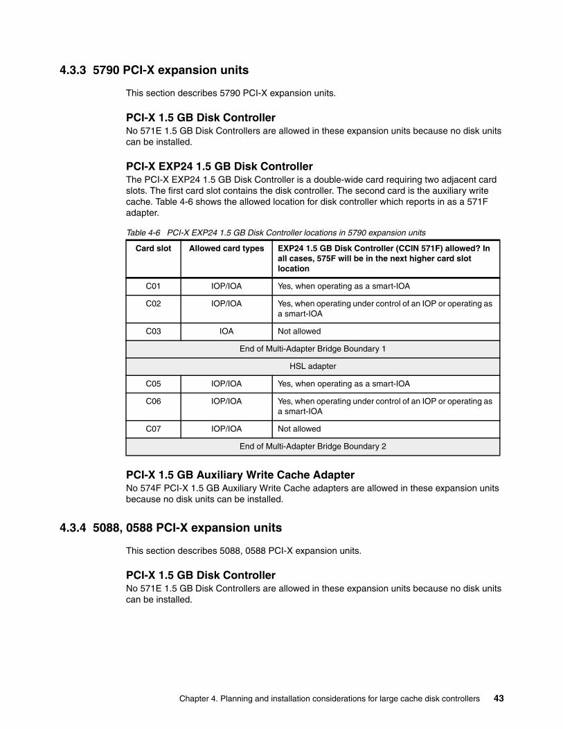
4.3.3 5790 PCI-X expansion units
This section describes 5790 PCI-X expansion units.
PCI-X 1.5 GB Disk ControllerNo 571E 1.5 GB Disk Controllers are allowed in these expansion units because no disk units can be installed.
PCI-X EXP24 1.5 GB Disk ControllerThe PCI-X EXP24 1.5 GB Disk Controller is a double-wide card requiring two adjacent card slots. The first card slot contains the disk controller. The second card is the auxiliary write cache. Table 4-6 shows the allowed location for disk controller which reports in as a 571F adapter.
Table 4-6 PCI-X EXP24 1.5 GB Disk Controller locations in 5790 expansion units
PCI-X 1.5 GB Auxiliary Write Cache AdapterNo 574F PCI-X 1.5 GB Auxiliary Write Cache adapters are allowed in these expansion units because no disk units can be installed.
4.3.4 5088, 0588 PCI-X expansion units
This section describes 5088, 0588 PCI-X expansion units.
PCI-X 1.5 GB Disk ControllerNo 571E 1.5 GB Disk Controllers are allowed in these expansion units because no disk units can be installed.
Card slot Allowed card types EXP24 1.5 GB Disk Controller (CCIN 571F) allowed? In all cases, 575F will be in the next higher card slot location
C01 IOP/IOA Yes, when operating as a smart-IOA
C02 IOP/IOA Yes, when operating under control of an IOP or operating as a smart-IOA
C03 IOA Not allowed
End of Multi-Adapter Bridge Boundary 1
HSL adapter
C05 IOP/IOA Yes, when operating as a smart-IOA
C06 IOP/IOA Yes, when operating under control of an IOP or operating as a smart-IOA
C07 IOP/IOA Not allowed
End of Multi-Adapter Bridge Boundary 2
Chapter 4. Planning and installation considerations for large cache disk controllers 43
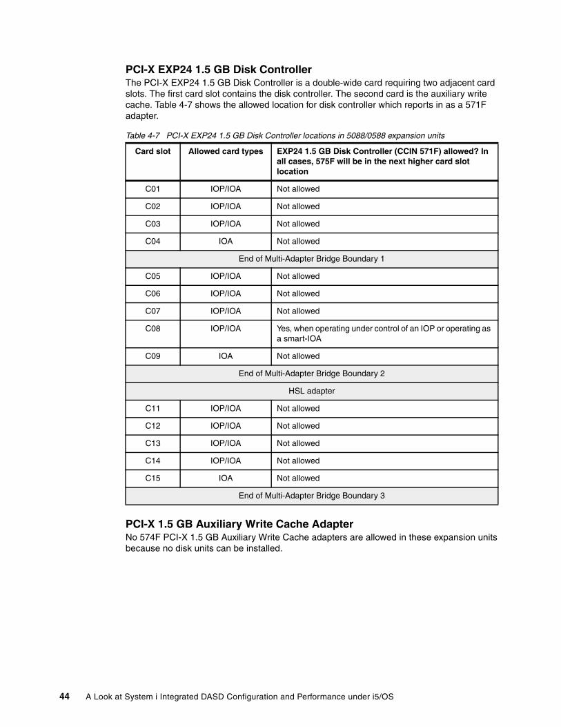
PCI-X EXP24 1.5 GB Disk ControllerThe PCI-X EXP24 1.5 GB Disk Controller is a double-wide card requiring two adjacent card slots. The first card slot contains the disk controller. The second card is the auxiliary write cache. Table 4-7 shows the allowed location for disk controller which reports in as a 571F adapter.
Table 4-7 PCI-X EXP24 1.5 GB Disk Controller locations in 5088/0588 expansion units
PCI-X 1.5 GB Auxiliary Write Cache AdapterNo 574F PCI-X 1.5 GB Auxiliary Write Cache adapters are allowed in these expansion units because no disk units can be installed.
Card slot Allowed card types EXP24 1.5 GB Disk Controller (CCIN 571F) allowed? In all cases, 575F will be in the next higher card slot location
C01 IOP/IOA Not allowed
C02 IOP/IOA Not allowed
C03 IOP/IOA Not allowed
C04 IOA Not allowed
End of Multi-Adapter Bridge Boundary 1
C05 IOP/IOA Not allowed
C06 IOP/IOA Not allowed
C07 IOP/IOA Not allowed
C08 IOP/IOA Yes, when operating under control of an IOP or operating as a smart-IOA
C09 IOA Not allowed
End of Multi-Adapter Bridge Boundary 2
HSL adapter
C11 IOP/IOA Not allowed
C12 IOP/IOA Not allowed
C13 IOP/IOA Not allowed
C14 IOP/IOA Not allowed
C15 IOA Not allowed
End of Multi-Adapter Bridge Boundary 3
44 A Look at System i Integrated DASD Configuration and Performance under i5/OS
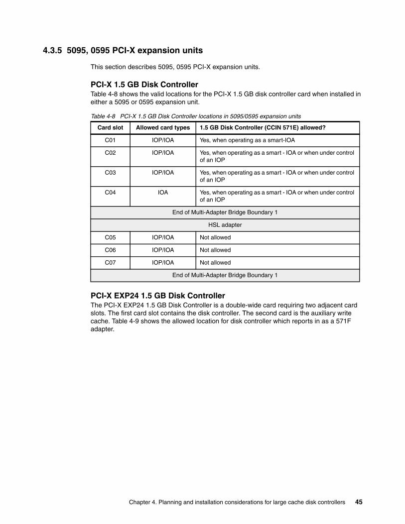
4.3.5 5095, 0595 PCI-X expansion units
This section describes 5095, 0595 PCI-X expansion units.
PCI-X 1.5 GB Disk ControllerTable 4-8 shows the valid locations for the PCI-X 1.5 GB disk controller card when installed in either a 5095 or 0595 expansion unit.
Table 4-8 PCI-X 1.5 GB Disk Controller locations in 5095/0595 expansion units
PCI-X EXP24 1.5 GB Disk ControllerThe PCI-X EXP24 1.5 GB Disk Controller is a double-wide card requiring two adjacent card slots. The first card slot contains the disk controller. The second card is the auxiliary write cache. Table 4-9 shows the allowed location for disk controller which reports in as a 571F adapter.
Card slot Allowed card types 1.5 GB Disk Controller (CCIN 571E) allowed?
C01 IOP/IOA Yes, when operating as a smart-IOA
C02 IOP/IOA Yes, when operating as a smart - IOA or when under control of an IOP
C03 IOP/IOA Yes, when operating as a smart - IOA or when under control of an IOP
C04 IOA Yes, when operating as a smart - IOA or when under control of an IOP
End of Multi-Adapter Bridge Boundary 1
HSL adapter
C05 IOP/IOA Not allowed
C06 IOP/IOA Not allowed
C07 IOP/IOA Not allowed
End of Multi-Adapter Bridge Boundary 1
Chapter 4. Planning and installation considerations for large cache disk controllers 45
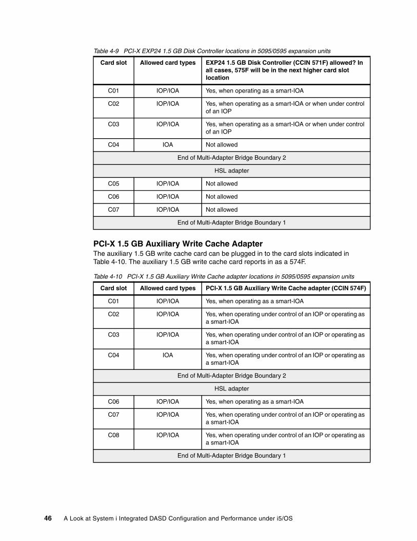
Table 4-9 PCI-X EXP24 1.5 GB Disk Controller locations in 5095/0595 expansion units
PCI-X 1.5 GB Auxiliary Write Cache AdapterThe auxiliary 1.5 GB write cache card can be plugged in to the card slots indicated in Table 4-10. The auxiliary 1.5 GB write cache card reports in as a 574F.
Table 4-10 PCI-X 1.5 GB Auxiliary Write Cache adapter locations in 5095/0595 expansion units
Card slot Allowed card types EXP24 1.5 GB Disk Controller (CCIN 571F) allowed? In all cases, 575F will be in the next higher card slot location
C01 IOP/IOA Yes, when operating as a smart-IOA
C02 IOP/IOA Yes, when operating as a smart-IOA or when under control of an IOP
C03 IOP/IOA Yes, when operating as a smart-IOA or when under control of an IOP
C04 IOA Not allowed
End of Multi-Adapter Bridge Boundary 2
HSL adapter
C05 IOP/IOA Not allowed
C06 IOP/IOA Not allowed
C07 IOP/IOA Not allowed
End of Multi-Adapter Bridge Boundary 1
Card slot Allowed card types PCI-X 1.5 GB Auxiliary Write Cache adapter (CCIN 574F)
C01 IOP/IOA Yes, when operating as a smart-IOA
C02 IOP/IOA Yes, when operating under control of an IOP or operating as a smart-IOA
C03 IOP/IOA Yes, when operating under control of an IOP or operating as a smart-IOA
C04 IOA Yes, when operating under control of an IOP or operating as a smart-IOA
End of Multi-Adapter Bridge Boundary 2
HSL adapter
C06 IOP/IOA Yes, when operating as a smart-IOA
C07 IOP/IOA Yes, when operating under control of an IOP or operating as a smart-IOA
C08 IOP/IOA Yes, when operating under control of an IOP or operating as a smart-IOA
End of Multi-Adapter Bridge Boundary 1
46 A Look at System i Integrated DASD Configuration and Performance under i5/OS
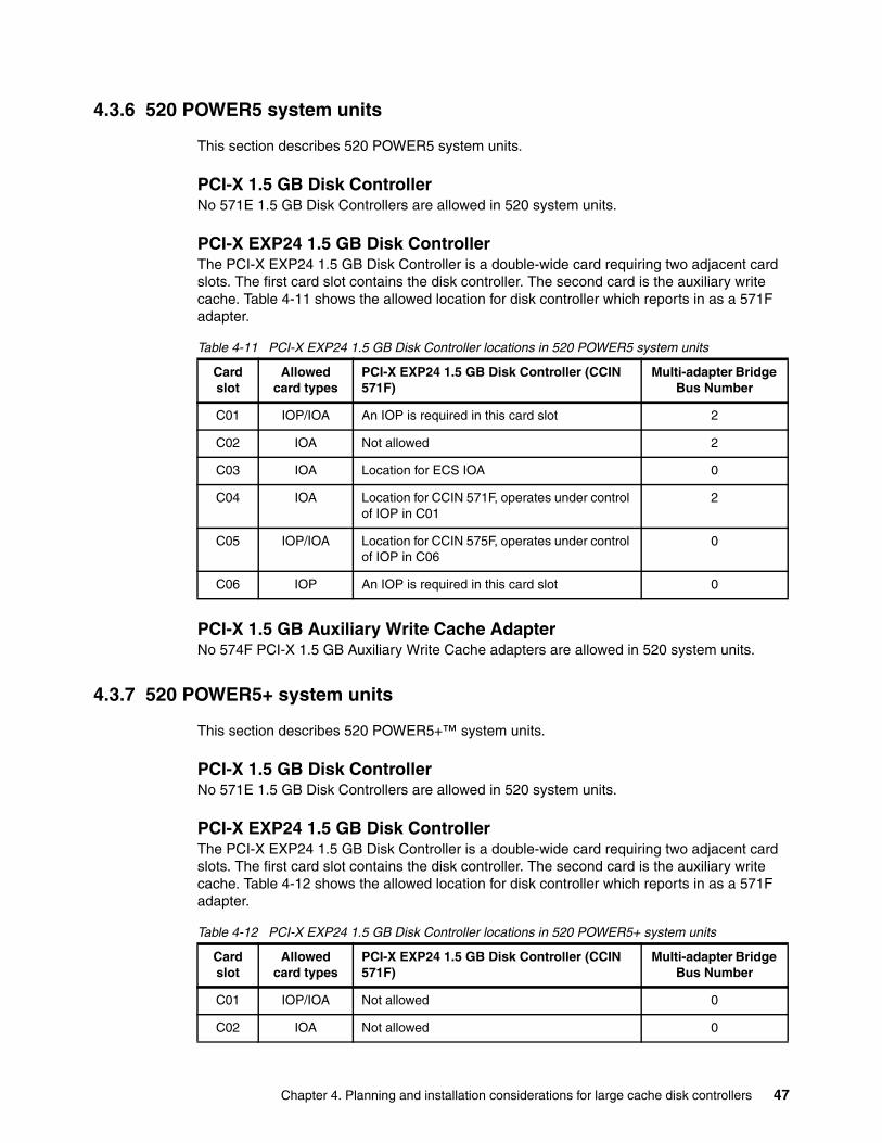
4.3.6 520 POWER5 system units
This section describes 520 POWER5 system units.
PCI-X 1.5 GB Disk ControllerNo 571E 1.5 GB Disk Controllers are allowed in 520 system units.
PCI-X EXP24 1.5 GB Disk ControllerThe PCI-X EXP24 1.5 GB Disk Controller is a double-wide card requiring two adjacent card slots. The first card slot contains the disk controller. The second card is the auxiliary write cache. Table 4-11 shows the allowed location for disk controller which reports in as a 571F adapter.
Table 4-11 PCI-X EXP24 1.5 GB Disk Controller locations in 520 POWER5 system units
PCI-X 1.5 GB Auxiliary Write Cache AdapterNo 574F PCI-X 1.5 GB Auxiliary Write Cache adapters are allowed in 520 system units.
4.3.7 520 POWER5+ system units
This section describes 520 POWER5+™ system units.
PCI-X 1.5 GB Disk ControllerNo 571E 1.5 GB Disk Controllers are allowed in 520 system units.
PCI-X EXP24 1.5 GB Disk ControllerThe PCI-X EXP24 1.5 GB Disk Controller is a double-wide card requiring two adjacent card slots. The first card slot contains the disk controller. The second card is the auxiliary write cache. Table 4-12 shows the allowed location for disk controller which reports in as a 571F adapter.
Table 4-12 PCI-X EXP24 1.5 GB Disk Controller locations in 520 POWER5+ system units
Card slot
Allowed card types
PCI-X EXP24 1.5 GB Disk Controller (CCIN 571F)
Multi-adapter Bridge Bus Number
C01 IOP/IOA An IOP is required in this card slot 2
C02 IOA Not allowed 2
C03 IOA Location for ECS IOA 0
C04 IOA Location for CCIN 571F, operates under control of IOP in C01
2
C05 IOP/IOA Location for CCIN 575F, operates under control of IOP in C06
0
C06 IOP An IOP is required in this card slot 0
Card slot
Allowed card types
PCI-X EXP24 1.5 GB Disk Controller (CCIN 571F)
Multi-adapter Bridge Bus Number
C01 IOP/IOA Not allowed 0
C02 IOA Not allowed 0
Chapter 4. Planning and installation considerations for large cache disk controllers 47
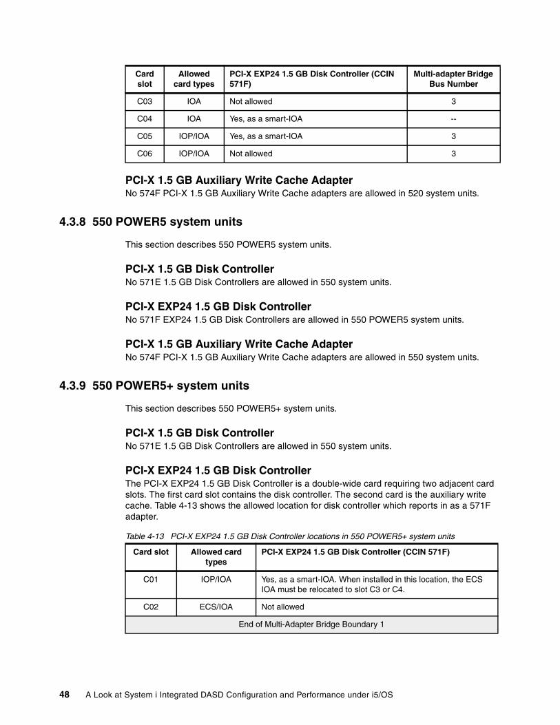
PCI-X 1.5 GB Auxiliary Write Cache AdapterNo 574F PCI-X 1.5 GB Auxiliary Write Cache adapters are allowed in 520 system units.
4.3.8 550 POWER5 system units
This section describes 550 POWER5 system units.
PCI-X 1.5 GB Disk ControllerNo 571E 1.5 GB Disk Controllers are allowed in 550 system units.
PCI-X EXP24 1.5 GB Disk ControllerNo 571F EXP24 1.5 GB Disk Controllers are allowed in 550 POWER5 system units.
PCI-X 1.5 GB Auxiliary Write Cache AdapterNo 574F PCI-X 1.5 GB Auxiliary Write Cache adapters are allowed in 550 system units.
4.3.9 550 POWER5+ system units
This section describes 550 POWER5+ system units.
PCI-X 1.5 GB Disk ControllerNo 571E 1.5 GB Disk Controllers are allowed in 550 system units.
PCI-X EXP24 1.5 GB Disk ControllerThe PCI-X EXP24 1.5 GB Disk Controller is a double-wide card requiring two adjacent card slots. The first card slot contains the disk controller. The second card is the auxiliary write cache. Table 4-13 shows the allowed location for disk controller which reports in as a 571F adapter.
Table 4-13 PCI-X EXP24 1.5 GB Disk Controller locations in 550 POWER5+ system units
C03 IOA Not allowed 3
C04 IOA Yes, as a smart-IOA --
C05 IOP/IOA Yes, as a smart-IOA 3
C06 IOP/IOA Not allowed 3
Card slot
Allowed card types
PCI-X EXP24 1.5 GB Disk Controller (CCIN 571F)
Multi-adapter Bridge Bus Number
Card slot Allowed card types
PCI-X EXP24 1.5 GB Disk Controller (CCIN 571F)
C01 IOP/IOA Yes, as a smart-IOA. When installed in this location, the ECS IOA must be relocated to slot C3 or C4.
C02 ECS/IOA Not allowed
End of Multi-Adapter Bridge Boundary 1
48 A Look at System i Integrated DASD Configuration and Performance under i5/OS
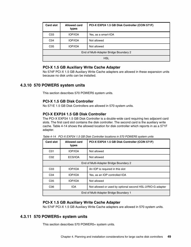
PCI-X 1.5 GB Auxiliary Write Cache AdapterNo 574F PCI-X 1.5 GB Auxiliary Write Cache adapters are allowed in these expansion units because no disk units can be installed.
4.3.10 570 POWER5 system units
This section describes 570 POWER5 system units.
PCI-X 1.5 GB Disk ControllerNo 571E 1.5 GB Disk Controllers are allowed in 570 system units.
PCI-X EXP24 1.5 GB Disk ControllerThe PCI-X EXP24 1.5 GB Disk Controller is a double-wide card requiring two adjacent card slots. The first card slot contains the disk controller. The second card is the auxiliary write cache. Table 4-14 shows the allowed location for disk controller which reports in as a 571F adapter.
Table 4-14 PCI-X EXP24 1.5 GB Disk Controller locations in 570 POWER5 system units
PCI-X 1.5 GB Auxiliary Write Cache AdapterNo 574F PCI-X 1.5 GB Auxiliary Write Cache adapters are allowed in 570 system units.
4.3.11 570 POWER5+ system units
This section describes 570 POWER5+ system units.
C03 IOP/IOA Yes, as a smart-IOA
C04 IOP/IOA Not allowed
C05 IOP/IOA Not allowed
End of Multi-Adapter Bridge Boundary 2
HSL
Card slot Allowed card types
PCI-X EXP24 1.5 GB Disk Controller (CCIN 571F)
Card slot Allowed card types
PCI-X EXP24 1.5 GB Disk Controller (CCIN 571F)
C01 IOP/IOA Not allowed
C02 ECS/IOA Not allowed
End of Multi-Adapter Bridge Boundary 2
C03 IOP/IOA An IOP is required in this slot
C04 IOP/IOA Yes, as an IOP controlled IOA
C05 IOP/IOA Not allowed
C06 IOA Not allowed or used by optional second HSL-2/RIO-G adapter
End of Multi-Adapter Bridge Boundary 1
Chapter 4. Planning and installation considerations for large cache disk controllers 49
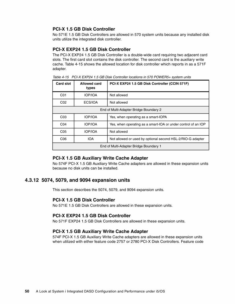
PCI-X 1.5 GB Disk ControllerNo 571E 1.5 GB Disk Controllers are allowed in 570 system units because any installed disk units utilize the integrated disk controller.
PCI-X EXP24 1.5 GB Disk ControllerThe PCI-X EXP24 1.5 GB Disk Controller is a double-wide card requiring two adjacent card slots. The first card slot contains the disk controller. The second card is the auxiliary write cache. Table 4-15 shows the allowed location for disk controller which reports in as a 571F adapter.
Table 4-15 PCI-X EXP24 1.5 GB Disk Controller locations in 570 POWER5+ system units
PCI-X 1.5 GB Auxiliary Write Cache AdapterNo 574F PCI-X 1.5 GB Auxiliary Write Cache adapters are allowed in these expansion units because no disk units can be installed.
4.3.12 5074, 5079, and 9094 expansion units
This section describes the 5074, 5079, and 9094 expansion units.
PCI-X 1.5 GB Disk ControllerNo 571E 1.5 GB Disk Controllers are allowed in these expansion units.
PCI-X EXP24 1.5 GB Disk ControllerNo 571F EXP24 1.5 GB Disk Controllers are allowed in these expansion units.
PCI-X 1.5 GB Auxiliary Write Cache Adapter574F PCI-X 1.5 GB Auxiliary Write Cache adapters are allowed in these expansion units when utilized with either feature code 2757 or 2780 PCI-X Disk Controllers. Feature code
Card slot Allowed card types
PCI-X EXP24 1.5 GB Disk Controller (CCIN 571F)
C01 IOP/IOA Not allowed
C02 ECS/IOA Not allowed
End of Multi-Adapter Bridge Boundary 2
C03 IOP/IOA Yes, when operating as a smart-IOPA
C04 IOP/IOA Yes, when operating as a smart-IOA or under control of an IOP
C05 IOP/IOA Not allowed
C06 IOA Not allowed or used by optional second HSL-2/RIO-G adapter
End of Multi-Adapter Bridge Boundary 1
50 A Look at System i Integrated DASD Configuration and Performance under i5/OS
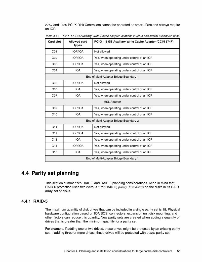
2757 and 2780 PCI-X Disk Controllers cannot be operated as smart-IOAs and always require an IOP.
Table 4-16 PCI-X 1.5 GB Auxiliary Write Cache adapter locations in 5074 and similar expansion units
4.4 Parity set planning
This section summarizes RAID-5 and RAID-6 planning considerations. Keep in mind that RAID-6 protection uses two (versus 1 for RAID-5) parity data bands on the disks in its RAID array set of disks.
4.4.1 RAID-5
The maximum quantity of disk drives that can be included in a single parity set is 18. Physical hardware configuration based on IOA SCSI connectors, expansion unit disk mounting, and other factors can reduce this quantity. New parity sets are created when adding a quantity of drives that is greater than the minimum quantity for a parity set.
For example, if adding one or two drives, these drives might be protected by an existing parity set. If adding three or more drives, these drives will be protected with a new parity set.
Card slot Allowed card types
PCI-X 1.5 GB Auxiliary Write Cache Adapter (CCIN 574F)
C01 IOP/IOA Not allowed
C02 IOP/IOA Yes, when operating under control of an IOP
C03 IOP/IOA Yes, when operating under control of an IOP
C04 IOA Yes, when operating under control of an IOP
End of Multi-Adapter Bridge Boundary 1
C05 IOP/IOA Not allowed
C06 IOA Yes, when operating under control of an IOP
C07 IOA Yes, when operating under control of an IOP
HSL Adapter
C09 IOP/IOA Yes, when operating under control of an IOP
C10 IOA Yes, when operating under control of an IOP
End of Multi-Adapter Bridge Boundary 2
C11 IOP/IOA Not allowed
C12 IOP/IOA Yes, when operating under control of an IOP
C13 IOA Yes, when operating under control of an IOP
C14 IOP/IOA Yes, when operating under control of an IOP
C15 IOA Yes, when operating under control of an IOP
End of Multi-Adapter Bridge Boundary 1
Chapter 4. Planning and installation considerations for large cache disk controllers 51
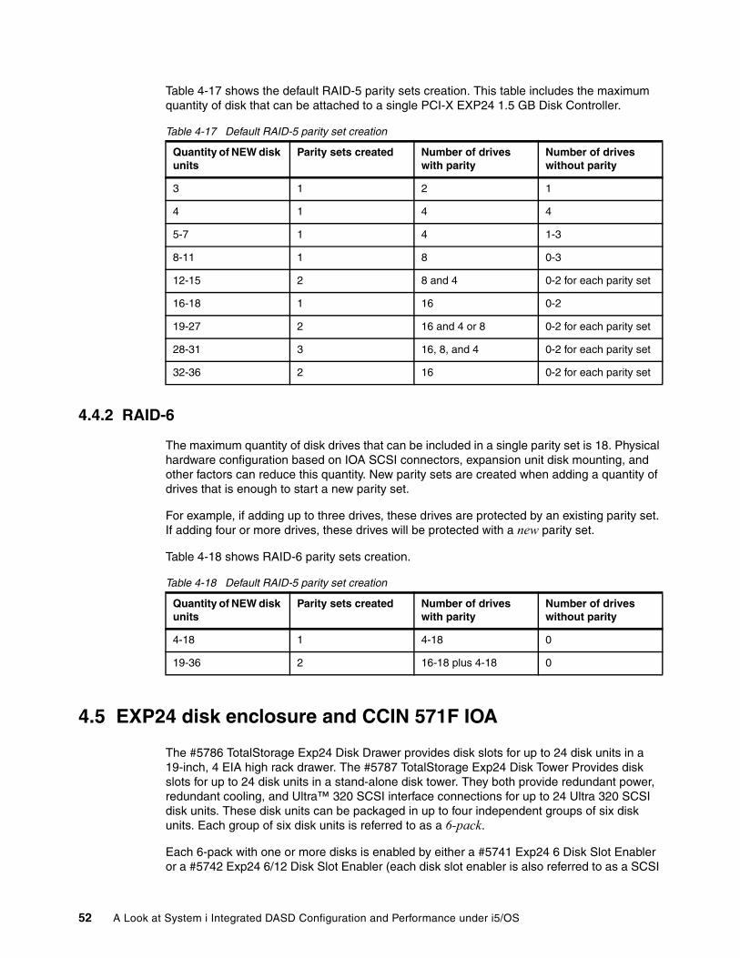
Table 4-17 shows the default RAID-5 parity sets creation. This table includes the maximum quantity of disk that can be attached to a single PCI-X EXP24 1.5 GB Disk Controller.
Table 4-17 Default RAID-5 parity set creation
4.4.2 RAID-6
The maximum quantity of disk drives that can be included in a single parity set is 18. Physical hardware configuration based on IOA SCSI connectors, expansion unit disk mounting, and other factors can reduce this quantity. New parity sets are created when adding a quantity of drives that is enough to start a new parity set.
For example, if adding up to three drives, these drives are protected by an existing parity set. If adding four or more drives, these drives will be protected with a new parity set.
Table 4-18 shows RAID-6 parity sets creation.
Table 4-18 Default RAID-5 parity set creation
4.5 EXP24 disk enclosure and CCIN 571F IOA
The #5786 TotalStorage Exp24 Disk Drawer provides disk slots for up to 24 disk units in a 19-inch, 4 EIA high rack drawer. The #5787 TotalStorage Exp24 Disk Tower Provides disk slots for up to 24 disk units in a stand-alone disk tower. They both provide redundant power, redundant cooling, and Ultra™ 320 SCSI interface connections for up to 24 Ultra 320 SCSI disk units. These disk units can be packaged in up to four independent groups of six disk units. Each group of six disk units is referred to as a 6-pack.
Each 6-pack with one or more disks is enabled by either a #5741 Exp24 6 Disk Slot Enabler or a #5742 Exp24 6/12 Disk Slot Enabler (each disk slot enabler is also referred to as a SCSI
Quantity of NEW disk units
Parity sets created Number of drives with parity
Number of drives without parity
3 1 2 1
4 1 4 4
5-7 1 4 1-3
8-11 1 8 0-3
12-15 2 8 and 4 0-2 for each parity set
16-18 1 16 0-2
19-27 2 16 and 4 or 8 0-2 for each parity set
28-31 3 16, 8, and 4 0-2 for each parity set
32-36 2 16 0-2 for each parity set
Quantity of NEW disk units
Parity sets created Number of drives with parity
Number of drives without parity
4-18 1 4-18 0
19-36 2 16-18 plus 4-18 0
52 A Look at System i Integrated DASD Configuration and Performance under i5/OS
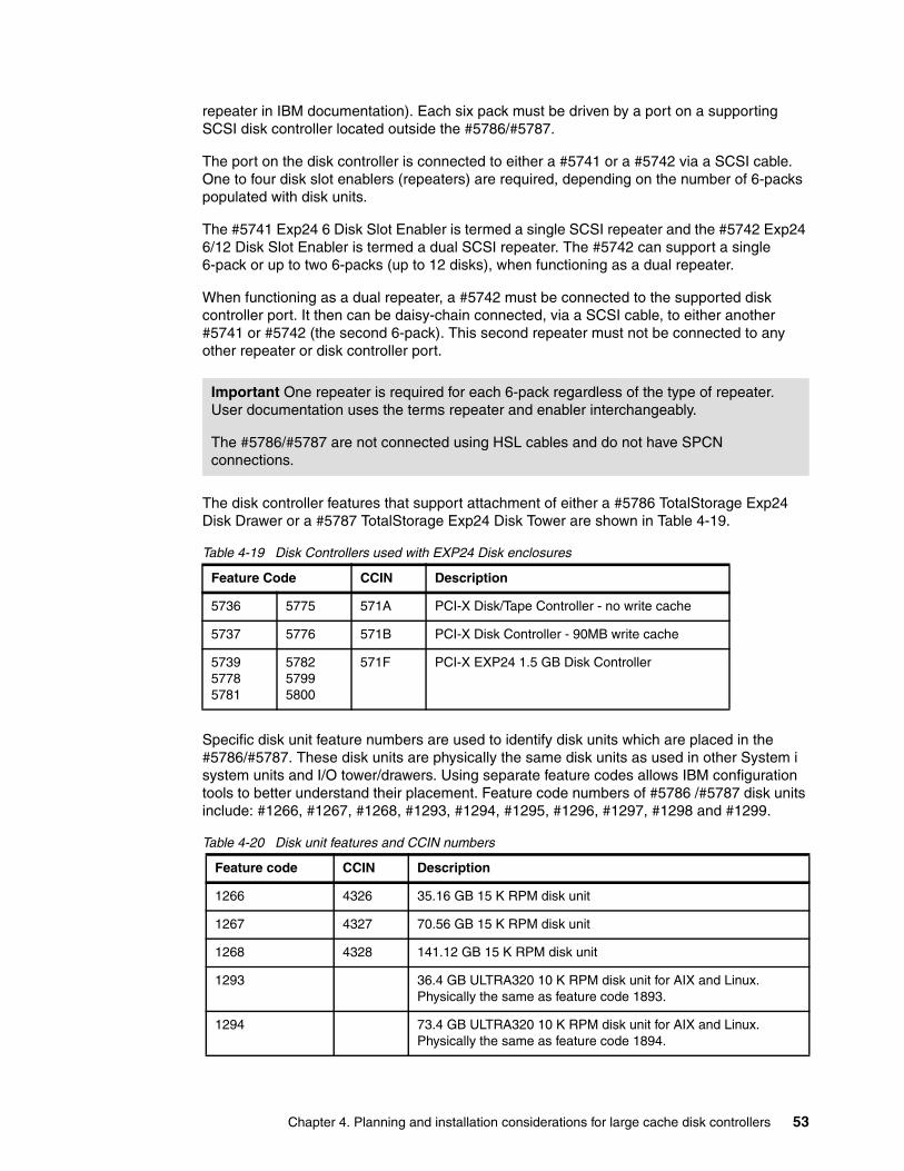
repeater in IBM documentation). Each six pack must be driven by a port on a supporting SCSI disk controller located outside the #5786/#5787.
The port on the disk controller is connected to either a #5741 or a #5742 via a SCSI cable. One to four disk slot enablers (repeaters) are required, depending on the number of 6-packs populated with disk units.
The #5741 Exp24 6 Disk Slot Enabler is termed a single SCSI repeater and the #5742 Exp24 6/12 Disk Slot Enabler is termed a dual SCSI repeater. The #5742 can support a single 6-pack or up to two 6-packs (up to 12 disks), when functioning as a dual repeater.
When functioning as a dual repeater, a #5742 must be connected to the supported disk controller port. It then can be daisy-chain connected, via a SCSI cable, to either another #5741 or #5742 (the second 6-pack). This second repeater must not be connected to any other repeater or disk controller port.
The disk controller features that support attachment of either a #5786 TotalStorage Exp24 Disk Drawer or a #5787 TotalStorage Exp24 Disk Tower are shown in Table 4-19.
Table 4-19 Disk Controllers used with EXP24 Disk enclosures
Specific disk unit feature numbers are used to identify disk units which are placed in the #5786/#5787. These disk units are physically the same disk units as used in other System i system units and I/O tower/drawers. Using separate feature codes allows IBM configuration tools to better understand their placement. Feature code numbers of #5786 /#5787 disk units include: #1266, #1267, #1268, #1293, #1294, #1295, #1296, #1297, #1298 and #1299.
Table 4-20 Disk unit features and CCIN numbers
Important One repeater is required for each 6-pack regardless of the type of repeater. User documentation uses the terms repeater and enabler interchangeably.
The #5786/#5787 are not connected using HSL cables and do not have SPCN connections.
Feature Code CCIN Description
5736 5775 571A PCI-X Disk/Tape Controller - no write cache
5737 5776 571B PCI-X Disk Controller - 90MB write cache
573957785781
578257995800
571F PCI-X EXP24 1.5 GB Disk Controller
Feature code CCIN Description
1266 4326 35.16 GB 15 K RPM disk unit
1267 4327 70.56 GB 15 K RPM disk unit
1268 4328 141.12 GB 15 K RPM disk unit
1293 36.4 GB ULTRA320 10 K RPM disk unit for AIX and Linux. Physically the same as feature code 1893.
1294 73.4 GB ULTRA320 10 K RPM disk unit for AIX and Linux. Physically the same as feature code 1894.
Chapter 4. Planning and installation considerations for large cache disk controllers 53
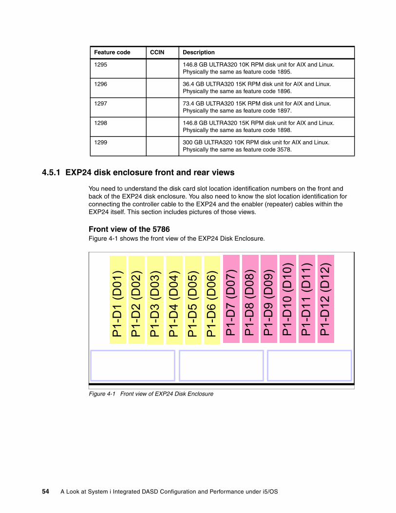
4.5.1 EXP24 disk enclosure front and rear views
You need to understand the disk card slot location identification numbers on the front and back of the EXP24 disk enclosure. You also need to know the slot location identification for connecting the controller cable to the EXP24 and the enabler (repeater) cables within the EXP24 itself. This section includes pictures of those views.
Front view of the 5786Figure 4-1 shows the front view of the EXP24 Disk Enclosure.
Figure 4-1 Front view of EXP24 Disk Enclosure
1295 146.8 GB ULTRA320 10K RPM disk unit for AIX and Linux. Physically the same as feature code 1895.
1296 36.4 GB ULTRA320 15K RPM disk unit for AIX and Linux. Physically the same as feature code 1896.
1297 73.4 GB ULTRA320 15K RPM disk unit for AIX and Linux. Physically the same as feature code 1897.
1298 146.8 GB ULTRA320 15K RPM disk unit for AIX and Linux. Physically the same as feature code 1898.
1299 300 GB ULTRA320 10K RPM disk unit for AIX and Linux. Physically the same as feature code 3578.
Feature code CCIN Description
P1-D
1 (D
01)
P1-D
2 (D
02)
P1-
D3
(D03
)P
1-D
4 (D
04)
P1-D
5 (D
05)
P1-
D6
(D06
)P
1-D
7 (D
07)
P1-
D8
(D08
)P
1-D
9 (D
09)
P1-
D10
(D10
)P1
-D11
(D11
)P
1-D
12 (D
12)
P1-D
1 (D
01)
P1-D
2 (D
02)
P1-
D3
(D03
)P
1-D
4 (D
04)
P1-D
5 (D
05)
P1-
D6
(D06
)
P1-D
1 (D
01)
P1-D
2 (D
02)
P1-
D3
(D03
)P
1-D
4 (D
04)
P1-D
5 (D
05)
P1-
D6
(D06
)P
1-D
7 (D
07)
P1-
D8
(D08
)P
1-D
9 (D
09)
P1-
D10
(D10
)P1
-D11
(D11
)P
1-D
12 (D
12)
P1-
D7
(D07
)P
1-D
8 (D
08)
P1-
D9
(D09
)P
1-D
10 (D
10)
P1-D
11 (D
11)
P1-
D12
(D12
)
54 A Look at System i Integrated DASD Configuration and Performance under i5/OS
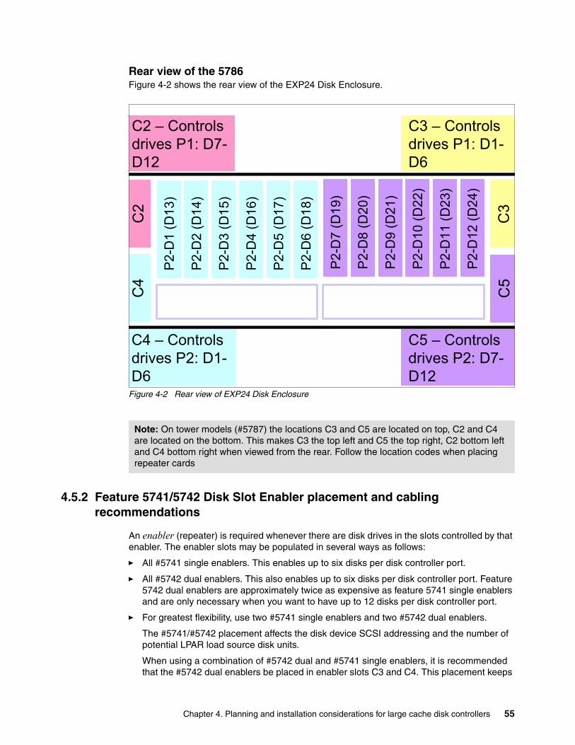
Rear view of the 5786Figure 4-2 shows the rear view of the EXP24 Disk Enclosure.
Figure 4-2 Rear view of EXP24 Disk Enclosure
4.5.2 Feature 5741/5742 Disk Slot Enabler placement and cabling recommendations
An enabler (repeater) is required whenever there are disk drives in the slots controlled by that enabler. The enabler slots may be populated in several ways as follows:
� All #5741 single enablers. This enables up to six disks per disk controller port.
� All #5742 dual enablers. This also enables up to six disks per disk controller port. Feature 5742 dual enablers are approximately twice as expensive as feature 5741 single enablers and are only necessary when you want to have up to 12 disks per disk controller port.
� For greatest flexibility, use two #5741 single enablers and two #5742 dual enablers.
The #5741/#5742 placement affects the disk device SCSI addressing and the number of potential LPAR load source disk units.
When using a combination of #5742 dual and #5741 single enablers, it is recommended that the #5742 dual enablers be placed in enabler slots C3 and C4. This placement keeps
Note: On tower models (#5787) the locations C3 and C5 are located on top, C2 and C4 are located on the bottom. This makes C3 the top left and C5 the top right, C2 bottom left and C4 bottom right when viewed from the rear. Follow the location codes when placing repeater cards
C2 – Controls drives P1: D7-D12
C3 – Controls drives P1: D1-D6
C4 – Controls drives P2: D1-D6
C5 – Controls drives P2: D7-D12
P2-
D7
(D19
)
P2-
D8
(D20
)
P2-
D9
(D21
)
P2-
D10
(D22
)
P2-
D11
(D23
)
P2-
D12
(D24
)
C4
C2
C5
C3
P2-
D1
(D13
)
P2-
D2
(D14
)
P2-
D3
(D15
)
P2-
D4
(D16
)
P2-
D5
(D17
)
P2-
D6
(D18
)
C2 – Controls drives P1: D7-D12
C3 – Controls drives P1: D1-D6
C4 – Controls drives P2: D1-D6
C5 – Controls drives P2: D7-D12
P2-
D7
(D19
)
P2-
D8
(D20
)
P2-
D9
(D21
)
P2-
D10
(D22
)
P2-
D11
(D23
)
P2-
D12
(D24
)
P2-
D7
(D19
)
P2-
D8
(D20
)
P2-
D9
(D21
)
P2-
D10
(D22
)
P2-
D11
(D23
)
P2-
D12
(D24
)
C4
C2
C5
C3
P2-
D1
(D13
)
P2-
D2
(D14
)
P2-
D3
(D15
)
P2-
D4
(D16
)
P2-
D5
(D17
)
P2-
D6
(D18
)
P2-
D1
(D13
)
P2-
D2
(D14
)
P2-
D3
(D15
)
P2-
D4
(D16
)
P2-
D5
(D17
)
P2-
D6
(D18
)
Chapter 4. Planning and installation considerations for large cache disk controllers 55
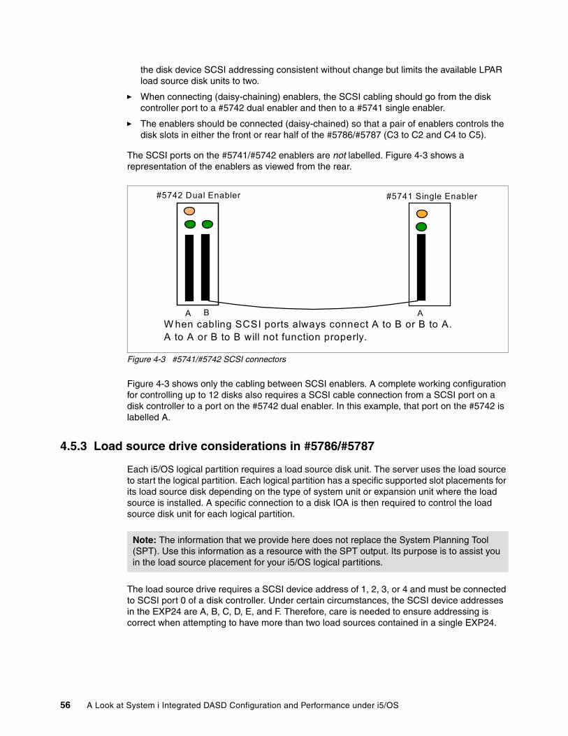
the disk device SCSI addressing consistent without change but limits the available LPAR load source disk units to two.
� When connecting (daisy-chaining) enablers, the SCSI cabling should go from the disk controller port to a #5742 dual enabler and then to a #5741 single enabler.
� The enablers should be connected (daisy-chained) so that a pair of enablers controls the disk slots in either the front or rear half of the #5786/#5787 (C3 to C2 and C4 to C5).
The SCSI ports on the #5741/#5742 enablers are not labelled. Figure 4-3 shows a representation of the enablers as viewed from the rear.
Figure 4-3 #5741/#5742 SCSI connectors
Figure 4-3 shows only the cabling between SCSI enablers. A complete working configuration for controlling up to 12 disks also requires a SCSI cable connection from a SCSI port on a disk controller to a port on the #5742 dual enabler. In this example, that port on the #5742 is labelled A.
4.5.3 Load source drive considerations in #5786/#5787
Each i5/OS logical partition requires a load source disk unit. The server uses the load source to start the logical partition. Each logical partition has a specific supported slot placements for its load source disk depending on the type of system unit or expansion unit where the load source is installed. A specific connection to a disk IOA is then required to control the load source disk unit for each logical partition.
The load source drive requires a SCSI device address of 1, 2, 3, or 4 and must be connected to SCSI port 0 of a disk controller. Under certain circumstances, the SCSI device addresses in the EXP24 are A, B, C, D, E, and F. Therefore, care is needed to ensure addressing is correct when attempting to have more than two load sources contained in a single EXP24.
A B
#5742 Dual Enabler
A
#5741 Single Enabler
W hen cabling SCSI ports always connect A to B or B to A.A to A or B to B will not function properly.
Note: The information that we provide here does not replace the System Planning Tool (SPT). Use this information as a resource with the SPT output. Its purpose is to assist you in the load source placement for your i5/OS logical partitions.
56 A Look at System i Integrated DASD Configuration and Performance under i5/OS
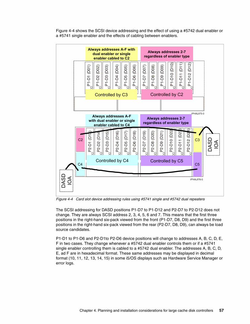
Figure 4-4 shows the SCSI device addressing and the effect of using a #5742 dual enabler or a #5741 single enabler and the effects of cabling between enablers.
Figure 4-4 Card slot device addressing rules using #5741 single and #5742 dual repeaters
The SCSI addressing for DASD positions P1-D7 to P1-D12 and P2-D7 to P2-D12 does not change. They are always SCSI address 2, 3, 4, 5, 6 and 7. This means that the first three positions in the right-hand six-pack viewed from the front (P1-D7, D8, D9) and the first three positions in the right-hand six-pack viewed from the rear (P2-D7, D8, D9), can always be load source candidates.
P1-D1 to P1-D6 and P2-D1to P2-D6 device positions will change to addresses A, B, C, D, E, F in two cases. They change whenever a #5742 dual enabler controls them or if a #5741 single enabler controlling them is cabled to a #5742 dual enabler. The addresses A, B, C, D, E, ad F are in hexadecimal format. These same addresses may be displayed in decimal format (10, 11, 12, 13, 14, 15) in some i5/OS displays such as Hardware Service Manager or error logs.
Controlled by C4 Controlled by C5
C2 C3
C4 C5
Controlled by C2Controlled by C3
Always addresses A-F with dual enabler or single enabler cabled to C2
Always addresses 2-7 regardless of enabler type
Always addresses A-F with dual enabler or single
enabler cabled to C4
Always addresses 2-7 regardless of enabler type
DA
SD
IOA
DA
SD
IOA
Chapter 4. Planning and installation considerations for large cache disk controllers 57
Load source rules for #5786 and #5787Load source rules include:
� The load source disk must be controlled by the SCSI bus port 0 of the load source disk unit controller.
� P1-D1, P1-D2, or P1-D3 can contain the load source disk only if slot C3 contains a #5741 single enabler card that is connected to SCSI port 0 of the disk controller.
� P1-D7, P1-D8, or P1-D9 can contain the load source if the #5741 in C2 is connected to SCSI port 0 on the disk controller or if the #5741 in C2 is cabled to the #5742 dual enabler in C3 and the #5742 in C3 is connected to SCSI port 0 on the disk controller.
� P2-D1, P2-D2, or P2-D3 can contain the load source disk only if slot C4 contains a #5741 single enabler card that is connected to SCSI port 0 of the disk controller.
� P2-D7, P2-D8, or P2-D9 can contain the load source if the #5741 in C5 is connected to SCSI port 0 on the disk controller or if the #5741 in C5 is cabled to the #5742 dual enabler in C4 and the #5742 in C4 is connected to SCSI port 0 on the disk controller.
#5741 and #5742 SCSI repeater card placement recommendationsRepeater card placement recommendations include:
� To have four load source disks available in a single #5786/#5787, the #5786/#5787 should contain four #5741 single enablers or #5742 dual enablers in C2 and C5 and #5741 single enablers in C3 and C4.
� To keep SCSI addressing consistent with no changes but limit the available load source disks to two instead of four, then the #5786/#5787 should have #5741 single enablers in C2 and C5, and #5742 dual enablers in C3 and C4.
� When daisy-chaining SCSI enablers, connect C2 to C3 and connect C5 to C4. This way, the enablers in C2 and C3 will control the disks in the front of the #5786/#5787 and the enablers in C4 and C5 will control the disks in the rear.
58 A Look at System i Integrated DASD Configuration and Performance under i5/OS
Chapter 5. Performance considerations
This chapter provides a summary of performance comparisons among the #2780 disk controller (IOA), the previously faster integrated disk controller support under i5/OS with the larger 1.5 GB write cache controllers announced. RAID versus mirroring and RAID-5 versus RAID-6 comparisons are made. The test results shown are from the January 2007 and 2008 versions of the Performance Capabilities Reference manual.
Expanded performance information is included in:
� Appendix C., “Understanding RAID-5, RAID-6, and associated performance considerations” on page 73
� Appendix D., “Mirroring” on page 85
� Appendix G., “A real-world approach to sizing disks for adequate performance” on page 101
5
© Copyright IBM Corp. 2008. All rights reserved. 59
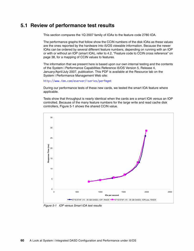
5.1 Review of performance test results
This section compares the 1Q 2007 family of IOAs to the feature code 2780 IOA.
The performance graphs that follow show the CCIN numbers of the disk IOAs as these values are the ones reported by the hardware into i5/OS viewable information. Because the newer IOAs can be ordered by several different feature numbers, depending on running with an IOP or with or without an IOP (smart IOA), refer to 4.2, “Feature code to CCIN cross reference” on page 38, for a mapping of CCIN values to features.
The information that we present here is based upon our own internal testing and the contents of the System i Performance Capabilities Reference i5/OS Version 5, Release 4, January/April/July 2007, publication. This PDF is available at the Resource tab on the System i Performance Management Web site:
http://www.ibm.com/eserver/iseries/perfmgmt
During our performance tests of these new cards, we tested the smart IOA feature where applicable.
Tests show that throughput is nearly identical when the cards are a smart IOA versus an IOP controlled. Because of the many feature numbers for the large write and read cache disk controllers, Figure 5-1 shows the shared CCIN value.
Figure 5-1 IOP versus Smart IOA test results
0
5
10
15
20
25
30
35
0 500 1000 1500 2000 2500
IOs per second
Res
pons
e Ti
me
(ms)
571E/574F (15 - 35 GB DASD): IOP, RAID5 571E/574F (15 - 35 GB DASD): IOPLess, RAID5
60 A Look at System i Integrated DASD Configuration and Performance under i5/OS
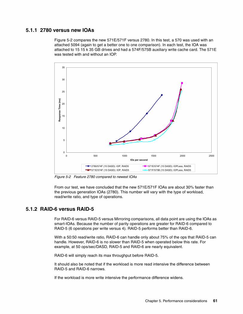
5.1.1 2780 versus new IOAs
Figure 5-2 compares the new 571E/571F versus 2780. In this test, a 570 was used with an attached 5094 (again to get a better one to one comparison). In each test, the IOA was attached to 15 15 k 35 GB drives and had a 574F/575B auxiliary write cache card. The 571E was tested with and without an IOP.
Figure 5-2 Feature 2780 compared to newest IOAs
From our test, we have concluded that the new 571E/571F IOAs are about 30% faster than the previous generation IOAs (2780). This number will vary with the type of workload, read/write ratio, and type of operations.
5.1.2 RAID-6 versus RAID-5
For RAID-6 versus RAID-5 versus Mirroring comparisons, all data point are using the IOAs as smart-IOAs. Because the number of parity operations are greater for RAID-6 compared to RAID-5 (6 operations per write versus 4). RAID-5 performs better than RAID-6.
With a 50:50 read/write ratio, RAID-6 can handle only about 75% of the ops that RAID-5 can handle. However, RAID-6 is no slower than RAID-5 when operated below this rate. For example, at 50 ops/sec/DASD, RAID-5 and RAID-6 are nearly equivalent.
RAID-6 will simply reach its max throughput before RAID-5.
It should also be noted that if the workload is more read intensive the difference between RAID-5 and RAID-6 narrows.
If the workload is more write intensive the performance difference widens.
0
5
10
15
20
25
30
35
0 500 1000 1500 2000 2500
IOs per second
Res
pons
e Ti
me
(ms)
2780/574F (15 DASD): IOP, RAID5 571E/574F (15 DASD): IOPLess, RAID5571E/574F (15 DASD): IOP, RAID5 571F/575B (15 DASD): IOPLess, RAID5
Chapter 5. Performance considerations 61
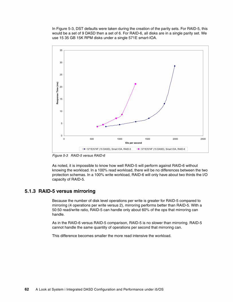
In Figure 5-3, DST defaults were taken during the creation of the parity sets. For RAID-5, this would be a set of 9 DASD then a set of 6. For RAID-6, all disks are in a single parity set. We use 15 35 GB 15K RPM disks under a single 571E smart-IOA.
Figure 5-3 RAID-5 versus RAID-6
As noted, it is impossible to know how well RAID-5 will perform against RAID-6 without knowing the workload. In a 100% read workload, there will be no differences between the two protection schemas. In a 100% write workload, RAID-6 will only have about two thirds the I/O capacity of RAID-5.
5.1.3 RAID-5 versus mirroring
Because the number of disk level operations per write is greater for RAID-5 compared to mirroring (4 operations per write versus 2), mirroring performs better than RAID-5. With a 50:50 read/write ratio, RAID-5 can handle only about 60% of the ops that mirroring can handle.
As in the RAID-6 versus RAID-5 comparison, RAID-5 is no slower than mirroring. RAID-5 cannot handle the same quantity of operations per second that mirroring can.
This difference becomes smaller the more read intensive the workload.
0
5
10
15
20
25
30
35
0 500 1000 1500 2000 2500
IOs per second
Res
pons
e Ti
me
(ms)
571E/574F (15 DASD), Smart IOA, RAID-5 571E/574F (15 DASD), Smart IOA, RAID-6
62 A Look at System i Integrated DASD Configuration and Performance under i5/OS
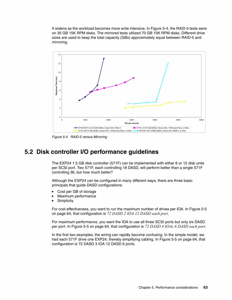
It widens as the workload becomes more write intensive. In Figure 5-4, the RAID-5 tests were on 35 GB 15K RPM disks. The mirrored tests utilized 70 GB 15K RPM disks. Different drive sizes are used to keep the total capacity (GBs) approximately equal between RAID-5 and mirroring.
Figure 5-4 RAID-5 versus Mirroring
5.2 Disk controller I/O performance guidelines
The EXP24 1.5 GB disk controller (571F) can be implemented with either 6 or 12 disk units per SCSI port. Two 571F, each controlling 18 DASD, will perform better than a single 571F controlling 36, but how much better?
Although the EXP24 can be configured in many different ways, there are three basic principals that guide DASD configurations:
� Cost per GB of storage� Maximum performance� Simplicity
For cost effectiveness, you want to run the maximum number of drives per IOA. In Figure 5-5 on page 64, that configuration is 72 DASD 2 IOA 12 DASD each port.
For maximum performance, you want the IOA to use all three SCSI ports but only six DASD per port. In Figure 5-5 on page 64, that configuration is 72 DASD 4 IOAs 6 DASD each port.
In the first two examples, the wiring can rapidly become confusing. In the simple model, we had each 571F drive one EXP24, thereby simplifying cabling. In Figure 5-5 on page 64, that configuration is 72 DASD 3 IOA 12 DASD 6 ports.
0
2
4
6
8
10
12
14
0 1000 2000 3000 4000 5000 6000
IOs per second
Res
pons
e Ti
me
(ms)
571E/574F (15-35 GB DASD), Smart IOA, RAID-5 571E (14-70 GB DASD), Smart IOA, 7 Mirrored Pairs, 2 IOAs571E (30-70 GB DASD): Smart IOA, 15 Mirrored Pairs, 2 IOAs 571E/574F (30-70GB DASD), Smart IOA, RAID-5, 2 IOAs
Chapter 5. Performance considerations 63
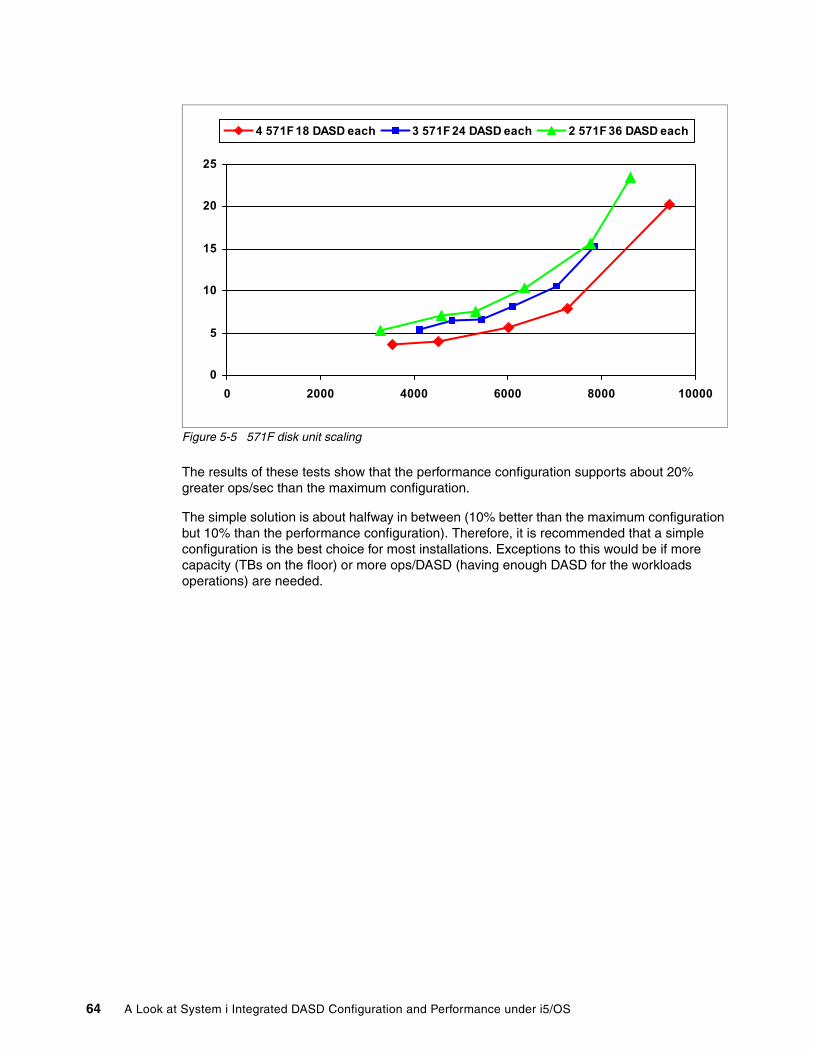
Figure 5-5 571F disk unit scaling
The results of these tests show that the performance configuration supports about 20% greater ops/sec than the maximum configuration.
The simple solution is about halfway in between (10% better than the maximum configuration but 10% than the performance configuration). Therefore, it is recommended that a simple configuration is the best choice for most installations. Exceptions to this would be if more capacity (TBs on the floor) or more ops/DASD (having enough DASD for the workloads operations) are needed.
0
5
10
15
20
25
0 2000 4000 6000 8000 10000
4 571F 18 DASD each 3 571F 24 DASD each 2 571F 36 DASD each
64 A Look at System i Integrated DASD Configuration and Performance under i5/OS
Appendix A. System i integrated disk capabilities that require a SAN on other systems
To obtain the sophistication of the storage subsystem that is provided by System i, most UNIX®, Linux, and PC-based systems require a SAN (and usually also virtualization software). This appendix lists the functions that are available with both SAN and System i functionality.
A
© Copyright IBM Corp. 2008. All rights reserved. 65
SAN and native System i capabilities
The functions listed in this section are available with both SAN and native System i approaches.
Read cache With System i, this capability is available at two levels:
� The system level� The disk controllers
The System i approach is arguably the most sophisticated read cache in the marketplace. Anything in main storage can be used by any program in the LPAR (providing that it has security clearance). The unique function is that sections of main storage can be segmented so that data brought in by one subsystem is not overwritten by another subsystem. (If data has been pre-fetched for batch processing, we do not want the interactive workload overlaying those pages before they can be used.)
Disk controllers provide the second level. Some controllers provide up to 1.6 GB of read cache which is used the same way SAN-based read cache is used. However, unlike generic SAN caches, it uses algorithms designed to complement the cache effect of single level storage and the disk’s read-ahead cache. It is also optimized to favor retaining data from random disk accesses.
Another key difference is that as controllers are added, the amount of read cache increases. In the i5/OS environment (and in virtual disk environments for AIX/Linux/attached PCs), the controller read caches can essentially be thought of as an L2 cache to the (usually larger) System i main memory. The easy accesses are usually satisfied within main memory, so the cache effectiveness is not as great as on other platforms without system self-caching capabilities.
Write cacheEach RAID-capable controller has a write-cache that can contain up to 1.5 GB of data being staged to be written to disk. Again, as additional controllers are added, the amount of available write cache increases. See Appendix B, “Understanding disk write cache” on page 69 for additional information about System i write cache and how it differs from write buffers.
Data spreadingSystem i and its predecessors have provided data spreading (for over 25 years) across all the drives in each Auxiliary Storage Pool (ASP). This usually results in far greater spreading (and therefore fewer hot-spots than the spreading typically occurring in SAN systems (where each logical disk unit (LUN) is usually spread across seven or eight disks, sometimes fewer). Not only is the data spread across drives, but i5/OS functions allow automatic database table extensions without users needing to manage to process.
Hot add of disk drives and entire towers of disksDisks be added to provide dynamic disk growth, and each database table (file) can grow without needing user management. Unlike most environments where entire RAID-5 or
Note: In some random access environments or if not using i5/OS-based virtual disk in AIX or Linux environments, the controller-based cache can be very useful.
66 A Look at System i Integrated DASD Configuration and Performance under i5/OS
RAID-6 arrays must be added, i5/OS allows RAID-5 or RAID-6 arrays to be increase by a single disk.
This approach is similar to SANs where a single logical disk can be added to an environment (but when disks are physically added to the SAN, it is usually an entire RAID array’s worth of drives).
Graphical disk management For most customers, the System i microcode and i5/OS itself perform necessary disk management automatically. The customer usually does not need to manage the disks and what data is placed on them. There are, however, strong graphical tools available for customers who want to manage their disk subsystems. While you can use these tools for an integrated disk configuration, some additional disk management is a requirement for SAN-attached disks (external disks) using disk management tools that are associated with the SAN storage product. These tools are not provided with the i5/OS and associated microcode.
Graphical and lightpath diagnostics The System i Navigator functions are further enhanced with problem determination capabilities that include pictograms of the disk enclosures. If a problem arises, the failing device is highlighted on the pictogram. Physical lights in the enclosure also help show which device is failing. These kinds of capabilities usually require a SAN.
Approaches to reducing backup WindowsSANs often use copy-based software to try to reduce backup windows. Even with this approach, the customer usually needs to temporarily stop (quiesce) the system to ensure the various databases (files) are synchronized with each other. You do not want to save a master file now and a corresponding item master file (that is continued to be updated as orders come in fifteen minutes later because the two files would be out of sync.
If you use journaling with commitment control, the system quiesce might not be required. Otherwise, the copy-based approach might have hidden considerations, which are not usually discussed during the sales process. Alternatively, the System i provides native capabilities to reduce backup windows, including Save-While-Active (no charge software), virtual tape capabilities (built into V5R4 of i5/OS), and High Availability Business Partner (HABP) software offerings from several vendors.
Disaster recovery and high availability approaches Disaster recovery should technically mean off-site capabilities for failover and might or might not have an associated time for recovery back to an operational state.
High availability has two components: Planned and Unplanned outages. You need to be sure of the capabilities that you want or need to address. Planned outages include backups and hardware and software upgrades. Unplanned outages are just what they imply and might be caused by hardware, software, or operational (people) errors. In the event of an unplanned outage, High availability usually implies a relatively rapid cadaver time to the secondary or backup system. You should examine SAN-based copy solutions carefully as they relate to high availability. While they might be able to accommodate a reduction in backup windows,
Note: SAN vendors often also talk about dynamic removal of logical disks. If a System i is attached to a SAN and the SAN operator attempts to remove a disk without first deallocating it on the System i, a system reload (of the LPAR) is usually required.
Appendix A. System i integrated disk capabilities that require a SAN on other systems 67
unless they are implemented using Independent Auxiliary Storage Pools, they have little ability to assist during software upgrades (operating system or application code).
From an unplanned outage perspective, SAN-based copy solutions usually require an IPL of the secondary system before the role-swap is accomplished. If the outage was unexpected, there could be damaged objects or improperly closed files that lead to an extended abnormal IPL. Alternatively, HABP software (which can be used in conjunction with SAN storage) provides solutions for Disaster Recovery as well as planned and unplanned downtime. An IPL is usually not required, so cutover can be rapid. Damaged objects on the primary machine are not an issue because the secondary machine has a duplicate set of objects. Cutover can be rapid. In fact, depending on the application code being used and the specific HABP software, this approach can provide application resiliency as well as data resiliency.
In addition to the HABP software, System i also has Cross-site Mirroring which provides functionality similar to SAN-based remote copy functions. For more information about cross-site mirroring, see section 5.3 in Data Resilience Solutions for IBM i5/OS High Availability Clusters available on the Web at:
http://www.redbooks.ibm.com/redpapers/pdfs/redp0888.pdf
Conclusion
If you are comparing System i integrated (also known as native or internal) disk with non-SAN disk subsystems on other platforms, you need to recognize the functionality provided by the i5/OS is similar to that of a SAN and the other subsystem would likely need a SAN to receive similar functionality. Thus, compared to the advantages a SAN provides for other platforms, the additional functionality will not be as extensive in i5/OS environments. While performance usually improves on other platforms when a SAN is added, integrated disks on the System i usually outperform external storage (due to the additional components required, the additional fabric and interfaces in the data path, and the additional path lengths for the software running in the storage server).
Also realize that some SAN vendors or products may initially present a price based on very large disks (up to 500 GB) that run at 10 k rpm (and sometimes even less). While such approaches might be viable for virtual tape solutions or historical data, they are unlikely to provide the performance needed in a production environment. Make sure when evaluating a SAN, that there are sufficient PHYSICAL disks of appropriate size and speed (15 k rpm recommended) to provide like-to-like comparisons with System i integrated disk offerings.
68 A Look at System i Integrated DASD Configuration and Performance under i5/OS
Appendix B. Understanding disk write cache
All RAID-capable System i disk controllers support write cache, which allows the disk controller to signal to the system that the disk write is complete as soon as the data is stored in the cache. The actual destaging of the data to the disks can then take place asynchronously. The newer faster controllers such as the #2780 and the disk controllers announced in February 2007 with 1.5 GB write cache that support #5094/5294 towers and EXP24 enclosures also include removable cache or an auxiliary write cache feature (optional with #2780 and the new 1.5 GB controller used with towers and standard for the new controllers supporting the EXP24).
The auxiliary write cache provides a second, mirrored copy of the cache. This mirrored copy of cache is a required feature for new purchases of controllers that will be used in a RAID-5 or RAID-6 environment and is also recommended if the controller will be used in a disk level (not controller level or higher) mirrored environment. The reason for this requirement is that in the event of a disk controller failure, the disk controller and the cache on that controller might need to be replaced. With the separate auxiliary write cache, after the failing controller is replaced, the cache can usually be restored, thus avoiding a potential system, LPAR, or Independent Auxiliary Storage Pool (IASP) reload.
However, the write cache is more than just a way of turning synchronous disk writes into asynchronous operations. It is a true cache, not just a write buffer (which is often incorrectly referred to as a write cache). As such, it can combine and eliminate physical disk writes. This can be especially important in a RAID-5 or RAID-6 environment where each logical disk write results in multiple physical disk activities (four disk actions for RAID-5, six disk actions for RAID-6). See Appendix C, “Understanding RAID-5, RAID-6, and associated performance considerations” on page 73 for more information.
Unlike a write buffer that has a one-to-one association of writes to the cache with writes to the disk, the write cache works as a true cache to eliminate duplicate writes. Programming techniques that are used in a data update situation may do one write to remove a lock on a record (for instance, while a screen requiring user input is displayed), then a second write to actually update the data (after the user has made the needed changes). With a write cache, the first write is essentially overwritten by the second write, and if the disks are busy, the first write might not need to physically occur. Also, if multiple sequential records on a disk are being updated, it is not necessary to write every record one at a time, but instead, the cache can combine those records into a single longer write. In fact, the controller even makes use of
B
© Copyright IBM Corp. 2008. All rights reserved. 69
a hardware assist unique to the System i called skip-on-write where sequential records that have not been updated are skipped over during a single write. The skip-on-write approach was originally put in place years ago (in conjunction with skip-on-read) to help with a function called swapping the Process Access Group (PAG), but it now provides benefits to the cached write process.
When the system writes data to the disk subsystem, it is first stored in pages in the disk controller cache.
Instead of immediately writing the data, it remains in cache for a short time. If the data is actively overwritten, it continues to remain in the cache until one of three things occurs to force the data to the disk:
� First, if a timer limit has been reached, the data is physically written. The amount of time it remains in cache is dependent on a number of factors, including the physical disk activity level.
� Second, if the write cache area is needed for other data and the specific data has not been recently updated, it is physically written (to free up the space).
� Third, and this is the interesting one, when the controller needs to physically write data to disk, it first examines the cache tables to determine if there is other data that would be relatively contiguous when physically written to disk (that is, it could be written without additional disk arm movement and very little additional disk rotational time). In this case, more data is written to disk with a single set of disk write commands from the disk controller and the skip-on-write capability can bypass data on the disks that is not being changed. The data that has been written is then flagged in the controller cache tables as being already written and is therefore overlayable by other data coming into the cache. It is a very efficient approach that is very analogous to the way read caches work.
Write cache overrunsWhile the size of today’s write cache usually minimizes the likelihood of write cache overruns, they can still occur. This happens when the amount of data being written and the workload on the disk controller is so great that the controller cannot destage (write) the data from the cache to disk as rapidly as the write data is being sent to the disk controller. The cache then fills up, and performance is impacted.
Instead of a write complete being signaled to the system in a fraction of a millisecond, the complete is not signaled until the data is either recorded as being in the cache (after other writes have freed up space to allow this) or when it is physically written to disk. This additional time can be significant. It is not just the approximate six milliseconds it takes for an average physical write to a 15 k rpm disk, but also all the additional reads and writes associated with RAID-5 and RAID-6 (three I/Os for RAID-5 or five for RAID-6), and all the queuing time.
Therefore, if performance reports indicate write cache overruns, it is important to try to determine and try to remedy the cause (programming, or older slower controllers with too little write cache, or too much workload on a single controller, and so forth).
Battery protection for write cacheThe write cache memory is battery protected. In the event of a system power outage, the memory in the cache continues to be powered for several days in an attempt to avoid any data loss. Several months before the planned life expectancy of the battery expires, the system starts to issue warnings that the battery should be replaced. If this is not done, and the battery fails, or if the battery is replaced, but the system value for the battery life is not reset, the system will cease to use the write cache function and performance can be significantly affected.
70 A Look at System i Integrated DASD Configuration and Performance under i5/OS
When the cache feature is suspended due to a battery (or other) outage, for data protection reasons, the system will default to forcing data to disk in a synchronous manner. Therefore, the elimination or combining of writes (performed by the cache) will not occur, and a write that is normally reported back to the system in a fraction of a millisecond can take many milliseconds to complete. An average physical write on a 15 k rpm disk is a little less than six milliseconds; however, the RAID-5 write process involves four physical disk accesses (six for RAID-6) and on top of that, queuing can start to occur.
Therefore, when the system starts warning that a write cache battery needs replacement, the messages should not be ignored, even though the system might still be performing perfectly well.
Write cache in a mirrored environmentWhile the workload imposed for a write in a mirrored (or unprotected) environment is far less than that of RAID-5 or RAID-6 (no hidden reads or writes). See Appendix C, “Understanding RAID-5, RAID-6, and associated performance considerations” on page 73 for details.
The lack of a write cache can still impact performance. In a properly configured System i, there are usually no disk controllers that do not utilize write cache, however the base controller used for the first 2 to 8 drives in the System unit (CEC) of a 520, 550, or 570 does not have write cache. We usually recommend enhancing its capabilities or performance by adding an optional write cache enabler feature (that also provides RAID-5 capability). If this base controller is used without the write cache enabler in a mirrored environment, especially if there are other higher speed controllers (that use cache) on the system, it can affect the performance of the entire system. Therefore, the integrated cache 40 MB enabler feature (#5727/5728) should always be considered.
The reason for the major impact is that the base controller (without cache) supports a very limited number of disk requests each second before it starts to severely impact performance. Up to a level somewhere between 150 and 200 I/Os per second (for the entire controller, that is less than 40 I/Os per second per disk if 4 disks are attached), each write will probably take a little less than six milliseconds versus a fraction of a millisecond, for up to about 350 I/Os per second, when the write cache enabler feature is used. When the controller tries to perform too many I/Os, queuing will start to occur, and response times will increase.
On larger systems, this might not be as severe a problem as on smaller systems because the system simply does a task switch and starts working on another task until the disk access completes. However on small systems, after relatively few task switches, all of the tasks can end up waiting on accesses from the non-cached disk controller, and the entire system then appears to slow down. This is because all the programs are being starved for data (a program cannot request another disk access from another controller until the access from the non-cached controller is finished).
Therefore, when using mirroring, for performance reasons, be sure all disk controllers have write cache capabilities, unless you truly have very low volumes of accesses on the system and have done the appropriate analysis.
Appendix B. Understanding disk write cache 71

72 A Look at System i Integrated DASD Configuration and Performance under i5/OS
Appendix C. Understanding RAID-5, RAID-6, and associated performance considerations
This appendix provides insights into how RAID-5 and RAID-6 function in both normal and rebuild operations. We also present some background about how the various levels of RAID work and how the functionality of i5/OS compliments and enhances them.
C
© Copyright IBM Corp. 2008. All rights reserved. 73
A brief history of RAID
In the mid-1980’s, the University of California at Berkeley performed a study using small disk drives grouped into arrays. The intent was to examine the performance and expense of this approach versus the traditional single large disk drive. They concluded that arrays of smaller disks could provide comparable or even better performance. However, because a large number of disks are used, any single disk failure caused availability to suffer. The solution was the definition of five availability strategies, RAID levels 1 through 5. RAID-0, multiple drives, data “striping”, but no data protection, was later added, and more recently a RAID-1 plus RAID-0 (referred to as RAID-10), and RAID-6 (which allows 2 disks in an array to fail) were added.
On System i configurations, i5/OS provides data striping and spreading (RAID-0) and Mirroring (RAID-1) capabilities at the system level. The 2 capabilities combined give RAID-10 functionality. Because this is done at the system rather than the controller level, it is both more efficient and provides a greater level of system protection than controller-based approaches.
Disk controllers supported on System i configurations provide RAID-5 and RAID-6 capabilities for the System i. Capabilities like write cache and auxiliary write cache are used to further enhance the speed, functionality, and data protection.
With RAID, disk redundancy is incorporated to allow the system to continue to run following the failure of a disk drive. This is done through the use of an extra disk drive and an algorithm to protect the drives. In the event of a failure, the algorithm calculates the missing information needed by the host on the fly or virtually writes to the failed disk drive.
RAID levels 3, 4, and 5, all use the same data protection approach (algorithm), with different implementation details. RAID-6 is similar to RAID-5, but 2 additional extra drives are used.
The protection algorithm can be thought of as a column of numbers and the sum of those numbers. This sum is referred to as the checksum or parity information. Each number in the column represents data on one of the disks in the array. The sum represents the corresponding parity information. If a disk drive fails, one of the numbers in the column will be unknown. This missing value can be easily determined by subtracting the known values from the sum. The details are different (because the disks store data in binary, only 0s and 1s), but the basic logic is the same.
The various RAID levels
RAID-0 is a performance-enhancing approach that does not provide any disk protection. The approach is an attempt to balance disk utilization across multiple disk drives. With the System i, the data spreading function is accomplished (more efficiently) by i5/OS.
With the RAID-0 approach, data is striped across multiple disk drives in the array with the hope that there will be less hot spots (a heavily used disk drive, or area of a single disk drive, while other drives are less used). RAID-0 is not often seen “by itself”, but is listed here in the
Note: RAID-3, 4, and 5 technology provides protection for a single disk drive failure within each RAID array. RAID-6 provides protection while rebuilding a failed disk unit and protection against 2 drives failing in an array. In addition to disk failures, System i mirroring can protect the system from I/O processor, I/O adapters, bus, or even entire tower failures. Such component failures are not protected by either RAID-5 or RAID-6. We discuss this topic further in 2.4.2, “Mirroring compared to RAID-5 or RAID-6” on page 19.
74 A Look at System i Integrated DASD Configuration and Performance under i5/OS
interest of completeness. The data striping approach used by RAID-0 is however a part of most implementations of various other RAID levels. When used in conjunction with disk-based mirroring (RAID-1) the resulting approach is usually called either RAID-1+0 or RAID-10.
RAID-1 is disk level mirroring. In the most common industry implementations, a primary and secondary copy of data are kept on separate disk drives within the subsystem supported by a single disk controller. i5/OS implements disk mirroring differently and considers each pair of the mirrored set equal.
Controller-based RAID-1 protection is not appropriate on the System i, because i5/OS provides mirrored protection that goes far beyond the support provided by controller-based RAID-1. With i5/OS mirroring, not only are the disk drives protected, but with sufficient features on the system, the buses, I/O Processors (IOPs), and disk controllers are also protected. Controller-based RAID-1 subsystems cannot provide this level of protection.
RAID-2 was an approach to disk protection using multiple parity devices. It was based on methods used to protect memory. It held the promise of allowing more than one drive to fail in the same array. Unfortunately, it was slow, expensive, and has never been commercially implemented. However, the desire to protect against more than 1 disk failing in an array has continued. RAID-6 now addresses this need.
RAID levels 3, 4, 5, and 6 all use a similar parity-based approach to data protection. Simple arithmetic is used to maintain an extra drive (2 for RAID-6) that contains parity information. In the implementation for RAID-5 and RAID-6 from IBM, it is the capacity equivalent of one or two extra drive(s), and the parity data is physically striped across multiple drives in the RAID array. If a drive fails, simple arithmetic is used to reconstruct the missing data. It is beyond the scope of this paper to discuss this in more detail. It works. So well in fact, that the RAID-5 is widely used throughout the industry.
With RAID-3, all the parity is placed on a single drive. The spindles and access arms on all the disks are synchronized and data is spread across all the drives. Information from all the drives is read in parallel. The array appears to the host as a single large disk drive. Because the drives are synchronized and data is read in parallel from multiple drives at the same time, the transfer rate can be very fast. However, this approach is not usually suitable for System i, where lots of random disk accesses to potentially large databases is the normal operating mode.
The issue with RAID-3 is best illustrated by an example: Assume there are five drives in the array, and each drive is capable of performing 60 disk accesses each second. One would hope that the total accesses available would be 5 x 60 or 300 per second. However, because the arms are synchronized, the entire RAID-3 subsystem can only perform 60 accesses each second.
With RAID-4, the synchronization requirement of RAID-3 is removed, but the parity remains on a single drive. In our example using 5 drives, the subsystem is now indeed capable of 300 accesses per second. However, now a new problem occurs. Whenever data is written to any of the disk drives, the parity must be updated. When the system tries to write to multiple drives at the same time, the dedicated parity drive can (and does) become a performance bottleneck—a bottleneck removed by RAID-5.
RAID-5 is similar to RAID-4. The difference is that instead of using a single dedicated parity drive to provide protection, a distributed parity scheme is used. This means that the equivalent capacity of one disk drive (the parity drive) is distributed (spread) among the disk drives in the array. This creates stripes of reserved space to contain the parity information needed for protection. By using a distributed parity scheme, the write update workload is balanced and performance is enhanced.
Appendix C. Understanding RAID-5, RAID-6, and associated performance considerations 75
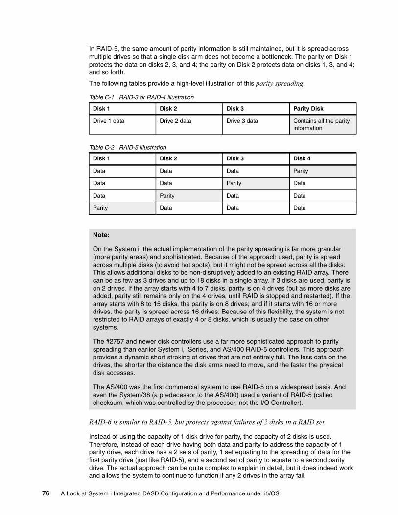
In RAID-5, the same amount of parity information is still maintained, but it is spread across multiple drives so that a single disk arm does not become a bottleneck. The parity on Disk 1 protects the data on disks 2, 3, and 4; the parity on Disk 2 protects data on disks 1, 3, and 4; and so forth.
The following tables provide a high-level illustration of this parity spreading.
Table C-1 RAID-3 or RAID-4 illustration
Table C-2 RAID-5 illustration
RAID-6 is similar to RAID-5, but protects against failures of 2 disks in a RAID set.
Instead of using the capacity of 1 disk drive for parity, the capacity of 2 disks is used. Therefore, instead of each drive having both data and parity to address the capacity of 1 parity drive, each drive has a 2 sets of parity, 1 set equating to the spreading of data for the first parity drive (just like RAID-5), and a second set of parity to equate to a second parity drive. The actual approach can be quite complex to explain in detail, but it does indeed work and allows the system to continue to function if any 2 drives in the array fail.
Disk 1 Disk 2 Disk 3 Parity Disk
Drive 1 data Drive 2 data Drive 3 data Contains all the parity information
Disk 1 Disk 2 Disk 3 Disk 4
Data Data Data Parity
Data Data Parity Data
Data Parity Data Data
Parity Data Data Data
Note:
On the System i, the actual implementation of the parity spreading is far more granular (more parity areas) and sophisticated. Because of the approach used, parity is spread across multiple disks (to avoid hot spots), but it might not be spread across all the disks. This allows additional disks to be non-disruptively added to an existing RAID array. There can be as few as 3 drives and up to 18 disks in a single array. If 3 disks are used, parity is on 2 drives. If the array starts with 4 to 7 disks, parity is on 4 drives (but as more disks are added, parity still remains only on the 4 drives, until RAID is stopped and restarted). If the array starts with 8 to 15 disks, the parity is on 8 drives; and if it starts with 16 or more drives, the parity is spread across 16 drives. Because of this flexibility, the system is not restricted to RAID arrays of exactly 4 or 8 disks, which is usually the case on other systems.
The #2757 and newer disk controllers use a far more sophisticated approach to parity spreading than earlier System i, iSeries, and AS/400 RAID-5 controllers. This approach provides a dynamic short stroking of drives that are not entirely full. The less data on the drives, the shorter the distance the disk arms need to move, and the faster the physical disk accesses.
The AS/400 was the first commercial system to use RAID-5 on a widespread basis. And even the System/38 (a predecessor to the AS/400) used a variant of RAID-5 (called checksum, which was controlled by the processor, not the I/O Controller).
76 A Look at System i Integrated DASD Configuration and Performance under i5/OS
Because of the additional protection RAID-6 provides, many customers implementing RAID-6 are doing so with a single larger array. With RAID-5, if a controller had 15 disks attached to it, the configuration usually consisted of 2 arrays—one with 7 disks, the other with 8, and a total capacity of 2 disks is used for parity. With RAID-6, a single 15-disk array would also have the equivalent of 2 disks used for parity, but the disk-level protection would be greater.
There is significant performance overhead involved in RAID-6 environments with heavy writes to disk application workload. A RAID-5 environment requires four physical disk accesses for each system issued write operation. A RAID-6 environment requires six physical disk accesses for the single system write operation. This is because two parity sets are maintained rather than just one. We discuss this more fully in the next section (“The RAID-5 and RAID-6 Write Penalty”). While it can protect against disk outages (which should be relatively rare with the SCSI drives used by the System i, but less so for the Serial ATA (SATA) drives where RAID-6 was initially implemented on other platforms), it does nothing to protect against disk controller or other component outages. If you need something greater than RAID-5 protection, mirroring (with double capacity disks) is usually preferable to RAID-6 (from both an availability and a performance perspective).
While RAID-6 does provide a greater level of protection than RAID-1, it is not strong as System i controller level mirroring (or higher). With RAID-1, within a single controller, if the first disk fails the system keeps running unless the mate of the failed disk also fails. If other disks in the RAID-1 set were to fail, the system continues to run. With RAID-6, after the first disk fails, any other disk in the same RAID-6 array can fail, and the system will continue to run. If a third disk were to fail, the system would cease to run; while with RAID-1, depending on which exact drives were failing, the system might continue to run with 3 or more failed drives. However, as stated before, System i usually uses controller level mirroring, not just RAID-1. If a disk controller were to fail in a RAID-1 or RAID-6 environment, the system will cease to function until the controller is replaced (and, for a System i, data in the write cache is restored). The popularity of RAID-6 on other platforms is due in part to their lack of controller level mirroring capabilities.
RAID-10 (aka RAID-1+0) uses the mirroring capability of RAID-1 with the data spreading provided by RAID-0.
The System i is considered RAID-10 compliant. While the function does not occur in the disk controller, i5/OS provides both mirroring and data spreading approaches that are far more comprehensive than those possible when using disk-controller-based RAID-10.
RAID-51 (also known as RAID-5+1) is a sometimes used term for a combination of RAID-5 plus a modification of RAID-1.
With this approach, the disks are protected through a RAID-5 approach, but there are essentially 2 disk controllers that are mirrored for each RAID-5 array. When properly implemented, there are also parallel paths to the two mirrored controllers. The customer gets the price savings of RAIDed disks, while the controllers are mirrored. These capabilities are supported by IBM Storage System products such as the DS6000™ and DS8000™ families that can be used with the System i.
Note: When using RAID-5, we recommended using disks of about one half the physical capacity as recommended in a mirrored environment. (See “Using double capacity disks in a mirrored environment” on page 91 for more information.) This can impact the savings available from RAID-5.
Appendix C. Understanding RAID-5, RAID-6, and associated performance considerations 77
The RAID-5 and RAID-6 Write PenaltyParity information is used to provide disk protection in RAID-5 and RAID-6 (also in RAID-3 and RAID-4, but because they are not used on System i and function similarly to RAID-5, we do not discuss them further). To maintain the parity, whenever data changes on any of the disks, the parity must be updated. For RAID-5, this requires:
� An extra read of the data on the drive being updated (to determine the current data on the drive that will be updated (changed)). This is needed to allow the calculation of any needed parity changes.
� A read of the “parity information” (to retrieve the current parity data that will need to be updated), and
� After some quick math to determine the new parity values, a write of the updated parity information about the drive containing the parity.
This nets out to 2 extra reads and 1 extra write that all occur behind the scenes and are not reported on the standard performance reports; plus the actual writing of the data—a total of 4 I/O operations.
With RAID-6, these activities also occur, but for 2 sets of parity drives. Therefore, in addition to the initial data read, there are 2 parity reads and 2 parity writes, and the actual write of the data. This means three extra reads, and two extra writes, plus the actual data update for a total of six I/O operations.
These extra activities have been termed the RAID Write Penalty. System i RAID-5 subsystems reduce/eliminate the write penalty via a true write cache (not just a write buffer) See Appendix B, “Understanding disk write cache” on page 69 for more information.
This cache disconnects the physical disk write from the reporting of the write complete back to the processor. The physical write (usually) occurs after System i has been told that the write has been performed. This hides the write penalty (actually write cache allows the write penalty to overlap with other disk and system activities so that it usually does not have a performance impact). The write cache also supports greater levels of disk activity in mirrored environments as well.
RAID-5 on System i and its predecessors: A brief historyRAID-5 and its predecessor, checksum, have been implemented on IBM products for over 25 years.
The basic RAID-5 parity structure was first implemented on the System/38 in the early 1980s in the form of checksum. Unlike today’s System i RAID-5 implementations, checksum was controlled by the main processor (not a separate outboard processor) and did not have a hot swap capability. An IPL (boot) was required after the disk was replaced, and during the IPL, the data was rebuilt (in dedicated mode). Today, RAID-5 and RAID-6 provide both hot swap capabilities and concurrent data rebuild while business operations continue.
RAID-5 DASD subsystems were introduced on the AS/400 in 1992 in the 9337 disk subsystem. This was one of the first widely installed RAID-5 implementations. Since that time, there have been continual enhancements. Two of the most noticeable of these were the advent of under the covers RAID-5 subsystems in 1994 with the AS/400 3xx models, and changes to RAID-striping approaches and enhanced performance levels with the announcement of the #2757 RAID controller in 2003.
RAID-5, RAID-6, and concurrent maintenance With RAID-5 and RAID-6, failing disks are replaced under concurrent maintenance through hot plugable capabilities while the system and the business continue to run. After the failed
78 A Look at System i Integrated DASD Configuration and Performance under i5/OS
drive is replaced (up to two failing drives with RAID-6), the data is reconstructed automatically, including the updates that occurred after the failure took place.
This reconstruction process is done in the background. Priority is given to user applications. The rebuild can take as little as one half hour or up to several hours, depending on system activity. The capacity and speed of the disks and disk controller, and in the case of RAID-6, if 1 or 2 disks are being replaced or rebuilt. It is important to note that no host CPU resources are used in the reconstruction process. It is all done outboard by the disk storage controller.
Calculating RAID-5 and RAID-6 capacityAll drives in each RAID-5 or RAID-6 array must have the same capacity. To calculate the usable capacity of each RAID-5 array, simply subtract 1 from the actual number of drives in the array and multiply the result by the individual drive capacity. For RAID-6, subtract 2 and multiply by the capacity. Using the latest System i controllers, the minimum number of drives in a single RAID-5 array is three and in a single RAID-6 array is four. The maximum is the lesser of 18 or the number of drives that can be placed in the disk enclosure (12 for a #5095/0595 or 15 for a #5094/5294).
High performance RAID controllers can support multiple RAID-5 or RAID-6 arrays, but most customers elect to use two RAID-5 arrays or one RAID-6 array per controller when used in #5094/5294/5095/0595 towers. Two RAID-5 arrays require the equivalent capacity of two extra disks for parity, which is the same as a single RAID-6 array. From an availability perspective, the single RAID-6 array provides better overall disk protection. From a performance perspective (in terms of the number of disk writes/second that can be performed), RAID-6 might provide fewer operations per second.
In a RAID-5 environment using a #5094/5294 tower, arrays of seven or eight disks provide a good balance between three RAID-arrays (of five or six drives each) per controller (for the best RAID performance and data protection) and a single array per controller (with up to 15 or 18 drives) which provides the greatest usable capacity, but has a slightly lower level of protection due to the number of disks in the array. A single large RAID-6 array provides the same capacity as a pair of RAID-5 arrays, but has potential performance implications. In an EXP24 environment using RAID-5, most customers will prefer 8 disks in each of 3 arrays (24 total on a single disk controller); or for RAID-6, 12 drives in each of 2 arrays.
RAID-5 and RAID-6 Performance in different situationsDuring normal operations, providing the disk activity is not exceeding the limits of the disk controller (going past the knee of the curve), IBM RAID-5 technology usually does not affect performance. You can expect the same interactive response times and the same batch throughput, with or without RAID-5.
The key disclaimer is “not exceeding the limits of the disk controller.” While the overhead of the write penalty (which we discussed earlier) is hidden by the write cache, the workload to do the extra reads and writes that RAID-5 or RAID-6 imposes behind the scenes does require resources. Therefore, as an example, a disk controller that might be capable of 900 to 1200 disk requests/second in a RAID-5 environment (6 to 12 k transactions, 50/50 read-to-write
Note: When mirroring is used, processing also continues to run, but the rebuild of the replaced disk is controlled by the System i processor, not the disk controller.
System i hardware also allows new drives to be hot added to a system (including their addition to a new or existing RAID-5 or 6 array). Other servers typically can only add drives hot to their system if the drives are attached via an external SAN attachment. the System i can add any type of drives hot.
Appendix C. Understanding RAID-5, RAID-6, and associated performance considerations 79
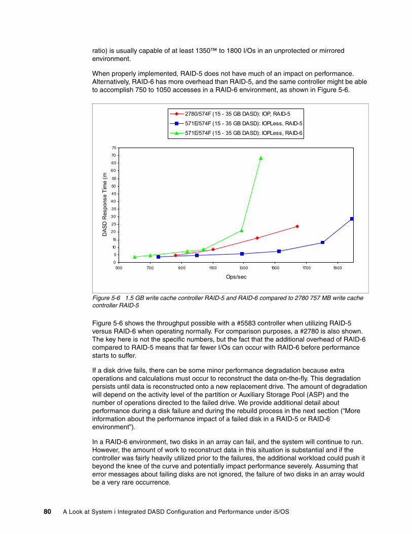
ratio) is usually capable of at least 1350™ to 1800 I/Os in an unprotected or mirrored environment.
When properly implemented, RAID-5 does not have much of an impact on performance. Alternatively, RAID-6 has more overhead than RAID-5, and the same controller might be able to accomplish 750 to 1050 accesses in a RAID-6 environment, as shown in Figure 5-6.
Figure 5-6 1.5 GB write cache controller RAID-5 and RAID-6 compared to 2780 757 MB write cache controller RAID-5
Figure 5-6 shows the throughput possible with a #5583 controller when utilizing RAID-5 versus RAID-6 when operating normally. For comparison purposes, a #2780 is also shown. The key here is not the specific numbers, but the fact that the additional overhead of RAID-6 compared to RAID-5 means that far fewer I/Os can occur with RAID-6 before performance starts to suffer.
If a disk drive fails, there can be some minor performance degradation because extra operations and calculations must occur to reconstruct the data on-the-fly. This degradation persists until data is reconstructed onto a new replacement drive. The amount of degradation will depend on the activity level of the partition or Auxiliary Storage Pool (ASP) and the number of operations directed to the failed drive. We provide additional detail about performance during a disk failure and during the rebuild process in the next section (“More information about the performance impact of a failed disk in a RAID-5 or RAID-6 environment”).
In a RAID-6 environment, two disks in an array can fail, and the system will continue to run. However, the amount of work to reconstruct data in this situation is substantial and if the controller was fairly heavily utilized prior to the failures, the additional workload could push it beyond the knee of the curve and potentially impact performance severely. Assuming that error messages about failing disks are not ignored, the failure of two disks in an array would be a very rare occurrence.
0
5
10
15
20
25
30
35
40
45
50
55
60
65
70
75
500 700 900 1100 1300 1500 1700 1900
Ops/sec
DAS
D R
espo
nse
Tim
e (m
2780/574F (15 - 35 GB DASD): IOP, RAID-5
571E/574F (15 - 35 GB DASD): IOPLess, RAID-5
571E/574F (15 - 35 GB DASD): IOPLess, RAID-6
80 A Look at System i Integrated DASD Configuration and Performance under i5/OS
More information about the performance impact of a failed disk in a RAID-5 or RAID-6 environment
What is the performance impact in RAID-5 or RAID-6 when a drive fails? How long does it take to rebuild a drive? We address the answers to these questions for RAID-5 further in this section. The information applies similarly to a failed disk in a RAID-6 environment. Recognize, however, that the number of disk I/Os per second that can occur in a RAID-6 environment is greater than that in a RAID-5 environment because the overhead of maintaining two sets of parity drives is much higher.
These seemingly straightforward questions are deceptively difficult to answer without knowing additional specifics about the RAID-5 or RAID-6 arrays and the overall system. You need to understand the following questions:
� Are you concerned about the performance impact on the specific disk array or overall system responsiveness and throughput?
� Are you looking at the impact on the other drives in the same RAID-5 or RAID-6 set?
� How many disks are in the RAID-5 or RAID-6 set?
� What is the capacity of each drive?
� How many RAID-5 or RAID-6 arrays are on the system?
� How busy were the disk drives before the failure?
The simple answer is that if a system has multiple RAID-5 or RAID-6 arrays and a single drive fails in a single array, there will be an impact on the drives in the specific RAID-5 or RAID-6 array, but there might be no discernible impact to overall system performance.
Alternatively, if there is only one 4-drive RAID-5 or RAID-6 array for the entire system and the drives are very busy before the failure, the impact might be considerable. An example will help with our discussion.
Assume a single drive has failed. Let us examine how the failure impacts different types of activities:
– When performing a read operation, the obvious question becomes: Is the requested data on the drive that failed? If the data is on a drive that is still operating, there is no impact. However, if the data is on the failed drive, all of the other drives in the array must be accessed to allow reconstruction of the missing data.
– For writes, if both the drive containing the data and the drive containing the parity are operational, there is no impact. If the data or parity drive is experiencing the failure, data is only written to the disk that is still operating (performance can actually improve, but data is not protected).
In RAID-5 arrays with only a few drives (four or five), the probability of the requested data being on the “failed” drive is greater, but the number of reads that must occur to reconstruct missing data is less. The opposite is true for larger arrays (eight to 18 drives).
So, what is the performance impact? It depends! How busy are the drives? Using a high performance disk controller with 15 k rpm disk drives, each disk is usually capable of 60 to 80 accesses/second with good performance (potentially more, depending on which high speed controller is being used).
Assume each drive is only doing 40 accesses per second when a failure occurs. In this case, the additional workload generated to reconstruct data on the fly is probably still less than the number of accesses the drive can perform each second. Therefore, the performance change might not be observable. Alternatively, if the 15 k rpm drives were already doing 65+ accesses each second, the impact might be considerable, but the system would at least continue to operate.
Appendix C. Understanding RAID-5, RAID-6, and associated performance considerations 81
When a drive fails, it only affects the performance of the RAID-5 or RAID-6 array that contains that drive. All other RAID arrays continue to operate at normal speed. Depending on the number of arrays on the system, there might or might not be a recognizable impact. Because most customers are not pushing their drives during normal operations, the impact of a drive failure is usually minimal, especially if the system has multiple arrays.
RAID-5 or RAID-6 performance during disk rebuild operationsPreviously, we discussed the impact on performance while a drive has failed, but is still physically in the system. Now, let us assume the drive has just been replaced. While operations continue, the data on the drive must be reconstructed.
The time needed for the data rebuild depends on the amount of activity in the RAID array, the number of drives in the array, the speed disk controller, and the capacity of the drives. It can take from less than an hour to several hours to rebuild the drive. The system’s first priority is to service business requests from the applications. Additional available accesses are used to rebuild the drive.
When each disk sector is rebuilt, corresponding sectors are read from all the other drives in the array, calculations are performed, and the sector is written to the newly replaced drive. Multiple sectors are processed concurrently. As soon as a sector has been rebuilt, its data can be accessed directly. An example might help.
Assume a drive has been replaced and that 20% of the data has been reconstructed onto the new drive. A disk read request is issued to the drive being reconstructed. If the request is for data from the first 20% of the drive (the portion that has been rebuilt), the data is accessed directly. If data that has not yet been reconstructed is requested (beyond the first 20% in our example), the data must be built by gathering information from all of the other drives in the array.
A similar situation exists for writes. If the data is on the portion of the disk that has been recovered, it will be written to both this drive and the parity drive. If the data has not yet been placed on the drive, only the parity data is written. If, however, the data that needed to be written was really parity data, and the rebuild process had not yet reached that portion of the disk, the system would simply not write the parity data, it will be recreated when the process gets to that section of the disk.
As more and more of the data is reconstructed, the build on the fly requests become fewer and fewer. Less work is placed on the disk subsystem, and the rebuild process has more accesses available. Therefore, as more of the drive is rebuilt, the rebuild process goes faster. One should also note that all of this activity is being performed by the disk controller, not the main System i processor.
Recovery from a RAID controller failure: The importance of auxiliary write cache
While RAID-5 or RAID-6 protects against disk failures, it does not protect against disk controller failures. If a controller fails in a RAID environment, the system (or at least that LPAR or Independent ASP) will stop running until the controller is replaced. Thus, if there is no Auxiliary Write Cache, a system reload might be required.
When a controller failure occurs in the RAID environment, there are two possible situations that occur during or after the controller replacement process. Which situation actually occurs usually depends on whether the controller is using an auxiliary write cache.
Note: Time statements are for 15 k rpm disk. The same approaches apply to 10 k rpm drives, but rebuild times are longer.
82 A Look at System i Integrated DASD Configuration and Performance under i5/OS
Prior to replacing the disk controller, the service person attempts to recover data from the disk controller’s write cache. This is important because the cache contains data that has been written to the controller, but not yet written to disk. In some cases, the cache is removable, but it could be the removable cache that is failing. In other cases, the service representative might or might not be able to use other techniques to recover this data. The disk controller is then replaced.
� If the service representative was able to retain or recover the information from the cache, or if there was an auxiliary write cache, the cached data is restored to the new controller and is then written to disk. The system can then be restarted.
� If the service representative was unable to retain the information from the cache or if there was no auxiliary write cache, the data on the disks will not be up to date. A large number of different objects are likely to be affected; so many, that a reload is usually required. If the system has multiple LPARs, or the problem occurred in an Independent Auxiliary Storage Pool (IASP), only that LPAR or IASP will be affected. If the customer is not using LPARs or IASPs, an entire system reload could be required.
The currency of the data being restored during the reload will of course depend on when the last backups were performed, and whether or not journaling was running and the journal receivers were available. This approach might be acceptable if customers are running resilient systems, but for customers not running high availability software, a minimum of RAID-5 with Auxiliary cache is usually recommended.
Some conclusions about RAID-5 and RAID-6 implementations on the System i
RAID-5 and RAID-6 support on System i provide protection for failures at the disk, but not the controller level. With RAID-5 a single disk can fail (in each RAID array) and the system will continue to run. With RAID-6, two disks can fail in each array, and the system remains running. When a failing disk(s) is replaced, the drive is automatically rebuilt behind the scenes.
However, RAID-5 and 6 only protects against disk, not disk controller failures. If the controller were to fail, the system (or at least the LPAR or independent ASP) will cease to operate until the controller is replaced. When the controller is replaced, data still in the write cache of the controller card might or might not be recoverable. If it is not recoverable, a second copy of the cached data from the auxiliary write cache feature (which we strongly recommend for use in RAID-5 and 6 environments but is not available for smaller or older RAID-capable controllers or might not have been added to auxiliary cache capable controllers) is used to restore the write cache so that data that had not yet been written to disk can be destaged. If the auxiliary write cache was not available, a system (or LPAR or ASP) reload could be required.
However, in a system that is mirrored to a minimum of the disk controller level, a disk controller failure does not cause downtime. If the controller fails, the controller running the other side of the mirror continues to operate. After the failing controller is replaced, the mirrored disks are re-synchronized. Additionally, in a mirrored environment, it is usually viable to use disks of larger physical capacity than in a RAID-5 or RAID-6 environment. We discuss these concepts in Appendix D, “Mirroring” on page 85.
Appendix C. Understanding RAID-5, RAID-6, and associated performance considerations 83

84 A Look at System i Integrated DASD Configuration and Performance under i5/OS
Appendix D. Mirroring
While it should be obvious that mirroring (at a minimum of the disk controller level) provides higher levels of availability than other levels of RAID, what might be less obvious are considerations such as:
� The system continues to run during a disk controller outage (unlike RAID-5 or RAID-6 where the system, or LPAR or Independent ASP, is down until the disk controller is replaced).
� The auxiliary write cache protection, so important in a RAID-5 or RAID-6 environment, is not usually considered necessary in a mirrored environment, except when mirroring only the disks and not the controllers.
� The same number (or sometimes fewer) double capacity disk drives can provide the same level of performance and greater capacity than the same number of disks in a RAID-5 or RAID-6 environment.
� A disk controller can perform far more disk accesses each second in a mirrored environment than in a RAID-5 or RAID-6 environment because while the reported number of disk writes issued by programs in a mirrored environment increases, the actual I/O activity at the disk level decreases.
We discuss each of these considerations, as well as several others, in this appendix.
D
© Copyright IBM Corp. 2008. All rights reserved. 85
Mirroring overview
Between the disk level protection offered by RAID-5 and 6 and the cross-system protection offered by resilient clustering solutions is the mirroring approach. i5/OS mirroring not only protects the data on disk drives, but as usually implemented, provides protection against disk controller, disk tower, and even High Speed Link (HSL) connection failures. Depending on the implementation, failures in any of these areas can occur and the system would continue to run.
Another advantage of mirroring is the fact that if more than one disk drive fails in the same RAID-5 disk array (more than two for RAID-6), there is no disk protection, but with mirroring the only disk of concern would be the mirrored mate. While this can still happen, with the reliability of the disks used in the System i (SCSI, not ATA or SATA type of drives) such an outage would be very rare (assuming the system was not left in a disk failed state for an extended period). Protection against failures in other components protected by mirroring but not by RAID-5 or 6 are probably more important.
While you might be concerned about additional costs for duplicate devices in a mirrored environment, the expense might not be as high as expected. With mirroring, it is often possible to use the same number (or sometimes less) double capacity disks as in a RAID-5 or RAID-6 environment. Therefore, the same number of disk controllers and enclosures can be used. The primary additional expense becomes the larger capacity disk drives. We discuss this more fully in “Using double capacity disks in a mirrored environment” on page 91.
Disk activity and performance during normal mirrored operations
There are differences in the level of disk activity and the workload on the disk controller that occur in a mirrored environment compared to a RAID-5 or RAID-6 environment. For the same workload, while the system reported number of disk accesses shows that a mirrored environment is generating more disk activity than a RAID-5 or RAID-6 environment, the opposite is actually the case.
The reason for this is that the system only reports what it can see (unless you get into very detailed reporting). When a write occurs to the disk subsystem, it is reported. For RAID-5 or RAID-6, this is one write at the system level, but at the disk level, there are additional reads and writes occurring to keep the parity updated. In a mirrored environment, there are writes to both sides of the mirror. Both are reported, but each system level write results in only one disk level write (which might be eliminated or combined due to the caching capabilities of the disk controller). The net is, a mirrored environment places less actual workload on the disks and the disk controllers.
Note: We have seen situations where a RAID-5 protected disk failed, and the system sent messages to the operator. However, because of the RAID-5 protection, the system continued to function, and the messages were ignored. Then, weeks or months later, a second disk in the array failed, and the system went down. It is very important that repair actions are taken (not delayed) when these messages occur.
86 A Look at System i Integrated DASD Configuration and Performance under i5/OS
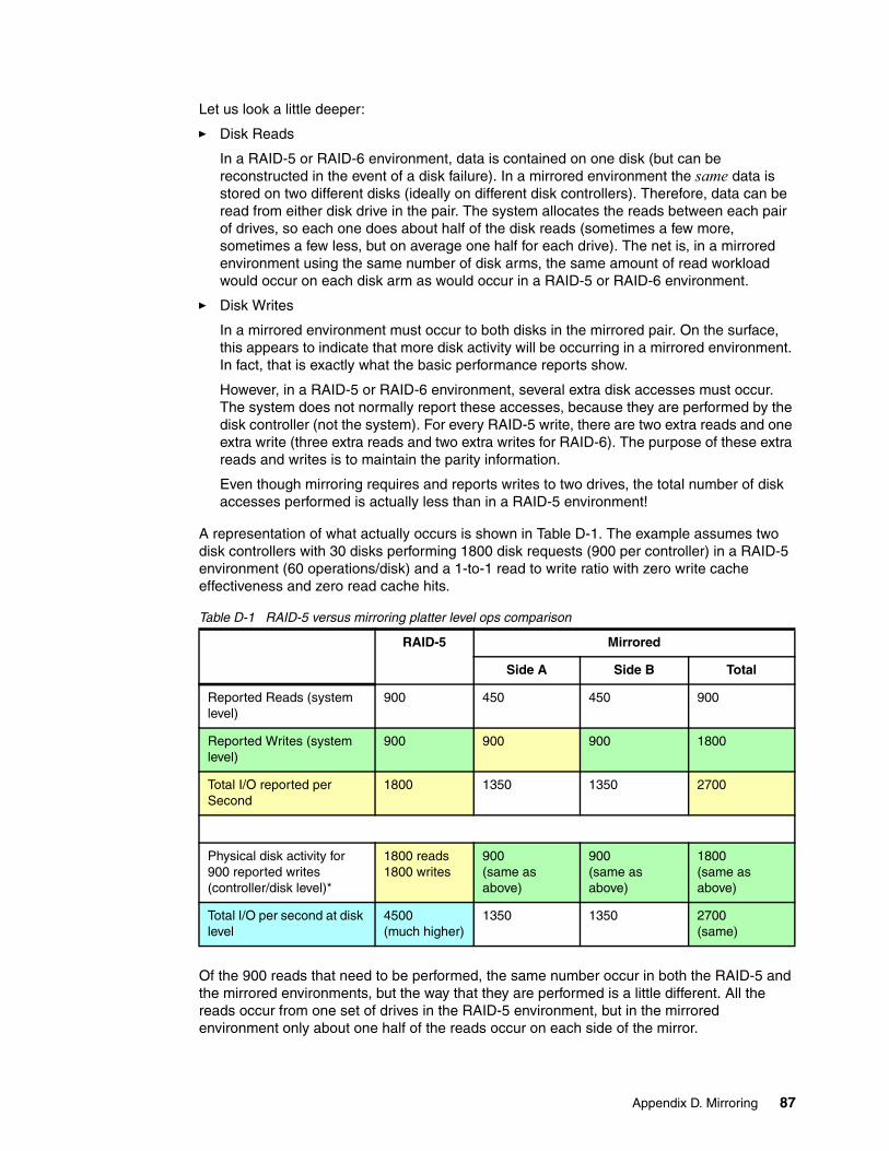
Let us look a little deeper:
� Disk Reads
In a RAID-5 or RAID-6 environment, data is contained on one disk (but can be reconstructed in the event of a disk failure). In a mirrored environment the same data is stored on two different disks (ideally on different disk controllers). Therefore, data can be read from either disk drive in the pair. The system allocates the reads between each pair of drives, so each one does about half of the disk reads (sometimes a few more, sometimes a few less, but on average one half for each drive). The net is, in a mirrored environment using the same number of disk arms, the same amount of read workload would occur on each disk arm as would occur in a RAID-5 or RAID-6 environment.
� Disk Writes
In a mirrored environment must occur to both disks in the mirrored pair. On the surface, this appears to indicate that more disk activity will be occurring in a mirrored environment. In fact, that is exactly what the basic performance reports show.
However, in a RAID-5 or RAID-6 environment, several extra disk accesses must occur. The system does not normally report these accesses, because they are performed by the disk controller (not the system). For every RAID-5 write, there are two extra reads and one extra write (three extra reads and two extra writes for RAID-6). The purpose of these extra reads and writes is to maintain the parity information.
Even though mirroring requires and reports writes to two drives, the total number of disk accesses performed is actually less than in a RAID-5 environment!
A representation of what actually occurs is shown in Table D-1. The example assumes two disk controllers with 30 disks performing 1800 disk requests (900 per controller) in a RAID-5 environment (60 operations/disk) and a 1-to-1 read to write ratio with zero write cache effectiveness and zero read cache hits.
Table D-1 RAID-5 versus mirroring platter level ops comparison
Of the 900 reads that need to be performed, the same number occur in both the RAID-5 and the mirrored environments, but the way that they are performed is a little different. All the reads occur from one set of drives in the RAID-5 environment, but in the mirrored environment only about one half of the reads occur on each side of the mirror.
RAID-5 Mirrored
Side A Side B Total
Reported Reads (system level)
900 450 450 900
Reported Writes (system level)
900 900 900 1800
Total I/O reported per Second
1800 1350 1350 2700
Physical disk activity for 900 reported writes (controller/disk level)*
1800 reads1800 writes
900(same as above)
900(same as above)
1800(same as above)
Total I/O per second at disk level
4500(much higher)
1350 1350 2700(same)
Appendix D. Mirroring 87
From a write perspective, in a mirrored environment, every write from the program generates two reported writes to disk—one for each side of the mirror (therefore 1800 reported writes are shown for mirroring in the above table). These writes are then cached in the controller and many of them are combined or eliminated before a physical write ever occurs to disk.
Compare this to RAID-5 where each program generated write results in a single reported write to the controller. This single write is what is reported to the performance tools (versus the two writes in the mirrored environment). However, in a RAID-5 environment, after the controller receives the write, it must generate two extra reads (one for the original data that is updated to calculate the net difference in the parity and one for the existing parity data to allow the calculation of the net change to make to the parity data), plus one extra write (for the parity data), plus of course the write of the actual data being updated.
Therefore, the workload for each logical disk write in a RAID-5 environment is quite intensive on the disks and controllers (two physical reads and two physical writes) versus the two writes (both of which are reported to the performance tools) in a mirrored environment.
From a performance perspective the response times with mirroring are usually identical to those in a RAID-5 environment. However, because the amount of work required to do a mirrored write is much less, the actual I/O workload sent to the controller level can be much higher. As shown in Table D-1, if there is a 1-to-1 read to write ratio, the number of disk I/Os sent to the controller will increase 50%, but the controller is actually performing far fewer disk operations than it would be doing in a RAID-5 environment. Therefore, to be conservative, if a disk controller was capable of 900 to 1200 operations/second in a RAID-5 environment, it would be capable of at least 1325 to 1800 operations in a mirrored environment and probably more.
The reason for the conservatism is due to the write cache. A disk write operation sent to the controller does not necessarily result in a physical disk write. The cache can combine and eliminate writes. If a high percentage of the logical writes in a RAID-5 environment were eliminated by the cache, the affect on physical writes to the disk might not be as large as might have been anticipated. The cache also helps with handling the additional writes imposed by a mirrored environment. The net is, as stated above, the ability of a disk controller to handle a 50% increase in disk accesses is usually a conservative number to apply when moving from a RAID-5 environment to a mirrored environment. If moving from a RAID-6 to a mirrored environment, a 67% increase is usually possible.
You can use the IBM Systems Workload Estimator to estimate the quantity of different disk units needed based on DASD protection. More information about this tool is available at:
http://www-304.ibm.com/jct01004c/systems/support/tools/estimator/index.html
Mirroring performance during disk outage operations
What is the performance impact when a mirrored drive (or some other mirrored storage component) fails? How long does it take to rebuild a drive?
These are deceptively difficult questions. Before answering these questions, other questions must be asked, such as:
� Are we concerned about the performance the other drive in the mirrored pair or overall system responsiveness and throughput?
� How many drives are on the system?
� How busy were the disk drives before the failure?
88 A Look at System i Integrated DASD Configuration and Performance under i5/OS
The simple answer is that if a system is mirrored and a single drive fails, there might or might not be an impact on the corresponding mirrored drive. It depends on how busy it was prior to the outage. The number of writes on the still operational disk remains the same, but the number of reads doubles (because prior to the outage, reads were allocated between the two drives). Because disk controllers usually bottleneck before the physical disk drives, unless the controller is close to being overloaded, there might be no discernible impact. Furthermore, even if there is an impact to a single disk drive, there might be no discernible impact to overall system performance. Some examples might help:
1. If there are only two or four disks for the entire system, and the drives are very busy before the failure, the impact might be considerable.
If each disk was performing 50 disk operations per second, allocated 50% to reads and 50% to writes, it would mean that after the failure the drive would need to perform 75 disk operations/second.
This would occur, because the 25 read requests that were previously being performed by the drive that is now experiencing an outage constituted about one half of the total read requests (the other half was going to the other drive in the mirrored pair). With the mirrored drive unavailable, all of the reads would need to occur from the remaining drive. Because writes occur on both drives in the mirror, the failure of the other drive would have no impact on the write workload.
If the disk in question was a 10 k rpm disk, the 75 requests/second would probably cause a bottleneck on that drive. However, if it was a 15 k rpm disk, the 75 requests would probably not be a problem.
2. If there were 50 disks on the system, and an outage occurred, 48 drives would run at the normal speed, one drive would be down and one drive would be doing additional work. Even if that disk started to bottleneck (usually it would no), if there were no bottlenecks in the disk controllers, over 97% of the disk activity would be performing at normal speeds.
Mirroring performance during disk drive rebuild operations
Thus far, we have discussed the impact on performance while a drive has failed, but is still physically in the system. Now, let us assume the drive has just been replaced. While operations continue, the data on the drive must be reconstructed.
The time needed for the data rebuild depends on the amount of activity on the other disk in the mirrored pair, the disk controllers, and the capacity of the drives. It can take from less than an hour to several hours to rebuild the drive. The first priority is to service business requests from the system. Additional available accesses are used to rebuild the drive.
If both disks are on the same disk controller, there could be an impact on the controller (depending on its speed and the activity on the system). If the disks are on different controllers, both controllers will be affected, but the impact on each controller will be less.
As each set of sectors is read from the disk still operating and written to the newly replaced disk, the workload on the still active disk is reduced, and the workload on the disk being rebuilt increases. This is because the disk being rebuilt is available to perform disk accesses to the already rebuilt section of the data, and must perform additional writes when data is updated in the mirrored pair.
Note: In this scenario, all the disks were probably on a single controller. Therefore, the workload on that controller actually decreases.
Appendix D. Mirroring 89
An example might help.
Assume a drive has been replaced and that 20% of the data has been reconstructed onto the new drive. A disk read request is issued. If the request is for data from the first 20% of the drive (the portion that has been rebuilt), the data can be read from either of the two drives in the mirrored pair. If data that has not yet been copied onto the replacement drive is requested, (beyond the first 20% in our example), it must still be accessed from the other drive in the mirror.
Likewise, if data is already on the replacement drive and a write or update occurs, it must occur on both sides of the mirror. If the data has not yet been copied onto the new disk, it cannot be updated.
As more and more of the data is rebuilt, the read activity is increasingly spread between the mirrored pair, and the write activity on the drive being rebuilt increases. Therefore, as more of the drive is rebuilt, more activity will occur on the new drive and less on the other drive in the mirrored pair.
There are two other items that differ slightly from the RAID-5 or RAID-6 rebuild scenario:
1. If the disks in the mirrored pair are not overly busy, the process can be relatively rapid. Both drives can be on the same relative track at the same time and the data is simply transferred sequentially.
2. Unlike RAID-5 or 6, the main System i processor must be involved with this rebuild activity.
Recovery from a controller failure with mirrored disk controllers
Mirroring at the controller level or greater protects against both disk drive and controller failures. If a disk controller fails under RAID-5 or 6 or a disk-only level of mirroring, the system (or at least that LPAR or Independent ASP) stops functioning. In a mirrored controller environment, operations continue.
The approach used when replacing a disk controller on a system that is still running is different from that used in the case of an unmirrored controller (when the system has stopped).
� In the unmirrored controller situation, the auxiliary write cache is very important. See Appendix C, “Understanding RAID-5, RAID-6, and associated performance considerations” on page 73 for more information.
� In the mirrored controller situation, the controller that is still active continues to update the disks under its control. Therefore the disks attached to the failed controller are getting further and further out of synchronization, and the data in an auxiliary write cache becomes more and more obsolete and, therefore, useless.
In the mirrored controller situation, after the controller is replaced, it is varied on. At that point, the system realizes that the data on the attached disks is obsolete and starts to rebuild them using the data from the mirrored mates. These drives had continued to function and receive updates during the outage of the other controller (see previous section on disk performance during disk drive rebuild operations).
The only difference from an individual disk drive rebuild, is the fact that all the drives under the controller need to be copied/refreshed with the current data. This takes considerably longer than copying or refreshing a single disk, and the disk controller is much more heavily utilized during the rebuild process. The actual time required will depend on the capacity of the disks, the speed of the controller, and the level of concurrent business-oriented processing that the disks must continue to perform while the refreshes take place.
90 A Look at System i Integrated DASD Configuration and Performance under i5/OS
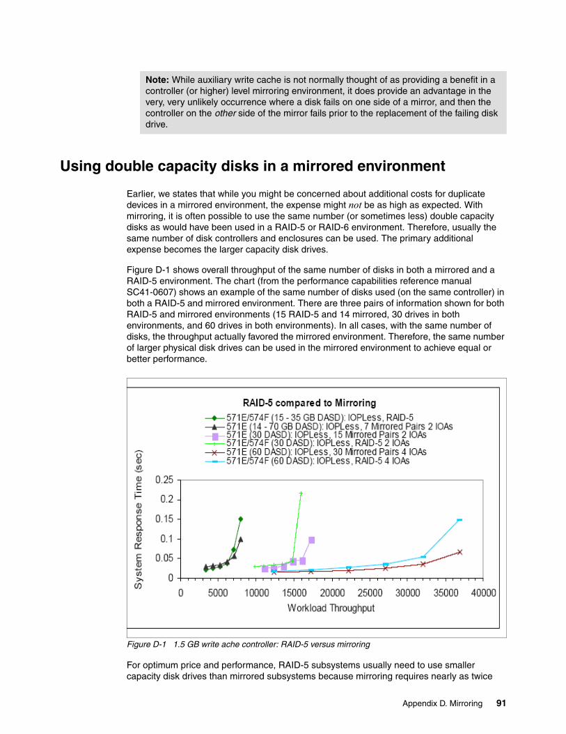
Using double capacity disks in a mirrored environment
Earlier, we states that while you might be concerned about additional costs for duplicate devices in a mirrored environment, the expense might not be as high as expected. With mirroring, it is often possible to use the same number (or sometimes less) double capacity disks as would have been used in a RAID-5 or RAID-6 environment. Therefore, usually the same number of disk controllers and enclosures can be used. The primary additional expense becomes the larger capacity disk drives.
Figure D-1 shows overall throughput of the same number of disks in both a mirrored and a RAID-5 environment. The chart (from the performance capabilities reference manual SC41-0607) shows an example of the same number of disks used (on the same controller) in both a RAID-5 and mirrored environment. There are three pairs of information shown for both RAID-5 and mirrored environments (15 RAID-5 and 14 mirrored, 30 drives in both environments, and 60 drives in both environments). In all cases, with the same number of disks, the throughput actually favored the mirrored environment. Therefore, the same number of larger physical disk drives can be used in the mirrored environment to achieve equal or better performance.
Figure D-1 1.5 GB write ache controller: RAID-5 versus mirroring
For optimum price and performance, RAID-5 subsystems usually need to use smaller capacity disk drives than mirrored subsystems because mirroring requires nearly as twice
Note: While auxiliary write cache is not normally thought of as providing a benefit in a controller (or higher) level mirroring environment, it does provide an advantage in the very, very unlikely occurrence where a disk fails on one side of a mirror, and then the controller on the other side of the mirror fails prior to the replacement of the failing disk drive.
Appendix D. Mirroring 91
much raw disk capacity as a RAID-5 subsystem to provide the same amount of usable storage. Therefore, a mirrored system needs either almost twice as many disk arms (of the same capacity), or it can use drives with twice the capacity and the same or fewer number of disk arms.
The key to performance is having sufficient disk arms (and controller power) to meet the needs of the workload. The minimum number of arms needed is the critical item. Additional arms will usually not improve performance.
The following example provides some additional detail and shows why it is sometimes possible to use fewer disk arms in a mirrored environment than in a RAID-5 environment.
The main portion of this paper discusses the importance of having sufficient disk arms to provide adequate storage capacity and to meet the needed performance objectives (which can be thought of as enough I/Os each second). To meet both objectives, a balance is usually struck between the number of disks needed to meet the performance objective, and the size of the disk drives used so that the needed capacity is met. An example can help show these requirements.
Assume a customer requires a usable or protected disk capacity of 900 GB and needs to perform 1200 disk requests/second. Also assume that each disk drive is able to perform 60 disk accesses/second with good performance. 15 k rpm disks will be used.
In this example, to meet the performance objective, the system needs 20 disk arms (1200 operations/second and 60 operations/second/drive). However, using 35 GB disk drives in a RAID-5 environment, the 20 disk arms needed to meet the performance objective would only provide 630 GB of usable capacity (18 drives of capacity, plus two drives for parity capacity, assuming the recommended two RAID-5 arrays). To meet the capacity objective, they need 30 disk arms (26 disks of capacity (910 GB) plus four drives for parity capacity, assuming four RAID-5 arrays).
Alternative, in a mirroring environment using 70 GB disk drives, 20 disk arms would provide 700 GB of protected storage (20/2 = 10 mirrored pairs of 70 GB drives), and 26 mirrored drives would provide 910 GB of storage. Both the capacity and the performance requirements are met with fewer double capacity disk drives (in this case).
In this example, the factor driving the minimum number of disk arms was capacity. If the factor driving the minimum number of disk drives had been performance, the same number of double capacity disks can always be used in a mirroring environment (compared to base capacity disks in a RAID-5 environment).
However, due to mirroring placing less stress on the disk controllers, it is often possible to reduce the number of disks in a mirrored environment to match the number of arms that provide the same RAID-5 usable capacity (that is, subtract the number of disks required for storage of parity information in the RAID-5 environment).
Some conclusions about mirroring implementations on the System i
RAID-5 and 6 are very viable. However, other failures, beyond just disk drive failures, can result in a system outage. Mirroring, at a minimum of the disk controller level, provides
Note: This assumes that proper sizing was done for the RAID-5 environment to ensure that there are sufficient disk arms to meet the needed capacity and performance objectives.
92 A Look at System i Integrated DASD Configuration and Performance under i5/OS
additional benefits that go beyond protecting the disks themselves. Mirror protection allows the system to continue to run normal operations when various hardware components of the DASD subsystem fail, assuming the disks are protected at the appropriate level of mirroring. If data must be available at the highest level, evaluation of the solutions provided by High Availability Business Partners (HABPs) should be done.
The clustering products from companies such as Lakeview Technologies, Vision Solutions, Data Mirror, iTera, Maximum Availability and Traders provide a high level of data availability than what RAID-5, RAID-6, or disk mirroring can provide. These solutions utilize cross-system clustering and data replication capabilities that can help address both planned and unplanned downtime. Because the systems themselves are viewed as mirrored, most customers using these software products feel RAID-5 protection is a cost-efficient way to protect the drives themselves.
Other availability approaches that are beyond the scope of this paper include Independent ASPs and Cross Site Mirroring (XSM).
Appendix D. Mirroring 93

94 A Look at System i Integrated DASD Configuration and Performance under i5/OS
Appendix E. Additional examples of situations using mixed capacity disk drives
In 2.4.1, “Overall disk sizing considerations” on page 15, we discussed various approaches to use when adding disk drives to the same LPAR or ASP, especially if the drives do not have the same capacity.
This appendix contains additional examples about the potential impacts of mixing different disk drive capacities.
E
© Copyright IBM Corp. 2008. All rights reserved. 95
Example 1
Example 1 is a relatively simple example.
A customer on a 570 currently has about 2 TB of data on 66 35 GB disks. They need an additional 1 TB of data and would like to use nine 140 GB drives on a disk controller of similar speed and capacity. Because the number of disk arms will increase, they do not think they will have a problem. Will they?
We do not have enough information to know, but the odds are that they will have a problem. We need to know the current level of disk activity and whether there will be increased activity in the future. With an increase in capacity, it is probable that the number of requests will also increase.
The customer currently has 66 disk arms to do all the disk accesses. When they go from 2 TB to 3 TB and rebalance, about one third of all the disk requests will now occur on only 9 disk drives (actually a little more, because they will have 1.128 TB of usable capacity on the nine arms).
The nine arms have a potential to be very busy. How busy they are depends on the current activity level. Performance information is needed for a high activity time period. Some potential outcomes are:
– If they are currently doing 20 ops/second/drive, the system is doing 1320 ops total and in the new environment the nine drives will end up doing 1320/3 = 440 or about 440/9 = 49 ops/second, which will probably not be a problem.
– If they are currently doing 30 ops/second/drive, the system is doing 1980 ops total and in the new environment the nine drives will end up doing 1980/3 = 660 or about 660/9 = 73 ops/second. Probably causing no performance impact, but if the 30 was an average, they could run into problems at peak times.
Again, probably not an issue with only nine drives on a #5580 controller, but if they later added more drives to the #5580 (increasing the ops/second for the controller), the controller could experience difficulties in keeping up with the ops rate.
– If they are currently doing 40 ops/second/drive, the system is doing 2640 ops total and in the new environment the nine drives will end up doing 2640/3 = 880 or about 880/9 = 98 ops/second—a potential problem. With 12 drives attached to a #5580, we usually recommend to size to 75 disk ops/second/drive to allow peaks of 100 ops/drive. With only nine drives on the 5580, we might be able to go a little higher, but they could be on the edge of the knee of the curve.
– Anything more than 40 ops/second/drive in the current environment will cause a problem.
Example 2a
This scenario is straightforward with some real-world considerations are added.
A customer has 10 35 GB 15 k rpm disks and is performing 75 disk operations/second/drive (750 total for the controller). The normal guideline for the disk controller they are using is to run between 900 and 1200 operations per second (ops).
With 15 disks, this would mean 60 disk operations/second per drive, but because they are only using 10 of the 15 disks that the controller supports, they are able to run with good performance. The 15k rpm drives will not bottleneck until something over 100 disk ops are reached. The disk enclosure and controller can support 15 disks. They need to double
96 A Look at System i Integrated DASD Configuration and Performance under i5/OS
their disk capacity by adding five 70 GB disks. Ignoring RAID-5 or RAID-6 parity considerations, would this be a problem?
As they double the capacity, they will not initially increase the workload on the controller. It will just be re-spread between the disks. In the past, the 700 disk operations were being performed by 10 drives. Now, half the disk capacity will be on 10 drives and the other half will be on 5 drives. The number of disk requests will be allocated in the same way. Therefore 10 of the disks will do 375 disk requests (37.5 per drive), and the other 375 requests will be done on the 5 new disks which is 75 disk operations per drive. The net is that a problem does not yet exist.
Example 2b
We expand the scenario from Example 2a by using the new capacity to add new workload.
In reality, the reason that they needed to double their disk capacity was that they have just acquired another company, and the workload on the system will be immediately increasing by 50% (and then growing further into the future). So instead of doing 750 disk requests/second, they will be doing 1125 requests. Now is it a problem? Why?
The answer is yes, it is a problem. First, from a disk controller perspective. While 1125 ops is less than the 1200 ops the controller can handle, it is getting too close to the knee of the controller’s curve. The 900 to 1200 guideline for the controller is to size to 900 to allow peaks of 1200. If we size to 1125, the first peak that occurs is likely to cause performance problems.
Second, from a disk perspective. The 10 35 GB disks will now perform 1125/2 = 562 disk operations/second, or 56 per drive. The five 70 GB drives will perform 562/5 = 112 disk ops. This is greater than 100 so could cause a bottleneck at the disk level, especially when a peak is encountered.
Neither of these answers deals with the increasing workload as the customer moves into the future. While they might be able to get by today, they are right on the knee of the curve for both the disks and the controller. It will not take much additional workload to push them into major performance problems.
We provide additional information in 2.4.1, “Overall disk sizing considerations” on page 15.
Appendix E. Additional examples of situations using mixed capacity disk drives 97

98 A Look at System i Integrated DASD Configuration and Performance under i5/OS
Appendix F. References to articles on future disk technologies and replacements
For many years (since the days prior to the System/38), it was thought that magnetic disk technologies would not continue to develop as rapidly as the demands for storage. This is the reason that we often refer to disks as Direct Access Storage Devices (DASD). The architecture of the System i and its predecessors was designed to allow new non-magnetic storage approaches to non-disruptively replace disk drives.
Over the years, technologies such as bubble memory and now millepede have been considered as replacements for disks. However, newer disk technologies and increases in density have occurred more rapidly than the development of the other products.
A 1999 article on “The Future of magnetic data technology” by D.A. Thompson and J.S. Best concluded:
There are serious limitations to the continued scaling of magnetic recording, but there is still time to explore alternatives. It is likely that the rate of improvement in areal density (and hence cost per bit) will begin to level off during the next ten years. In spite of this, there are no alternative technologies that can dislodge magnetic recording from its present market niche in that time period. After ten years, probe-based technologies and holography offer some potential as alternative technologies. We cannot predict confidently beyond about 100 times present areal densities.
For more information on this article, see:
http://www.research.ibm.com/journal/rd/443/thompson.pdf
One disk technology that had high expectations about 8 to 10 years ago was holostore. As recently as 2002, articles were still being written about this possibility. For more information about this technology, see:
http://mms.ecs.soton.ac.uk/mms2002/papers/27.pdf#search=%22holostore%20ibm%22
F
© Copyright IBM Corp. 2008. All rights reserved. 99
An IBM project that could become a future replacement for disk technologies is known as the millipede project. An article titled The “Millipede”—More than one thousand tips for future AFM data storage begins with the following sentences:
We report on a new atomic force microscope (AFM)-based data storage concept called the “Millipede” that has a potentially ultrahigh density, terabit capacity, small form factor, and high data rate. Its potential for ultrahigh storage density has been demonstrated...
You can find additional technical details at:
http://researchweb.watson.ibm.com/journal/rd/443/vettiger.html
An IBM press release on 6 September 2006 stated:
Scientists and researchers today are outlining a number of key projects, including:
Storage-Class Memory: A new approach to creating faster storage, IBM Storage Class Memory (SCM) research project is focused on creating low-cost, high-performance, high-reliability solid-state random-access storage that could compete with or replace disk drives or flash memory. Applications of this technology will range from pervasive mobile devices to storage controllers and would possibly include rapid-booting PCs, which could start up in a second or two after power on, not minutes like today’s current systems.
For more information, see:
http://www-03.ibm.com/press/us/en/pressrelease/20209.wss
100 A Look at System i Integrated DASD Configuration and Performance under i5/OS
Appendix G. A real-world approach to sizing disks for adequate performance
In this appendix, we use a rough estimate approach for sizing disks for adequate performance. As stated in earlier, there must be sufficient disk arms and disk controllers (with fast enough performance) to avoid bottlenecks. Either the disk drive or the disk controller can cause a bottleneck. Factors to consider include:
� While 15 k rpm disks can perform in excess of 100 disk operations per second before queuing causes a bottleneck, 10 k rpm disks can only perform a little over 60 I/O per second before a bottleneck occurs.
� Likewise, any given controller can only support a finite number of disk requests/second before performance falls off.
� Other considerations include the type of data protection in use. Mirroring places the lightest workload on the controllers; RAID-6, the heaviest. Therefore, we use different tables to show the various protection schemes and the amount of workload that can be handled by a controller in each situation.
There are other factors that also impact the workload on the disks and controllers. These include:
� Read-to-write ratio. In the tables in this appendix, we assume a 50:50 read-to-write ratio. This is usually a reasonable approximation for most of today's workloads. If there are more reads, the number of disk accesses per second must be reduced. If there is a higher write percentage, the number of accesses may be able to be increased slightly (this is because the write cache can often combine and eliminate writes before actually doing the disk accesses).
� The amount of data transferred with each disk access. In the tables in this appendix, we assume between 6 k and 12 k of data is transferred with each I/O. If the amount of data transferred with each I/O is 35 to 40 MB, the numbers in the tables should be reduced by about 20%.
To determine the number of I/Os that are generated, you can use performance reports, System i Navigator, and other tools. You want to size for the peak times. Recognize that if you will be upgrading to another system, you should adjust the measured number of I/Os upward
G
© Copyright IBM Corp. 2008. All rights reserved. 101
(at least during batch run times) if you will be using a faster processor (more CPW), and adjust them downward if the new system will have more memory.
You should also evaluate if there is currently a disk bottleneck (usually evidenced by longer wait times). If a bottleneck exists, there could be pent-up demand which only appears (in the form of additional I/O requests) after the bottleneck is removed.
If you do not know anything about the workload being placed on the disk, there is a rule of thumb that you can use as a sanity check. Each CPW (actually in use) can generate a maximum of about 0.5 disk accesses. Therefore, assume you were going to be running a 1200 CPW system. The maximum number of disk I/Os this system can produce is about 600. However, let us assume that you are moving to this system from a 720 with 420 CPW (which could only perform about 210 disk I/Os per second). The odds are that the new system will probably not be using all 1200 CPW and might in reality only need to process maybe 0.5 of 600 CPW or 300 I/Os per second.
One more point. The 0.5 accesses per CPW is a maximum for database-intensive workloads with well-written code. In reality, most systems run at closer to 0.25 to 0.33 I/Os per CPW. Additionally, if the system is running Java™, Web-serving, or other compute-intensive applications, the full processing power will not be available for I/O processing so the system will generate far less than 0.5 I/O per CPW.
Using this approach, an i550 running 2 processors is capable of about 7000 cpw or about 3500 disk requests/second. In reality, it will probably be generating 2000 I/Os or less. Assuming 60 disk I/Os per second per 15 k rpm drive (see the following tables), this system would potentially need a minimum of about 34 disk drives.
Recognize that the approach shown here is only a good set of rules of thumb. The use of actual program measurement and projection tools will produce far more accurate results.
There are three tables in this section. One for RAID-5, one for RAID-6, and one for mirroring. The term CEC is used to represent the POWER5 and POWER6 processor enclosure. These tables are sequenced by the anticipated popularity of the enclosure type (EXP24, or towers), and within each enclosure type, the fastest and newest controllers are shown first.
You need to use the RAID-5 table for sizing based on systems currently running RAID-5 who will be using either RAID-5 or mirroring in the future (after a change to mirroring is implemented, more I/Os will be generated, but this table takes this into account if the system is currently using RAID-5).
You can also use these tables when planning for mirroring or RAID-5 using the rules of thumb. If you are implementing RAID-6, use the RAID-6 tables. (RAID-6 only works with selected controllers and has higher overhead than RAID-5.)
If you are currently implemented with mirroring, use the mirroring tables.
102 A Look at System i Integrated DASD Configuration and Performance under i5/OS
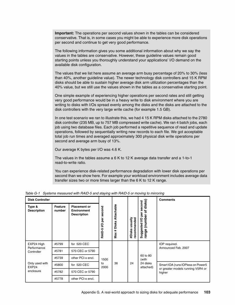
Table G-1 Systems measured with RAID-5 and staying with RAID-5 or moving to mirroring
Important: The operations per second values shown in the tables can be considered conservative. That is, in some cases you might be able to experience more disk operations per second and continue to get very good performance.
The following information gives you some additional information about why we say the values in the tables are conservative. However, these guideline values remain good starting points unless you thoroughly understand your applications’ I/O demand on the available disk configuration.
The values that we list here assume an average arm busy percentage of 20% to 30% (less than 40%, another guideline value). The newer technology disk controllers and 15 K RPM disks should be able to sustain higher average disk arm utilization percentages than the 40% value, but we still use the values shown in the tables as a conservative starting point.
One simple example of experiencing higher operations per second rates and still getting very good performance would be in a heavy write to disk environment where you are writing to disks with I/Os spread evenly among the disks and the disks are attached to the disk controllers with the very large write cache (for example 1.5 GB).
In one test scenario we ran to illustrate this, we had 4 15 K RPM disks attached to the 2780 disk controller (235 MB, up to 757 MB compressed write cache). We ran 4 batch jobs, each job using two database files. Each job performed a repetitive sequence of read and update operations, followed by sequentially writing new records to each file. We got acceptable total job run times and averaged approximately 300 physical disk write operations per second and average arm busy of 13%.
Our average K bytes per I/O was 4.6 K.
The values in the tables assume a 6 K to 12 K average data transfer and a 1-to-1 read-to-write ratio.
You can experience disk-related performance degradation with lower disk operations per second than we show here. For example your workload environment includes average data transfer sizes two or more times larger than the 6 K to 12 K range.
Disk Controller
RA
ID-5
I/O
per
sec
on
d
Max
# D
isks
Att
ach
able
#Dis
ks u
sual
lyre
com
men
ded
Su
gg
este
d I/
O p
er s
eco
nd
ra
ng
e (n
um
ber
of
dis
ks) Comments
Type & Description
Feature number
Placement or Environment Description
EXP24 High Performance Controller
Only used with EXP24 enclosure
#5799 for 520 CEC
1500to2000
36 24
60 to 80(with24 disksattached)
IOP required. Announced Feb. 2007
#5781 570 CEC or 5790
#5739 other PCI-x encl.
#5800 for 520 CEC Smart IOA (runs IOPless on Power5 or greater models running V5R4 or higher#5782 570 CEC or 5790
#5778 other PCI-x encl.
Appendix G. A real-world approach to sizing disks for adequate performance 103
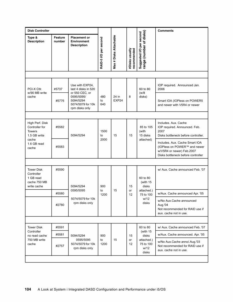
PCI-X Ctlr.w/90 MB write cache
#5737Use with EXP24, last 4 disks in 520 or 550 CEC, or 0595/5095/5094/52945074/5079 for 10k rpm disks only
480to640
24 in EXP24
8
60 to 80(w/8 disks)
IOP required. Announced Jan. 2006
#5776 Smart IOA (IOPless on POWER5 and newer with V5R4 or newer
High Perf. Disk Controller for Towers1.5 GB write cache1.6 GB read cache
#5582
5094/52941500to2000
15 15
85 to 105(with15 disksattached)
Includes. Aux. CacheIOP required. Announced. Feb. 2007Disks bottleneck before controller.
#5583Includes. Aux. Cache Smart IOA (IOPless on POWER™ and newer w/V5R4 or newer) Feb.2007Disks bottleneck before controller
Tower Disk Controller 1 GB read cache 750 MB write cache
#5590
5094/52940595/5095
5074/5079 for 10k rpm disks only
900to1200
1515or12
60 to 80(with 15
disksattached.)75 to 100
w/12 disks
w/ Aux. Cache announced Feb. '07
#5580 w/Aux. Cache announced Apr. '05
#2780w/No Aux.Cache announced Aug.'04Not recommended for RAID use if aux. cache not in use.
Tower Disk Controller no read cache 750 MB write cache
#5591
5094/52940595/5095
5074/5079 for 10k rpm disks only
900to1200
1515or12
60 to 80(with 15
disksattached.)75 to 100
w/12 disks
w/ Aux. Cache announced Feb. '07
#5581 w/Aux. Cache announced. Apr. '05
#2757w/No Aux.Cache anno/.Aug.'03Not recommended for RAID use if aux. cache not in use.
Disk Controller
RA
ID-5
I/O
per
sec
on
d
Max
# D
isks
Att
ach
able
#Dis
ks u
sual
lyre
com
men
ded
Su
gg
este
d I/
O p
er s
eco
nd
ra
ng
e (n
um
ber
of
dis
ks) Comments
Type & Description
Feature number
Placement or Environment Description
104 A Look at System i Integrated DASD Configuration and Performance under i5/OS
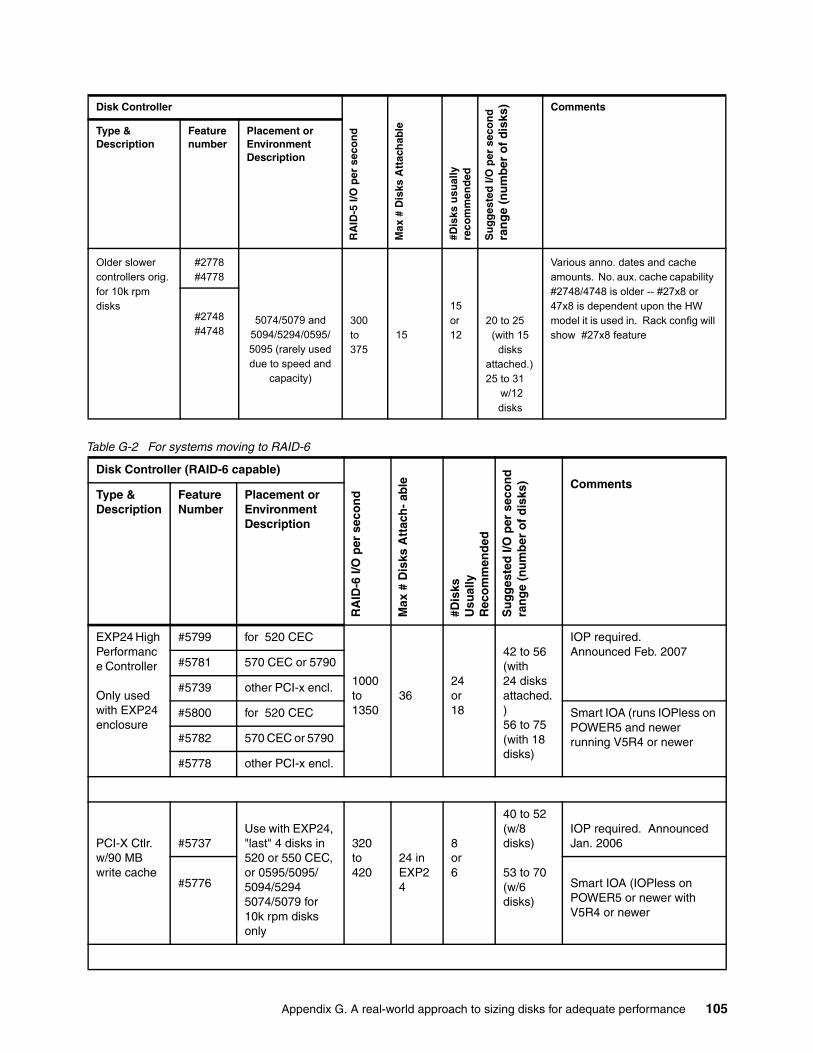
Table G-2 For systems moving to RAID-6
Older slower controllers orig. for 10k rpm disks
#2778#4778
5074/5079 and5094/5294/0595/5095 (rarely used due to speed and
capacity)
300to375
15
15or12
20 to 25(with 15
disksattached.)25 to 31
w/12 disks
Various anno. dates and cache amounts. No. aux. cache capability #2748/4748 is older -- #27x8 or 47x8 is dependent upon the HW model it is used in. Rack config will show #27x8 feature
#2748#4748
Disk Controller (RAID-6 capable)
RA
ID-6
I/O
per
sec
on
d
Max
# D
isks
Att
ach
- ab
le
#Dis
ksU
sual
lyR
eco
mm
end
ed
Su
gg
este
d I/
O p
er s
eco
nd
ra
ng
e (n
um
ber
of
dis
ks) Comments
Type & Description
Feature Number
Placement or Environment Description
EXP24 High Performance Controller
Only used with EXP24 enclosure
#5799 for 520 CEC
1000to1350
3624 or18
42 to 56(with24 disksattached.)56 to 75(with 18 disks)
IOP required. Announced Feb. 2007
#5781 570 CEC or 5790
#5739 other PCI-x encl.
#5800 for 520 CEC Smart IOA (runs IOPless on POWER5 and newer running V5R4 or newer#5782 570 CEC or 5790
#5778 other PCI-x encl.
PCI-X Ctlr.w/90 MB write cache
#5737Use with EXP24, "last" 4 disks in 520 or 550 CEC, or 0595/5095/5094/52945074/5079 for 10k rpm disks only
320to420
24 in EXP24
8or6
40 to 52 (w/8 disks)
53 to 70(w/6 disks)
IOP required. Announced Jan. 2006
#5776 Smart IOA (IOPless on POWER5 or newer with V5R4 or newer
Disk Controller
RA
ID-5
I/O
per
sec
on
d
Max
# D
isks
Att
ach
able
#Dis
ks u
sual
lyre
com
men
ded
Su
gg
este
d I/
O p
er s
eco
nd
ra
ng
e (n
um
ber
of
dis
ks) Comments
Type & Description
Feature number
Placement or Environment Description
Appendix G. A real-world approach to sizing disks for adequate performance 105
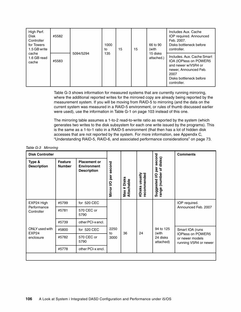
Table G-3 shows information for measured systems that are currently running mirroring, where the additional reported writes for the mirrored copy are already being reported by the measurement system. If you will be moving from RAID-5 to mirroring (and the data on the current system was measured in a RAID-5 environment, or rules of thumb discussed earlier were used), use the information in Table G-1 on page 103 instead of this one.
The mirroring table assumes a 1-to-2 read-to-write ratio as reported by the system (which generates two writes to the disk subsystem for each one write issued by the programs). This is the same as a 1-to-1 ratio in a RAID-5 environment (that then has a lot of hidden disk accesses that are not reported by the system. For more information, see Appendix C, “Understanding RAID-5, RAID-6, and associated performance considerations” on page 73.
Table G-3 Mirroring
High Perf. Disk Controller for Towers1.5 GB write cache1.6 GB read cache
#5582
5094/5294
1000to135
15 1566 to 90 (with 15 disks attached.)
Includes Aux. CacheIOP required. Announced Feb. 2007.Disks bottleneck before controller.
#5583Includes. Aux. Cache Smart IOA (IOPless on POWER5 and newer w/V5R4 or newer, Announced Feb. 2007Disks bottleneck before controller.
Disk Controller
Mir
ror
I/O p
er s
eco
nd
Max
# D
isks
A
ttac
hab
le
#Dis
ks u
sual
lyre
com
men
ded
Su
gg
este
d I/
O p
er s
eco
nd
ran
ge
(nu
mb
er o
f d
isks
)
Comments
Type & Description
Feature Number
Placement or Environment Description
EXP24 High Performance Controller
ONLY used with EXP24 enclosure
#5799 for 520 CEC
2250to3000
36 2494 to 125(with24 disksattached)
IOP required. Announced Feb. 2007
#5781 570 CEC or 5790
#5739 other PCI-x encl.
#5800 for 520 CEC Smart IOA (runs IOPless on POWER5 or newer models running V5R4 or newer
#5782 570 CEC or 5790
#5778 other PCI-x encl.
106 A Look at System i Integrated DASD Configuration and Performance under i5/OS
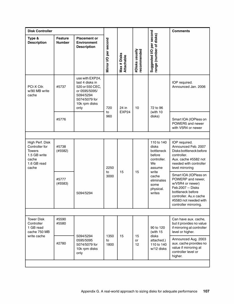
PCI-X Ctlr.w/90 MB write cache
#5737
use with EXP24, last 4 disks in 520 or 550 CEC, or 0595/5095/5094/52945074/5079 for 10k rpm disks only 720
to960
24 in EXP24
10 72 to 96(with 10 disks)
IOP required. Announced Jan. 2006
#5776 Smart IOA (IOPless on POWER5 and newer with V5R4 or newer
High Perf. Disk Controller for Towers1.5 GB write cache1.6 GB read cache
#5738(#5582)
5094/5294
2250to3000
15 15
110 to 140 disksbottleneck before controller.We assume write cache eliminates some physical. writes
IOP required. Announced Feb. 2007Disks bottleneck before controller.Aux. cache #5582 not needed with controller level mirroring
#5777(#5583)
Smart IOA (IOPless on POWERP and newer, w/V5R4 or newer) Feb.2007 -- Disks bottleneck before controller. Au.x cache #5583 not needed with controller mirroring.
Tower Disk Controller 1 GB read cache 750 MB write cache
#5590#5580
5094/52940595/50955074/5079 for 10k rpm disks only
1350to1800
15 15or12
90 to 120(with 15 disksattached.)110 to 140 w/12 disks
Can have aux. cache, but it provides no value if mirroring at controller level or higher.
#2780Announced Aug. 2003 aux. cache provides no value if mirroring at controller level or higher.
Disk Controller
Mir
ror
I/O p
er s
eco
nd
Max
# D
isks
A
ttac
hab
le
#Dis
ks u
sual
lyre
com
men
ded
Su
gg
este
d I/
O p
er s
eco
nd
ran
ge
(nu
mb
er o
f d
isks
)
Comments
Type & Description
Feature Number
Placement or Environment Description
Appendix G. A real-world approach to sizing disks for adequate performance 107
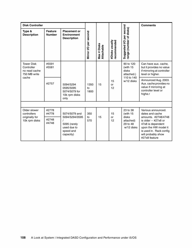
Tower Disk Controller no read cache 750 MB write cache
#5591#5581
5094/52940595/5095 5074/5079 for 10k rpm disks only
1350to1800
1515or12
90 to 120(with 15 disksattached.)110 to 140 w/12 disks
Can have aux. cache, but it provides no value if mirroring at controller level or higher.
#2757Announced Aug. 2003. Aux. cache provides no value if mirroring at controller level or highe.r
Older slower controllers originally for 10k rpm disks
#2778#4778 5074/5079 and
5094/5294/0595/5095 (rarely used due to speed and capacity)
350to570
1515or12
23 to 38 (with 15 disksattached)29 to 48 w/12 disks
Various announced. dates and cache amounts. #2748/4748 is older -- #27x8 or 47x8 is dependent upon the HW model it is used in. Rack config will probably show #27x8 feature
#2748#4748
Disk Controller
Mir
ror
I/O p
er s
eco
nd
Max
# D
isks
A
ttac
hab
le
#Dis
ks u
sual
lyre
com
men
ded
Su
gg
este
d I/
O p
er s
eco
nd
ran
ge
(nu
mb
er o
f d
isks
)
Comments
Type & Description
Feature Number
Placement or Environment Description
108 A Look at System i Integrated DASD Configuration and Performance under i5/OS
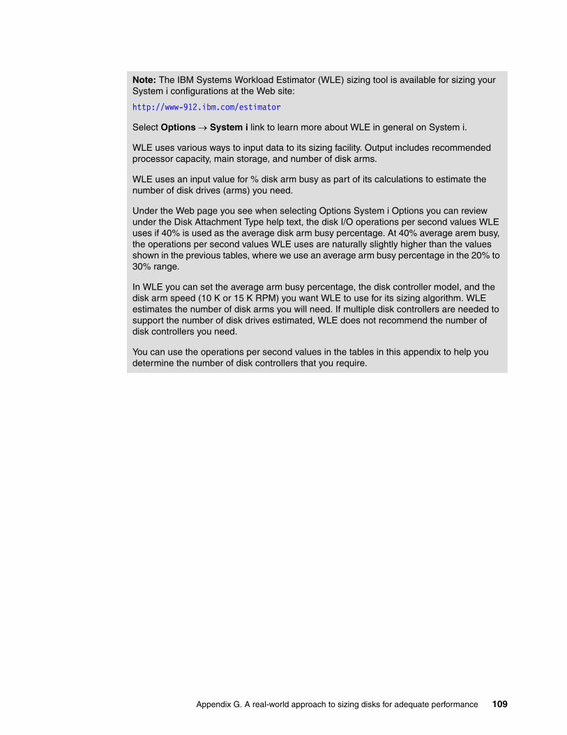
Note: The IBM Systems Workload Estimator (WLE) sizing tool is available for sizing your System i configurations at the Web site:
http://www-912.ibm.com/estimator
Select Options → System i link to learn more about WLE in general on System i.
WLE uses various ways to input data to its sizing facility. Output includes recommended processor capacity, main storage, and number of disk arms.
WLE uses an input value for % disk arm busy as part of its calculations to estimate the number of disk drives (arms) you need.
Under the Web page you see when selecting Options System i Options you can review under the Disk Attachment Type help text, the disk I/O operations per second values WLE uses if 40% is used as the average disk arm busy percentage. At 40% average arem busy, the operations per second values WLE uses are naturally slightly higher than the values shown in the previous tables, where we use an average arm busy percentage in the 20% to 30% range.
In WLE you can set the average arm busy percentage, the disk controller model, and the disk arm speed (10 K or 15 K RPM) you want WLE to use for its sizing algorithm. WLE estimates the number of disk arms you will need. If multiple disk controllers are needed to support the number of disk drives estimated, WLE does not recommend the number of disk controllers you need.
You can use the operations per second values in the tables in this appendix to help you determine the number of disk controllers that you require.
Appendix G. A real-world approach to sizing disks for adequate performance 109

110 A Look at System i Integrated DASD Configuration and Performance under i5/OS
Related publications
We consider the publications that we list in this section particularly suitable for a more detailed discussion of the topics that we cover in this paper.
IBM Redbooks Publications
For information about ordering these publications, see “How to get IBM Redbooks Publications” on page 111. Note that some of the documents referenced here might be available in softcopy only.
� IBM System i Overview: Models 515, 525, 550, 570, 595, and More, REDP-5052
� PCI and PCI-X Placement Rules for IBM System i models: i5/OS V5R3 and V5R4 (Fourth edition), REDP-4011
Online resources
These Web sites are also relevant as further information sources:
� System i and i5/OS Information Center
http://publib.boulder.ibm.com/iseries/
� Techdocs - the Technical Sales Library
http://www-03.ibm.com/support/techdocs/atsmastr.nsf/Web/TechDocs
(Use the keyword REDP3919 to find documents directly related to this paper.)
� System i Performance Capabilities Reference manual available at:
http://www.ibm.com/systems/i/solutions/perfmgmt/index.html
How to get IBM Redbooks Publications
You can search for, view, or download IBM Redbooks, IBM Redpapers, Technotes, draft publications and Additional materials, as well as order hardcopy Redbooks, at this Web site:
ibm.com/redbooks
Help from IBM
IBM Support and downloads
ibm.com/support
IBM Global Services
ibm.com/services
© Copyright IBM Corp. 2008. All rights reserved. 111

112 A Look at System i Integrated DASD Configuration and Performance under i5/OS

®
REDP-3919-00
INTERNATIONAL TECHNICALSUPPORTORGANIZATION
BUILDING TECHNICAL INFORMATION BASED ON PRACTICAL EXPERIENCE
IBM Redbooks are developed by the IBM International Technical Support Organization. Experts from IBM, Customers and Partners from around the world create timely technical information based on realistic scenarios. Specific recommendations are provided to help you implement IT solutions more effectively in your environment.
For more information:ibm.com/redbooks
Redpaper
A Look at System i Integrated DASD Configuration and Performance under i5/OS
Integrated disk configuration from a performance view
Lots of disk performance considerations and tips
Featuring the large read/write controllers
This IBM Redpaper publication summarizes integrated DASD configuration, DASD protection capabilities, and DASD performance through the disk controller hardware announced through 2007 and supported by i5/OS V5R3 and V5R4. For the hardware features that we cover in this paper, the information should also apply to later releases.
Note that this publication does not specifically address new disk adapters or any new i5/OS release announced after December 2007.
We feature the large read and write cache disk controllers announced during 1Q 2007 in this paper and include the following information:
� Specifications of the latest disk controller hardware (including physical placement of the disk controller cards within supporting hardware enclosures)
� RAID-5, RAID-6, and mirrored protection considerations� Positioning the available DASD hardware and protection features � Positioning the DASD component contribution to application
performance� General guidelines for DASD hardware choices based upon
estimated disk I/O operation rates with the different protection methods
� Analyzing DASD performance statistics gathered by i5/OS to see how the environment correlates with the general guidelines
The content of this paper is intended to be used by customers, IBM employees, IBM Business Partners, and others who desire or who need an understanding of disk subsystems in the System i product line.
Back cover