a lossless switch for data acquisition networksinspirehep.net/record/1426196/files/07366370.pdfa...
TRANSCRIPT

40th Annual IEEE Conference on Local Computer Networks LCN 2015, Clearwater Beach, Florida, USA
A Lossless Switch for Data Acquisition Networks
Grzegorz Jereczek, Giovanna Lehmann Miotto PH ATLAS DAQ and Trigger
CERN Geneva, Switzerland
{grzegorz.jereczekl giovanna.lehmann }@cern.ch
David Malone Hamilton Institute
Maynooth University Maynooth, Ireland
Miroslaw Walukiewicz Intel Corporation
Network Platforms Group Gdansk, Poland
miroslaw. walukiewicz@ intel.com
Abstract-The recent trends in software-defined networking (SDN) and network function virtualization (NFV) are boosting the advance of software-based packet processing and forwarding on commodity servers. Although performance has traditionally been the challenge of this approach, this situation changes with modern server platforms. High performance load balancers, proxies, virtual switches and other network functions can be now implemented in software and not limited to specialized commercial hardware, thus reducing cost and increasing the flexibility. In this paper we design a lossless software-based switch for high bandwidth data acquisition (DAQ) networks, using the ATLAS experiment at CERN as a case study. We prove that it can effectively solve the incast pathology arising from the many-to-one communication pattern present in DAQ networks by providing extremely high buffering capabilities. We evaluate this on a commodity server equipped with twelve 10 Gbps Ethernet interfaces providing a total bandwidth of 120 Gbps.
Index Terms-data acquisition, incast congestion, software switch.
I. INTRODUC TION
ATLAS [1] is a general-purpose particle detector designed to study particle collisions at the Large Hadron Collider (LHC) at CERN. One of the key components of the ATLAS, and other large-scale experiments, is a network, called the data acquisition network. It collects the outputs from all the instruments to reconstruct a physical process. In [2] , treating the ATLAS DAQ network as a case study, we identified and described a major challenge typical for the these networks: incast. It is perceived as a throughput collapse occurring when the number of servers sending data to clients increases past the ability of an Ethernet switch to buffer packets and has catastrophic consequences on the performance of the entire data acquisition system. We also explained strong analogues between incast in DAQ and datacenter networks (DCNs).
We indicated in [2] that increasing the available buffer space in the network is the most effective solution to the problem in case of the DAQ systems based on the TCP/IP and Ethernet technologies, but also the least scalable due to the high costs and availability of networking hardware with larger memory. In this paper we discuss whether this impediment can be possibly overcome by employing a group of commodity servers equipped with multiple Ethernet ports running a dedicated packet processing application. This gives the opportunity to greatly extend the buffering capabilities (limited only by the amount of the DRAM memory available
100 ROS PCs /
�
���
��
��
�//
OAQNetwork
��������-" ', ,
/ /
, ,
/ / /
, , ,
/
/ //
/
, , ,
ROS
" OCM
Fig. 1. The ATLAS DAQ system as of March 2015 and the multi-to-one communication pattern typical for DAQ networks. It is the cause of the incast congestion in the ToR and core layers of the network.
on the servers) and perform flexible optimisations tailored to the DAQ traffic patterns.
We continue to use the ATLAS experiment as a case study in this work. The conclusions are, however, not limited only to ATLAS but also many other networks susceptible to the problems arising from the many-to-one communication pattern as well as other data acquisition systems. The ATLAS DAQ network, having very demanding traffic characteristics, is a good environment to evaluate candidate technologies.
This paper is structured as follows. Section II gives an overview of the ATLAS data acquisition network, followed by a brief introduction to software switching, and concludes with related work. In Section III we discuss the characteristics of DAQ networks. We present our design of the lossless software switch in detail in Section IV. Experimental results performed with a small-scale prototype are provided in Section V, and discussed in Section VI, which also indicates areas for future exploration. We conclude our work in Section VII.
II. BACKGROUND AND MOTIVATION
A. Data acquisition networks and the TCP incast challenge
A DAQ network collects data from its sources and transports it to processing units for further analysis. The high level diagram of the ATLAS DAQ/HLT [3] is presented in Fig. l.
In the LHC nomenclature, particle collisions inside a detector are referred to as events. Their physical "fingerprints"
978-1-4673-6770-7/15/$31.00 ©2015 IEEE 552

are recorded by the detector, which is the data source for the DAQ system. Different data fragments corresponding to an event are striped over multiple read-out PCs, which constitute the Read-Out System (ROS). The ROS is an interface between the ATLAS-specific data acquisition components and commodity equipment. This is the entry point to the DAQ network, transporting event data to the filtering farm (HLT, High Level Trigger). The ROS sends data for a particular event to a single Processing Unit (PU), which is a worker process on a commodity server performing event reconstruction and analysis. There are multiple PUs on each server of the farm (working on independent events), but only one Data Collection Manager (DCM). The DCM requests event fragments from ROSes on the behalf of the PUs.
Today, the ATLAS DAQ/HLT system is based on 10 Gbps Ethernet ( lOGbE) network with TCP as transport layer protocol. The core of the network is built around two large routers. Around 100 ROS nodes are connected directly to them, while -2000 HLT nodes are organised in racks of at most 40 servers that connect to the core via top of rack (ToR) switches.
The specifics of data acquisition place an additional burden on the network subsystem. The burstiness of the traffic makes it difficult to handle with shallow-buffered network switches. A DCM requesting full event data from all the ROS PCs simultaneously causes a large traffic burst in the network (many-to-one communication pattern, see right side of Fig. 1). Although the response coming from a single ROS PC is relatively small, switches without sufficient buffer capacity drop some portion of the packets when the number of concurrent ROS responses increases. This leads to an order of magnitude higher event data collection time, which is caused by TCP timeouts [2] . This phenomenon is known as the TCP incast pathology [4] . Since the data collection time is one of the important parameters that need to be kept under control in a DAQ system, incast needs careful attention.
Many ways to approach the incast challenge have been proposed. We briefly reviewed some of them in [2] with the intention of possible adoption in DAQ. Most proposals focus on limiting the number of packets that are injected into the network. Although effective, especially in avoiding the incast congestion at ToR switches, large buffers are still required in the core of the network. The core routers need to sustain data flows from the ROS to all DCMs in the system. Incast avoidance by controlling the injection rate becomes very complex. The two routers of the current ATLAS DAQ network provide extremely large buffering capabilities [2] .
The demand on the buffering capacity will become even more critical when facing the future upgrades of the LHC [5] . Both the event sizes and rates will increase, thus making incast even more challenging. It is questionable whether traditional networking hardware will offer enough memory to sustain the increased requirements. Recent work in the area of the bufferbloat phenomenon [6] points out the excess of buffering in the network rather than scarcity experienced by DAQ. Specialist technologies like InfiniBand [7] or Ethernet Datacenter Bridging (DCB) [8] , which provide hardware-level
flow control and congestion control, can potentially operate with limited buffers even under many-to-one communication patterns. In this paper, however, we propose an alternative approach, which still allows using the commodity off-the-shelf (COTS) hardware.
B. Software switching
Packet processing in software on general purpose servers has recently become a real alternative for specialized commercial networking products thanks to new capabilities of commodity hardware and user space networking frameworks like Intel DPDK [9]. Commercial products like Brocade Vyatta Virtual Router [10] or offerings of 6WIND [11] prove the viability of this approach. With a combination of higher flexibility and features for a target application, a solution tuned for DAQ networks can be pursued. We investigate whether the expensive and feature-rich deep-buffered core routers could be replaced by a group of software switches running on servers equipped with multiple Ethernet ports. With a DAQ-optimized queuing discipline and buffering capabilities constrained solely by the amount of DRAM memory it is possible to operate a DAQ network without packet losses, thus avoiding the incast congestion without any controls on the injected traffic, beyond that arising naturally in a DAQ application. For this reason, we refer to them as loss less in the context of a DAQ system.
C. Related work
Software switches, Open vSwitch (OVS) [12] in particular, have already become an important part of cloud networking architectures providing network access for virtual machines (VMs) by linking virtual and physical network interfaces (hence called virtual switches) [13]. Our focus, however, lies in providing connectivity between physical hosts in the network with a data plane dedicated to DAQ applications. As shown in [14] a pure DPDK forwarding application currently provides the best achievable performance, comparable to those based on Netmap [15] and PF _RING [16] , which together with the Snabb Switch [17] are popular frameworks for softwarebased packet processing on standard x86 servers. The common goal of these frameworks is to optimize performance, which is achieved by providing their own drivers and libraries, not relying on the standard network stack of the kernel.
The recent developments in commodity hardware and software that enable high performance packet processing on general purpose servers are described in [l3] , which also provides performance evaluation and references to other packet forwarding applications. Extended analysis of potential hardware bottlenecks is available in [14]. Reference [18] gives a deeper insight into the DPDK library and compares it with Netmap and PF _RING. DPDK is also seen by [19] as a successor of the RouteBricks software router [20] and shows that saturating 80 Gbps for packet of 192 bytes or larger is practical.
Details of the architecture of the ATLAS data acquisition system are discussed in [21] , [22] . Characteristics of the DAQ traffic patterns on the example of the LHCb experiment at
553
CERN can be found in [23] . The example of an InfiniBandbased DAQ network is the CMS experiment [24]. We related the DAQ multi-to-one congestion with datacenter's TCP incast in [2]. For a recent review of work on TCP incast in datacenters, see [4] and references therein.
III. CH A R ACTERIS TICS OF DAQ NE TWORKS
In this section we highlight the key aspects of data acquisition networks, which distinguish them from the DCNs. These differences justify our choices with regard to the specific design of the software switch and, in the first place, the use of extremely large buffers. We also show that the potential bottlenecks of software switching [14] are insignificant in the case of traffic patterns typical for DAQ.
A. Farm size
The DAQ farm of the ATLAS experiment consists of -2000 servers filtering the LHC data and 100 servers in the ROS, compared to typical DCNs containing hundreds of thousands of servers [4] . The lookup table for packet switching is therefore relatively small and we can neglect the dependency of the performance on its size, which could normally cost additional CPU cycles of the software switch.
B. Workload
The DAQ networks are active during the data collection period, which for the LHC experiments is counted in months and years. They are exclusively dedicated to deliver the event data from the ROS to the filtering farm and isolated from any other flows, including the control traffic. The consequences are twofold. First, there are no flows in the DAQ whose latency could suffer from the large buffers in the network. Thus, bufferbloat [6] is not an issue. Second, the network can operate in a nearly static configuration for a very long time. This configuration can be set at the beginning of the run and tailored for the current data taking period. We showed already in [2] that disabling the TCP congestion control and setting a static value for the congestion window can be effective in solving the incast pathology in DAQ. We will now extend this approach in our design of the software switch.
C. Packet sizes
The forwarding performance of software switches is typically evaluated in the unit of packets per second (Pps) for the smallest packet size. This is due to the fact that the forwarding performance is mostly limited by the maximum packet rate and not the packet size. It is therefore easier to saturate a link with large packets. If there is a bottleneck in saturating a link of a software switch, it is always for small packets.
In DAQ, however, the event data traversing the network are generally large in relation to the Ethernet's minimum frame length of 64 B. For example, in ATLAS's 2015-2018 datataking period 1860 event data fragments of variable sizes around 1 kB are distributed across -100 ROS nodes [22]. This results in approximately 18.6 kB per single data source, compared to the Ethernet's maximum transmission unit (MTU)
of 1500 B. For this reason and because of the limits of our traffic generators, we will not analyze the performance of our prototype for lower MTUs. Saturating 8 x 10GbE interfaces with smaller packets was already demonstrated in [19].
D. Switching latency
One of the important performance indicators of a switch is its latency. It is particularly critical in high frequency trading or high performance computing. In data acquisition, due to the large event sizes, the total data collection latency is dominated by the packetization delay. It takes approximately 1.5 ms to send the entire event, as described above, over a 10 Gbps link. It will be even higher considering that multiple events traverse the network simultaneously. Minimizing the switching latency is therefore not critical in DAQ as long as it is kept within a reasonable range.
E. Data collection time and jitter
The data collection latency is the time it takes to transfer the event data between the ROS and HLT, and is dominated in general by the packetization delay as already explained. Its mean and variance or, in other words, jitter, are factors important to the performance of the entire DAQ system. Blocking the PUs from processing because of an increased collection time translates into lost CPU time, which can lead to underutilization of the compute farm and a reduced overall event processing rate. As we explained in [2] , the main reason for an increased mean collection latency and jitter is the multi-to-one communication pattern leading to the TCP incast pathology. The TCP timeouts, in particular, caused by overflows of the buffers in the network, introduce at least 200 ms delay to the event collection, which increase the mean and jitter radically. In this paper we focus our performance evaluation on the ability of our design to eliminate the costly packet drops in the network.
IV. DESIGN
The main rationale behind our design of the software switch for data acquisition networks is to eliminate packet drops caused by incast while maintaining high throughput. Because of the large size of the events, less effort can be put into minimizing the processing time of a single packet. We use DPDK as the underlying packet processing framework to perform packet I/O between user-level threads and the network interface controllers (NICs). The high level design is presented in Fig. 2. The decision to use DPDK is motivated by the its exhaustive documentation and a broad set of examples. The L3FWD application, in particular, delivered full forwarding performance without any difficulty and became a basis for us to design our own switching application.
The core of the design lies in the idea of implementing dedicated buffers to each DCM in the system. Event data sent from different ROSes, but targeting the same DCM, are put into a single queue. With this approach the buffers can be sized precisely, traffic can be shaped on a per DCM basis, and fairness across all DCMs can be guaranteed.
554
NIC 0 Rx Queue 0 111111111111 Rx Queue 1
Default Thread - Data Flow Detection
NICO 111111111111 Tx Queue 0
Rin Buffers �UIIIIDIl Tx Queue 1
Rx Queue N
Rx Queue 0 [llglIgllgllglIRllj Rx Queue 1 IT
Rx Queue N
Rx Queue 0 [I IglIgl Igl IgliBI 11 Rx Queue 1 IT
Rx Queue N I Mgmt Thread I
Tx Queue 2
�I�II�I �II �II �II�II Tx Queue 0
....... Tx Queue 1
Tx Queue 2
111111111111 Tx Queue 0
III1IIIIIIII Tx Queue 1
Tx Queue 2
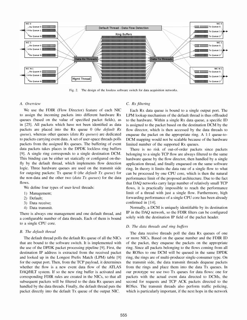
Fig. 2. The design of the lossless software switch for data acquisition networks.
A. Overview
We use the FDIR (Flow Director) feature of each NIC to assign the incoming packets into different hardware Rx queues (based on the value of specified packet fields), as in [25]. All packets which have not been identified as data packets are placed into the Rx queue 0 (the default R.x queue), whereas other queues (data Rx queues) are dedicated to packets carrying event data. A set of user-space threads polls packets from the assigned Rx queues. The buffering of event data packets takes places in the DPDK lockless ring buffers [9] . A single ring corresponds to a single destination DCM. This binding can be either set statically or configured on-thefly by the default thread, which implements flow detection logic. Three hardware queues are used on the transmit side for outgoing packets: Tx queue 0 (the default Tx queue) for the non-data and the other two (data Tx queues) for the data flows.
We define four types of user-level threads:
1) Management; 2) Default; 3) Data receive; 4) Data transmit.
There is always one management and one default thread, and a configurable number of data threads. Each of them is bound to a single CPU core.
B. The default thread
The default thread polls the default Rx queue of all the NICs that are bound to the software switch. It is implemented with the use of the DPDK packet processing pipeline [9]. First, the destination IP address is extracted from the received packet and looked up in the Longest Prefix Match (LPM) table [9] for the output port. Then, from the TCP payload, it determines whether the flow is a new event data flow of the ATLAS DAQIHLT system. If so the new ring buffer is activated and corresponding FDIR rules are created in the NICs, so that all subsequent packets will be filtered to the data Rx queues and handled by the data threads. Finally, the default thread puts the packet directly into the default Tx queue of the output NIC.
C. Rx filtering
Each Rx data queue is bound to a single output port. The LPM lookup mechanism of the default thread is thus offloaded to the hardware. Within a single Rx data queue, a specific ID is assigned to the packet based on the destination DCM by the flow director, which is then accessed by the data threads to enqueue the packet on the appropriate ring. AI: 1 queue-toDCM mapping would not be scalable because of the hardware limited number of the supported Rx queues.
There is no risk of out-of-order packets since packets belonging to a single TCP flow are always filtered to the same hardware queue by the flow director, then handled by a single application thread, and finally enqueued on the same software ring. In theory it limits the data rate of a single flow to what can be processed by one CPU core, which is then the natural performance limit of the proposed architecture. Due to the fact that DAQ networks carry large number of relatively small TCP flows, it is practically impossible to reach the performance limit of a thread with just a single flow. Furthermore, high forwarding performance of a single CPU core has been already confirmed in [14].
Normally, a DCM is uniquely identifiable by its destination IP in the DAQ network, so the FDIR filters can be configured solely with the destination IP field of the packet header.
D. The data threads and ring buffers
The data receive threads poll the data Rx queues of one or more NICs. Based on the queue number and the FDIR ID of the packet, they enqueue the packets on the appropriate ring. Since all packets belonging to the flows coming from all the ROSes to one DCM will be queued in the same DPDK ring, the rings are of multi-producer single-consumer type. On the transmit side, the data transmit threads dequeue packets from the rings and place them into the data Tx queues. In our prototype we use two Tx queues for data flows: one for packets with the actual event data directed to DCMs, the second for requests and TCP ACK packets directed to the ROSes. The transmit threads also perform traffic policing, which is particularly important, if the next hops in the network
555
have limited buffering/bandwidth capabilities. In order to avoid incast in those network stages as well, rate limiting can be applied. Since the event data targeted to a particular DCM is queued in a dedicated buffer, rate limitation can be performed very effectively on per destination DCM basis. Each data transmit thread serves the data Tx queues of one or more NICs.
If a particular DCM ring remains empty for a predefined period of time it can be deactivated. In this case, it can be reused by the default thread for any newly detected data flows.
E. Memory management and thread assignment policy
In order to achieve the highest performance of our switch, we follow the DPDK recommendations, especially with regard to NUMA-aware (Non-Uniform Memory Access) object allocation in memory and the use of huge page tables. The data Rx and Tx queues are spread across the available data threads to match the NUMA-node of the corresponding NIC, if possible.
F Summary
Our design choices are closely correlated with the characteristics of DAQ networks, which were discussed in Section III.
Because of the relatively small size of the entire ATLAS DAQ/HLT farm the lookup mechanisms for packet forwarding and data flow filtering can be offtoaded to the hardware flow director. A single Intel 82599 controller supports up to 8190 perfect match flow director filters and 128 Rx queues [26]. Furthermore, in order to provide connectivity of the whole system, a group of interconnected software switches is required, further increasing the quota of the available hardware filters.
The link bandwidth of a DCM is known at the start of the run of the experiment and does not change over time. Appropriate rate limits can be thus applied at the software switch thanks to the large, per DCM buffers. This is particularly important, if DCMs are connected by a ToR switch with limited buffers to the DAQ network. The incast pathology can be avoided at each network layer, keeping the data collection latency low and without jitter. The size of a ring buffer can be set to match the traffic targeting a single DCM.
Since many fewer CPU cycles are required to saturate a 10 Gbps with large packets, the number of data threads required to provide full bandwidth can be less than the number of available CPU cores on a server depending on the average packet length. The number of threads can be configured to match the expected performance leaving additional CPU cores to perform other tasks.
V. EVALU ATION
We evaluate the implementation of the lossless software switch with a small-scale DAQ setup using the ATLAS DAQ software in emulation mode. First, we verify the offered bandwidth in an all-to-all communication scenario. Second, we evaluate the buffering capability and determine its effectiveness in solving incast in the typical for DAQ many-to-one scenario.
Port 1 Port 2 Port 3 Port 4
Port 5 Port 6
�"'-"'�"'+I���g� �
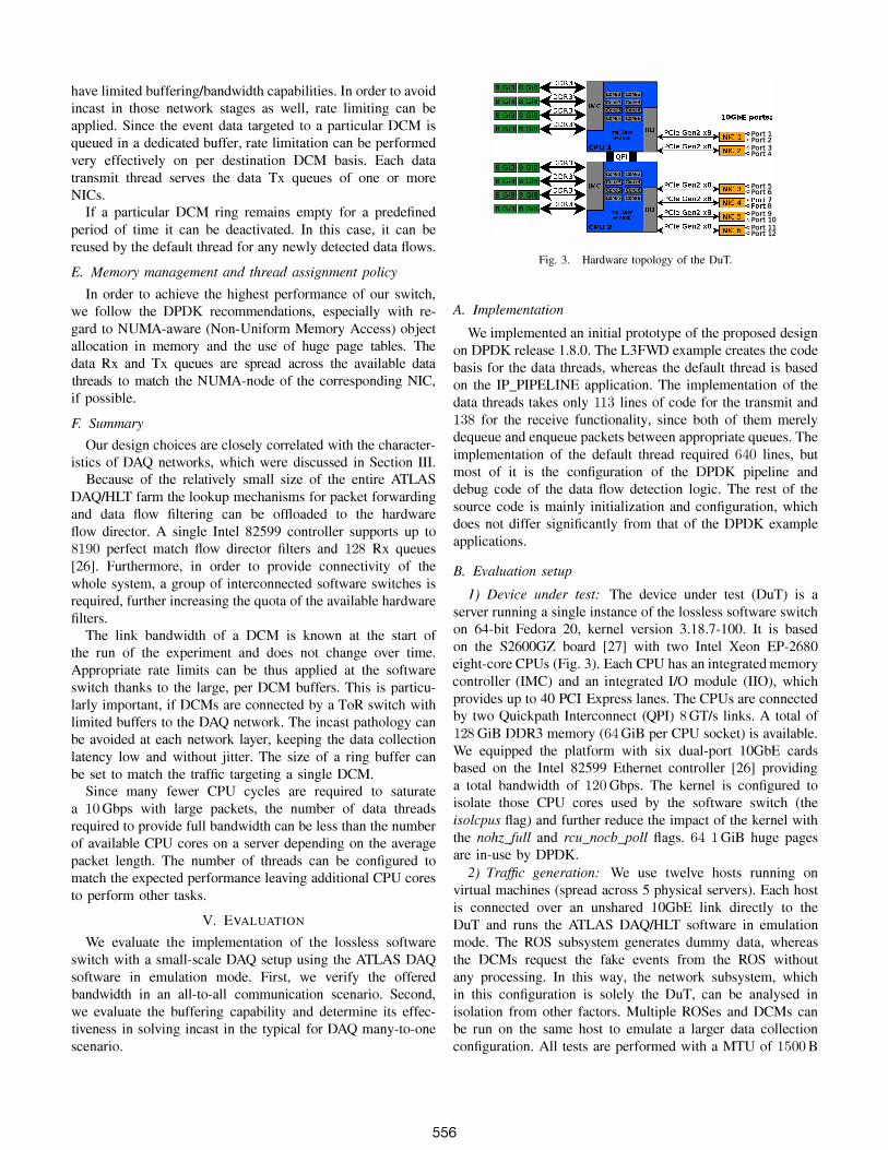
Fig. 3. Hardware topology of the DuT.
A. Implementation
Port 9 Port 10 Port 11 Port 12
We implemented an initial prototype of the proposed design on DPDK release 1.8.0. The L3FWD example creates the code basis for the data threads, whereas the default thread is based on the IP _PIPELINE application. The implementation of the data threads takes only 113 lines of code for the transmit and 138 for the receive functionality, since both of them merely dequeue and enqueue packets between appropriate queues. The implementation of the default thread required 640 lines, but most of it is the configuration of the DPDK pipeline and debug code of the data flow detection logic. The rest of the source code is mainly initialization and configuration, which does not differ significantly from that of the DPDK example applications.
B. Evaluation setup
1) Device under test: The device under test (DuT) is a server running a single instance of the lossless software switch on 64-bit Fedora 20, kernel version 3.18.7-100. It is based on the S2600GZ board [27] with two Intel Xeon EP-2680 eight-core CPUs (Fig. 3). Each CPU has an integrated memory controller (IMC) and an integrated I/O module (110), which provides up to 40 PCI Express lanes. The CPUs are connected by two Quickpath Interconnect (QPI) 8 GT/s links. A total of 128 GiB DDR3 memory (64 GiB per CPU socket) is available. We equipped the platform with six dual-port 10GbE cards based on the Intel 82599 Ethernet controller [26] providing a total bandwidth of 120 Gbps. The kernel is configured to isolate those CPU cores used by the software switch (the isolcpus flag) and further reduce the impact of the kernel with the nohzJull and rcu_nocb-fJoll flags. 64 1 GiB huge pages are in-use by DPDK.
2) Traffic generation: We use twelve hosts running on virtual machines (spread across 5 physical servers). Each host is connected over an unshared 10GbE link directly to the DuT and runs the ATLAS DAQ/HLT software in emulation mode. The ROS subsystem generates dummy data, whereas the DCMs request the fake events from the ROS without any processing. In this way, the network subsystem, which in this configuration is solely the DuT, can be analysed in isolation from other factors. Multiple ROSes and DCMs can be run on the same host to emulate a larger data collection configuration. All tests are performed with a MTU of 1500 B
556
as already explained. A single DCM does not request another event before it receives all fragments of the previous event from all available ROSes. Data collection latency of a single event is understood as the timespan between sending the first request to the ROS and receiving the last fragment from the ROS. We disable dynamic TCP congestion control in all ROS hosts and instead use a static sender congestion window [2]. Unless otherwise stated, the window is set to a very large value so that each ROS response is not rate limited by TCP, further increasing the incast effect. It also allows us to evaluate the performance of our prototype without the influence of the congestion control and test in the best scenario from the viewpoint of data acquisition pushing simply all the available data on to the wire. In other words, there is no traffic injection control and the optimizations discussed in our earlier study [2] are not in place for the most of the experiments throughout this work. It should be noted here that our goal is not a direct comparison with traditional switches, which can provide the same bandwidth with appropriate congestion control.
The presented values for latency, throughput, and bandwidth are averages over approximately 120 s in all cases.
C. Maximum achievable bandwidth
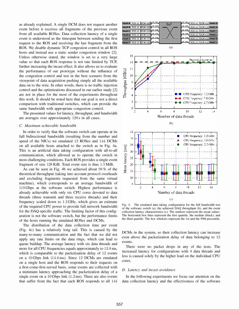
In order to verify that the software switch can operate at its full bidirectional bandwidth (resulting from the number and speed of the NICs) we emulated 12 ROSes and 144 DCMs on all available hosts attached to the switch as in Fig. 4a. This is an artificial data taking configuration with all-to-all communication, which allowed us to operate the switch in most challenging conditions. Each ROS provides a single event fragment of size 128 KiB. Total event size is thus 1.5 MiB.
As can be seen in Fig. 4b we achieved about 98 % of the theoretical throughput (taking into account protocol overheads and excluding fragments requested from the same virtual machine), which corresponds to an average bandwidth of 118 Gbps at the software switch. Highest performance is already achievable with only six CPU cores devoted to data threads (three transmit and three receive threads) and their frequency scaled down to 1.2 GHz, which gives an estimate of the required CPU power to provide full network bandwidth for the DAQ-specific traffic. The limiting factor of this configuration is not the software switch, but the performance limits of the hosts running the emulated ROSes and DCMs.
The distribution of the data collection time per event (Fig. 4c) has a relatively long tail. This is caused by the many-to-many communication and the fact that we did not apply any rate limits on the data rings, which can lead to queue buildup. The average latency with six data threads and more for all CPU frequencies equals approximately to 13.8 ms, which is comparable to the packetization delay of 12 events on a 10 Gbps link (14.6 ms). Since 12 DCMs are emulated on a single host and the ROS responds to their requests on a first-come-first-served basis, some events are collected with a minimum latency approaching the packetization delay of a single event on a 10 Gbps link (1.2 ms). There are also events that suffer from the fact that each ROS responds to all 144
IHoetA Res xl IIDeM X12J � OuT �I Res xl IIDeM x12 Hoat G
IHoetB Res xl IIDeM X12] �
X 010 GbEcl ROS xl oeM x12 HoatH
Hoate Res xl IIDeM X12J� � Res xl oeM x12 Moat I IHoat D Res xl IIDeM X12J � � ROS xl DeM x12 HoatJ IHoatE HoetF
u;' ...... � 2 :; 0.. ..c OIl :::l 0
1: E-<
Res xl IIDeM X12] � � Res xl oeM x12 HoatK Res xl IIDeM x121 � � Res xl oeM x12 HoatL
16
14
12
10
8
6
4
2
0 2
(a)
Theoretical maximum'
. . . . . .................................. , I , I •
...... ;. ...... ; . . . . . . . ...... CPU frequency: 1.2 GHz ........ CPU frequency: 2.0 GHz
..... -: ....... ; . . . . . . ..... CPU frequency: 2.7 GHz
4 6 8 10 12 N urn ber of data threads
(b)
14
45r-�. 1 ----�1r----r-1 ---r----�---'-----r-' • CPU frequency: 1.2 GHz
40 - .: ...... ; ...... :...... • CPU frequency: 2.0 GHz
u;' 35 -I .... i ...... ;. . . . .. • CPU frequency. 2.7 GHz
S : : : : : :
;>. 30 - - . - - - ! - - - - - - : - - - - - - : - - - - - - - : - - - - - - � - - - - - - � - -() . . . . . .
i: 25 . . . . .
] : : : : : :
�� =::::::: :. ; "::I!r: ::rD:::rll::rlI::II1 10 - · -: - - .... > .. m .. ·m .. ·m .. ·m .. m 5 ��1----�1----�1----�1----�1----�1----�1�
2 4 6 8 10 12 14 N urn ber of data threads
(c)
Fig. 4. The emulated data taking configuration for the full bandwidth test of the software switch (a). the achieved DAQ throughput (b). and the event collection latency characteristics (c). The markers represent the mean values. The horizontal box lines represent the first quartile, the median (black). and the third quartile. The box whiskers represent the 1st and the 99th percentile.
DCMs in the system, so their collection latency can increase even above the packetization delay of data belonging to 12 events.
There were no packet drops in any of the tests. The increased latency for configurations with 4 data threads and less is caused solely by the higher load on the individual CPU cores.
D. Latency and incast avoidance
In the following experiments we focus our attention on the data collection latency and the effectiveness of the software
557

';;' S :>-. u == � � == � <l) �
Vl
== 0
'u:J Vl
.§ Vl
== � b <l) ;....
Q.. U E-<
1000
...
100
, , ,
/-• • •
*
cwnd: 4 cwnd: 16 cwnd: 64 cwnd: 5000
� !k.� !� • •
10 �-L--------�--��--��--128 512 768 1024 4096
Ring size per DCM [no. of packets]
(a)
/-800000 -- cwnd:4
........ cwnd: 16 ........ cwnd: 64
600000 ........ cwnd: 5000
400000 - - - - - � - - . - -
200000 ...........
O��====�==�==�==/-�� __ � 128 512 768 1024 4096
Ring size per DCM [no. of packets]
(b)
Fig. 5. Data collection latency (a) of the same configuration as in Fig. 4a. but with rate limiting applied to every destination DCM of approximately O.S Gbps. The markers represent the mean values. The horizontal box lines represent the first quartile. the median (black), and the third quartile. The box whiskers represent the 1st and the 99th percentile. (b) shows the total number of TCP retransmissions in a 120 s period of data collection.
switch in incast avoidance. The data receive threads were configured to drop packets, if there was no space available in the ring of the corresponding destination DCM.
1) Full system load: In this configuration, we continue with the same setup as depicted in Fig. 4a, but we apply a rate limit to each destination DCM. This is achieved simply by restricting the transmit data threads to put no more than 32 packets from a single ring buffer to a single Tx queue every 500 J..Is, which limits each DCM to approximately 0.78 Gbps at the software switch. This approach shows how incast could be avoided in a situation when DCMs are connected with slow links to a ToR switch. By limiting the rate we ensure that the ToR switch buffers are not overrun and the packets are buffered at the software switch instead.
The latency characteristics and the corresponding TCP performance are shown in Fig. 5. The tests were performed for various combinations of the sender's congestion window (cwnd) and the per DCM ring sizes (in packets). Data of a single event that needs to traverse the software switch requires
approximately 990 TCP segments over 11 TCP flows to a single DCM. As can be seen in Fig. 5a, a small congestion window of merely 4 packets is not prone to incast (no TCP retransmissions) at any ring size as latency remains low regardless of ring size. ROSes respond to a single DCM with only 4 packets at a time, so no more than 44 packets need to be queued in a single ring of the switch. Although incast is avoided, the mean latency of event data collection is increased compared to higher values of cwnd. Increasing the window while maintaining small packet buffers (i.e. 128 or 512 packets per DCM) triggers incast and results in a very high mean of the data collection latency. In the optimum operating range, with very large congestion windows and long queues, the latency remains at its minimum value of 17.2 ms with low jitter, and without any TCP retransmissions. The packetization delay of the entire event data on a link limited to 0.78 Gbps, including protocol overheads, equals to 15.6 ms and gives the lower limit on the minimum data collection time .
The direct effect of the collection latency is the maximum achievable event rate of the system. In the optimum switch configuration the DAQ throughput achieves 11.4 GiB/s (80 % of the theoretical maximum and a bandwidth of 96 Gbps at the software switch). The maximum from the previous section is not reached because of the applied rate control and the performance limitations of the traffic generation setup. With the limited congestion window (e.g. cwnd = 4) the throughput reduces to 8.2 GiB/s.
With the total of 144 DCMs in this configuration 144 ring queues are active in the software switch. For the single ring size of 4096 packets and 2048 B of maximum packet size configured at the switch, the total packet buffer space equals to 1.12 GiB.
2) Increased burstiness with a single DCM: We now increase the burstiness of the traffic by increasing the number of emulated ROSes to 110 (Fig. 6a), leaving the congestion window at 5000. Only a single DCM is used in this test and it is rate limited to 0.78 Gbps. The total event size is now 13.75 MiB (single ROS fragment size remains the same) and the packetization delay of the entire event, with protocol overheads, is 156 ms. The event size corresponds to approximately 9790 TCP segments over 110 TCP flows.
The latency characteristics and the corresponding TCP performance are presented in Fig. 6b, again as a function of the ring buffer size. Starting with a length of 9000 packets (nearly the number of packets required to carry the entire event) there is no jitter and the mean latency remains at 159 ms, very close to the packetization delay. Reducing the ring size below 9000 triggers incast with high jitter and mean latency, which are caused by the high number of TCP retransmissions. Because of the large bursts, the DCM queue fills up and packets are dropped by the switch. For queues below 5000 every collected event suffers from at least one TCP timeout of a minimum value of 200 ms. The increase of the retransmissions between the first two data points is caused by the higher event rate achieved by the system. In other words, the average retransmission rate per event is lower for the second data point.
558

IHoat A LROS Xl� � OuT �LROSXl� HostU IHost B [ROS XI6] �
X �10 GbEal ROS xl0 HostH
[Hoste ROSxl0 � � ROS xl0 Moat. IHost DLROS xl� � � ROS xlO HostJ IHost E [ROS XI6] � � ROS xl0 HostK IHoat F ROS xl0 � � DeM XIJ Host L
(a)
1000 .-----.-----,----,,----,,----,-----,--,
Vl
c: 0
'Vi Vl
.§ Vl
c: � b � ....
� U E-<
600
400
200 156
. . . . . . . . . . . . . . . . . . . . . . . . . . . . . . . . . . - - - - - - - - - - - - -. . . .
l00 �----�----�--��--��--�----�� 2000
4000
3000
2000
1000
0 2000
4000 6000 8000 10000 12000 14000 Ring size per DCM [no. of packets]
(b)
4000 6000 8000 10000 12000 14000 Ring size per DCM [no. of packets]
(c)
Fig. 6. The emulated data taking configuration (a) for a scenario with single DCM and no ROSes. (b) gives the event collection latency characteristics. The markers represent the mean values. The horizontal box lines represent the first quartile, the median (black), and the third quartile. The box whiskers represent the 1st and the 99th percentile. (c) shows the total number of TCP retransmissions in a 120 s period of data collection.
VI. DISCUSSION AND OU TLOOK
Our results show that the proposed design of the software switch can be configured to match the specifics of a DAQ system and operate at full available bandwidth with low jitter and without packet drops, thus eliminating incast. This is also true under heavy congestion and for packets arriving in extremely large bursts, which we have shown by disabling the TCP congestion control and leaving the congestion window practically limitless. These results are possible thanks to the available amount of system memory that can be used as packet buffers and the architecture of modern CPUs, which
provide the necessary performance. Equally important is the presence of packet processing frameworks, which allow the design of dedicated network applications tailored for a specific configuration, like our lossless software switch for the ATLAS DAQ network.
In [2] we analyzed whether the variety of algorithms proposed to avoid TCP incast in datacenter could be also considered for DAQ networks. Most of them focus on lowering the packet injection rate into the network and thus reducing the pressure on the switch buffers. The same approach is taken by [22] in the present ATLAS DAQ/HLT system. A simple credit-based mechanism called traffic shaping obtains results that match or exceed the alternative proposals as described in [2] . On the other hand, [22] also shows that larger buffers tend to provide better performance in terms of achievable minimum latency thanks to the better link utilization. The well-known Data Center TCP (DCTCP) protocol, which leverages the Explicit Congestion Notification (ECN) mechanism to keep the queues small while maintaining high throughput, provides comparable latencies as deep buffered switches [28]. It is argued, however, that the short-message traffic is penalized due to the queue buildup phenomenon. This drawback is avoided with our design thanks to the dedicated queues for incastsensitive flows. Furthermore, DCTCP fails to avoid incast if there are so many senders that the packets sent in the first round trip time (RTT) overflow the buffers, as already indicated by the authors [28]. This situation is not uncommon for high-bandwidth low-latency DAQ networks like the one of the ATLAS DAQIHLT system [2]. For this reason we turn our focus to a solution, which could provide flexible and costcompetitive buffering capabilities. Our proposal also makes it possible to use a simple unreliable protocol like UDP, which may be advantageous in some DAQ systems.
We used the ATLAS experiment as a case study, but our findings can be applied to other DAQ networks and possibly other networks dealing with the many-to-one communication pattern. Particularly in environments with relatively constant mean load, already a simple static configuration with predefined congestion windows and matching buffer sizes in the network provide good performance under incast congestion. Queueing algorithms can be easily adapted to provide the best results for the given network topology and traffic patterns. As an example, we use a dedicated queue for each DCM to enforce a rate limit. With this approach we can treat the network as part of our software infrastructure and optimize it like any other computer program.
Our findings are still based on a small-scale prototype with twelve lOGbE ports. We proved the feasibility of the approach, which is the goal of this work. Bandwidth-wise, however, the offered load of 120 Gbps is already comparable with the present system, which is designed to sustain a throughput of several lOGiB after the restart of the LHC in 2015 [22]. Nevertheless, the DAQ network of the ATLAS experiment requires full connectivity between the ROS and the HLT farm, which is now provided by the classical architecture with two large routers at the core of the network. Further investigation
559

is needed to determine whether this classical topology could be eventually replaced by a number of interconnected software switches and what the resulting port density would be. Since there are physical limits on the number of NICs that can be installed in a single server and the physical space available at an experiment's site is also limited, the achievable port density becomes an important factor. This architecture will have to sustain throughput that will be two or more orders of magnitudes larger for the future upgrades of the experiment. No less important are aspects as administration, configuration, fault tolerance and load balancing, which also require careful attention.
We have already shown that our switch does not require all CPU cores at their maximum frequency to provide full performance. This is the first step towards the analysis of the energy consumption, which is an important consideration as well. On the other hand, since only some fraction of the CPU power is consumed by the software switch, there is the potential of integration switching and processing elements in a single server.
VII. CONCLUSION
In this paper we proposed the design of a lossless softwarebased switch targeting high bandwidth data acquisition networks with the aim of preventing TCP throughput collapse due to incast. For an application that requires an aggregate bandwidth of less than 120 Gbps and its bursts size fitting within the memory of the software switch, being 128 GiB, our switch design should result in lossless operation. And, importantly, controls on the injected traffic are not required.
First, we characterized DAQ networks and showed that the potential impediments of software switching, like latency or the offered bandwidth for small packets, are not critical to the performance of data acquisition systems. Instead, the nearly limitless memory and the flexibility of a software switch allows us to design a dedicated software switch with enormous packet buffers that could be considered as a potential replacement for the expensive feature-rich core routers in the future upgrades of the DAQ systems at the LHC. We verified the correctness of this hypothesis on a real hardware providing 120 Gbps bandwidth. Emulating data taking sessions with the ATLAS DAQ software, we effectively prevented incast maintaining the system bandwidth with 144 data collectors receiving data on a total of 1584 TCP flows through a single software switch. The small prototype already reaches, bandwidth-wise, figures comparable to the requirements of the existing system. This paper does not demonstrate yet that such an architecture will scale by two or more orders of magnitude for the future upgrades of the ATLAS experiment, which is a further line of research that will need to be demonstrated. Besides, there are several other aspects requiring further exploration, ranging from administration to port density and power consumption.
ACKNOWLEDGMENT
This research project has been supported by a Marie Curie Early European Industrial Doctorates Fellowship of the European Community's Seventh Framework Programme under contract number (PITN-GA-2012-316596-ICE-DIP).
REFERENCES
[I] The ATLAS Collaboration, "The ATLAS Experiment at the CERN Large Hadron Collider," Journal of Instrumentation, vol. 3, no. OS, p. SOS003, 200S.
[2] G. lereczek et aI., "Analogues between tuning TCP for data acquisition and datacenter networks," in Proc. IEEE ICC, 2015, to be published.
[3] The ATLAS Collaboration, "ATLAS high-level trigger, data-acquisition and controls: Technical design report," Geneva, Tech. Rep. ATLASTDR-16 CERN-LHCC-2003-022, 2003.
[4] Y. Zhang et aI., "On architecture design, congestion notification, TCP in cast and power consumption in data centers," Communications Surveys & Tutorials, vol. 15, no. 1, pp. 39-64, 2013.
[5] A. Di Meglio et aI., "CERN openlab whitepaper on future IT challenges in scientific research," May 2014. [Online]. Available: http://dx.doi.org/ I O. 52SlIzenodo. S765
[6] 1. Gettys et aI., "Bufferbloat: Dark buffers in the Internet," Queue, vol. 9, no. 11, 2011.
[7] E. G. Gran et aI., "First experiences with congestion control in InfiniBand hardware," in Proc. IEEE IPDPS, 2010, pp. 1-12.
[S] S. S. Reinemo et al., "Ethernet for high-performance data centers: On the new IEEE datacenter bridging standards," IEEE Micro, vol. 30, no. 4, pp. 42-51, 2010.
[9] Intel DPDK: Data plane development kit. [Online]. Available: http://dpdk.org/
[10] V yatta vRouter. [Online]. Available: http://www.brocade.com [11] 6WIND. [Online]. Available: http://www.6wind.com [12] Open vSwitch. [Online]. Available: http://openvswitch.org/ [13] P. Emmerich et al., "Performance characteristics of virtual switching,"
in Proc. IEEE CloudNet, 2014, pp. 120-125. [14] P. Emmerich et aI., "Assessing soft- and hardware bottlenecks in PC
based packet forwarding systems," ICN 2015, p. 90, 2015. [15] L. Rizzo, "Netmap: a novel framework for fast packet I/O," in Proc.
USENIX, 2012, pp. 101-112. [16] PF _RING. [Online]. Available: http://www.ntop.org/products/pCring/ [17] Snabb switch. [Online]. Available: http://www.snabb.co [IS] D. Scholz, "A look at Intels dataplane development kit," in Network
Architectures and Services (NET), vol. NET-2014-0S-1, 2014, pp. 115-122.
[19] D. Zhou et al., "Scalable, high performance Ethernet forwarding with CuckooSwitch," in Proc. ACM CoNEXT, 2013, pp. 97-IOS.
[20] K. Fall et aI., "Routebricks: enabling general purpose network infrastructure," ACM SIGOPS Operating Systems Review, vol. 45, no. 1, pp. 112-125,2011.
[21] 1. G. Panduro Vazquez, "The ATLAS data acquisition system: from run 1 to run 2," Nuclear Physics B - Proceedings Supplements, 2015, to be published.
[22] T. Colombo et al., "Data-flow performance optimisation on unreliable networks: the ATLAS data-acquisition case," 1. Phys.: Con! Ser., vol. 60S, no. I, p. 012005, 2015.
[23] G. Antichi et al., "Time structure analysis of the LHCb DAQ network," J. Phys.: Con! Ser., vol. 513, no. 6, p. 062009, 2014.
[24] T. A. Bawej et aI., "Boosting event building performance using Infiniband FDR for CMS upgrade," PoS, vol. TIPP2014, p. 190, 2014.
[25] I. Cerrato et aI., "Supporting fine-grained network functions through Intel DPDK," in Proc. IEEE EWSDN, 2014, pp. 1-6.
[26] Intel 82599 10 GbE Controller Datasheet, Intel, February 2015, revision 3.1.
[27] Intel Server Board S2600GZJGL Technical Product Specification, Intel, March 2012, revision 1.1.
[2S] M. Alizadeh et aI., "Data center TCP (DCTCP);' ACM SIGCOMM
Computer Communication Review, vol. 40, no. 4, pp. 63-74, 2010.
560