a low-friction passive fluid transmission and fluid … · a low-friction passive fluid...
TRANSCRIPT

A Low-Friction Passive Fluid Transmissionand Fluid-Tendon Soft Actuator
John P. Whitney1, Matthew F. Glisson1, Eric L. Brockmeyer1, and Jessica K. Hodgins2
Abstract— We present a passive fluid transmission based onantagonist pairs of rolling diaphragm cylinders. The trans-mission fluid working volume is completely sealed, forming aclosed, passive system, ensuring input-output symmetry andcomplete backdrivability. Rolling diaphragm-sealed cylindersprovide leak-free operation without the stiction of a traditionalsliding seal. Fluid pressure preloading allows for bidirectionaloperation and also serves to preload the gears or belts in thelinear-to-rotary output coupler, eliminating system backlashend-to-end. A prototype transmission is built and tested forstiffness, bandwidth, and frictional properties using either airor water as working fluids. Torque transmission is smooth overthe entire stroke and stiction is measured to be one percentof full-range torque or less. We also present a tendon-coupleddesign where the rolling diaphragm is inverted from its normalorientation; this design does not require shaft support bushings,tolerates misalignment, and can be made out of substantiallysoft materials. Actuator units and a passive transmission aredemonstrated using this new soft cylinder design.
I. INTRODUCTION
Electric motors are efficient and simple to control, but suf-fer from low torque density. Hydraulic actuators have muchhigher torque density [1], but the mass of the required valves,pumps, and accessories limit system-wide torque density.Hydraulic actuators and their flexible supply hoses constitutea fluid transmission system with high end-effector torquedensity, which allows for smaller limb mass and inertia andhigh-speed operation, in spite of the large overall systemmass. If the transmission elements of a hydraulic system arecombined with proximally located electric motors, we maybe able to benefit from the advantages of both systems.
Valve-controlled hydraulic actuators and highly gearedmotors both suffer from high mechanical output impedance(i.e. they have high output friction, stiffness, and reflectedinertia) and methods to reduce the overall effective jointimpedance are often sought, by using either lightly gearedmotors [2], or closed-loop force feedback control [3]. Be-cause of their low torque density, lightly geared motors areoften too heavy to place inside serial-link robot limbs atdistal joints. If flexible, efficient, and low profile mechanicaltransmissions are available, these motors can be placedinside the body of the robot via the transmission, reducinglimb inertia and allowing high speed motion, high overallefficiency, and easy backdrivability. These configurations are
1John P. Whitney, Matthew F. Glisson, and Eric L. Brock-meyer are with Disney Research, Pittsburgh, PA 15213, [email protected]
2Jessica K. Hodgins is with Disney Research, and the Robotics In-stitute, Carnegie Mellon University; both of Pittsburgh, PA 15213, [email protected]
especially attractive for robots designed to interact directlywith humans, where limb lightness is an important safetyfactor, and high passive backdrivability is desirable for safeand simple force-mediated interaction.
Multi-link articulated cable drives running over low-friction pulleys and capstans offer perhaps the highest effi-ciency and smoothest operation among existing mechanicaltransmissions [2], [4]. However, such systems are complexand there is a practical limit to the number of cables that canbe routed through the proximal joint, such as the shoulder.This type of transmission is highly integrated into the de-sign of the robot limb. Transmissions that are mechanicallyseparate from the arm, allow flexible routing, and have lowintrinsic bending stiffness, can greatly simplify the design ofthe arm and allow for more joints to be routed to the base.
Bowden cables (e.g. bicycle cable brakes) use a tensioncable running inside a flexible compression housing [5].They are flexible and provide high work density per cycle,but suffer from high static friction, wear, and nonlinearbehavior [6]. In particular, the friction in a Bowden cableincreases exponentially with the total bend angle. Usingfluid actuators in a passive hydrostatic configuration witheither low-friction linear cylinders [7] or reversible rotaryfluid pumps [8], has been studied as an alternative. Closedloop control is required to combat fluid leakage or bypassflow to maintain input-output synchronization, but thesefluid-based transmissions offer greater routing flexibility thancable drives and Bowden cable transmissions.
We propose a passive, fluid-based transmission, offeringthe torque density of fluid actuators, without the complexityand high impedance of servo valves and pumps. Our ap-proach is to use rolling diaphragm cylinders to form theclosed volumes of fluid necessary. Rolling diaphragms aretube-like reinforced rubber seals that roll from bore to pistoninstead of sliding. These cylinders suffer from hysteresisdue to the bending and unbending of the rubber, but avoidthe leakage and high static friction that have challengedprevious efforts to develop high-performance hydrostatictransmissions [7], [9].
In this paper, we present the rolling diaphragm concept andpropose a passive hydrostatic transmission which leveragesits unique properties. We have also designed a new soft fluidactuator based on a reverse-acting rolling diaphragm. Thebehavior and performance of this new concept is presentedqualitatively in the video accompanying this paper. Wehave constructed a prototype transmission using off-the-shelfcomponents; it is tested passively by measuring work loopsunder manual manipulation and tested under motor-drive

Fig. 1. (color) This diaphragm is 23 mm in diameter at the bead-endand 22 mm tall (Control Air 346-700-002). It is made of nitrile rubber,reinforced with woven polyester fabric. The diaphragm is also shown aftera piston is pressed into the top and the diaphragm is inverted back intoitself.
rolling diaphragm
piston
rod bushing
piston rod
pressure port
retraction spring
Fig. 2. (color) A rolling diaphragm cylinder is substantially similar to atraditional pneumatic or hydraulic cylinder, except for the diaphragm anda reduced size piston to allow for diaphragm convolution. These cylindersare usually single-action, an internal spring providing a retraction force.
for dynamic performance and haptic qualities, includingforce bandwidth and step response. We analyze these resultsto determine hysteresis, static friction, and stiffness whenoperated with both air and water. The accompanying videoshows the transmission under motorized operation and duringmanual manipulation.
II. ROLLING DIAPHRAGM CYLINDERS
Hydraulic and pneumatic cylinders present an unavoidabletradeoff between seal friction and fluid leakage. For highlydynamic applications, pneumatics are preferred for theirhigh speed and the acceptability of leaking air in exchangefor low friction. Most fluid-actuator systems use a highpressure source and valves; these systems are completelynon-backdrivable. In [7] a backdrivable passive hydraulictransmission was built with the goal of reducing seal fric-tion, particularly seal stiction, as much as possible. Twocylinders were connected by flexible reinforced tubing toform a symmetric constant volume closed system. Specialcylinders with precision cylinder bores and pistons were usedwithout any seals, relying only on close tolerances. Leakagewas very high and a make-up pump was used to maintainconstant transmission volume. In actual use, a low pressureleakage capture-and-return system would be required, with
position measurement at the input and output and closed-loopfeedback to maintain constant fluid volume.
Rolling diaphragms are an alternative method of sealing apneumatic or hydraulic cylinder [10]. A diaphragm shapedlike a “top hat” is inverted upon itself and a piston fittedinside. Figure 1 shows the diaphragm used throughout thispaper before installation and installed over a piston. Figure 2shows the basic design of a single-acting rolling diaphragmcylinder. As the piston moves in and out the diaphragm rollsoff the wall onto the piston and vice versa, much as a sockor sleeve may be pulled back on itself. Because there isno sliding motion, static friction is very low. If the wallsof the diaphragm are straight or nearly straight, then thereis no appreciable spring-rate throughout the stroke. The di-aphragm is a fabric-reinforced elastomer and hysteresis frombending and unbending of the diaphragm at the convolutionis expected.
In general, rolling diaphragms are low pressure seals, typ-ically limited to 10 bar (150 psi). Off-the-shelf diaphragmsrated up to 17 bar (250 psi) are available, but this is an order-of-magnitude lower than typical hydraulic system pressuresof 100 to 200 bar (1500 to 3000 psi). Rolling diaphragmsare manufactured by compression molding thin sheets ofcompounded rubber backed by high-tenacity finely-wovenfabric. This process allows diaphragms to be economicallymade in parallel with multi-cavity molds. However, the fabriccan only be drawn to a depth of about one bore diameterwithout excessive distortion and creasing of the fabric. Thus,commercially available rolling diaphragm cylinders haveshort strokes when compared to sliding-seal cylinders ofequal bore. This restriction may explain their limited usein robotics [11], [12]. Long-stroke diaphragms made byindividual layup or other methods have been proposed [13]but are not commercially available.
Rolling diaphragm cylinders are used for very sensitivedynamic applications such as web tensioning in roll-to-rollmaterial processing and for automation environments thatrequire absolute cleanliness and zero lubricants, such aspharmaceutical production and clean-room operations. Therolling diaphragm concept is also ubiquitous for air springsused in heavy vehicle air brakes and high-performancevibration isolation tables.
III. TRANSMISSION DESIGN
Rolling diaphragms cannot support reverse pressures be-cause the convolution will invert and the diaphragm willjam; hydraulic cylinders are normally limited to no morethan one atmosphere of reverse pressure by fluid cavitation.It is necessary to pre-pressurize the cylinders to one-halftheir maximum operating pressure by some external meansto allow bidirectional operation. In [7] the (non-diaphragm)cylinders were preloaded by constant-force springs mountedto a linear guide; using a constant-force spring prevents theintroduction of a spring rate to the transmission. This solutionwas workable, but non-ideal properties of the availableconstant force springs and integration with the linear guideadded friction and complexity.

A
D
B C
pmax
2p =
Fig. 3. (color) Cylinder pairs preloaded and balanced against one anothervia (A) timing belts, (B) rack and pinion gearing, or (C) direct opposition.Fluid-pressure preloading to one-half the maximum operating pressureeliminates backlash in the timing belt and gear balancers. These cylinderpairs are then connected (D) to form a closed-volume passive transmission.
A. Antagonist Passive Transmission
Our approach is to use pairs of cylinders pre-loadedagainst one another. This configuration ostensibly doublesthe mass of the transmission, but fluid operation alreadyaffords us excellent force density and forgoing a trickyconstant-force spring simplifies the profile and mechanicsof the system. Figure 3 shows three proposed ways ofbalancing pairs of cylinders against one another. A completefour-cylinder transmission setup is also illustrated. The linesare pre-pressurized to half the maximum system pressure,preventing the diaphragms from ever being reverse-biased. Inthe case of options (A) and (B), this fluid pre-pressurizationserves to form an anti-backlash configuration for the linear-to-rotary output coupler. For the rack-and-pinion design, it ispossible to add an additional gear stage using symmetric half-width gears for each piston, mating with a full-width outputgear, maintaining the anti-backlash configuration through theadded gear stage. The third design (C) forms, essentially, adouble-acting rolling diaphragm cylinder1.
We constructed a prototype transmission using the timingbelt design. One of the two identical ends of the transmissionis shown in figure 4. We use pairs of 6 mm wide timing belts(2 mm pitch) to balance the cylinders pairs. This setup usesthe smallest rolling diaphragm cylinders commercially avail-able as stock items: Control Air 349-180-009 (alternativelyBellofram 908-034-000). The return springs were removed
1Note that commercially available double-action rolling diaphragm cylin-ders actually use a shaft seal to allow the shared shaft to stick out of the endof the cylinder, compromising the low-stiction and fully-sealed advantages.
Fig. 4. (color) At each transmission end, a pair of cylinders are balancedagainst one another using timing belts and pulleys in the arrangementshown. The cylinders attach to a common mounting block which housesball bearings for the output shaft.
from the stock actuators. Stroke is approximately 17 mm andthe effective piston area is 248 mm2. These cylinders usea diaphragm rated to 8.6 bar (125 psi); maximum force is214 N (48 lbf). To maximize angular range of motion giventhe short stroke, the smallest practical timing belt pulleypitch diameter, 25.5 mm, was chosen without having to anglethe cylinders. This gives a maximum torque of 2.7 N-mover a 75◦ range of motion. A smaller pulley (and thus alarger range of motion) will require angling the cylinders tomaintain belt alignment axial with the rod. Custom-madelong-stroke diaphragms would also increase the range ofmotion and increase the overall work density per cycle ofthe transmission.
Each cylinder has a mass of 70 grams when filled withwater. Two cylinders, tubing fittings, the mounting block,timing belts and pulleys, shaft, and bearings together have amass of 246 grams.
B. Soft Actuator Version
The cross-section of a standard rolling diaphragm cylinderis shown in figure 5-A. Fluid pressure against the pistonis balanced by an external compressive force transmittedthrough the cylinder rod. To prevent buckling, a guidebushing is required. It acts only to stabilize the rod, so ifthe cylinder components are well aligned axially, and theexternal load is applied axially, there should be little sideload on the bushing and negligible static friction. Still, astable configuration where the fluid pressure is balancedby an external tension will, in addition to eliminating thebushing, allow for tendon-type coupling, which is desirablefor many configurations.
In figure 5-B, the orientation of the diaphragm has beenreversed and the piston pulls on a cable tendon, rather thanpushing on a rod. Now under tension, the cylinder is self-aligning and stable without a bushing. However, operationis now conducted by vacuum pressure; air operation will behopelessly compliant, and liquid operation is limited to smallnegative pressures by fluid cavitation.
pressure port
pressureport
vacuum port
compression rod
A B C
tensioncable
tensioncables
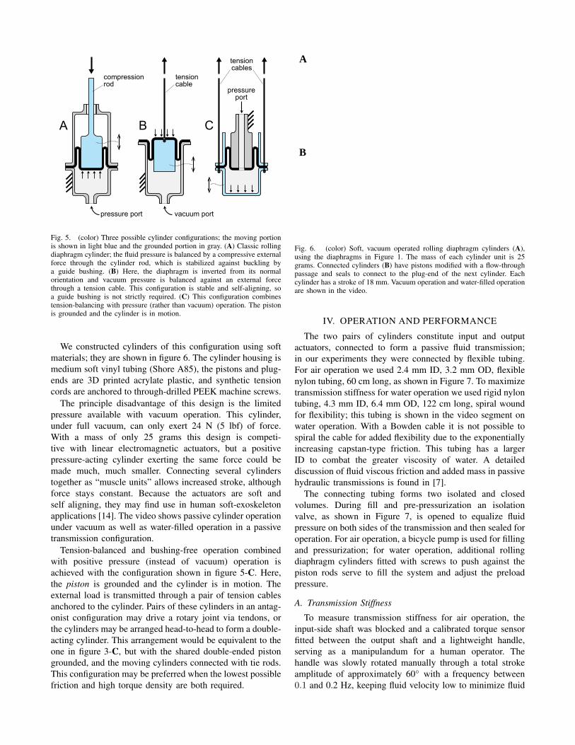
Fig. 5. (color) Three possible cylinder configurations; the moving portionis shown in light blue and the grounded portion in gray. (A) Classic rollingdiaphragm cylinder; the fluid pressure is balanced by a compressive externalforce through the cylinder rod, which is stabilized against buckling bya guide bushing. (B) Here, the diaphragm is inverted from its normalorientation and vacuum pressure is balanced against an external forcethrough a tension cable. This configuration is stable and self-aligning, soa guide bushing is not strictly required. (C) This configuration combinestension-balancing with pressure (rather than vacuum) operation. The pistonis grounded and the cylinder is in motion.
We constructed cylinders of this configuration using softmaterials; they are shown in figure 6. The cylinder housing ismedium soft vinyl tubing (Shore A85), the pistons and plug-ends are 3D printed acrylate plastic, and synthetic tensioncords are anchored to through-drilled PEEK machine screws.
The principle disadvantage of this design is the limitedpressure available with vacuum operation. This cylinder,under full vacuum, can only exert 24 N (5 lbf) of force.With a mass of only 25 grams this design is competi-tive with linear electromagnetic actuators, but a positivepressure-acting cylinder exerting the same force could bemade much, much smaller. Connecting several cylinderstogether as “muscle units” allows increased stroke, althoughforce stays constant. Because the actuators are soft andself aligning, they may find use in human soft-exoskeletonapplications [14]. The video shows passive cylinder operationunder vacuum as well as water-filled operation in a passivetransmission configuration.
Tension-balanced and bushing-free operation combinedwith positive pressure (instead of vacuum) operation isachieved with the configuration shown in figure 5-C. Here,the piston is grounded and the cylinder is in motion. Theexternal load is transmitted through a pair of tension cablesanchored to the cylinder. Pairs of these cylinders in an antag-onist configuration may drive a rotary joint via tendons, orthe cylinders may be arranged head-to-head to form a double-acting cylinder. This arrangement would be equivalent to theone in figure 3-C, but with the shared double-ended pistongrounded, and the moving cylinders connected with tie rods.This configuration may be preferred when the lowest possiblefriction and high torque density are both required.
B
A
Fig. 6. (color) Soft, vacuum operated rolling diaphragm cylinders (A),using the diaphragms in Figure 1. The mass of each cylinder unit is 25grams. Connected cylinders (B) have pistons modified with a flow-throughpassage and seals to connect to the plug-end of the next cylinder. Eachcylinder has a stroke of 18 mm. Vacuum operation and water-filled operationare shown in the video.
IV. OPERATION AND PERFORMANCE
The two pairs of cylinders constitute input and outputactuators, connected to form a passive fluid transmission;in our experiments they were connected by flexible tubing.For air operation we used 2.4 mm ID, 3.2 mm OD, flexiblenylon tubing, 60 cm long, as shown in Figure 7. To maximizetransmission stiffness for water operation we used rigid nylontubing, 4.3 mm ID, 6.4 mm OD, 122 cm long, spiral woundfor flexibility; this tubing is shown in the video segment onwater operation. With a Bowden cable it is not possible tospiral the cable for added flexibility due to the exponentiallyincreasing capstan-type friction. This tubing has a largerID to combat the greater viscosity of water. A detaileddiscussion of fluid viscous friction and added mass in passivehydraulic transmissions is found in [7].
The connecting tubing forms two isolated and closedvolumes. During fill and pre-pressurization an isolationvalve, as shown in Figure 7, is opened to equalize fluidpressure on both sides of the transmission and then sealed foroperation. For air operation, a bicycle pump is used for fillingand pressurization; for water operation, additional rollingdiaphragm cylinders fitted with screws to push against thepiston rods serve to fill the system and adjust the preloadpressure.
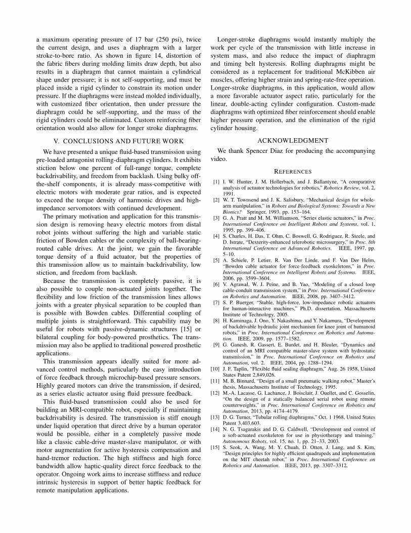
A. Transmission Stiffness
To measure transmission stiffness for air operation, theinput-side shaft was blocked and a calibrated torque sensorfitted between the output shaft and a lightweight handle,serving as a manipulandum for a human operator. Thehandle was slowly rotated manually through a total strokeamplitude of approximately 60◦ with a frequency between0.1 and 0.2 Hz, keeping fluid velocity low to minimize fluid
isolation valve
fill valve
bleed valve
output side input side
brushless motor+ 12:1 friction drive
Fig. 7. (color) Benchtop transmission testing setup, plumbed for airoperation. In addition to the primary isolation valve, each line on theinput side has a local isolation valve to minimize transmission volume andcompliance during operation. During water operation a rolling diaphragmcylinder-based reservoir is used to fill and pressurize the system. Themotor and friction drive gear reduction used for powered tests is somewhatunderpowered for this transmission; to equal the continuous torque ratingof the transmission would require a total gear ratio of 42:1. The bare motor,without encoder or gear reduction, weights 260 grams.
damping. Both the input and output shafts are fitted with10,000 count (after quadrature) optical encoders. Figure 8plots work loops measured at 2 bar and 6 bar. Additionalwork loops were made with the isolation valve open, wheretransmission stiffness should be zero. These loops were fullstroke, pushing until the cylinders bottomed out to measurethe total range of motion. All work loops are clockwise,indicating energy loss, and are smooth, with no coggingevident from the timing belts.
The air tubing internal volume is about 70% of the theo-retical cylinder volume. Because initial stiffness is inverselyproportional to internal air volume, the achievable stiffnessmight be doubled over the result here by using smallerbore tubing and with more careful attention to the internalgeometry of the valves.
Stiffness of the transmission when filled with water is21 N-m/rad, as shown in Figure 9, also measured by man-ually backdriving the blocked transmission, with a torque-sensor-fitted handle.
A Maxon EC32 brushless motor with a 12:1 friction-drive gear reduction was fitted to the input side of thetransmission and used to render a linear spring. This gearratio was selected to maintain backdrivability and be feasibleto make with a single-stage. It provides sufficient torquefor testing but cannot deliver the transmission’s full ratedtorque. Figure 10 shows a work loop when the handle isoperated against the motor on the input-side shaft directlyand then on the output shaft; in both cases the motor rendereda 1 N-m/rad virtual spring. Dissipation in the friction driveis negligible compared to the transmission. Performance is
−40 −30 −20 −10 0 10 20 30 40−1
−0.8
−0.6
−0.4
−0.2
0
0.2
0.4
0.6
0.8
1air3working3fluid
manipulandum3angle3(deg)
torq
ue3(
N−
m)
63bar3(873psi)3air
23bar3(293psi)3air
isolation3valve3open
Fig. 8. (color) Air operation. The input shaft is blocked and a handlewith a torque sensor is manually operated to determine system stiffness.Operation with the isolation valve open demonstrates the lack of significanttransmission spring rate. For pressurized operation, work loops from twoindependent trials are overlain.
−5 −4 −3 −2 −1 0 1 2 3 4 5
−1.5
−1
−0.5
0
0.5
1
1.5
2blockedNstiffness:NwaterNfill
manipulandumNangleN(deg)
torq
ueN(
N−
m)
Fig. 9. (color) Water operation, 2.75 bar (40 psi) preload pressure. Thesetup is the same as for air stiffness tests. System stiffness with wateroperation measures approximately 21 N-m/rad.
very similar to the air operation tests, but in this case bothtransmission shafts are in motion during the work loop and sothe overall hysteresis and friction is higher. In all motorizedtests, encoder feedback comes only from the transmissioninput shaft; neither the output shaft angle or line pressuresare used to improve the rendering. The low stiction andsmooth behavior of the transmission should allow for muchhigher performance with a more sophisticated controller andadditional feedback.
Compliance in the transmission during water operation isa combination of breathing of the tubing, stretching of thediaphragms, and compliance in the timing belts. Separatingout each effect would require careful tests with variation ofthe parameters of each component; the intent here is to illus-trate characteristic performance under realistic conditions.
B. Dynamic Performance
Force bandwidth was measured by commanding sinusoidaltorques to the motor at the input shaft and attaching the

−40 −30 −20 −10 0 10 20 30 40−0.8
−0.6
−0.4
−0.2
0
0.2
0.4
0.6
0.8water8working8fluid
manipulandum8angle8(deg)
torq
ue8(
N−
m)
blocked8input8shaft
motor8output8withouttransmission
rendered8work-loopagainst818N-m/radvirtual8spring
Fig. 10. (color) Water operation, 2.75 bar (40 psi) preload pressure. Resultof haptic rendering of an ideal 1 N-m/rad linear spring (dashed line). Ameasured work loop, hand traversed, at both the motor friction drive outputshaft without the transmission (orange) and with the transmission fitted,measured at the output shaft (blue). Maximum system stiffness is shownfor reference (red).
torque sensor between the output shaft and ground. Thecurrent amplitude was 3 Amps, corresponding to a measuredstatic output torque, after the friction drive, of 0.375 N-m.Results for both air and water are shown in Figure 11. At1 Hz, force transmission efficiency was 82% for water filland 67% for air fill. The second resonance peak during wateroperation may result from fluid acceleration, which acts as asecond effective mass in the system, but detailed modelingand further analysis is required. Extracting this effect wouldalso require separate characterization of the friction drivewithout the fluid transmission.
We also measured displacement step responses to a com-manded 20◦ step input, as shown in Figure 12. For this test,simple PD feedback was applied to the input shaft encoderreading. All tests used the same gain values. In this test, theadded inertia of the water is evident; the motor is torquesaturated for most of the response time so the water-filledstep response is acceleration limited. Note that the water-filled transmission maintains almost exact synchronizationbetween the input and output. Steady-state errors result froma lack of integral feedback. In this test, the manipulandumhandle is mounted to the output shaft, with a measured massmoment of inertia of 9.8×10⁻⁴ kg-m2.
The video shows a high-speed video recording of thetransmission driven by an impulse, and the resulting timeresponse. The video also shows passive operation with a500 gram load attached to the output handle.
C. Friction, Hysteresis, and Backlash
Hysteresis is clearly evident in the work loops shown (andnoticeable when manipulating the transmission by hand). Thework loops testing transmission stiffness at 6 bar air pressureexhibit a total hysteresis torque amplitude of 230 mN-m,or 4% of full-range rated torque (±2.7 N-m). At 2 bar,hysteresis is 170 mN-m (3%). When rendering the linearspring for water-filled operation, where all four diaphragmsare in motion, hysteresis was 330 mN-m (6%) .
10−1
100
101
102
−10
−5
0
5
10
15
frequencyB(Hz)
outp
utBfo
rceB
(dB
)
forceBbandwidth
2.75BbarB(40Bpsi)Bwater
6BbarB(87Bpsi)Bair
Fig. 11. (color) Force bandwidth is measured by fitting a torque sensorto the transmission output which is in turn grounded. Sinusoidal torquesat individual frequencies are commanded to the motor. At DC, water-mode achieves 82% force transfer, air-mode 67%, comparing measuredtransmission output shaft torque to measured friction drive output shafttorque.
0 0.1 0.2 0.3 0.4 0.50
5
10
15
20
25stephresponses
timeh(sec)
angl
eh(d
eg) 6hbarh(87hpsi)hair
2hbarh(29hpsi)hairh(outputhangles)
hh2hbarh(29hpsi)hair(inputhshafthangle)
2.75hbarh(40hpsi)hwater
Fig. 12. (color) For this test, the manipulandum handle was fittedto the transmission output shaft; its measured moment of inertia is9.8×10−4 kg-m2.
Stiction, which appears in the work loop plots as a verticaldrop in torque with no change in angle, is low in all tests.Work loops collected during air operation show a stiction of20 to 35 mN-m. For water operation during haptic rendering,stiction was 30 to 50 mN-m. Overall, maximum stiction wasobserved to be less than 1% of full-range torque.
Hysteresis is caused by the rolling and unrolling of thediaphragm and, to a lesser extent, flexing of the timingbelt. Improving hysteresis directly will likely require theuse of a diaphragm elastomer with an intrinsically lowermechanical loss tangent and higher resilience, or thinner di-aphragms. Because the observed hysteresis was very smoothand repeatable, we are confident that additional feedback andcontrol will reduce its impact. Future work should includeservo-driven (dynamometer) work loop testing to accuratelydetermine the effect of velocity on hysteresis.
Figure 13 shows transmission operation, water-filled to2.75 bar (40 psi), manually driven over most of the transmis-

0 2 4 6 8 10 12 14 16 18−30
−20
−10
0
10
20
30
shaf
t.ang
le.(
deg)
backlash.test:.water.working.fluid
time.(sec)
0 2 4 6 8 10 12 14 16 18−0.6
−0.4
−0.2
0
0.2
0.4
0.6
time(sec)
θin
put−θ
outp
ut(d
eg)
output.shaft.angle
input.shaft.angle
Fig. 13. (color) Water operation, 2.75 bar (40 psi). The input was manipulated manually over various ranges and speeds to determine tracking errors andbacklash.
sion stroke. Synchronization between the input and outputshaft is maintained to less than 0.5 degrees. Note that thetracking error is in phase with the input angle. This, andthe smooth error signal, indicate that transmission backlash,vis-a-vis lost motion, is effectively zero, and the trackingerror results only from the small, but non-zero, transmissioncompliance.
D. Limitations, Variations, and Improvements
This constant-volume transmission technique is attractivebecause of its simplicity and passivity. However, long-termoperation relies upon continued maintenance of a constantvolume state. The choice of materials is then especially im-portant to minimize absorption of liquid and/or permeabilityof air. Thicker diaphragms are more impermeable, but willsuffer greater hysteresis. Because the transmission is underconstant pressure, even at rest, material creep, particularlyin the tubing or hose, can lead to volume change. If manytransmissions are used in a complex system, it should still berelatively straightforward to periodically open the isolationvalves and reset the pressure as needed. The impact of creepand absorption and the difficulty of mitigating their effectswill become clearer with increasing use of this transmissionmethod.
Ultimately, use of this transmission in motor-driven sys-tems is only beneficial if the output actuator has a highertorque density than the motor it displaces. Overall torquedensity is limited by the input motor, so using this transmis-sion will actually decrease overall torque density, but limbinertia will be significantly reduced. This first-generationtransmission design, using off-the-shelf components, is heavyand not optimized for high torque density. When filled with
Fig. 14. Commercially available rolling diaphragms are produced bycompression molding thin sheets of rubber backed by a finely woven high-tenacity fabric. Even with a high-drape weave, the diaphragm may only bedrawn so far before fabric distortion becomes excessive and pleating occurs.This illustration shows the typical deformation patterns of the fibers aftermolding.
water, the output actuator weighs 246 grams. As a point ofreference, the EC32 2-pole brushless motor used in testingthe transmission weighs 260 grams, and requires a 42:1 gearratio to equal the torque rating of the transmission rotaryactuator, so this transmission already exceeds the torquedensity of lightly geared motors. For further comparison,a Dynamixel MX-28 servo can produce up to 3.1 N-m oftorque and weights only 72 grams, but with a transmissionratio of 193:1, it is restricted to slow speeds and exhibitsvery high output impedance.
With future refinement, we believe the torque density ofthis transmission can be improved by an order of magnitude.Optimization of the cylinders and actuator structure canreduce mass, perhaps by a factor of three. The secondgeneration transmission, currently under development, has
a maximum operating pressure of 17 bar (250 psi), twicethe current design, and uses a diaphragm with a largerstroke-to-bore ratio. As shown in figure 14, distortion ofthe fabric fibers during molding limits draw depth, but alsoresults in a diaphragm that cannot maintain a cylindricalshape under pressure; it is not self-supporting, and must beplaced inside a rigid cylinder to constrain its motion underpressure. If the diaphragms were instead molded individually,with customized fiber orientation, then under pressure thediaphragm could be self-supporting, and the mass of therigid cylinders could be eliminated. Custom reinforcing fiberorientation would also allow for longer stroke diaphragms.
V. CONCLUSIONS AND FUTURE WORK
We have presented a unique fluid-based transmission usingpre-loaded antagonist rolling-diaphragm cylinders. It exhibitsstiction below one percent of full-range torque, completebackdrivability, and freedom from backlash. Using bulky off-the-shelf components, it is already mass-competitive withelectric motors with moderate gear ratios, and is expectedto exceed the torque density of harmonic drives and high-impedance servomotors with continued development.
The primary motivation and application for this transmis-sion design is removing heavy electric motors from distalrobot joints without suffering the high and variable staticfriction of Bowden cables or the complexity of ball-bearing-routed cable drives. At the joint, we gain the favorabletorque density of a fluid actuator, but the properties ofthis transmission allow us to maintain backdrivability, lowstiction, and freedom from backlash.
Because the transmission is completely passive, it isalso possible to couple non-actuated joints together. Theflexibility and low friction of the transmission lines allowsjoints with a greater physical separation to be coupled thanis possible with Bowden cables. Differential coupling ofmultiple joints is straightforward. This capability may beuseful for robots with passive-dynamic structures [15] orbilateral coupling for body-powered prosthetics. The trans-mission may also be applied to traditional powered prostheticapplications.
This transmission appears ideally suited for more ad-vanced control methods, particularly the easy introductionof force feedback through microchip-based pressure sensors.Highly geared motors can drive the transmission, if desired,as a series elastic actuator using fluid pressure feedback.
This fluid-based transmission could also be used forbuilding an MRI-compatible robot, especially if maintainingbackdrivability is desired. The transmission is stiff enoughunder liquid operation that direct drive by a human operatorwould be possible, either in a completely passive modelike a classic cable-drive master-slave manipulator, or withmotor augmentation for active hysteresis compensation andhand-tremor reduction. The high stiffness and high forcebandwidth allow haptic-quality direct force feedback to theoperator. Ongoing work aims to increase stiffness and reduceintrinsic hysteresis in support of better haptic feedback forremote manipulation applications.
Longer-stroke diaphragms would instantly multiply thework per cycle of the transmission with little increase insystem mass, and also reduce the impact of diaphragmand timing belt hysteresis. Rolling diaphragms might beconsidered as a replacement for traditional McKibben airmuscles, offering higher strain and spring-rate-free operation.Longer-stroke diaphragms, in this application, would allowa more favorable actuator aspect ratio, particularly for thelinear, double-acting cylinder configuration. Custom-madediaphragms with optimized fiber reinforcement should enablehigher pressure operation, and the elimination of the rigidcylinder housing.
ACKNOWLEDGMENT
We thank Spencer Diaz for producing the accompanyingvideo.
REFERENCES
[1] I. W. Hunter, J. M. Hollerbach, and J. Ballantyne, “A comparativeanalysis of actuator technologies for robotics,” Robotics Review, vol. 2,1991.
[2] W. T. Townsend and J. K. Salisbury, “Mechanical design for whole-arm manipulation,” in Robots and Biological Systems: Towards a NewBionics? Springer, 1993, pp. 153–164.
[3] G. A. Pratt and M. M. Williamson, “Series elastic actuators,” in Proc.International Conference on Intelligent Robots and Systems, vol. 1,1995, pp. 399–406.
[4] S. Charles, H. Das, T. Ohm, C. Boswell, G. Rodriguez, R. Steele, andD. Istrate, “Dexterity-enhanced telerobotic microsurgery,” in Proc. 8thInternational Conference on Advanced Robotics. IEEE, 1997, pp.5–10.
[5] A. Schiele, P. Letier, R. Van Der Linde, and F. Van Der Helm,“Bowden cable actuator for force-feedback exoskeletons,” in Proc.International Conference on Intelligent Robots and Systems. IEEE,2006, pp. 3599–3604.
[6] V. Agrawal, W. J. Peine, and B. Yao, “Modeling of a closed loopcable-conduit transmission system,” in Proc. International Conferenceon Robotics and Automation. IEEE, 2008, pp. 3407–3412.
[7] S. P. Buerger, “Stable, high-force, low-impedance robotic actuatorsfor human-interactive machines,” Ph.D. dissertation, MassachusettsInstitute of Technology, 2005.
[8] H. Kaminaga, J. Ono, Y. Nakashima, and Y. Nakamura, “Developmentof backdrivable hydraulic joint mechanism for knee joint of humanoidrobots,” in Proc. International Conference on Robotics and Automa-tion. IEEE, 2009, pp. 1577–1582.
[9] G. Ganesh, R. Gassert, E. Burdet, and H. Bleuler, “Dynamics andcontrol of an MRI compatible master-slave system with hydrostatictransmission,” in Proc. International Conference on Robotics andAutomation, vol. 2. IEEE, 2004, pp. 1288–1294.
[10] J. F. Taplin, “Flexible fluid sealing diaphragm,” Aug. 26 1958, UnitedStates Patent 2,849,026.
[11] M. B. Binnard, “Design of a small pneumatic walking robot,” Master’sthesis, Massachusetts Institute of Technology, 1995.
[12] M.-A. Lacasse, G. Lachance, J. Boisclair, J. Ouellet, and C. Gosselin,“On the design of a statically balanced serial robot using remotecounterweights,” in Proc. International Conference on Robotics andAutomation, 2013, pp. 4174–4179.
[13] D. G. Turner, “Tubular rolling diaphragms,” Oct. 1 1968, United StatesPatent 3,403,603.
[14] N. G. Tsagarakis and D. G. Caldwell, “Development and control ofa soft-actuated exoskeleton for use in physiotherapy and training,”Autonomous Robots, vol. 15, no. 1, pp. 21–33, 2003.
[15] S. Seok, A. Wang, M. Y. Chuah, D. Otten, J. Lang, and S. Kim,“Design principles for highly efficient quadrupeds and implementationon the MIT cheetah robot,” in Proc. International Conference onRobotics and Automation. IEEE, 2013, pp. 3307–3312.