a- maca n v technical nasa tm x-1345 -1 memorandum
TRANSCRIPT

*u)LL- ,
a- M A C A n v - 1 T E C H N I C A L N A S A TM X-1345 M E M O R A N D U M
L n d m
x w
I
=E c 4 c/) 4 z
N A T I O N A L A E R O N A U T I C S A N D SPACE A D M I N I S T R A T I O N W A S H I N G T O N , D . C. F E B R U A R Y 1 9 6 7

I
NASA TM X-1345
STATIC AERODYNAMIC CHARACTERISTICS OF A MODEL OF A
TYPICAL SUBSONIC JET-TRANSPORT AIRPLANE AT
MACH NUMBERS FROM 0.40 TO 1.20
By Eugene N. Brooks, Jr., John P. Decker, and James A. Blackwell, Jr.
Langley Research Center Langley Station, Hampton, Va.
NATIONAL AERONAUTICS AND SPACE ADMINISTRATION
For sale by the Clearinghouse for Federal Scientific and Technical Information Springfield, Virginia 22151 - Price $2.00

STATIC AERODYNAMIC CHARACTERISTICS OF A MODEL OF A
TYPICAL SUBSONIC JET-TRANSPORT AIRPLANE AT
MACH NUMBERS FROM 0.40 TO 1.20
By Eugene N. Brooks, Jr., John P. Decker, and James A. Blackwell, Jr.
Langley Research Center
SUMMARY
An investigation was conducted in the Langley 8-foot transonic pressure tunnel to determine the static aerodynamic characteristics of a model of a typical subsonic, swept- wing, jet-transport airplane at large angles of attack and transonic Mach numbers. The Mach number range extended from 0.40 to 1.20 and the angle-of-attack range from -8' to 18O.
The resul ts indicate that the model was longitudinally stable at zero sideslip angle for lift coefficients between 0.15 to 0.50 corresponding to angles of attack up to about 3' throughout the Mach number range. In the same lift-coefficient range and at Mach numbers above 0.90, the model exhibited large increases in static margin with small changes in Mach number. At lift coefficients between 0.50 and 0.80, the static margin decreased to approximately zero for Mach numbers between 0.40 and 0.80. At iift coefficients greater than 0.80, corresponding to angles of attack greater than 7O, the model was longitudinally stable at all Mach numbers except between 0.95 and 1.03.
For small sideslip angles and at Mach numbers below 0.90, the model had positive effective dihedral; however, the model had negative effective dihedral for Mach numbers of 0.90 and 0.95 over significant portions of the lift-coefficient range. At a Mach number of 0.90, the model was longitudinally unstable for a sideslip angle of 5' in about the same lift-coefficient range in which the effective dihedral was negative. Weathercock stability was maintained for all Mach numbers and angles of attack.
INTRODUCTION
The National Aeronautics and Space Administration is studying the aerodynamic characteristics and handling qualities of large swept-wing, subsonic, jet-transport air- craft to aid in determining the piloting procedures necessary to recover from high angle- of -attack and transonic Mach number conditions sometimes encountered in very turbulent

air. It is known that transport airplanes similar to the configuration of this study have encountered turbulent conditions in flight and have dived rapidly and reached Mach numbers as high as 1.08. Theoretical predictions of the static and dynamic aerodynamic characteristics of subsonic jet-transport-airplane configurations a r e available , but these predictions are not considered applicable at high angles of attack and transonic Mach numbers. To provide accurate dynamic data at the angles of attack and Mach numbers of interest in this study, the dynamic characteristics of a model of a typical subsonic jet-transport airplane have been investigated and reported in reference 1.
As a continuation of the dynamic stability study and as part of the overall program, the purpose of the present investigation is to provide the static aerodynamic stability data for the model of reference 1. Tests were conducted in the Langley 8-foot transonic pressure tunnel over a Mach number range of 0.40 to 1.20, an angle-of-attack range from about -8Oto 18O, and generally at angles of sideslip of Oo, 2O, and 5'.
SYMBOLS
The results a r e presented as force and moment coefficients with the longitudinal aerodynamic parameters referred to the stability system of axes and the lateral aero- dynamic parameters referred to the body system of axes. The origin for these axes systems is the moment reference center of the model which is located at the quarter chord of the mean aerodynamic chord of the wing. (See fig. 1.) Measurements a r e given in the International System of Units (SI) and parenthetically in the U.S. Customary Units. Conversion factors for these units a r e given in reference 2. The symbols a r e defined as follows:
I
b wing span, 0.997 meter (3.271 ft)
C mean aerodynamic chord of wing, 0.154 meter (0.504 ft)
M free-stream Mach number
q free-stream dynamic pressure, newtons/meter2 (lbf/ft2)
R Reynolds number based on 7Z
r radius
S reference wing area, 0.148 meter2 (1.597 ft2)
-
2

angle of attack referred to body reference axis, deg
angle of sideslip, deg
Lift q s
lift coefficient, - pitching-moment coefficient, Pitching moment
- G'i5
Rolling moment rolling-moment coefficient, qSb
Yawing moment yawing-moment coefficient, - qSb
Side force side-force coefficient,
lift-curve slope - measured from CL = 0.15 to CL = 0.50
measured from CL = 0.15 to CL = 0.50 aCm static margin - aCL
q s aCL aa
effective dihedral parameter, - "1 Ap = 2 O AP '
directional-stability parameter, - Ap=.2' AP '
side-force parameter, - A P z 2 O AP
DESCRIPTION O F THE MODEL
The physical characteristics and dimensions of the test model, which are consid- ered representative of current subsonic jet-transport-airplane configurations, a r e pre- sented in figure 1. Photographs showing two views of the model a r e shown in figure 2. Table I presents several geometric properties of the wing, horizontal tail, and vertical tail and table I1 presents airfoil coordinates for the same components.
The model had a low swept wing with four jet-engine nacelles mounted beneath the wing on slab pylons. The portion of the wing inboard of the innermost pylons had a leading-edge sweepback angle of 41.5' and outboard of these inner pylons, a leading-edge sweepback angle of 37.5'. The horizontal tail was set at an incidence angle of 0'. In order to retain the actual fuselage afterbody closure, the sting was designed to enter the model at the bottom of the fuselage at an angle of 6' with respect to the body reference axis. The model geometry and configuration were fixed throughout the test , and there were no movable control surfaces.
3

TESTS, APPARATUS, AND CORRECTIONS
The investigation was conducted in the Langley 8-foot transonic pressure tunnel, which is a rectangular, single-return wind tunnel with slotted test section. Tests were conducted for a Mach number range from 0.40 to 1.20, an angle-of-attack range from about -8' t o la0, and generally at angles of sideslip of approximately Oo, 2O, and 5'. The variation of the test Reynolds number, based on the mean aerodynamic chord, with Mach number is as shown in figure 3 unless noted otherwise.
Tests were conducted with boundary-layer transition fixed with 0.25-centimeter- wide (0.10-in.-wide) s t r ips of No. 80 carborundum grains set in a plastic adhesive. The three-dimensional roughness was applied with the forward edges of the s t r ips positioned (1) 0.76 cm (0.30 in.) behind the leading edge of the wing and engine nacelles (2) 0.864 cm (0.34 in.) rearward from the tip of the nose (3) 0.508 cm (0.20 in.) rearward from the leading edge of the horizontal tail and (4) 0.66 cm (0.26 in.) rearward from the leading edge of the vertical tail, (All distances were measured in the streamwise direction.)
Force and moment measurements were made with a six-component internally mounted strain-gage balance. The angles of attack and sideslip were corrected for deflection of the balance and sting under aerodynamic loads and for tunnel flow angu- larity. Corrections were not made for sting interference effects caused by the sting entering the fuselage from beneath the model rather than from the rear of the model. The sting interference could affect the longitudinal and the lateral-directional aerody- namic characteristics. The accuracy of the data based upon repeatability and static calibrations is as follows:
CL . . . . . . . . . . . . . . . . . . . . . . . . . . . . . . . . . . . . . . . . . *0.01
Cm . . . . . . . . . . . . . . . . . . . . . . . . . . . . . . . . . . . . . . . . . f0.005
Cz . . . . . . . . . . . . . . . . . . . . . . . . . . . . . . . . . . . . . . . . . f0.0005
Cn . . . . . . . . . . . . . . . . . . . . . . . . . . . . . . . . . . . . . . . . . f0.0005
cy . . . . . . . . . . . . . . . . . . . . . . . . . . . . . . . . . . . . . . . . . *0.005
a, degree . . . . . . . . . . . . . . . . . . . . . . . . . . . . . . . . . . . . . *0.1
°ree . . . . . . . . . . . . . . . . . . . . . . . . . . . . . . . . . . . . . f O . l
M . . . . . . . . . . . . . . . . . . . . . . . . . . . . . . . . . . . . . . . . . f0.003
4

PRESENTATION OF RESULTS
~
~
Variation of lateral-stability derivatives with I lift coefficient . . . . . . . . . . . . . . . . . . . . . . . . . . . . . . . . . . . . 8
Machnumber . . . . . . . . . . . . . . . . . . . . . . . . . . . . . . . . . . . . 9 Variation of lateral- stability derivatives with
The results of this investigation have been reduced to coefficient and parameter form. The basic longitudinal aerodynamic data are presexted in figure 4 and summa- rized in figure 5. The basic lateral aerodynamic data are presented in figures 6 and 7 and summarized in figures 8 and 9. To aid in the location of data, the following list is given:
Figure 4 Aerodynamic characteristics in pitch . . . . . . . . . . . . . . . . . . . . . . . . .
Variation of lift-curve slope and static longitudinal-
Variation of lateral-stability characteristics
Variation of pitching-moment and lateral-stability
stability parameter with Mach number . . . . . . . . . . . . . . . . . . . . . . . 5
with sideslip angle . . . . . . . . . . . . . . . . . . . . . . . . . . . . . . . . . 6
characteristics with lift coefficient . . . . . . . . . . . . . . . . . . . . . . . . . 7
I DISCUSSION
Longitudinal Aerodynamic Char act erist ics
Figure 4 shows the curves for the variation of angle of attack with lift coefficient to be essentially linear between CL = 0.15 and CL = 0.50 throughout the Mach number range. At lift coefficients above about 0.50 and at Mach numbers up to 0.925, the curves became nonlinear and the lift-curve slopes decreased to less than one-half the values measured in the CL range from 0.15 to 0.50. At Mach numbers above 0.925, similar results a r e shown; however, decreases in lift-curve slope were delayed to lift coefficients of approximately 0.80. The lift-curve slope, as measured between CL = 0.15 and 0.50, is shown in figure 5 to have increased with Mach number up to 0.80. At Mach numbers above 0.80, C L ~ decreases, and a lift-curve slope "bucket" is shown at a Mach number of 0.925; this condition is typical of high-aspect-ratio thick wings.
In figure 4 the pitching-moment curves are shown to be essentially linear and the model remains stable between CL = 0.15 and 0.50 for all Mach numbers. At lift coefficients between 0.50 and 0.80 (that is, between c y = 3 O and 7O), the static margin decreased to approximately zero for Mach numbers between 0.40 and 0.80. At lift coefficients greater than 0.80 (that is, a above approximately 7O), the model was
5

longitudinally stable at all Mach numbers except at Mach numbers between 0.95 and 1+.03 where some longitudinal instability is indicated. At the Mach numbers at which negative lift coefficients were investigated, the model is longitudinally stable except at M = 0.95 where longitudinal instability is indicated in the CL range from -0.25 to -0.05.
The static margin CmcL (fig.5) remains practically invariant for Mach numbers f rom 0.40 to 0.90. At Mach numbers above 0.90, large increases in static margin with small changes in Mach number a r e indicated. These increases in static margin amount to a rearward shift in the aerodynamic center of 0.34F with only a 0.15 increase in Mach number.
Lateral Aerodynamic Characteristics
Figure 6 shows the rolling-moment coefficient Cl , yawing-moment coefficient Cn, and side-force coefficient C y to be essentially linear between p = i2'. Both the effective dihedral and the weathercock stability decreased at large sideslip angles (that is, above approximately 7') at all Mach numbers and angles of attack except at M = 0.90 and CY= 3.20°, where the effective dihedral was negative +Cl at small sideslip angles but positive (-Cl p) at large sideslip angles; and at M = 0.95 and CY = 3.15', where the positive effective dihedral increased with increasing sideslip angle.
Since Ci , Cn, and C y were only linear between = *2O for all Mach numbers, the lateral-directional stability parameters shown in figures 8 and 9 were computed by using the data of figure 7 and taking finite differences in the coefficients between p = 0' and 2'.
( 13)
Figure 8 shows that at the lower Mach numbers the model had positive effective throughout the lift-coefficient range. However, at M = 0.90 and 0.95, dihedral (-C
the model had negative effective dihedral +C at the lower l i f t coefficients. Fig- ure 7(d) shows that at approximately the s me lift coefficients that negative effective dihedral was exhibited at M = 0.90, pitch nonlinearities existed for
4 d /3 = 5.09'.
Figures 8 and 9 show that the weathercock stability was maintained and that the directional stability derivative Cnp varied between 0.0016 and 0.0039 throughout the Mach number and lift-coefficient ranges. The side-force parameter Cyp is seen in figures 8 and 9 to be practically invariant with Mach number and lift coefficient and deviates very little from a value of -0.02.
SUMNIARY OF RESULTS
Results of an aerodynamic investigation of a model of a typical swept-wing subsonic jet-transport airplane conducted over an angle-of-attack range from about -8' to 18O, at
6

a a c h numbers from 0.40 to to 1.20, and generally at angles of sideslip of Oo, 2 O , and 5O, indicate the following:
1. Between lift coefficients of 0.15 and 0.50 the lift curves were essentially linear for all Mach numbers, but for lift coefficients above 0.50 and at Mach numbers up to 0.925 the lift curves became nonlinear and the lift-curve slopes decreased to less than one-half the value measured between lift coefficients of 0.15 and 0.50.
2. At zero sideslip angle the model was longitudinally stable over a lift-coefficient range from 0.15 to 0.50 for all Mach numbers. The static margin for this lift range remained practically invariant up to a Mach number of 0.90. At Mach numbers above 0.90 the model exhibited large increases in static margin with small changes in Mach number. At lift coefficients between 0.50 and 0.80 the static margin decreased to approximately zero for Mach numbers between 0.40 and 0.80. Longitudinal instabilities a r e indicated for lift coefficients above 0.80 at Mach numbers between 0.95 and 1.03 and for negative lift coefficients at a Mach number of 0.95.
3. At Mach numbers below 0.90 the model had positive effective dihedral for small sideslip angles. However, at Mach numbers of 0.90 and 0.95 negative effective dihedral was exhibited over significant portions of the lift-coefficient range, At a Mach number of 0.90 the model also developed pitch nonlinearities at a sideslip angle of approximately 5O in about the same lift-coefficient range in which the effective dihedral was negative.
4. For small sideslip angles weathercock stability was maintained throughout the Mach number and angle-of-attack ranges of this investigation.
Langley Research Center, National Aeronautics and Space Administration,
Langley Station, Hampton, Va., October .26, 1966, 126-13-01-31-23.
REFERENCES
1. Wright, Bruce R.; and Brower, Margaret L: Aerodynamic Damping and Oscillatory Stability in Pitch for a Model of a Typical Subsonic Jet-Transport Airplane. NASA TN D-3159, 1966.
2. Mechtly, E. A.: The International System of Units - Physical Constants and Con- version Factors. NASA SP-7012, 1964.
7

TABLE 1.- GEOMETRIC PROPERTIES OF WING.
HORIZONTAL TAIL. AND VERTICAL TAIL
Wing: Area.
2 meters . . . . . . . f t 2 . . . . . . . . .
Span 1
meters . . . . . . . f t . . . . . . . . .
Mean aerodynamic chord. meters . . . . . . . f t . . . . . . . . .
Aspect r a t i o . . . . . Taper r a t i o . . . . . . Geometric d i h e d r a l . deg
Hor izonta l t a i l : Area.
meter s 2 . . . . . . . f t 2 . . . . . . . . .
Span 9
meter s . . . . . . . f t . . . . . . . . .
Mean aerodynamic chord. meters . . . . . . . f t . . . . . . . . . meters . . . . . . . f t . . . . . . . . .
Aspect r a t i o . . . . . Taper r a t i o . . . . . . Geometric d i h e d r a l . deg
Root chord.
. . . . . . . . . . . . . . . . . . .
. . . . . . . . . . . . . . . . . . .
. . . . . . . . . . . . . . . . . . .
. . . . . . . . . . . . . . . . . . .
. . . . . . . . . . . . . . . . . . .
. . . . . . . . . . . . . . . . . . .
. . . . . . . . . . . . . . . . . . .
. . . . . . . . . . . . . . . . . . .
. . . . . . . . . . . . . . . . . . . .
. . . . . . . . . . . . . . . . . . .
. . . . . . . . . . . . . . . . . . .
. . . . . . . . . . . . . . . . . . .
. . . . . . . . . . . . . . . . . . .
. . . . . . . . . . . . . . . . . . .
. . . . . . . . . . . . . . . . . . .
. . . . . . . . . . . . . . . . . . .
. . . . . . . . . . . . . . . . . . .
. . . . . . . . . . . . . . . . . . .
. . . . . . . . . . . . . . . . . . .
. . . . . . . . . . . . . . . . . . .
V e r t i c a l t a i l : Area.
2 meters . . . . . . . . . . . . . . . . . . . . . . . . . . f t 2 . . . . . . . . . . . . . . . . . . . . . . . . . . . .
Mean aerodynamic chord, meters . . . . . . . . . . . . . . . . . . . . . . . . . . f t . . . . . . . . . . . . . . . . . . . . . . . . . . . .
Aspect r a t i o . . . . . . . . . . . . . . . . . . . . . . . . Taper r a t i o . . . . . . . . . . . . . . . . . . . . . . . . .
0.1413 1.5209
0.9970 3.2710
0.1536 0.5039
7.035 0.33
7
0.0321 0.3455
0.3304 1.0840
0.1015 0.3330
0.1359 0.4459
3.43 0 . 4 1
7
0.0196 0.2110
0.1125 0.3691
1 . 8 0 0 .31
a

Ordinate
0.0297 .0152 .0132 .0096 .0017
-.0066 -.0132 -.0198 -.0303 -.0376 -.Ob29 -.O462 -.Oh56 -.0383 -.0311 -.0231 -.0152 -.0080 0
Stat ior
0 .0050 .0074 .0126 .0250 .0500 .0750 .lo00 .1500 .ZOO0 .2500 .3000 .4000 .5000 .&IO0 1.0003
Span s ta t ion:
Chord length: 0.0403 meter (0.1323 f t )
0.2747 meter (0.9012 f t )
Span s ta t ion:
Chord length: 0.0953 meter (0.3125 f t )
0.1993 meter (0.6538 f t )
TABLE E.- AIRFOIL COORDINATES
[Stations and ordinates have been nondimensionalized with respect to airfoil chora
(a) Wing
Upper surface Upper surface II Lower surface Upper surface Lower surface Lower surface
II Sta t ion Stat ion Ordinate Ordinate Stat ion
0 -0050. .0083 ,0125 .0249 .0500 .0748 .loo0 .1500 .zoo0 .2500 .3000 .4000 .5000 . booo .7000 1.0000
l rd ina te
0 .OU9
.0206
.0256
.0330
.0396
.0446 -0545 .0578 .0628 .0661 .0661 .0611 .0512 .0413
.0165
0
Stat ior
0 , 0 0 5 ~ .0083 .0125 .0219 . 0 500 .0748 .1000 .1500 .2000 .2500 .3000 .4000 .5000 .6000 .7000 1.0000
3rdinate
0 -.0066 -.0074 - .0083 -.0091 -. 0099
-.0132 -.0165 -.0215 -.0248 -.0297 -.0297
- .0264 -. 0198 0
-.0124
- -0289
0 .0050 .0075 .0125 .0250 .0499 .0750 .loo0 .1500 .zoo0 .2500 .2075 .4000 .5000 .a00 .7000 .8000 .89% 1.0000
0.0297 .0442 .0462 .0502 .0588 .0667 .0719 .0743 .0756 .0743 .0719 .0680 .0595 .0502
.0330
.0251
.OU5
.0416
0
0 . 00 50 .0075 .0125 .0250 - 0499 .0750 .loo0 .1500 .2000 .2500 .2075 .A000 .5000 . booo .7000 .8000 -8999 1.0000
0.0236 -0357 .0382
.0523
.0631
.0676
.0727
.0778
.0803
.0790
.0784
.0752
.0726
.0561
.0421
0
Span s ta t ion:
Chord length: 0.2000 meter (0.6562 f t )
0.1537 meter (0.5042 f t )
Upper surface II Lower surface Lower surface Upper surface I 1
Stat ion Ordinate Station I/ Ordinate Station l rdinate Stat ion
0 .0050 .0074 .0126 .0250 .0500 .0753 .loo0 .1500 .2000 .2500 .3000 .LO00 .5000 .6000 .7000 .8000 .9000 1. 0000
Ordinate
0.0030 .0099 .0120 .0147 .0215 .0303 .0385 . o u 2 .0520 .0570 .ob04 .0627 .0644 .0618 -0541 .0427, .0290 -0145
0
0.0032 .0100 .0121 .0161 . 0 2 u .03U .0386 -0443 .0521 .0571 .OM4 .0629 .0646 .0618 .0543 .0429 .0289 .0161
0
0 .0050 .0075 .0125 .0250 .0500 .0750 .loo0 .1500 . a00 .2500 .3000 .4000
' .LO71 .boo0 .7000 .8000 .9000
1.0000
0 - .0046 -.0057 - .0064 -.0075 - .0089 -.0104 -.0118 -.OU6 -.0179 - .0204 - . o m -.0254 -.0250 - .0207 -.0157
-.0054 0
- .0104
3 .0050 .0074 .0126 .0250 .0500 .0753 .loo0 .1500 .zoo0 .2500 .3000 . 4000 .5000 . booo .7000 .8000 .9000
1.0000
0 - .0046 -.0055 -.0065 - .0074 -.0090 -.0105 -.0118 -e0119 -.0177 -.0206 -.0227 -.0253 -.0250 -.0208 -.0156 -.0105 -.0051 0
0 .0050 .0075 .0125 .0250 .0500 .0750 .loo0 .1500 .zoo0 .2500 .3000 .LO00 .4071 . 6000 .7000 .8000 .9000 1.0000
Span s ta t ion:
Chord length: 0.2688 meter (0.8819 f t )
0.1333 meter .(0.4372 f t )
Span s ta t ion:
Chord length: 0.4953 meter (1.6250 f t )
0.0711 meter (0.2333 f t )
9

TABLE E.- AIRFOIL COORDINATES - Concluded
Fations and ordinates have been nondimensionalized with respect to airfoil chord
(b) Horizontal tail
L w e r surface Upper surfare n L w e r surface 1 1 Upper surra-'? Upper sur face Lower su r face - S t a t i o n
~
l rdinatc
- h i i n a t e __ 0.0127
. n a 6
.075~ ,0232 . o m ,9323 ,0332 ,0355 ,0377 .0395 .wi8 .0/+36 . u 4 5 .O4L 5 ,0411, .O?? i . ,0727 . n i l / +
.O723
I1
__ I F l i n a t t l rdinate
__ 0.0142
,0250 .0267 .0281 ,0317 .0347 ,0364 ,0377 . o m ,0457 . OL2F
.OL%
.0498 ,0512 ,0504 ,0442 .033R ,0226 ,0114
0 -
j t s t i o n Irdinata S t a t i m %at ion i t a t i o n __ 1 ,0053 ,0065 ,0175 .075O ,0500 .075n . 1000 ,151'1 . 2noc ,250'1
.4030 . 5900
.7oon
. v n n
.moo
,3000 .350@
,6100
. PO00
S t a t i o n
.0075
.0175
,0500 .0750 .loo0
.20nn ,7500
. Lono
.boon
I .or150 .on75
,0500 .075n . lono . l i o n .20no
,300~1 ,3500 ,4000 ,5030 . honn .7000 .mnn . ?non
i . oonn
.0175
.0250
,7500
0.0131 .020/* .074P ,0268 ,0795 ,0319 .0337 .I34P .n373 .039', .0417 .n437 a 4 5 9 .0472 .0/,6h .0/.?4 ,0337 .72?/, . n i i x 0
n . n m i ,0375 ,0124 ,0251 .Ob99 ,0750 ,130c)
.7101 ,250" .7199 .3500 .410n
. f 300
.7>01 ,799'1 .wnn
i . o m
. i m n
.5 J00
o . n i y ,0221 ,0736 ,0254 ,0774 ,030 'i ,0323 .0333 .0353 .017t ,0396 ,0417 ,0437 .O4h7
.'1/+l/&
. n j x
.n22h
.I7117
,0447
n
n .on51
0.0174 .on20
-.no75 ,0001
-.0051 -.Ill15 - . O M 5 -.,I226 -.0295 -.0348 -.O?R9 -.7417 - . n u 7 -.0U7 - .ou7
-.rl1,1/, -.033R -.n22h -.mi? 0
n .no50 ,0075 . o w .0250 ,0500 ,0750 . lono .150C .70m .250n .3nw
.4non
.5nn0
. honn
.7nnn . xoon . qnnn 1. mn
.350O
0.0177
n -.on23 -.005n
.OOIFI
-.0136 -.OM6 -.72?7 -.0715 -.?350
- . O i l 9 -.03?6
-. 01,3(, - . x,/. 5 - . 0 4 ~ 5 -. w,i/, - .n3 i f , -.n?77 - .n i i i+ 0
,0076 . n i % .O~LY . o m ,0749 . ion1 ,1501 ,1999 ,2499
, 3 5 0 0 ,4001 ,5091
,5999 ,7000 .Ron1 .9nn:,
.3000
1. nno
-.0151 .0409 -.n207 .0750 - . o m .inno - . n 3 3 ~ ,1500
-.OLAL ,2500 -.0399 ,2091
S p ~ n s t a t i o n :
Chnr: I rn- th: 0.0771, metcr (0.23'?1 f t )
C.101 ' i meter (0.32'31 f t )
Span s t a t i o n :
Chnrl lenqlh: 0.0/+34 metrr (0.1473 ? t )
0.1145 rncter (3.1757 f t )
Span s t a t i o n :
Chord lenqth: 0 meter ( n f t )
0.1359 meter ( n . ~ 4 5 q C t )
(c) Vertical tail
I r d i n a t c S t a t i o , I - Sta t ion
0 .0349 ,0175 .Ol26 .0250
.0750
.1501
.2500
.n993
.7mo
.3nnn
.?499
. m i ,5000 ,5999 .7000 .8ono .m3a 1. moo
0 . qnm .no82 .0in5 . ol47 ,0197 .073F ,0274 .7329 .0375 .n4c17 .0430 .0444 .OUR . 0444 .n407 . o m . n m . noic .0147
,0147 .0751 .̂ 196 ,0498 . o m ,0750 .n775 .imi .033i .i5no
.n405 ,2501
.0479 ,3000
. 04~9 .4noi
,0373 .1998
.04U .349R
,0443 .5002 .Oh07 ,5999
i t ion: Span s t a t i o n : Span s t a t i o n : Span s t a t i o n : O meter 0.0301 meter 0.0577 meter 0.1880 meter (0 ft) (O.OYP4 f t ) (0.1875 f t ) (0.6167 f t )
Chord lenqth: Chord length: Chord length: C h m l length: 0.1596 meter 0.l423 meter 0.1267 meter 0.0556 meter (0.5237 f t ) ( 0 . 4 6 6 ~ f t ) (3.4158 f t ) (0.1823 f t )
f p.rli""_.An. T a",li""-ailrri T "-A:..--"A-.- ,"-,?<..- "Am" ycm.,I'L6-'I'Lc yc~uI"6-c"trs r ad ius :
0.0007 meter n.noo3 meter (0.0023 f t ) (o.onin f t )
ll'"1..6~'ybc
radius: 0.0009 mrter (0.0031 f t )
Illl-.h _~.CI
r ad ius : 0.0013 meter ( 0 . 0 0 ~ 4 f t )
10

Typical nacelle
V
5 = 0.1536 meter (.SO39 ft)
Moment reference center 7 .7tO
.462
3
t t
.431 Body reference axis -_ -
t c 3.210 *
c 6 . 4 7 4 4 4
iuselage modification necessary for sting clearance
Figure 1.- Geometric details of t he model. (Linear dimensions have been nondimensionalized wi th respect to mean aerodynamic chord.)
11

12
Figure 2.- Photographs of test model. L-64-7930.1

d L- O
U
t
c 0
cn 0
0 c x al
E
-
L- al n E 3 c
c 0
m I m
._ c .- >
ti
13

0
(a) M = 0.40.
Figure 4.- Aerodynamic characteristics in pitch. p = 0'.
- . I
- .2
- .3
4
14

a
“L
(b) M = 0.60.
Figure 4.- Continued.
0
- . I
-2
- .3
.4
15

a,dt
(c) M = 0.80.
Figure 4.- Continued.
0
- . I
-.2 c,
-.3
- .4
.4
16

(d) M = 0.85.
Figure 4.- Continued.
.I
0
17
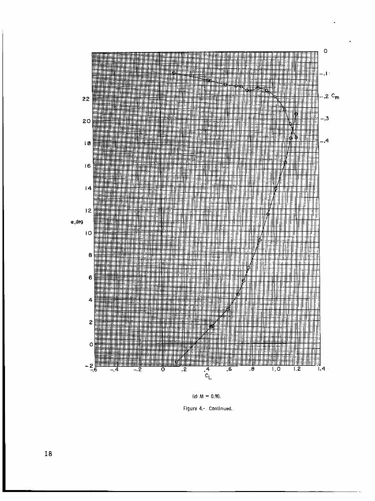
(e) M = 0.90.
Figure 4.- Continued.
0
- . I .
-.2 c,
-.3
-.4
4
18

. I
0
(f) M = 0.925.
Figure 4.- Continued.
19

(gl M = 0.95.
Figure 4.- Continued.
.I
0
-.I c,
- .2
- .3
4
20
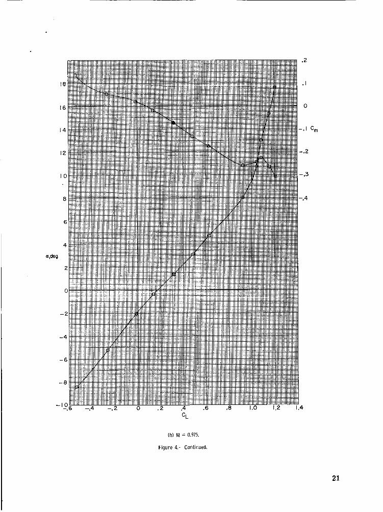
(h) M = 0.975.
Figure 4.- Continued.
.2
.I
0
- . I c,
-.2
- .3
-.4
4
21

.2
.I
0
-.I c,
-.2
-.3
-.4
.4
(i) M = 1.00.
Figure 4.- Continued.
22

.3
2
.' I
0 cm
-.I
-.2
- .3
4 C L
Cj) M = 1.03.
Figure 4.- Continued.
23

(k) M = 1.20.
Figure 4.- Concluded.
.2
. I
0
- . I
-.2
4
24

.
CL Cm
.I 2
.I I
. I O
.o 9
.08
.o 7
.06
0
-. I
- .2
-.3
-. 4
-. 5 , 3 .4 .5 .6 .7 .8 .9 I .o 1.2 I .3 M
Figure 5.- Variation of l i f t -curve slope and static longitudinal-stability parameter w i th Mach number. B = 0'.
25

.o I
0
-.o I
C l
-.o 2
-.o 3
-.O 4
.O 3
.o 2
.o I C"
0
-.o I
. I
0
CY
- . I
.- . i -
(a) M = 0.40.
Figure 6.- Variation of lateral-stability characteristics wi th sideslip angle.

0
CY
-.I
- .2 -
(b) M = 0.60.
Figure 6.- Continued.
27

.O
-.O
-.O
- .O
Cn
.O 3
.02
.o I
C
- .O l
CY
(c ) M = 0.80.
Figure 6.- Continued.
28

.o I
0
-.o I
-.o 2
- a 0 3
.03
.o 2
C" .01
0
-.o I
CY
(d) M = 0.90.
Figure 6.- Continued.
29

CY
(e) M = 0.95.
Figure 6.- Concluded.
30

0
- .2
cnl -.3
-.4
-. 5
.o I
0
C l
-,o I
-. 02
.o 2
-01
c,
0
-. 01
31

Cm
0
-.I
-.2
-.3
.o I
0
-.o I
-.02
.o 2
.o I
C" 0
-.o I
CY
1.0 1.2 I .4
(b) M = 0.60.
Figure 7.- Continued.
32

.01
0
C1
-.o I
-.02
C"
.o 2
.o I
0
(c) M = 0.80.
Figure 7.- Continued.
33

a
Cl
.o I
C
-.o I
-.02
C"
.02
.o I
C
CY
.I
0
-.I 0 .2 .4 .6 1.0 1.2 1.4
.. -.2
CL
(d) M = 0.90.
Figure 7.- Continued.
34

c
.o I
0
-.o I C1
-.02
.o 2
c, .OI
0
0
CY
-.I -
(e) M = 0.95.
Figure 7.- Concluded.
35

,002
0
-.oo 2
5 C
-.004
-.O 06
-.008
C
,006
.004
.002
0
0
- .o I
yP C
-.02
-*o 3
36
Figure 8.- Variation of lateral-stability derivatives with lift coefficient.

' .002
0
-.002
-.004
-.006
M
.004
Cnp .002
n ". 2 .3 .4 .5 .6 .7 .8 .9 1.0 M
0
-.o I
yP C
- -02
-.O 3
Figure 9.- Variation of lateral-stability derivatives w i th Mach number.
NASA-Langley, 1967 L-5234 37