a magnetic climbing robot for marine inspection serviceseprints.qut.edu.au/84011/1/84011.pdf · a...
TRANSCRIPT

92
A Magnetic Climbing Robot for Marine Inspection Services
Kristin Fondahl, DFKI GmbH, Bremen/Germany, [email protected] Markus Eich, DFKI GmbH, Bremen/Germany, [email protected]
Johannes Wollenberg, DFKI GmbH, Bremen/Germany, [email protected] Frank Kirchner, DFKI GmbH, Bremen/Germany, [email protected]
Abstract
Currently, the inspection of sea-going vessels is performed manually. Ship surveyors do a visual
inspection; in some cases they also use cameras and non-destructive testing methods. Prior to a ship
surveying process a lot of scaffolding has to be provided in order to make every spot accessible for
the surveyor. In this work a robotic system is presented, which is able to access many areas of a cargo
hold of a ship and perform visual inspection without any scaffolding. The paper also describes how
the position of the acquired data is estimated with an optical 3D tracking unit and how critical points
on the hull can be marked via a remote controlled marker device. Furthermore first results of
onboard tests with the system are provided.
1. Introduction Marine vessels are subject to numerous and regular inspections and maintenance measures. Ship surveyors inspect the vessels on a regular basis. In most of cases, the surveyor performs only a visual inspection. In order to reach each spot on the ship, scaffolding has to be erected in the cargo holds. Typical heights of cargo holds are 15-20 m. Fig.1 shows two parts of a cargo hold of a bulk carrier with different wall structures. The installation of the scaffolding usually takes several days, before the surveyor can start the inspection process. Every day the ship stays in the dock and out of service results in a significant loss of money for the ship owner, making this (currently necessary) preparation time is very expensive. The EU-funded R&D project MINOAS (Marine INspection rObotic Assistant System) addresses this challenge in an attempt to develop concepts for the automation of the ship inspection process.
Fig. 1: One of the four cargo holds of a 10,000 DWT bulk carrier.
The key idea of the project is to develop and test a fleet of semi-autonomous robots which can provide visual data as well as thickness measurement data to the surveyor without the need for setting up scaffolding prior to the inspection process. While the idea to employ robotic agents for the inspection of hazardous environments is not new, see Sawada et al. (1991), Kawaguchi et al. (1995), Pack et al.
(1997), a fully autonomous inspection of a cargo ship still is a long-term goal. The idea of the project is not to develop an autonomous inspection but rather focus on robotic tools that can enhance and simplify the current inspection process.
93
One of the fleet’s robots is a lightweight magnetic crawler which is able to climb along the vertical walls of a vessel. The crawler was introduced in Vögele et al. (2010) and the first design concept was described in Eich and Vögele (2011). The robot provides a live video stream as well as offline images of the ship for later inspection. Apart from the locomotion capability of the inspection system, it is mandatory for the inspection process that the data is localized, i.e. the position of images and video streams are known within the vessel. For this purpose a 3D tracking unit was developed which acquires the position of the magnetic crawler in real-time. This allows a meaningful comparison of inspection data over a vessel’s lifetime, because the exact position of the data can be stored and therefore replicated. A 3D user interface provides the necessary information to the surveyor and allows access to all acquired data within a 3D view. 2. The Lightweight Crawler: Design and Control
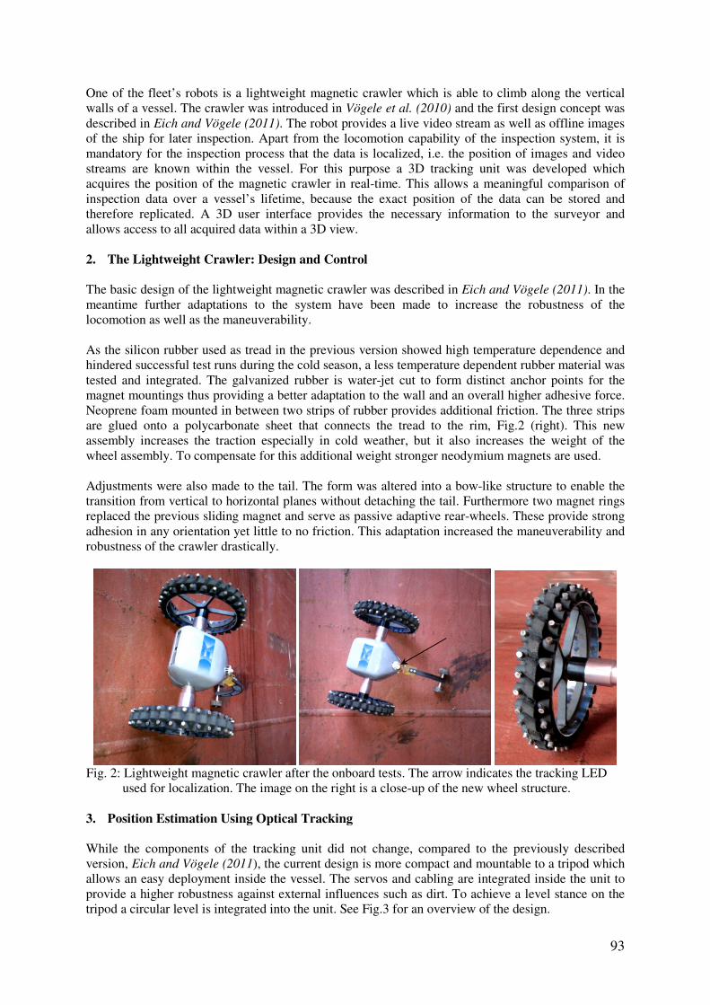
The basic design of the lightweight magnetic crawler was described in Eich and Vögele (2011). In the meantime further adaptations to the system have been made to increase the robustness of the locomotion as well as the maneuverability. As the silicon rubber used as tread in the previous version showed high temperature dependence and hindered successful test runs during the cold season, a less temperature dependent rubber material was tested and integrated. The galvanized rubber is water-jet cut to form distinct anchor points for the magnet mountings thus providing a better adaptation to the wall and an overall higher adhesive force. Neoprene foam mounted in between two strips of rubber provides additional friction. The three strips are glued onto a polycarbonate sheet that connects the tread to the rim, Fig.2 (right). This new assembly increases the traction especially in cold weather, but it also increases the weight of the wheel assembly. To compensate for this additional weight stronger neodymium magnets are used. Adjustments were also made to the tail. The form was altered into a bow-like structure to enable the transition from vertical to horizontal planes without detaching the tail. Furthermore two magnet rings replaced the previous sliding magnet and serve as passive adaptive rear-wheels. These provide strong adhesion in any orientation yet little to no friction. This adaptation increased the maneuverability and robustness of the crawler drastically.
Fig. 2: Lightweight magnetic crawler after the onboard tests. The arrow indicates the tracking LED used for localization. The image on the right is a close-up of the new wheel structure.
3. Position Estimation Using Optical Tracking While the components of the tracking unit did not change, compared to the previously described version, Eich and Vögele (2011), the current design is more compact and mountable to a tripod which allows an easy deployment inside the vessel. The servos and cabling are integrated inside the unit to provide a higher robustness against external influences such as dirt. To achieve a level stance on the tripod a circular level is integrated into the unit. See Fig.3 for an overview of the design.

94
Fig. 3: System overview of the tracking unit that localizes the inspection robot within the vessel. The camera is mounted above the laser range finder and both are actuated with the servo motors situated beneath the covers. In order to localize the crawler inside the vessel information from the two Dynamixel RX-28 servo motors, one Hokuyo laser scanner and one monocular Guppy F-036C camera are fused. The LED mounted on the crawler, Fig.2, is tracked by the monocular camera using Difference of Gaussian, Lowe (2004). The discrepancy between the current and desired position is mapped to servo motor commands to hold the crawler in focus. The 3D position is calculated based on distance measurements provided by the laser and current angles of the servo motors resulting in a 3-dimensional point which is sent to the user interface described in Section 4. Using a laser range finder instead of a stereo camera rig for depth measurements saves computation time and is more accurate on larger distances. It is also more practical in our case, since vessels provide relatively homogeneous image content which is generally not beneficial for stereo vision, Barnard (1987). The external position mapping depends on the position of the tracking unit. To generate replicable data over time the exact location of the tracking unit inside the vessel must be known.
Fig. 4: The 3D tracking concept
95
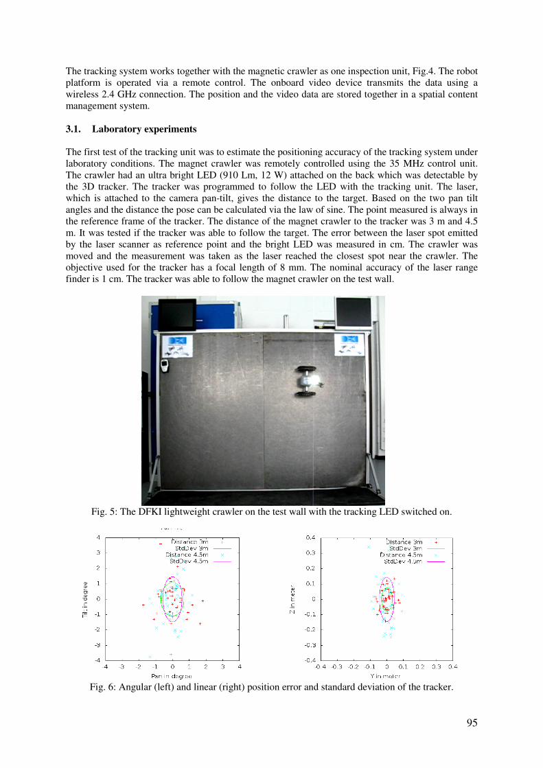
The tracking system works together with the magnetic crawler as one inspection unit, Fig.4. The robot platform is operated via a remote control. The onboard video device transmits the data using a wireless 2.4 GHz connection. The position and the video data are stored together in a spatial content management system. 3.1. Laboratory experiments The first test of the tracking unit was to estimate the positioning accuracy of the tracking system under laboratory conditions. The magnet crawler was remotely controlled using the 35 MHz control unit. The crawler had an ultra bright LED (910 Lm, 12 W) attached on the back which was detectable by the 3D tracker. The tracker was programmed to follow the LED with the tracking unit. The laser, which is attached to the camera pan-tilt, gives the distance to the target. Based on the two pan tilt angles and the distance the pose can be calculated via the law of sine. The point measured is always in the reference frame of the tracker. The distance of the magnet crawler to the tracker was 3 m and 4.5 m. It was tested if the tracker was able to follow the target. The error between the laser spot emitted by the laser scanner as reference point and the bright LED was measured in cm. The crawler was moved and the measurement was taken as the laser reached the closest spot near the crawler. The objective used for the tracker has a focal length of 8 mm. The nominal accuracy of the laser range finder is 1 cm. The tracker was able to follow the magnet crawler on the test wall.
Fig. 5: The DFKI lightweight crawler on the test wall with the tracking LED switched on.
Fig. 6: Angular (left) and linear (right) position error and standard deviation of the tracker.
96
The error in the angles and distance is depicted in Fig.6. The experiment showed that the distance error was within the range of 10 cm at a distance of 3 m and within 20 cm range at a distance of 4.5 m. This corresponds to an error of ± 2° at the 3 m distance and ± 3° at the 4.5 m distance.
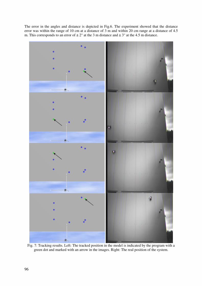
Fig. 7: Tracking results. Left: The tracked position in the model is indicated by the program with a
green dot and marked with an arrow in the images. Right: The real position of the system.

97
Further testing was carried out on an outer metallic wall with a distance of 6 m to the tracking unit and a larger width and height to test a wider range of the tracker. The position error of the tracking unit in these experiments could not be measured exactly due to the height, but lay in the range of 30 cm for all angles. Fig.7 compares the tracked and real positions of the lightweight crawler in these trials. 3.2. User Interface and 3D Representation
For a user friendly inspection process, a graphical user interface (GUI) was added to the system where all data is easily accessible. Since positional information sent by the tracking unit and visual data sent by the camera are transmitted separately the user interface synchronizes all incoming data based on time stamps and constructs data items containing aligned positional and visual data. For an overview of the process, see Fig.8. ROS (Robot Operating System) is a communication middleware for robotic applications and takes care of the sensor data processing, Quigley et al. (2009). In the left part of the interface, Fig.9, data items collected while the crawler moves along the wall are displayed in a list. In the right part, a 3D view of the vessel including a blob-like visualization of data items is given. It is possible to inspect data by selection either inside the list or directly inside the 3D environment, which in the latter case opens the corresponding item on the left. Data items are organized into “runs” whereby a run represents an entire acquisition process while the crawler moves along the wall. This assists inspection of vessels over their life time in making a comparison of data from different time periods possible. Since the availability and interchangeability of data is a common problem in the inspection of a vessel, Bijwaard et al. (2009), standard XML-Files are used to save all information concerning one run. As the crawler provides offline visual data as well, an import for videos is available which automatically synchronizes the input video with the temporally closest item in the currently considered run. The timestamp of the video is extracted from its meta-data.
Fig. 8: Workflow of the visualization
Fig. 9: GUI displaying three data items. One item is selected for further inspection.
98
4. Marking Defects on a Vessels Hull During the first two stages of the inspection process, the surveyor will make a preliminary evaluation of the corrosion and defects of the ship hull. In some cases the surveyor wants to mark the defects found during this process for later inspection. This is currently done with a pen or paint, Fig.10.
Fig. 10: Defects on a vessel are marked directly by the surveyor
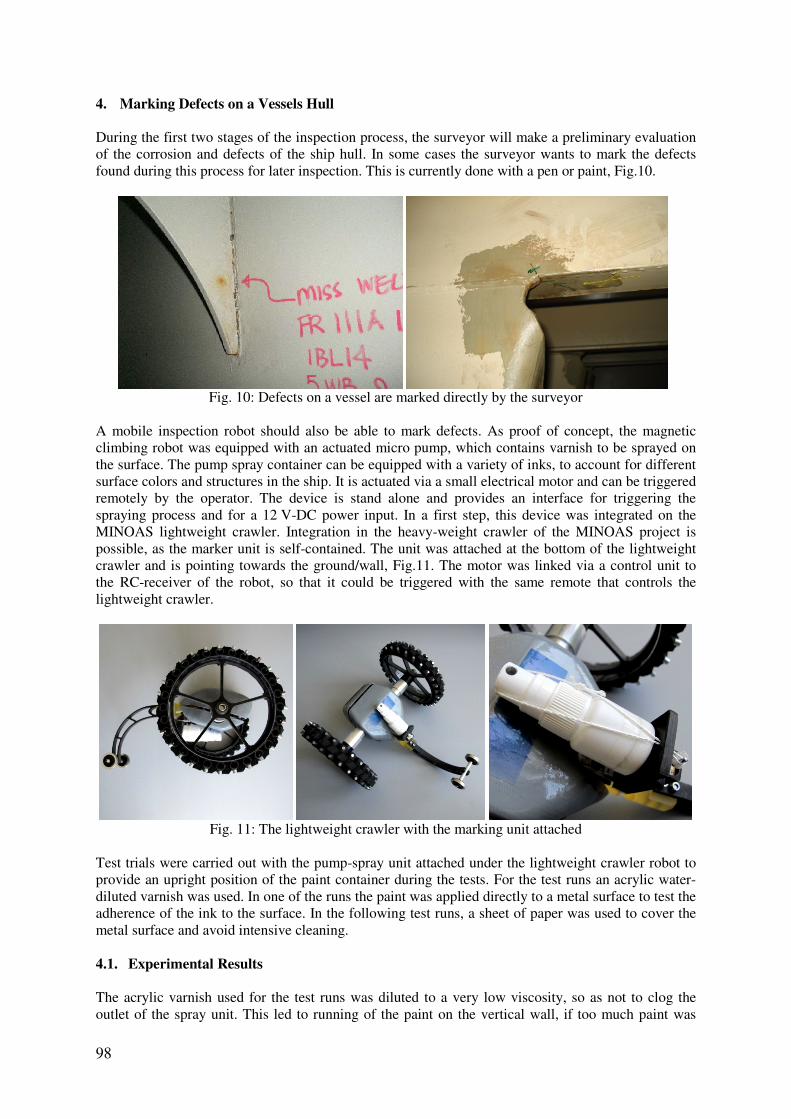
A mobile inspection robot should also be able to mark defects. As proof of concept, the magnetic climbing robot was equipped with an actuated micro pump, which contains varnish to be sprayed on the surface. The pump spray container can be equipped with a variety of inks, to account for different surface colors and structures in the ship. It is actuated via a small electrical motor and can be triggered remotely by the operator. The device is stand alone and provides an interface for triggering the spraying process and for a 12 V-DC power input. In a first step, this device was integrated on the MINOAS lightweight crawler. Integration in the heavy-weight crawler of the MINOAS project is possible, as the marker unit is self-contained. The unit was attached at the bottom of the lightweight crawler and is pointing towards the ground/wall, Fig.11. The motor was linked via a control unit to the RC-receiver of the robot, so that it could be triggered with the same remote that controls the lightweight crawler.
Fig. 11: The lightweight crawler with the marking unit attached
Test trials were carried out with the pump-spray unit attached under the lightweight crawler robot to provide an upright position of the paint container during the tests. For the test runs an acrylic water-diluted varnish was used. In one of the runs the paint was applied directly to a metal surface to test the adherence of the ink to the surface. In the following test runs, a sheet of paper was used to cover the metal surface and avoid intensive cleaning. 4.1. Experimental Results
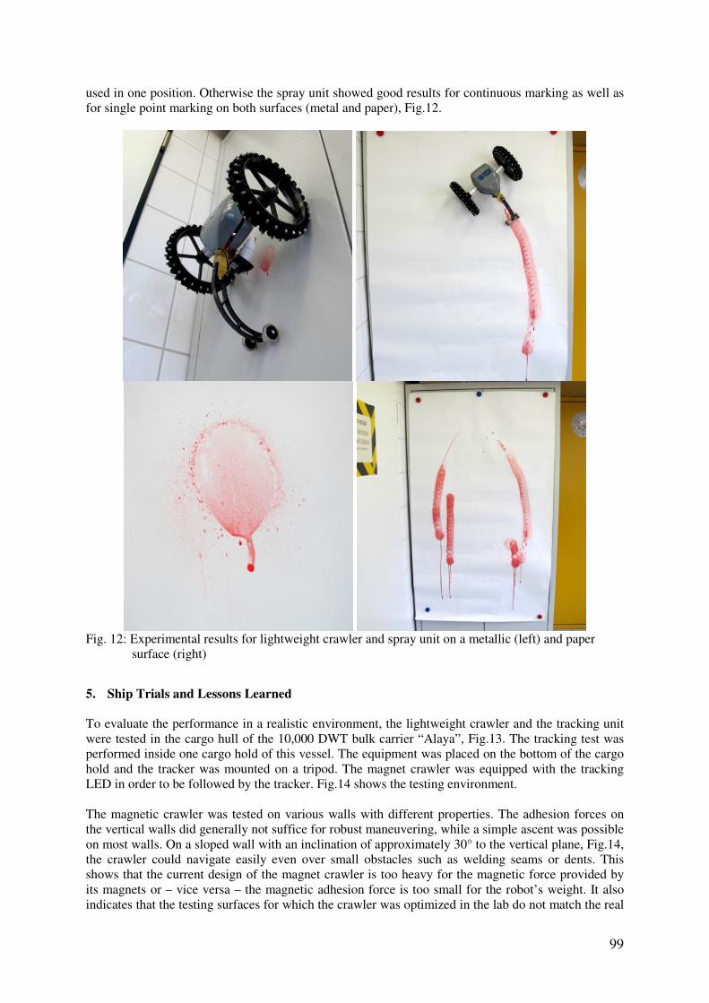
The acrylic varnish used for the test runs was diluted to a very low viscosity, so as not to clog the outlet of the spray unit. This led to running of the paint on the vertical wall, if too much paint was
99
used in one position. Otherwise the spray unit showed good results for continuous marking as well as for single point marking on both surfaces (metal and paper), Fig.12.
Fig. 12: Experimental results for lightweight crawler and spray unit on a metallic (left) and paper surface (right)
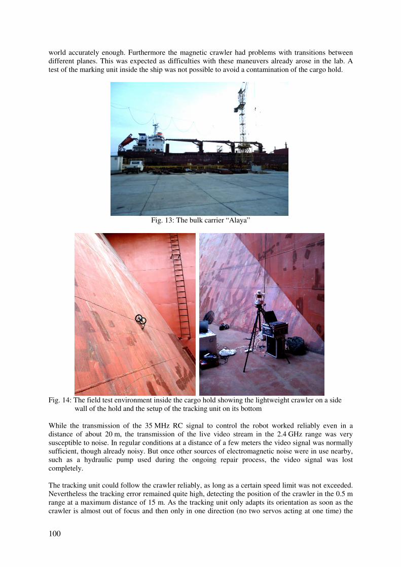
5. Ship Trials and Lessons Learned To evaluate the performance in a realistic environment, the lightweight crawler and the tracking unit were tested in the cargo hull of the 10,000 DWT bulk carrier “Alaya”, Fig.13. The tracking test was performed inside one cargo hold of this vessel. The equipment was placed on the bottom of the cargo hold and the tracker was mounted on a tripod. The magnet crawler was equipped with the tracking LED in order to be followed by the tracker. Fig.14 shows the testing environment. The magnetic crawler was tested on various walls with different properties. The adhesion forces on the vertical walls did generally not suffice for robust maneuvering, while a simple ascent was possible on most walls. On a sloped wall with an inclination of approximately 30° to the vertical plane, Fig.14, the crawler could navigate easily even over small obstacles such as welding seams or dents. This shows that the current design of the magnet crawler is too heavy for the magnetic force provided by its magnets or – vice versa – the magnetic adhesion force is too small for the robot’s weight. It also indicates that the testing surfaces for which the crawler was optimized in the lab do not match the real
100
world accurately enough. Furthermore the magnetic crawler had problems with transitions between different planes. This was expected as difficulties with these maneuvers already arose in the lab. A test of the marking unit inside the ship was not possible to avoid a contamination of the cargo hold.
Fig. 13: The bulk carrier “Alaya”
Fig. 14: The field test environment inside the cargo hold showing the lightweight crawler on a side wall of the hold and the setup of the tracking unit on its bottom While the transmission of the 35 MHz RC signal to control the robot worked reliably even in a distance of about 20 m, the transmission of the live video stream in the 2.4 GHz range was very susceptible to noise. In regular conditions at a distance of a few meters the video signal was normally sufficient, though already noisy. But once other sources of electromagnetic noise were in use nearby, such as a hydraulic pump used during the ongoing repair process, the video signal was lost completely. The tracking unit could follow the crawler reliably, as long as a certain speed limit was not exceeded. Nevertheless the tracking error remained quite high, detecting the position of the crawler in the 0.5 m range at a maximum distance of 15 m. As the tracking unit only adapts its orientation as soon as the crawler is almost out of focus and then only in one direction (no two servos acting at one time) the

101
tracking curve provided by the unit is a step curve, while the crawler itself can follow smooth lines. The data matching of the acquired images to the detected location worked well, although only one measurement could be completed due to the problems with the video transmission. 6. Conclusion and Future Work The new developments in the inspection system presented include an optimized mechanical design of both the crawler robot itself and the tracking unit. Furthermore the software to localize the data taken by the lightweight crawler and its graphical representation for the user is introduced. The presented marking unit can provide a way to label defects inside the hull for later inspection. The lab-trials and the real-world tests aboard the “Alaya” showed some issues that need to be corrected, before an application of this robotic system becomes a useful addition to conventional inspections. On the mechanical side the robot needs stronger magnets to provide a robust attachment to the steel walls in any orientation. Simply replacing the current magnets with stronger ones though, might lead to different issues that have to be considered, such as a decreasing motor speed due to higher loads or a possible failure of the current mounting system resulting in a loss of the magnets during the runs. To test possible outcomes the testing surface in the lab is to be adapted to resemble an actual ship wall more closely and allow for meaningful experiments without the need to board a ship. Stronger magnets may also help to transit from a horizontal to a vertical surface or between two vertical surfaces. Otherwise a new wheel design, e.g. Tâche et al. (2009), might help overcome these problems. To make a use of the marking unit in a real world environment, it needs to be equipped with a more suitable varnish for metallic surfaces. This varnish must not clog the outlet of the spray container and has to be suitable for multiple if not all surfaces in a ship. Another option for a marking system may be the use of a servo actuated marker pen. The transmission problems of the video images have to be prevented, as other repairs cannot be put to a hold during the inspections. Therefore a new video transmission was later integrated into the robot with a 5.8 GHz submission rate and 2.5 times stronger signal. The transmission remains to be tested onboard a ship but the noise ratio inside the lab decreased drastically with this setup. On the software side the tracking algorithms need to be optimized and sped up to enable the tracking unit to follow the robot robustly at all times. This could be achieved by using for instance a particle filter which estimates the motion before the motion is executed, Fox et al. (1999). The synchronization and matching of the sensor data with the localization data works well and reliably. Yet some problems remain: To actually use the data, an accurate computer model of the inspected ship is needed, which, oftentimes, is not available for the inspection process. Another robot of the MINOAS fleet might provide this model in later adaptations, namely the flying inspection unit, Ortiz et al. (2011). Furthermore the tracking unit needs reproducible anchor points inside the ship. This might be put into practice by welding markers (i.e. screw nuts) to the anchor points or otherwise marking them inside the ship. Or it might be possible to map the anchor points virtually and retrieve them during the inspection process by measurements from certain landmarks in the hull. Nevertheless after the optimization of these factors the lightweight crawler can serve as a useful tool during the inspection of large cargo holds or even (with a watertight cover) for the outer hull. Before that can happen not only the technical problems need to be solved but also a wider acceptance of the reliability of such robotic tools for the commercial use has to be sought. Acknowledgments This work has been funded by the European Commission under the project MINOAS (SCP8-GA-2009-233715).

102
References BARNARD, S.T. (1987), A stochastic approach to stereo vision, In Readings in Computer Vision: Issues, Problems, Principles, and Paradigms, Morgan Kaufmann Publ., pp.21-25. BIJWAARD, G. E.; KNAPP, S. (2009), Analysis of ship life cycles - The impact of economic cycles
and ship inspections, Marine Policy 33/2, pp.350-369 EICH, M.; VÖGELE, T. (2011), Design and control of a lightweight magnetic climbing robot for
vessel inspection, 19th Mediterranean Conf. Control & Automation (MED), Corfu, pp.1200-1205 FOX, D.; BURGARD, W.; DELLAERT, F.; THRUN, S. (1999), Monte Carlo localization: Efficient
position estimation for mobile robots, 16th Nat. Conf. Artificial Intelligence, Orlando KAWAGUCHI, Y.; YOSHIDA, I.; KURUMATANI, H.; KIKUTA, T.; YAMADA, Y. (1995), Internal pipe inspection robot, IEEE Int. Conf. Robotics and Automation, Nagoya, Vol.1, pp.857-862 LOWE, D.G. (2004), Distinctive image features from scale-invariant keypoints, Int. J. Computer Vision 60/2, pp.91-110. ORTIZ, A.; BONNIN-PASCUAL, F.; GARCIA-FIDALGO, E.; BELTRAN, J.P. (2011), A control
software architecture for autonomous unmanned vehicles inspired in generic components, 19th Mediterranean Conf. Control & Automation (MED), Corfu, pp.1217-1222 PACK, R.T.; CHRISTOPHER, J.L.; KAWAMURA, K. (1997), A Rubbertuator-based structure-climbing inspection robot, IEEE Int. Conf. Robotics and Automation, Albuquerque, Vol.3, pp.1869-1874 QUIGLEY, M.; GERKEY, B.; CONLEY, K.; FAUST, J.; FOOTE, T.; LEIBS, J.; BERGER, E.; WHEELER, R.; NG, A. (2009), ROS: An open-source robot operating system, IEEE Int. Conf. Robotics and Automation, Kobe, pp.151-170 SAWADA, J.; KUSUMOTO, K.; MAIKAWA, Y.; MUNAKATA, T.; ISHIKAWA, Y. (1991), A
mobile robot for inspection of power transmission lines, IEEE Trans. Power Delivery 6/1, pp.309-315 TÂCHE, F.; FISCHER, W.; CAPRARI, G.; SIEGWART, R.; MOSER, R.; MONDADA, F. (2009), Magnebike: A magnetic wheeled robot with high mobility for inspecting complex shaped structures, J. Field Robotics 26(5), pp.453-476 VÖGELE, T.; EICH, M.; GRIMMINGER, F.; FONDAHL, K. (2010), A hybrid legged wheel climbing robot for marine inspection, 13th Int. Conf. Climbing and Walking Robots and the Support Technologies for Mobile Machines (CLAWAR), Nagoya, pp.1-8