a magnetic journal bearing - meet philips research bound... · 232 phillps technical review volume...
TRANSCRIPT
232 PHILlPS TECHNICAL REVIEW VOLUME 22
A MAGNETIC JOURNAL BEARING
by F. T. BACKERS.
The supporting of a rotating shaft in such a way that no material contact is made with theshaft can be of importance for technical applicaiions. Cases in point are where the friction orwear must be particularly small, where contamination by lubricants is inadmissible or wherethe lubricating oilwould decompose under the influence of radiation (in a nuclear reactor, forexample). The article below considers the theory of a shaft which is' held in suspension by mag-netic fields, and compares the theory with the results of measurements which have been made on"magnetic bearings" of various dimensions.
Rotating shafts are supported. by bearings, andthe necessary reactions are provided by materialcontact between shaft and bearing. The friction andwear which are the unavoidable consequence of thiscontact, are limited as much as possible by usinglubricants.
The idea of reducing the friction and wear to nilby making the shaft "float" is attractive. Oneapproach to this problem is based on levitation bythe application of magnetic fields 1). Those methodswhich rely on the use of a diamagnetic body or of asuperconductor 1) are for practical reasons not veryuseful, Also methods in which the supporting forcecomes from electromagnets are open to the objec-tion that a continuous supply of energy is necessaryfor levitation. The only remaining alternative possi-bility, using permanent magnets to provide thesupport, has been described in a patent application 2)but, as far as we know, has never been realized.In the Philips laboratory at Eindhoven, a study hasbeen made of such magnetic bearings. A numberhave been constructed and measurements on themhave verified the theory.
Descrlption of the magnetic hearing
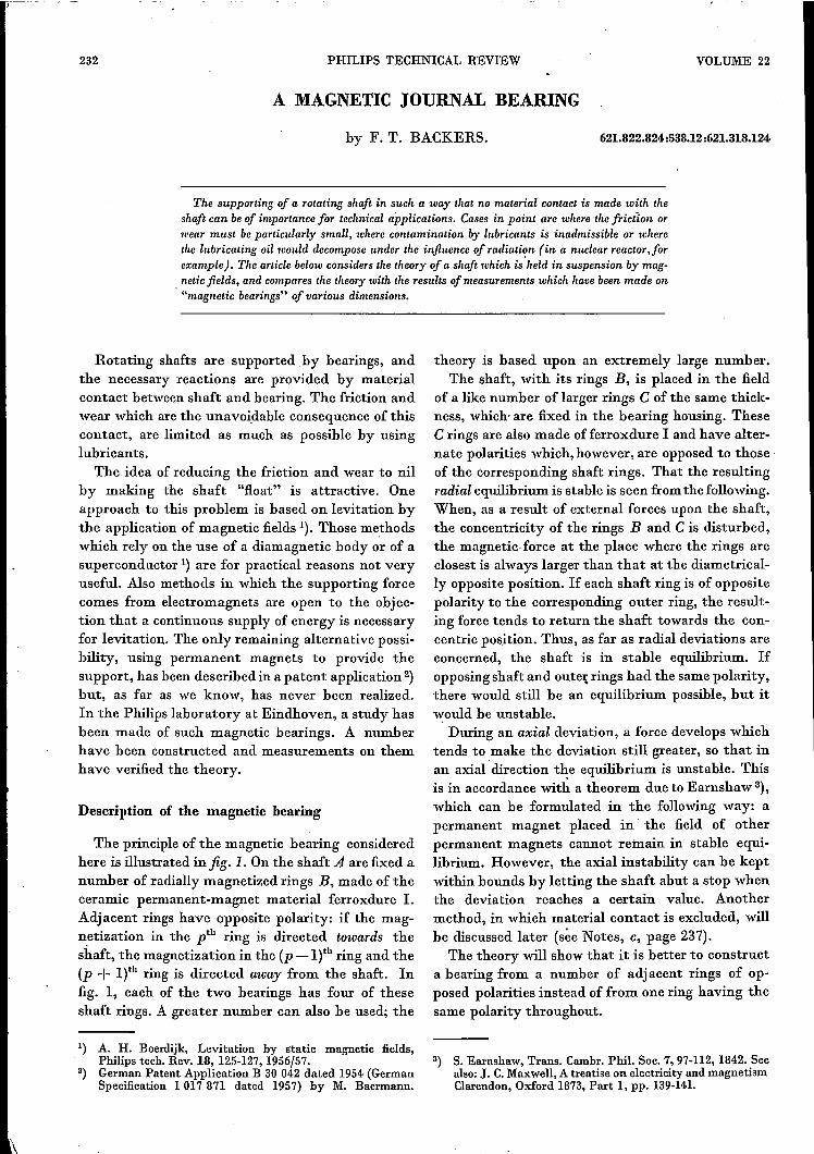
The principle of the magnetic bearing consideredhere is illustrated in fig. 1. On the shaft A are fixed anumber of radially magnetized rings B,made of theceramic permanent-magnet material ferroxdure 1.Adj acent rings have opposite polarity: if the mag-netization in the pth ring is directed towards theshaft, the magnetization in the (p _l)th ring and the(p + l)th ring is directed away from the shaft. Infig. 1, each of the two bearings has four of theseshaft rings. A greater number can also he used; the
1) A. H. Boerdijk, Levitation by static magnetic fields,Philips tech. Rev. 18, 125-127, 1956/57.
2) German Patent Application B 30 042 dated 1954 (GermanSpecification 1 017 871 dated 1957) by M. Baermann.
621.822.824:538.12:621.318.124
theory is based upon an extremely large number.The shaft, with its rings B, is placed in the field
of a like number of larger rings C of the same thick-ness, which- are fixed in the bearing housing. TheseC rings are also made of ferroxdure I and have alter-nate polarities which, however, are opposed to thoseof the corresponding shaft rings. That the resultingradial equilibrium is stable is seen from the following.When, as a result of external forces upon the shaft,the concentricity of the rings Band C is disturbed,the magnetic.force at the place where the rings areclosest is always larger than that at the diametrical-ly opposite position. If each shaft ring is of oppositepolarity to the corresponding outer ring, the result-ing force tends to return the shaft towards the con-centric position. Thus, as far as radial deviations areconcerned, the shaft is in stable equilibrium. Ifopposing shaft and outer rings had the same polarity,there would still be an equilibrium possible, but itwould be unstable.
During an axial deviation, a force develops whichtends to make the deviation still greater, so that inan axial direction the equilibrium is unstable. Thisis in accordance with a theorem due to Earnshaw 3),which can be formulated in the following way: apermanent magnet placed in' the field of otherpermanent magnets cannot remain in stable equi-librium. However, the axial instability can be keptwithin bounds by letting the shaft abut a stop whenthe deviation reaches a certain value. Anothermethod, in which material contact is excluded, willhe discussed later (see Notes, c, page 237).
The theory will show that it is better to constructa bearing from a number of adjacent rings of op-posed polarities instead of from one ring having thesame polarity throughout.
3) S. Earnshaw, Trans. Cambr. Pbil. Soc. 7, 97-112, 1842. Seealso: J. C.Maxwell, A treatise on electricity and magnetismClarendon, Oxford 1873, Part 1, pp. 139-141.
1960/61, No. 7 MAGNETIC JOURNAL BEARING 233
Fig. 1. Diagram showing the principle of a shaft with two magnetic bearings. The innerrings B are fixed on the shaft A. This assembly can rotate in the field of the stationaryouter rings C. All the rings are magnetized radially. Adjacent rings are magnetized inopposite directions; likewisecorresponding inner and outer rings. H housing.
The theory of the magnetic bearing
In the magnetic bearing, two characteristicquantities occur: the radial carrying capacity Fo,being the external force upon the shaft which isnecessary to bring the shaft rings into contact withthe outer rings; and the radial stiffness S, denotingthe force per unit displacement in a radial direction.These two quantities are calculated below.We consider an infinitely large flat plate C of
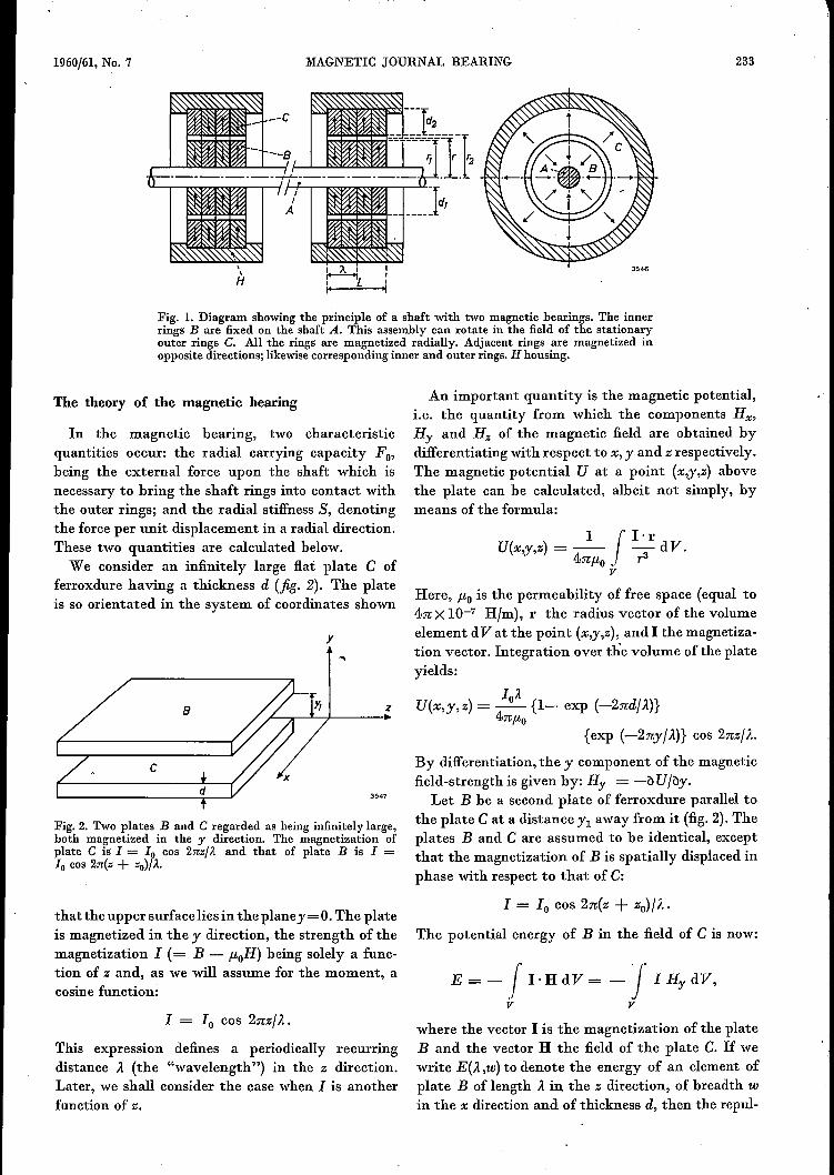
ferroxdure having a thickness d (jig. 2). The plateis so orientated in the system of coordinates shown
y
8
c
Fig. 2. Two plates Band C regarded as being infinitely large,both magnetized in the y direction. The magnetization ofplate C is I = 10 cos 2nz/}. and that of plate B is I =10 cos 2n(z + zo)/}.'
that the upper surfacelies in the plane y=O. The plateis magnetized in the y direction, the strength of themagnetization I (= B - ;.toH) being solely a func-tion of z and, as we will assume for the moment, acosine function:
I = 10 cos 2nzjA.
This expression defines a periodically recurringdistance A (the "wavelength") in the z direction.Later, we shall consider the case when I is anotherfunction of z.
An important quantity is the magnetic potential,i.e. the quantity from which the components Hx,Hy and Hz of the magnetic field are obtained bydifferentiating with respect to x, y and z respectively.The magnetic potential U at a point (x,y,z) abovethe plate can be calculated, albeit not simply, bymeans of the formula:
z
1 r I'rU(x,.y,z) = -- -- dV.4n;.to. r3
vHere, ;.to is the permeability of free space (equal to4.nX 10-7 Hjm), l' the radius vector of the volumeelement dVat the point (x,y,z), and I the magnetiza-tion vector. Integration over the volume ofthe plateyields:
loAU(x,y,z) = - {1- exp (-2ndjA)}
4n;.to{exp (-2nyjA)} cos 2nzjA.
3547
By differentiation, the y component of the magneticfield-strength is given by: Hy = -b U jby.
Let B be a second plate of ferroxdure parallel tothe plate C at a distance Yl away from it (fig. 2). Theplates Band C are assumed to be identical, exceptthat the magnetization of B is spatially displaced inphase with respect to that of C:
1= 10 cos 2n(z + Zo)jA.
The potential energy of B in the field of C is now:
E = - .r I· H dV = - I I u; dV,
v v
where the vector I is the magnetization of the plateB and the vector H the field of the plate C. If wewrite E(A,W) to denote the energy of an element ofplate B of length A in the z direction, of breadth win the x direction and of thickness d, then the repul-
234 PHILIPS TECHNICAL REVIEW VOLUME 22
sive force to which B is subjected in the field of Cis,per unit area:
1 oE(À,w)ay=--
wÀ by
In this way it is found that:
12ay = - _0_ {1- exp (- 2ndIÀ)}2
4,uo{exp (-2ny 11À)} cos 2nzolÀ •
If only Á is varied in this expression, it appears thatay approaches zero in the two limiting cases À ~ 0and Á ___,..00 •In the first case, the opposed polaritiesapproach infinitely closely to one another so thatthey neutralize each other's effect. In the second case,the magnetic field is contained totally within theferroxdure and there is thus no external field present;this can be seen when it is realized that H in theinfinitely large plate must be constant (lines of forceparallel) and can therefore only have the value zero,since the lines of force outside the plate are infinitelylong. The existence of two limiting cases suggeststhat somewhere in between there should he an op-timum value of À.
Since ay is positive in the direction of the positivey axis, a maximum attractive force will he obtainedwhen the phase displacement Zo is equal to zero, i.e.the magnetization of plate B is spatially in phasewith that of C (this can be seen by inspection).Since, in the case of"the magnetic bearing, a maxi-mum repulsive force is required, Zo is chosen equalto iÁ; the magnetization of B is then displaced by ahalf wavelength from that of C. Again, the thicknessd is assumed to be sufficiently large in order to makeexp (-2nd/À) negligible with respect to unity;d = }"for example, makes this term approximately0.002. These considerations lead to:
12ay= _0_ exp (-2nYIIÁ).
4,uo
In order to transferm the flat plates Band Cinto the bearing, we cut pieces of suitable dimen-sions out of the plates and bend these pieces into theform of hollow cylinders, the axes of which are paral-lel with the z axis and whose radial direction corre-sponds to the original y direction. The distance Y1isnow represented by the distance between the shaftrings B and the outer rings C of the bearing de-scribed earlier, and the length (dimension in axialdirection) of a ring is iÁ. It is assumed throughoutthat the repulsive force, acting upon an element ofB, predominantly emanates from a limited area of Cin the immediate vicinity of that element of B.Iftheradius of curvature of the cylinder is large compared
with y., then this small area of C can he regarded all
:flat. The above theory for the ":flat case" can then heapplied to the cylindrical case,i.e. that ofthe bearing.
The radial force acting upon a surface elementLr de, where L is the length of the bearing and r themean radius (fig. I), is now: .
dFy = ayLr de. (2)
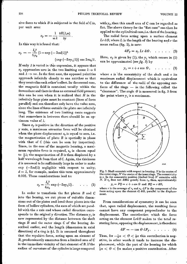
Here, ay is given by (1); the Yl which occurs in (1)can be approximated (see fig. 3) by
Yl = c+e cos e, (3)
where e is 'the eccentricity of the shaft and c itsmaximum radial displacement which is equivalentto the difference of the radii of the opposing sur-faces of the rings - in the following called the"clearance". The angle e is measured in fig. 3 fromthe point where Yl is a maximum.
(1)
Fig. 3. Shaft eccentric with respect to bearing. N is the centre ofthe outer rings, N' the centre of theinnerrings. The eccentricityis e. In the concentric position (dashed line) N' coincides withN. If 71 does not differ greatly from 72, then, approximately:
Yl = PQ = c+ e cos e and RQ = 7 de,where 7 is the average of 71 and 72, dF is the component of theforce acting upon the element 7L de, parallel to the displace-ment.
From considerations of symmetry it can be seenthat, upon radial displacement, the resulting forcecannot have any component perpendicular to thedisplacement. The contribution which the forceacting on the element Lrde makes to the total re-storing force, opposing the displacement, is therefore:
dF = -cos e dFy. (4)
Thus, for 4n < e < in this contribution is neg-ative, in other words it tends to increase the dis-placement, while the part of the bearing for whichin < e < tn makes, a positive contribution. After
1960/61, No. 7 MAGNETIC JOURNAL BEARING 235
integrating equation (4) over e, and substitutingfrom equations (1), (2) and (3), the total restoringforce F is found, this force being a maximum whenthe eccentricity e is equal to the clearance c, andbeing then equivalent to the radial carrying capac-ity Fo which was what wc set out to calculate. Wenow have:
n
F. = -A exp (-b) r cos e exp (-b' cos e) de,.1o
where A = LrI02/2p'0, b = 21fc/J.. and b' = 2ne/J...The maximum value of F, i.e. the radial carryingcapacity Fo, follows immediately by putting b' = b,i.e. c = e.
From a numerical calculation of Fo as a functionof b, it appears that Fo has a fairly flat maximum forvalues of b in the neighbourhood of 1. From this itfollows that the relation
b = 2nc/J.. = 1
defines an optimally dimensioned bearing. The axiallength iJ.. of each ring should thus be approxi-mately three times the clearance c. The magnitudeof the carrying capacity is then 0.655 A, i.e.
(Fo)max = 0.655 LrI02/2p'0' (5b)
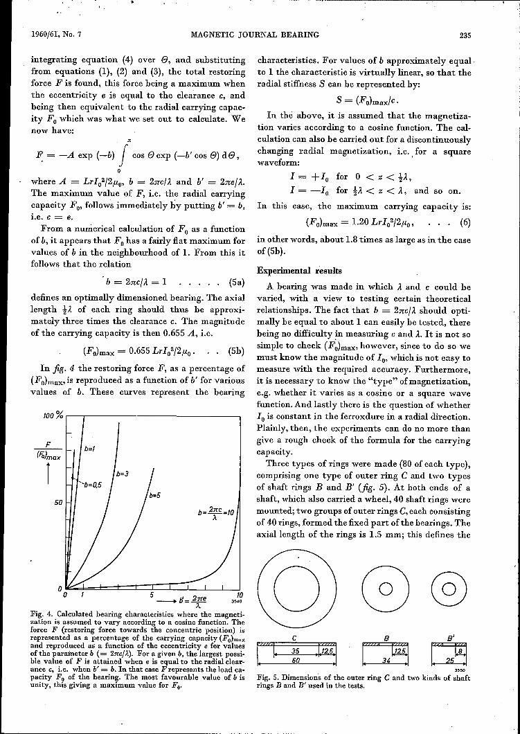
In fig. 4 the restoring force F, as a percentage of(Fo)max, is reproduced as a function of b' for variousvalues of b. These curves represent the bearing
lOO % r-----.-----.--------------,
b=1F
(Fo}max
150
b= 2:rrc=10À
Fig. 4. Calculated bearing characteristics where the magneti-zation is assumed to vary according to a cosine function. Theforce F (restoring force towards the concentric position) isrepresented as a percentage of the carrying capacity (Fo)m."and reproduced as a function of the eccentricity e for valuesof the parameter b (= 2nc/ it). For a given b, the largest possi-ble value of F is attained when e is equal to the radial clear-ance c, i.e. when b' = b. In that case F represents the load ca-pacity Fo of the bearing. The most favourable value of b isunity, this giving a maximum value for Fo.
characteristics. For values of b approximately equal.to 1the characteristic is virtually linear, so that theradial stiffness S can be represented by:
S = (Fo)max/c.
In the above, it is assumed that the magnetiza-tion varies according to a cosine function. The cal-culation can also be carried out for a discontinuouslychanging radial magnetization, i.e .. for a squarewaveform:
1= +10 for 0 < z < i;",I = -10 for iJ.. < z < J.., and so on.
In this case, thc maximum carrying capacity is:
(6)
in other words, about 1.8 times as large as in the caseof (5b).
(5a)Experimental results
A bearing was made in which J.. and c could bevaried, with a view to testing certain theoreticalrelationships. The fact that b = 2nc/ J.. should opti-mally be equal to about 1 can easily be tested, therebeing no difficulty ~nmeasuring c and J... It is not sosimple to check (Fo)max, however, since to do so wemust know the magnitude of 10,which is not easy tomeasure with the required accuracy. Furthermore,it is necessary to know the "type" ofmagnetization,e.g. whether it varies as a cosine or a square wavefunction. And lastly there is 'the question of whether10is constant in the ferroxdure in a radial direction.Plainly, then, the experiments can do no more thangive a rough check of the formula for the carryingcapacity.
Three types of rings were made (80 of each type),comprising one type of outer ring C and two typesof shaft rings Band B' (fig. 5). At both ends of ashaft, which also carried a wheel, 4·0shaft rings weremounted; two groups of outer rings C, each consistingof 4·0rings, formed the fixed part ofthe bearings. Theaxiallength of the rings is 1.5 mm; this defines the
@a'
~
c
[2221
1. 35 ~11~1:160
.:12:5::3'>0
Fig. 5. Dimensions of the outer ring C and two kinds of shaftrings B and .B' used in the tests.
236 PHILlPS TECHNICAL REVIEW VOLUMEc22
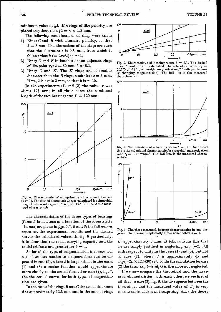
minimum value of tÀ. If n rings of like polarity areplaced together, then tÀ = n X 1.5 mm.
The following combinations of rings were tried:1) Rings C and B with alternate polarity, so that
À = 3 mm. The dimensions of the rings are suchthat the clearance c is 0.5 mm, from which itfollows that b (= 2nc/ À) is f"'OooJ 1.
2) Rings C and B in batches of ten adjacent ringsoflike polarity: À = 30 mm, b ~ 0.1.
3) Rings C and BI. The BI ring!'! are of smallerdiameter than the B rings, such that c= 5 mm.Here, À is again 3 mm, so that b is ,...._,10.
In the experiments (1) and (2) the radius r wasabout 17t mm; in all three cases the combinedlength of the two bearings was L = 120 mm.
15N
b=1//////
///
/l/ V//
/ V//
~/ /'
/" -:V//~y[_P:
F
110
5
o 0,1 0,2 O,t.mm0,3__ e
Fig. 6. Characteristic of an optimally dimensioned bearing(b = 1).The dashed characteristic was calculated for sinusoidalmagnetization withlo =0.17WhJm2• The full Iine is the meas-ured characteristic. .
The characteristics of the three types of bearings(force F in newtons as a function of the eccentricitye in mm) are given infigs. 6,7,8 and 9; the full curvesrepresent the experimental results and the dashedcurves the calculated values. In fig. 9 particularly,it is clear that the radial carrying capacity and theradial stiffness are greatest for b = 1.
As far as the type of magnetization is concerned,a good approximation to a square form can be ex-pected in case (2), where À is large, whilst in the cases(1) and (3) a cosine function would approximatemore closely to the actual form. For case (2), fig. 7,the theoretical curves for both types of magnetiza-tion are given.
In the case of the rings Band Cthe radial thicknessd is approximately 12.5 mm and in the case of rings
5N~-----r----~r-----'-~--~----·-'3,. ..........F ~.....
r
o,T 0,2 o,t.mm 3m0,3_e
Fig. 7. Characteristic of hearing where b = 0.1. The dashedlines 1 and 2 are calculated characteristics with 10 =0.17WhJm2 (1 for sinusoidalmagnetization, 2 for discontinuous-ly changing magnetization). The full line is the measuredcharacteristic.
TON
b=TO1
IIII
/III
l,
v',,/ _-/-- -'"
F
15
o o t.mm3 3553--_eFig. 8. Characteristic of a hearing where b = 10. The dashedline is the calculated characteristic for sinusoidal magnetizationwith 10 = 0.17 WhJm2• The full line is the measured charac-teristic.
TON
I-
b=T
II
V~,~
F
13551
5
oo 2 3 I.mm- __ eFig. 9. The three measured hearing characteristics in one dia-gram. The hearing is optimally dimensioned when b = 1.
BI approximately 8 mm. It follows from this that'we are amply justified in neglecting exp (-2nd/À)with respect to unity in the cases (1) and (3), but notin case (2), where d is approximately tÀ andexp (-2n X 12.5/30) ~ 0.07. In the calculation for case(2) the term exp (-2nd/ À) is therefore not neglected.Ifwe now compare the theoretical and the meas-
ured characteristics with each other, we see first ofall that in case (3), fig. 8, the divergence between thetheoretical and the measured value of" Fo is veryconsiderable. This is not surprising, since the theory

1960/61, No. 7 MAGNETIC JOURNAL BEARING 237
supposes the clearance c to be small compared withthe average radius T, and this requirement is notfulfilled here. On the other hand, in cases (1) and (2),it appears that the differences between the theoreti-cal and the measured curves are probably due to anerror in the measurement of the magnetization.The latter was measured in various ways. The aver-age of the measurements was: 10 = 0.17 Wb/m2with a possible error of approximately 20%. Since(Fo)max is proportional to 102,this error can lead toone of approximately 40% in the final result. Assum-ing that the theory is correct and that in case (1) themagnetization followed a cosine function, it followsfrom the measured curve in fig. 6 that: 10 = 0.13Wb/m2. This value does not deviate more than about20% from the average measured value. If we choosethis "corrected" value for calculating the theoreti-cal curves in case (2), fig. 7, then the curve for a dis-continuously changing magnetization more or lesscoincides with the measured curve.It should be added that the measurements of 10
are, in fact, measurements of the remanence orresidual magnetization. This is only equal to themagnetization in the present situation (magnet inthe field of another magnet) if the relative permeabili-ty flr is equal to 1, since an external field H increasesthe magnetization by the amount llo(llr-1)H,which is zero only when Ilr is unity. This is approxi-mately so in the case of ferroxdure, and therefore itmay be assumed that the measurements give theapproximate magnetization of the ferroxdure in theassembled bearing.Another practical advantage of ferroxdure is its
high electrical resistivity, so that very low eddy-current losses occur during the rotation of the shaft.
Notes
a) Both the weight ofthe shaft ring and (Fo)maxincrease linearly with thelength L; however, as theradius T of the bearingis increased, the weightincreases quadraticallywhilst (Fo}max increasesonly linearly. Now, inorder to avoid using upthe whole radial carryingcapacity to maintain theweight of the shaft itselfin the case of large hori-zontal shaft assemblies,we make use of the factthat although the radial
thickness d must be large enough (compared toÀ), it does not have to be so much larger than À.It is therefore possible to make use of hollowshafts of large diameter, fitted with rings of rela-tively small radial thickness. In this way, advantageis taken of the linear increase of (Fo)max withrespect to T, while the weight now increases muchless than proportionally to the square of T.·
With the types ofhearing usedin our experiments,the weight of the shaft complete with rings andwheel was just under 1 kg, i.e. almost as much as thecarrying capacity of the bearing with optimumclearance (b = 1, fig. 6). By means of the measuresjust mentioned, the design can he improved tofulfil practical requirements. Again, a better mate-rial can be used (see the following note).
b} In the foregoing we have been concerned solelywith radially oriented magnetization. The sameformulae also. apply, however, to axial magnetiza-tion of the same rings, although this will not be .further amplified here. One advantage ofaxialmagnetization is that the direction of I is the samethroughout each ring, making it possible to usecrystal-oriented ferroxdure n, which has a higherremanence 4); this is a great advantage since(Fo}max is proportional to 102• The preferred direc-tion of magnetization in the ferroxdure n shouldthen coincide with the axial direction of the rings.c) It is assumed that the shaft and outer rings are
directly opposite each other (see theory; Zo = }À).If this is not the case, the carrying capacity mustbe multiplied by cos 2nzo/ À, which indicates that
4) A. L. Stuijts, G. W. Rathenau and G. H. Weber, Ferrox-dure II and Ill, anisotropic permanent magnet materials,Phi~ips tech. Rev. 16, 141-147, 1954/55.
Fig. 10. System for stabilizing the shaft in an axial direction. D and D' are ferroxcube diskswhich can be attracted by electromagnets E and E', excited by coils F. and F'. The self-inductance of the coilsH and H' on the cores G and G' is dependent upon the distance tothe disks D and D'. The magnetic bearings themselves are omitted here.

238 PHILIPS TECHNICAL REVIEW VOLUME 22
Fig. ll. Shaft A with magnetic bearings M and M', ferroxcube disks D and D' and axialstabilizers Sand S'.
good positioning in the axial direction is important,especially when À is small. A method has been de-veloped for locating the shaft in an axial directionwithout material contact. Use is made of an elec-tro-mechanical servo-mechanism, the principle ofwhich can be seen infig. 10 (the bearing itself beingexcluded). A photograph of the whole bearing withservo-mechanism is shown in fig. 11. D and D' aredisks of ferroxcube, E and E' are electromagnetsexcited by coils F and F', while Hand H' are coilshaving cores G and G'. The self-inductance of eachof the coils Hand H' decreases as the distance to
A
Fig. 12. The coils Hand H' (fig. 10) form two arms of a bridgecircuit which is fed via a transformer T by an oscillator O.When the self-inductance of H is equal to that of H' ,the bridgeis in balance. An axial displacement of the shaft unbalancesthe bridge; this causes the phase-sensitive detector D to ener-gize whichever of the coils F and F' is required to bring the shaftback to the central position. A amplifier.
its opposing disk increases, which makes it possibleto electrically "measure" the axial position of theshaft. Hand H' form two arms of a bridge circuit(fig. 12); an error in the position of the shaft dis-turbs the balance of the bridge. Depending on thedirection of displacement of the shaft from the cen-tral position, a phase-sensitive detector D energizesthe coil F or F' in such a way that the shaft isdrawn back to the equilibrium position. A suitablenetwork (not drawn) between the detector and thecoils F and F' provides the necessary stability in theservo-system.
Summary. Bearing wear and friction of a rotating shaft can beavoided by avoiding all material contact between shaft andbearing. This may be done by letting the shaft "float" in amagnetostatic field. For this purpose "magnetic bearings"have been constructed, consisting of ring magnets fixed to theshaft situated within a set of outer stationary ring magnets.The rings consist of ferroxdure I and are radially magnetized.The direction of magnetization of adjacent rings is alternatelydirected towards and away from the shaft, and opposing innerand outer rings have mutually opposed directions of magneti-zation. In an axial direction, the altenlating direction of mag-netization defines a "wavelength" },. It is found theoreticallythat the bearing is optimally dimensioned whe n the clearancebetween the inner and outer rings is equal to ).f2n; expcrirnentsconfirm this result. The bearing is stable in a radial direction;it is stabilized in an axial direction by a simple electromechani-cal servo-system.
F
F'