a method for calculating transient thrust and flow-rate
TRANSCRIPT
N A T I O N A L A E R O N A U T I C S A N D S P A C E A D M I N I S T R A T I O N
Technical Memorandum 33-604
A Method for Calculating Transient Thrust and
Flow-Rate Levels for Mariner Type Attitude
Control Nitrogen Gas Jets
John D. Ferrera
J E T P R O P U L S I O N L A B O R A T O R Y
C A L I F O R N I A I N S T I T U T E O F T E C H N O L O G Y
P A S A D E N A , C A L I F O R N I A
January 1, 1972
PREFACE
The work described in this report was performed by the Guidance
and Control Division of the Jet Propulsion Laboratory.
JPL Technical Memorandum 33-604 iii

CONTENTS
I. Introduction 1
II. Flow Analysis 2
III. Digital Computer Solutions 7
IV. Conclusions 8
References 10
TABLES
1. Summary of computer equations 11
2. Jet valve characteristics (computer input cards) 12
3. MM'71 jet valve parameters (fixed) 13
4. Computer program results 14
FIGURES
1. MM'71 jet valve model 15
2. Typical valve chamber pressure profile 15
3. Typical valve electrical and pneumatic characteristics:(a) voltage to valve, (b) valve coil current, (c) valvechamber pressure , (d) valve orifice area 15
4. Computer program flow chart 16
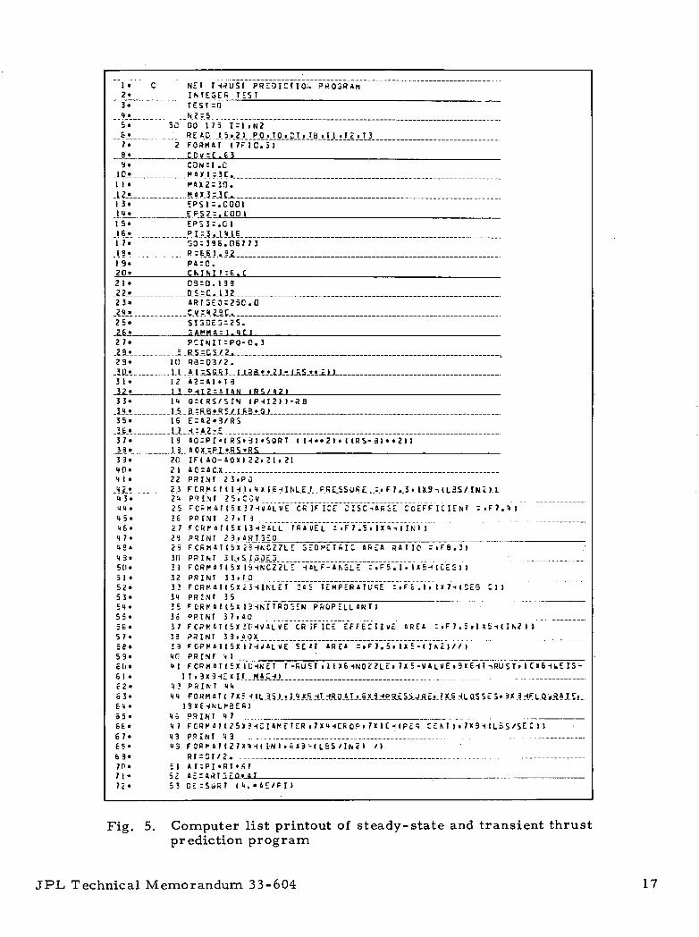
5. Computer list printout of steady-state and transientthrust prediction program 17
6. Steady-state printout: (a) MM'71 pitch/yaw,(b) MM'71 roll, (c) MM'64 pitch/yaw, (d) MM«64 roll 22
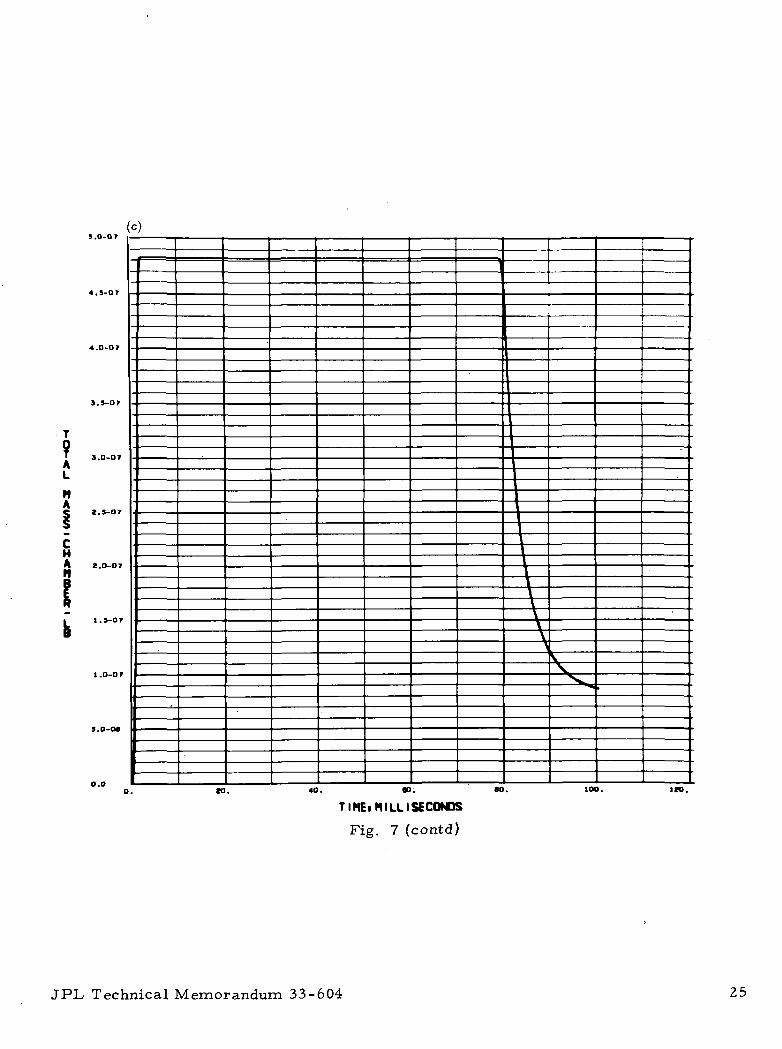
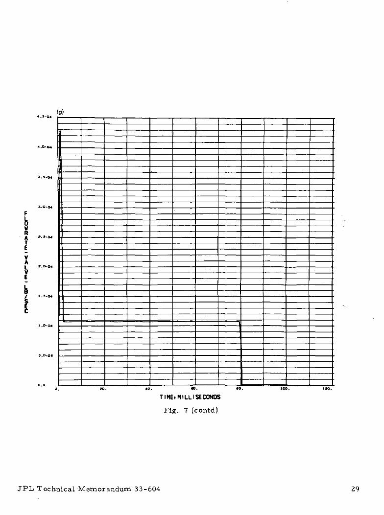
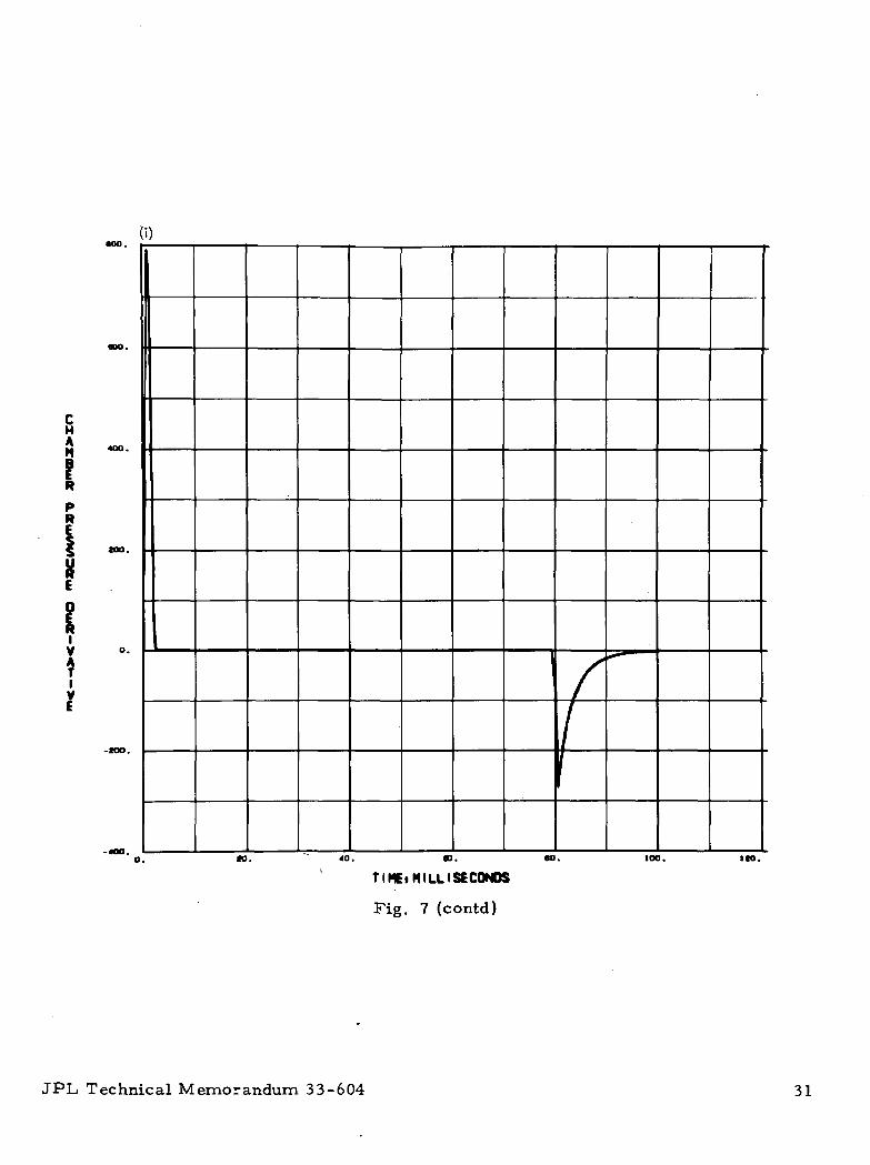
7. MM'71 pitch/yaw valve parameters as a function oftime: (a) chamber pressure, (b) total mass, nozzle,(c) total mass, chamber, (d) total mass, valve,(e) nozzle flow rate, (f) chamber flow rate, (g) valveflow rate, (h) total impulse, (i) chamber pressurederivative 23
8. MM'71 roll valve parameters as a function of time:(a) chamber pressure , (b) total mass, nozzle,(c) total mass, chamber, (d) total mass, valve,(e) nozzle flow rate, (f) chamber flow rate,(g) valve flow rate, (h) total impulse, (i) chamberpressure derivative 32
JPL, Technical Memorandum 33-604

CONTENTS (contd)
FIGURES (contd)
9. MM164 pitch/yaw valve parameters as a function oftime: (a) chamber pressure, (b) total mass, nozzle,(c) total mass, chamber, (d) total mass, valve,(e) nozzle flow rate, (f) chamber flow rate, (g) valveflow rate, (h) total impulse, (i) chamber pressurederivative 41
10. MM'64 roll valve parameters as a function of time:(a) chamber pressure, (b) total mass, nozzle,(c) total mass, chamber, (d) total mass, valve,(e) nozzle flow rate, (f) chamber flow rate, (g) valveflow rate, (h) total impulse, (i) chamber pressurederivative 50
vi JPL Technical Memorandum 33-604
ABSTRACT
The purpose of this report is to define and program the transient
pneumatic flow equations necessary to determine, for a given set of condi-
tions (geometry, pressures, temperatures, valve on time, etc. ), the total
nitrogen impulse and mass flow per pulse for the single pulsing of a
Mariner type reaction control assembly valve. The rates of opening and
closing of the valves are modeled, and electrical pulse durations of from
20 to 100 ms are investigated. In developing the transient flow analysis,
maximum use was made of the steady-state analysis undertaken in Ref. 1.
The impulse results are also compared to an equivalent "square-wave"
impulse for both the Mariner Mars 1971 (MM1 71) and Mariner Mars 1964
(MM1 64) systems. It is demonstrated that, whereas in the MM' 64 system,
the actual impulse was as much as 56% higher than an assumed impulse
(which is the product of the steady-state thrust and value on time -- i. e. ,
the square -wave), in the MM1 71 system, these two values were in error in
the same direction by only approximately 4% because of the larger nozzle
areas and shorter valve stroke used.
JPL Technical Memorandum 33-604 vii
I. INTRODUCTION
This memorandum is a supplement to Technical Report 32-1353 (Ref. 1]
and is intended to be used in conjunction with it. The work presented in that
report is limited to steady-state thrust and flow-rate determinations vs.
varying design parameters for the Mariner type ball valve/nozzle configura-
tion, in which a subsonic orifice is in series with a sonic nozzle throat
separated by a chamber volume of approximately 0.2 cm . Design variables4 5 2investigated include inlet pressures of 6. 9 x 10 to 2. 1 x 10 N/m (10 to
-4 2 -630 psi), ambient pressure of 1 x 10 N/m (1 x 10 torr) , inlet tem-
peratures of -100 to 150°C, valve orifice areas of 0.32 to 2.6 mm-4 -4 2(5 x 10 to 40 x 10 in. ), nozzle throat diameters of 0. 13 to 1.3 mm- 3 - 3
(5 x 10 to 50 x 10 in. ), nozzle geometric area ratios of 25 to 275, and
nozzle cone half-angles of 15 to 40 deg. The thrust levels considered are in
the millinewton range, and the propellant is cold nitrogen gas. The equa-
tions used to determine nozzle losses are based on flat-plate analogies.
The work described here extends the analysis and computer program
presented in Ref. 1 (using the same ranges of parameters) to include an
investigation of the transient thrust and flow-rate effects for both the
Mariner Mars 1964 and 1971 cases. Of particular concern was the total
quantity of gas consumed in the firing of each axis of the MM'71 reaction
control assembly. The results -were used in the Mariner Mars 1971 program
to aid in the flight analysis of total gas consumption, and tended to correlate
with in-flight data. The resulting Univac 1108 program can easily be
modified to investigate other valve geometries and conditions.
*The dimensions in the equations are in English units to correspond to thecomputer program on which they are based.
JPL Technical Memorandum 33-604

II. FLOW ANALYSIS
The model used to represent the MM '71 RCA jet valve is shown in
Fig. 1, where the subscripts 0, c, and N refer to conditions at the jet valve
orifice, in the plenum chamber between the jet valve orifice and nozzle,
and in the nozzle throat, respectively.
For this model, the -weight of gas in the thrust chamber W at any
time t is assumed to be given by the perfect gas law,
Wc = PcVc =
•where p is the gas density, V is the chamber volume, R is the gas constant,
T is the gas temperature, and P is the chamber pressure. For an adiabatic
process, the change in weight is proportional to the change in pressure, or
9W V 8P_ c ___ c _ c ,_.
at ~ RT at ( '
For the case to be considered in this report, at t = 0 (i. e. , imme-
diately prior to the initiation of valve opening), P_ equals the supply pres-5 2sure of 1. 0 x 10 N/m (15. 0 psia), and the chamber pressure P and
ambient pressure P equal zero (i. e. , vacuum condition). Between the timecl
the valve starts to open and the time that the chamber pressure reaches a
steady-state level (see Fig. 2), there is a difference in flow rates between
the solenoid valve orifice W_ and the nozzle W,,. This flow-rate difference
causes an accumulation of gas in the chamber, thereby building up the
chamber pressure. The differential equation of the rate of gas accumula-
tion is
dW— - w - W (3)
dt 0 N ( '
JPL Technical Memorandum 33-604

Because the local ambient is vacuum, the flow rate through the nozzle is
always sonic and is given by
J_2
N 'DN N c _ RT \y + 1
Y - I(4)
n T is the nozzle discharge coefficient, and A~, is the nozzlewhere
cross-sectional area.
The flow rate through the valve orifice W~ is sonic initially, since
P /P0 < 0. 528. During this period (0 < P /P_ < 0. 528, 0 < t < t , from
Fig. 2), the sonic orifice flow rate is given by
W, CDvVt)P0 . RT \Y + 1
(+1
(5)
where A n ( t ) is the valve orifice area as a function of time, and £-„.., is the
valve discharge coefficient. During the subsequent period, when the pres-
sure ratio P /P« is greater than 0.528 (t . <t <t 7), the flow rate throughc \j r i r £the orifice is subsonic and is given by the following equation:
RT Y - 11 -
1X 2
(6!
where a'1' is the characteristic sonic velocity (equal to /g_YRT) . At a
time t = t ?, the rate of pressure buildup in the chamber becomes zero
(i. e. , chamber pressure is constant), and the flow through the orifice equals
the flow out of the nozzle until such time t,, as the valve starts to close.
This is the steady-state thrust case and is described in detail, along with
performance losses, in Ref. 1, where
dPW = W
N 0' = 0
JPL Technical Memorandum 33-604

From the time ( t 2 ) t h e valve starts to close until the time ( to)when it is
fully closed, the flow through the valve orifice is subsonic and is given by
Eq. (6) . For t >^ t.,, the valve is fully closed (W_ = 0), and the gas accumu-
lated in the chamber is discharged by an isentropic process through the
nozzle (W = ~^n^ The density ratio for isentropic expansion is
P3(7)
where the subscript 3 refers to conditions at t = t, and p is the gas density.
Using Eq. (1) for the initial weight of gas trapped in the chamber, Eq. (7)
becomes
(8)wU N
V P. C C3" RT 1
C3Mpj
Differentiating P with respect to time, and substituting Eq. (4) and theC
equation
TC ' " ' (9)T
C3
into the results and then integrating from t_ to any time t > t_ gives the
following equation for decay pressure as a function of time:
Jl_(1 - Y) A (t - t )| 1-Y
P (t) = P |1 -^ ^-1 (10)c c3
•where A? is defined in Table 1.
JPL Technical Memorandum 33-604
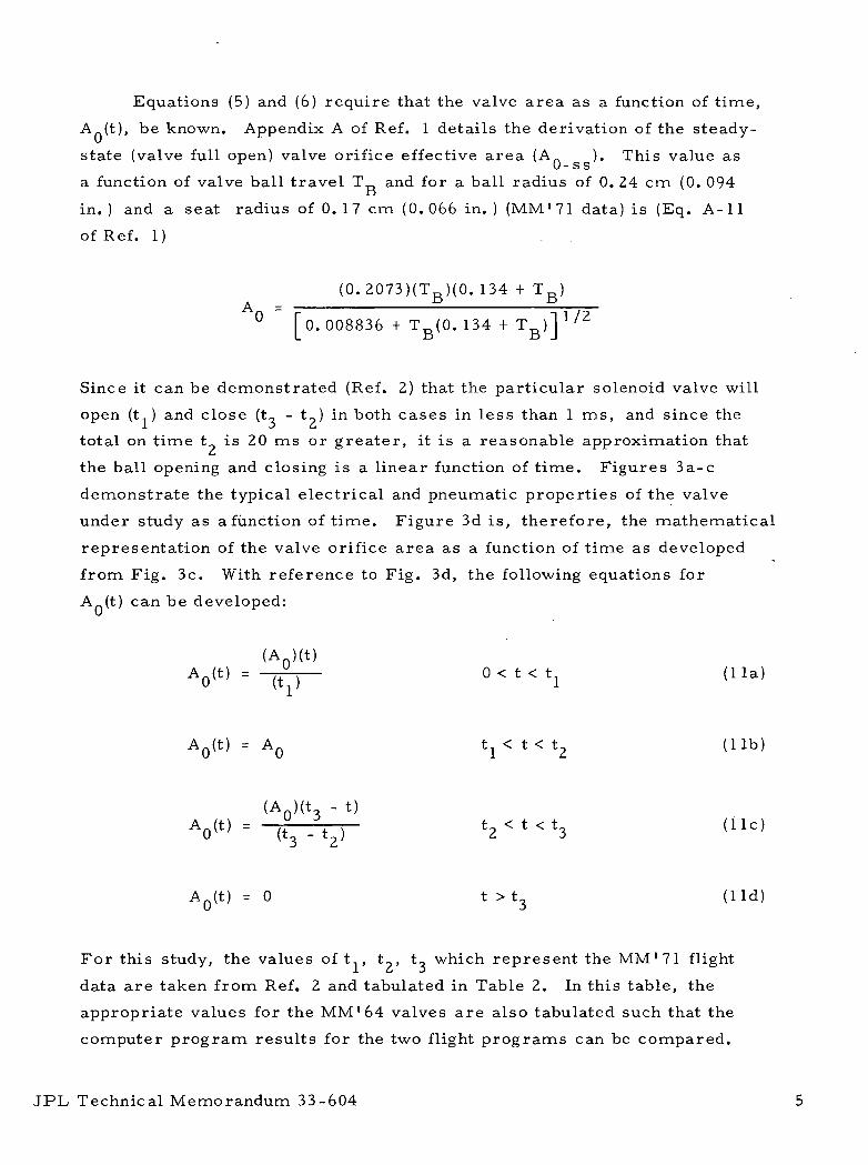
Equations (5) and (6) require that the valve area as a function of time,
A (t), be known. Appendix A of Ref. 1 details the derivation of the steady-
state (valve full open) valve orifice effective area (A_ ). This value as0- s s
a function of valve ball travel T and for a ball radius of 0. 24 cm (0. 094D
in. ) and a seat radius of 0. 17 cm (0. 066 in. ) (MM'71 data) is (Eq. A-11
of Ref. 1) .
( 0 . 2 0 7 3 ) ( T B ) ( 0 . 134
° [o. 008836 + T f i(0. 134 1/2
Since it can be demonstrated (Ref. 2) that the particular solenoid valve will
open (t ) and close (t., - t?) in both cases in less than 1 ms, and since the
total on time t is 20 ms or greater, it is a reasonable approximation thatL*
the ball opening and closing is a linear function of time. Figures 3a-c
demonstrate the typical electrical and pneumatic properties of the valve
under study as afunction of time. Figure 3d is, therefore, the mathematical
representation of the valve orifice area as a function of time as developed
from Fig. 3c. With reference to Fig. 3d, the following equations for
A (t) can be developed:
(A ) ( t )A0 ( t ) = ~liT) 0 < t < t x ( l l a )
AQ(t) = AQ tj < t < t2 ( l i b )
(A )(t - t)A0< t } = (t" - t,) t 2 < t < t 3 ( l i e )
AQ( t ) = 0 t > t 3 (Hd)
For this study, the values of t , t?, t., which represent the MM1 71 flight
data are taken from Ref. 2 and tabulated in Table 2. In this table, the
appropriate values for the MM'64 valves are also tabulated such that the
computer program results for the two flight programs can be compared.
JPL Technical Memorandum 33-604

With the value for A«( t ) thus determined, the chamber pressure P (t)
and the flow rates W (t), W _ ( t ) , and W (t) c,an be calculated using the appro-
priate equations previously defined. With the flow rates known, the accumu-
lated mass (rnn, mTvr> or rn ) is determined by solving the integral
with the appropriate flow rate equation over the appropriate time interval.
The total effective impulse I is given by the integral
1 =
t=co
(13;
where, from Ref. 1,
4-net^ipU- 1 U + 1 /
and thus,
t=00
I = K I Pc(t) dt
where
K = A tCDN(l- - losses)V -
111
The thrust losses are taken into account in Eq. (14). These losses, derived
and explained in Ref. 1, are assumed here to be a constant as a function of
JPL Technical Memorandum 33-604

time. It is also assumed that both the inlet pressure P. and the inlet
temperature T stay constant as a function of time. The actual specific
impulse I for nitrogen at ambient temperature T is
Reference 3 gives an estimated temperature profile for the entire
MM1 71 mission, including Mars occultation. If the specific impulse at any
other temperature T is desired, the following equation can be used:
However, it should be remembered that the total impulse I does not change,
since I oc V T and m oc 1 /^~T (see Eq. 15).S jp U
For the purposes of this report, an "effective" valve on time will be
defined as
e steady- state thrust
Furthermore, an equivalent "tailoff" on time, t _, will be defined as
t = At - (actual valve on time)u \J C
(17)
The use of the two time values, A, and t _, in the sizing of a gas system
for attitude control system application is explained in Ref. 2.
III. DIGITAL COMPUTER SOLUTIONS
With all the relevant equations available, a number of methods may
be used to obtain the sought after solutions. Reference 4, from which much
JPL Technical Memorandum 33-604

of the above discussion is abstracted, details a solution assuming a constant
flow density. Reference 5 describes a solution that can readily be imple-
mented on an analog computer. The solution method used in this study
involves numerical differentiation and integration programmed for a Univac
1108 computer using in part the existing program for the steady-state analy-
sis discussed in Ref. 1. The computer flowchart for the steady-state portion
of this analysis is given in Ref. 1, along with a list of nomenclature. For
the transient analysis, which is the principal concern here, the equations
previously derived must be written in the appropriate computer format for
numerical differentiation and integration. This has been done for all the
equations and is summarized in Table 1. The computer flow diagram for
the transient analysis is given in Fig. 4. The transient analysis is added
onto the end of the steady-state analysis program and is called up at state-
ment number 600 in the main program, as can be seen by the list-print
(Fig. 5). The input to the entire program is via a single read card (the
variable NZ controls the number of possible read cards) which uses a
7F10. 5 format to read in the seven variables on a single horizontal line in
Table 2. All other data, including those in Table 3, are fixed and already
in the program for this study.
In addition to the steady-state printout shown in Fig. 6, the program
is also set up to print out in tabular form, in 0. 1-ms intervals, the values
of the following variables: t, AQ(t) , Mc(t), MQ(t) , MN> Pc(t), AP/AT, I(t),
W (t), W _ ( t ) , and W (t). The program also plots out the last nine of these
variables as a function of time (see Figs. 7-10).
IV. CONCLUSIONS
Figures 7-10 show the plots for the four cases (defined in Table 2)
studied for this report. Table 4 summarizes these plots. From the table,
a number of conclusions can be drawn.
(1) On the MM' 64 pitch and yaw valves, the area ratio (ratio of
valve seat area to nozzle throat area) was 24. 5:1. As a result,
the transient flow rate for a short period of time is greater than
15 times the steady-state flow, with a 56% increase in impluse
per pulse for a nominal 20-ms valve on time.
JPL Technical Memorandum 33-604

The equivalent area ratios for the MM'71 pitch/yaw and roll
valves are 6. 24 and 2.38, respectively. With these much lower
ratios, the resulting increase in impulse per pulse is only
4 and 3%, respectively, for a nominal 79.5- and 27.3-ms value
on time. Note that the 4% figure would have increased only
slightly had the nominal on time been closer to 20 ms.
From these test points, it is concluded that for area ratios of
less than 10:1, the impulse per pulse (and gas consumed per
pulse) calculated by the much simpler steady-state approach
would be in error on the low side by less than 10%.
(2) As expected, the gas vacuum specific impulse is the same
(within 4%) when calculated by either the transient or steady-
state approach.
(3) All computer runs were made assuming a local ambient tem-
perature of 25°C. No attempt was made to determine an in-flight
ambient or gas temperature, although this could be done.
(4) The shortest electrical valve on time assumed was 20 ms.
Since pressure and flow rate build up to their steady-state value
in a short period of time (usually less than 2. 0 ms), steady-state
approximations for value times of somewhat less than 20 ms
should be valid.
(5) For this study, it was assumed that the discharge coefficients
(losses) stay constant over the relatively short transient flow
periods.
JPL Technical Memorandum 33-604

REFERENCES
1. Ferrera, J. D. , and McKown, P. M. , A Method for Calculating Steady-State Thrust and Flow-Rate Levels for Mariner IV Type Attitude ControlNitrogen Gas Jets. Technical Report 32-1353, Jet Propulsion Laboratory,Pasadena, Calif., Dec. 1, 1968.
2. Edmunds, R. S. , Investigation of the Mariner 9 Cold Gas System andAssociated Electronics (Attachment 2 to EM 344-352), EM 344-353,Jet Propulsion Laboratory, Pasadena, Calif. , July 26, 1971 (JPLinternal document).
3. Nordwall, H. , Attitude Control Jet and Acquisition Sun Sensor Temper-ature, Solar Panel Thermal Shock Test, Interoffice Memorandum,Jet Propulsion Laboratory, Pasadena, Calif. , June 24, 1969 (JPLinternal document).
4. Greer, H. , Analytical Investigation of Nitrogen Jet Reaction ControlSystems. TDR-469(5560-30)-1, Aerospace Corporation, El Segundo,Calif. , Nov. 30, 1964.
5. Bouvier, H. K. , MC-3 Altitude Control Gas Valve Performance, IOM344-390, Jet Propulsion Laboratory, Pasadena, Calif. , Feb. 2, 1965(JPL internal document).
10 JPL Technical Memorandum 33-604

tnCO
cr1
(D
O,
Soo
n)a
-sH
•
E E £ E ES S
6 S
E I 1 E | E<g A it a * it
§L-
z § z z
. i
i. ? «•
JPL Technical Memorandum 33-604 11

Table 2. Jet valve characteristics (computer input cards)
Mission
MM' 71
MM1 71
MM '64
MM '64
Axis
Pitch/yaw
Roll
Pitch/yaw
Roll
PO,N/m 2 (psi)
1.0 X 10⁵
(15)
1.0 X 10⁵
(15)
1. 0 X 105
(15)
1.0 X 10⁵
(15)
°C
25
25
25
25
mm (in. )
0.513(0. 0202)
0.831(0. 0327)
0. 290(0.0114)
0.374(0. 0147)
T
mm (in. )
0. 173(0. 0068)
0. 173(0. 0068)
0.216(0. 0085)
0. 216(0. 0085)
V sb
0. 001
0. 001
0. 001
0. 001
bV s
0.0795
0.0273
0.020C
0.020C
bto , S
0. 0805
0. 0283
0. 021C
0.021C
Nozzle throat diameter.
See Fig. 3 for definition.
Estimate.
12 JPL Technical Memorandum 33-604

Table 3. MM1 71 jet valve parameters (fixed)
Parameter Value
Nozzle discharge coefficient C,_
Valve discharge coefficient C
Ambient temperature T_, °C
Valve ball diameter, cm (in. )
Valve seat diameter, cm (in. )
Nozzle geometric area ratio
Nozzle exit geometry half-angle, deg
Ratio of specific heats (nitrogen)
Nitrogen gas constant, N-m/kg K(ft- lbf/ lbm °R)
Ambient pres sure, N/m (psi)
Valve inlet pressure P~, N/m (psi)
Valve chamber volume V_,, cm (in. )^
Time differential, s (BELT)
1. 0
0. 63
25
0.478 (0. 188)
0. 335 (0. 132)
250:1
25
1. 4
2. 967 X 102 (55. 16)
0
1. 0 X 105 (15. 0)
7. 48 X 102 (0. 0116)
0. 0001
JPL Technical Memorandum 33-604 13

CO0)SH
SnJ
Ou
rt0>
grt
P.
*!
-2> 6
d) ^M<> 4) W
+* g 0 E S0 *J
U n
< .8
m to
11 "a
-IS(I «
m. t~t
m
<L>| iml 0) X)
*3 w :^-d|3
ir5bD
to to
rt ̂^PH
S ?g a>
<U OJ4-1 -•-»
r2 £
*~"«
J* C X -Q
s|gs
0}
eii
Iflxl— z
litftiJ3 h o m "^ "~ 'U a^
*j *•* *~*
1 ItH rt C
CO
raCD
2
o o in ro
M r- ro r-
LT) ro
O^ I*- O Or— M M M
r- o m r*r\] co' ^H \oCO M rO M
,^-1 M CO O
CO CT- ^ M
O ^H sO CO
I I I I I I I Ioo oo oo oo
X X X X X X X X
CO^D roiTi rot'- T}4^-
MO MO OO OO
I I I I I I I IOO OO OO OO
X X X X X X X X
mco O^M vOt-i MinOCO Mr- I-H^H .-H!-!
*° no ^o r-o
o r- i— i ro
-
r- 1 ro i— i rn i— i co i— i ro
00 00 OO OO
X X X X X X X XCO CO 'f f̂
i-nO ^-tO MO MO
MfO MCO M-tf" (M^<
00 00 00 00
X X X X X X X Xr- co m ro
coi-i r-M into oin
— ^-i — -( —
in^H MM O^OO COMOO^D £30^D iDcO COO
co" r- M oo o' M' r-' •*'CO-" COi-H ^-t-— •-( "^
0 0 0 0
o ,j r- f̂ en '̂ .-< ̂
o o^ o o
COM -nr- o-^f T^r-•-HO roM OI-H r»^<ITtM COCO M^H COi-loo oo oo ooo' o' o" o" o' o' o' o*
-1 „.!It h it ii
?U g
S "oo
3 7S 2g !^ C** 0)0) 4->
H "m
! 1m iia mO ra
M °°
g §
2 3
o o
x S0 ^"
* m3
11 ^
h V
« jSo Th S»
0- ^*j rt
,5 (0rt ra
rt JD
14 JPL Technical Memorandum 33-604

FLOW .
VALVE NOZZLE
,/WN
1AN
VALVE CH AMBER -
Fig. 1. MM'7l jet valve model
c CHAMBER PRESSURE
Fig. 2. Typical valve chamber pressureprofile
VOLTAGETO VALVE, V
3224
1680
_ W
—-_
10 10
I I I30 / 50
(b)
TIME, s
Fig. 3. Typical valve electrical andpneumatic characteristics:(a) voltage to valve, (b) valvecoil current, (c) valvechamber pressure, (d) valveorifice area
JPL Technical Memorandum 33-604 15

YES
j 530
NO
P(N)*WC(N)WO(N)WN(N)DPDT(h
(3a)= (= (
^P(
Sa)5a)4)(2°)
N-
1
) > 0.52
r<^NO/\
WC(N) = (6b)WO(N) = (5b)WN(N) = (4)
,>*j
J
P(N) - (3b)
520
DPDT(N) =(2b)
*
*
s <
P(N) > PCSS
K =K +
).ooo5y^
. Y E
NC
5.
1
_S ^
P(N) =DPDT(SWC(N)WO(N)WN(N)
525
(3c)) = (2c)= (6c)
= (4)
P(N) =DPDT(^WC(N)WO(N)WN(N)
)/ r -. , \ YES
(30 pccc = F
= (4)̂ M = M
_
* NO.
I ,AT = T2 - T(N)
MC(N) - (9e)MO(N) - (8e)
t 550
MC(N) = (9f)MO(N) = (8f)MN(N) = (7f)l(N) = (10f)PCC(N) = (11 f)
MN(N) = (7e)PCC(N) = ( l l e )I(N) = (lOe)T(N) = T2
N =N +1
NOTE: SEE TABLE 1 FOR EQUATIONSDENOTED BY ROW NUMBERS ANDCOLUMN LETTERS IN PARENTHESES
Fig. 4. Computer program flow chart
16 JPL Technical Memorandum 33-604
1« C NET HSUSf P R E D I C T I O N P r t 0 3 f t A M2. IME3EK T E S T
'3'* T E S T E D ' "_ _ 1 * _ _ _ N 2 = 5
5. SO DO 175 1=1»N2£»_ R E A D (5.2J P_Qj_!0_!_ST. LJLt.1 1 •Jfe.'.t37» 2 F O R M A T ( 7 r f c . 3 )
_JL« CJ.1-.C..U9. C O N = I . C
_LOA M_«M ;..?£-..u*
-L2A13. ? P S I = . C Q 0 1JJL* E P S 2 : . L a O I1 5 * E P S 3 = . C 1
.ISA PJ=_i,_l1_ll17 . 5 0 = 3 9 6 . 0 6 7 7 3
ASA B_=EA.US.2.19* P»-0.2 0 . C M N I T : 6 . C21. 0 3 = 0 . 1 3 3
_22A D_SJLC..L3i2 3 . » R ( 3 £ 0 = 2 5 C . a
_2_<L*_ C.yr.H2_SC_t
25. S I3DE3=25 .26. E A M M A : 1. ilC I27 . PClN l t :PO-0 .3.23.. -i-R.S-=GS_/_2V29. 10 R 3 = 0 3 / 2 ..ill* l.L Al=JSOAJ__i-L8iL..-ZJ--JAS-«..J.lJ3 1 » 1 2 » 2 = » 1 » T 33?. 13 P-II 2 ra I»N | R ^ / » ? I3 3 * 1 M 3 = ( R S / S I N ( P H I 2 1 1 - S B.Ji«. 1.5..fl.=R.B»JlSj!.iA3_».QJ35. 16 E = » 2 « 3 / R 3
_2SA Ll_^;A.2ri:37. 19 «0 = P I * ( R S » 3 ) « S O R T ( ( H « « 2 I» I I S S - 3 ) • » 2 ) )
J_3j> 13 » O X : P I « R S . R S33. 20 IF( 4 0 - 4 0 X 1 22. 21. 21
-tfl*. 2l_»C:.»CJL4 1 . 2 2 PRINT 2 3 . P G
12 • .... 2.3 F.CRjit.llJLd-Liixlldlblut-LEfitiSilBi-JliF.Z .̂Jj-lllii.alS/JN.J J.LM3. 2U P9 INT 2 5 . C C V J _ ' 1<< i4» 25 F CKK IF <5X 3 7H«"«LVt "cfi'JF^icY""i51 s'cViR 5E~ C C E F F ICIENl = • F 7 . <* )15. ?6 P R I N T 2 7.T 3us« 2? F C R K O T I S X ms'iLU'TRVi/ET ='F~V.'sViViiViYN> )i<7. 23 P9 INT 2 9 t « R T 3 £ QU S . 2 5 F C R M » T ( 5 X Z 5 H N C Z ? L E 3 t O « E T h I C ; 4f iE» R A T I O = . F 6 . 3 )1(3. 30 P R I N T 3 1 , < S I 3 Q E 35(1. 31 F C R M S T 1 5 X I S H N O Z Z L E H » L F - » N G L t = iF 5 . 1 . I X 5H ( CE 3 ) )5 1 * 3 2 PRINT 3 3 . 1 052. 33 F C R K 1 T I 5X t S H I N L E T 3CS It MF ER & f I! 5E = • F c . I . 1 X 7 •< I DE5 C ) )5 3 « 3 M P R I N T 3 551 . 35 FORMHiX i ' 3 H N I T R O S E N P S O P L L L ' N T I5 5 « 3 6 PRINT 3 7 . A O56. 37 F O R K A U 5 X H - H V A L V E O R I F I C E E F F E C T I V E « R t * : iF 7 . : • 1 » 5 ̂ { I N2 I >5 7 « 3 3 P 3 I N T 3 3 . A O X _5E« 39 F C R K A T t 5X 1?-U*L VE S E « T »RE« = . F 7 . 5 . IX 5 - ( I N 2 > / / I59* in P R I N T '•! I ; [6ti* «1 F e R K « I I 5 ~ X ~ i t ^ N E T T -RU 5 T . I 1 X6 ̂ OZ ZL E . 7 X 5 - V ft LV E . 3 X 6 H 1 iVl} S T. I C X6 H kE IS -61* I T . 3 X 3 - K X I.T.__M*>_HJE 2 « U P R I N T I I53* 11 F O R M 4 T ( 7 X . = HJ.L3.5J.1 J.ftAS .11 HRQ.» T_i.§_X.| H_P9JuS_S-JJltj. 7 _X_S HL QS S E 3 • 3X6 1 * 1 9 X E H M P 3 E K )55. 15 PRINT '476t» 1? F C P M «I t Z S X ? - I C I * M E T E R i 7XMCf i OP« 7X I C-I ( P E 5 C E \ T ) . 7X 3 H (LB S/SE C I >67. 13 PRINT 13 .. '.68« 15 F O R M A T ( 2 7 X 1 H ( I-N) . £ X 9 - f L B S / I N 2 1 />63» RT = 3I/2,.7P* 5 I « T i P I ' R I . S T71- 52 AirAST3£fl.«-iI72. 53 DE :Sl iRT ( > i . » 4 E / P I >
Fig. 5. Computer list printout of steady-state and transient thrustprediction program
JPL Technical Memorandum 33-604 17

7 3 *7 M *7 5 *76*77 .7e*7 9 *S C *S I *9 2 *3 3 *S M *3 5 *B 6 »9 7 *5E *39.
. SC*91 *2 2 *3 3 *91*9 5 *96*3 7 *3 6 *3 3 -
i re*1C I »1 C 2 *103*iru.105*I C E *1 C 7 *i t s *I C 3 «1 1 C > «1 1 1 *1 1 2 *113*I 11.II 5*l i e *11 7.1 IS*119*I 2G*1 2 1 *1 22*1 2 3 *1 2 « *1 25 •1 26*1 2 7 *.LLS*129*
5M RE:0£/2 .5 5 S I 3 K A : ( S I 2 D E 3 / 3 6 C . I * J . * P I56 SL = I 31-« I.I. *.COi. J.SUiM.4 J7-S-La57 F 3 A r * : ( S A H ^ A * 1 . ) / ( 3 A N M A - I . )
5°. PC; PC i MI. i_ :5 5 C F C : l t 3 A M C A - l . > / 2 . > » l t « T * C O N / < A O * C D « ) > * * 2 . > « ( ( 2 . / ( 2 A M K A » l . ) ) * * F 3 A K
1 I _ _ _ .f C I K I : 1
1 I I - C F CS 3 O F O C ; ( ( | 2 . - ( ? . « 5 A q > 1 A ) l / 5 A , < H A I « ( P O « » ( t ( 2 . » 3 A M H A ) - 2 . ) / 3 A H . H A l > . ( J C « « (
2 A) I .( = C • • U_U-_l_2_,E E P C N = P C - ( F F C / C F P C I57 . IF( T £ S T ,JS.£-t-J-l,.3C-_IC_-J?.lES PRIM E-B. FPC .O rPC .PC!\ • IMS3 F Q 3 M A T 1 2X5 HFPC - , £ 1 S. 3. 5 Xe HOF PC r . El S . 3 . 5X 5 HPCN :. E 1 5 . 3 . Sx I 0-I I T£ 31
1PC ) = .14 )
T i I F ( A S S ( P C N - P C I - E F S 1 1 7 5 . 7 5 . 7 373 P C ^ P C M •_ t
7 < t I r e i > - a x l - I N l ) 7 5 . 7 5 r E l75 P * I N T 75 ,.?_£.76 F C R M A T t Z X i s u l T E R A T ION L I M I T £ X .CT t CED . 5 X 54 FC I CI V I : . £ 1 5 . 6 )77 30 TO 1.7.5 -7 8 P : - P C f.73 0£LP:?f l -PC -5C T R ; ( 3 . . T O 1 /5 . » H ? 1 .E2 ^_si WOCOT- i "o *cav " *p "o» (Tp~c"/"p"b~i"»* f F ."V S~A M~H Vi i « S S R T " ( ( 2 , * 3 o / ( s *TR)T*T34M,MA/ "
33 W T C O T = C C N * P C * A T « S 3 R T l ( 3A~MMA* GO/ ( K * T R ) ) ' « l ( 2 . / ( 3 * N H A » i . l ) • « ( 13AHM»V"11.) / ( 3 A M H O - 1 . 1 1 ) 1
3 5 A R T £ S O : . 5 * A R T 3 E O» E C N : C M M T _9 7 I N 3 : l= £ I N 2 : C _ :
33 Cl = ( j * M M A * I . )M 2.* ( 3A M M A - 1 .)>9 tl C 2 - (3 A MM A -I. 1 /2 . ; '
93 O F C N : C 3 * (2 . * C 2 * C N * CN* (- C II « ( ( 1 . • I C 2* CN* CM ) «* I - C 1- 1 . ) i« 1C 1 . » r C 2 VCN"1 * C N ) ) «*.l..7C_mj
35 C N N ^ C N - ( F C ' 4 / C F C N )36 IK2HN2* !37 I F | T £ S T ".",•<£. II 30 Tu ICO58 PRIM i S ^ F t N ^ C _ F C N I _ C N ^39 FO*N*'f('YxV^FCN" :7n 5Vr."5XS7oFCN iVtVs . 3 . 5~X 5~Vc NNi '=i Erl" 5. 9 I
ICC I F I A B S (CKN-CN; > - E F S2JI CE • 105_._1CJ1C1 CN=CNN ~
1U3 PRINT 1 0 4 . C N1 0 1 .P.CR_K A It 2.X.JL4_H T.ER.A.I-lCA.J.IitIJ..t.X.C.E.£iEJ_..5.X_S_sxt,.Uiy).. : .
30 TO 175
1C? UP : 12.; 7 C E - D 3 > « I T S » » l 3 . / 2 . » / I T i ; » 1 5 S . o l1CB RENOJ -( CM/ JO ) 'SORI (G SMMA/ t ( 3 A MM A- I . ) *C V *T f! ) I « I T
_1£.»W5A.-. J.̂ lAJ.»-LitJJly.T,B.trj.«JLii.£.l.y-lIJl«-L3in RENO = i2 . * R = ; N O U * S L « P C
«« ( ( -2 . ) /(
1 3 1 *
]J2_«-1 3 3 *L3_<i*._1 3 5 *f26_*1 3 7 *US*139*J.1.C*-1 X 1 *J_4.i_* .1 4 3 *1 4_M*.
12 IF( CN-5.5) I 13i It 3i 1 IS_L3.
1- . 3 0 3 7 5 * C N * » 2 » . 5 9 2 3 C* CN* 2 . 2 3 3 2 4 )15 SC TO -1Z3IS IF< C N - 7 . 5 1 1 1 7 . 1 1 7 . 1 1 51 ? DELSTq^LkllL.Jji^.^^A.jil13 30 TO 123IE TF I CN- S. D I I?C . I ~n. 1? ;20 Q E L S i a r O E L T « * C IC . -9*CN-38 .4 I2.1 ̂ .C._TC..JZ322 C E L S T R i O E L T«»M0.3«CN-<I1.<I I
1 2 J RE E.FFASt-rJliLSJ-R
Fig. 5 (contd)
18 JPL Technical Memorandum 33-604

115. I 2 ! < IF( R ^ - . f F n 29. I ?9i 1 25JJLL*. I?S a R I T E R i l R E - F F . R T E ' - F l / 1 K T . S T 11 < < 7 » 126 IF (43S ( AS T E 3 C - 4R ITE3 )- EPS 31 1 33. 1 3 3. 127J-1S.»,. 1 2.1 - l_F..LKAJli.--IA.3J-l.il..iJ_:LUJ.Z.L1M9. 123 IN3=IN3* I1_5C_«_ l2.i.»BJ£Bi:_L*AI£J3fl.»^AU.EJLiy.2J.^151* 1 3 C 3 C T O 3 3I =?. 1*1 PPTM n ? . t R T T F p
153. 132 F 0 3 M 4 T I 2 X 2 ' - H I T £ R 4 T I0.\ L IMIT E X C E E C t O i 5 X 1 H » S T £ 3 0 C O I V I = • £ ! = . 3)J_S!L». £C .10—U.5155. 1 3 3 S I 3 £ F F = 4 T 4 M ( R I E F . - / S L IJ.Sfc.%-- 12 !i157. 1351 5 9 « 13c C E ^ S S K T ( j C » ' S 4 " ( K 4 V K V l t " ) " "153. 1 3 7 V i = C r « C N1 cC* 1 3 S V E F H I C / 1 2 .161. 1 3 3 : F P : p ; « 4 R I T E a . 3 0 . J r / t M O S O T « ) ) £ l162. lit* FP : ( l.-Ys'.Tl . .COS ( S 13 EFF I I I / I I . «CFp )I i3» I tl F-C£L = 2. » (S i - ( . 3 | k ! A ^ - < i . ' - - l A * _ O t X ! A ^ - L l - l ' - E r - Q £ ) _ . . . . . .I£i4. 112 F M 4 X :P C» 4 T * S Q « f I I .. i4 HM4~. 34 MM4 « ( ( 2 . / ( 34 KM4 . 1 . | ) * »F5 4 H I / ( E»MI«» - U
165. 1)16b> ni C F : S G P I II (2. « 3 f t K K <• 3 4 v ! K 4 )/ C-4MM4- 1 . ) 1 .( ( 2 ./ (3 »MM4 .1 . ) ) . .F34M )«( 1167. 1- { I P i /PC l » » t ( 3 4 M H a - l . l / 3 4 M M 4 ) l ) > * ( ( P £ - P 4 ) * 4 R I I £ R / P C Ilee. I IE FTHEC 'R :CF"» "P 'C»«T169. II 7 FNr ( FM4 X -F MECJRJ./fJlAX. _1 7 0 » 1"E F L T O I : 1.-I I 1 .-FP) . ( 1 ,-FCES.I « 11 .-FM )171. 1«9 FLTOTPrFLTO_T« .LgC. , _1 7 2 * 1 5 C F N E I : F M * X . ( 1 , - F L T C I )173 . 151 PSINI 1 5 2 t F N E T . D T i 3 E L P i F L T Q I P i i n Q G O T . C N I17M. 15i F OR M 4 T ( Z X . C 1 5 . B . 7 X . F S . 5 t 5 X t F 7 . « . S X . F 6 . Z i 6 X . E TS ". S . E"X-I F E . 3 •175. PRINT 1531 7E. 153 F O R M 4 ! t InM177. IF( T EST .NE_.J_)..30_.T_0___o_CC_1 7 B « 151 P R I N T 15 5 . w"fc"o"f Vl N~2179. 155 F O R H 4 T ( 2X7 H W T O O T - . El 5. 3 . 5 X 1C -IIT ES C M£l I.miI S C * 1 5 E P R I N T 1 5 7 . f t R T E R O . 4 R I I E R .IN3191. 157 F Q 3 M 4 T I 2 X I 3.-«4i.̂ AIJ-ll!liIJ..j:tA.l5-«3.t5AlJli*i/.*J-ll.t£H ) -' £ l..;.,-3 j.5tl£LdJLti1 6 2 « 11 EL) :.I1)1 3 3 « 15* PRINT I.BO.._?..!Lt?_i_f_T!i££_!.X.EF_ _ISU. IEC F C R K 4 T . ( 2 X " n P C - i i. I E . E • 5 X H -P i = • E 1 5 . E t S X i| H I £ : •£ I 5 . E • 5 X 4-iC E :.E15.13.5» . - - . 1 .5X 5 H V £ F : . EIS. 911SE. I E 2 P R I N T t £ 3 . T R 4 T . U C . 3 E N O U . R E N O137.. . 163 FORM4Tt2X&.HlSAI--;j_£.liJ^3.iJJtJLiWiJjJJ--;jLEJ-5-».3j-S«-l.C--ia£aUil.'lua--;j-£i5^SiJJI B S * l 6 - i R £ N C : . E I 5 . e >139. 165 PSINI 1 66j.iD£LJ-4jJ2£i_SJLBj^££££I S O * 16c F C R K 4 T C 2 X ? H C E L T 4 : .E 15 .» . ?X 1 3-lD EL T 4 (S T «R I : • E 1 5 .3 . '. X 7 - REE FF :,E1191. 1 5 . 3 )I 5 2 « l c£ P P I N T 169 > r T ^ O R . F » 4 »193* 163 F O S M 4 T J1 2 M « I 7 f . P R I N T 17 1 ,FP ,FOEL .FN .r LTO I135. 1 71 F O S M 4 T 11 5E» IE 15 .5)197. 5PP Q l M g N ^ TI S E * 1 ) > . N ( 9 5 C ) . P C C l S l L M . T l S E U I i X | 5 5 C ) . r ( b 5 C ) . E f P ( 6 5 C )199. »:52 C O « P C S S = F C / P C2C1. 0£LT:O.OOai2 T 2 * T t l ) : C .2G 3 . P( 1 ) =£_,2C«. C F D T ( i ) : C .2C5« K:l2C6 . N:22H7. Z C ( 1 ) : C .2C.8« Z C ( l ) = C .2C9« ZN(1)=Q. .2 IP. E f P ( I ) :tl.211. V C ^ O . C I J5J.35.2 1 2 « , & S T 4 R : S Q R T < 3 C « ^ f l M » ' 4 . h » T R )213. 41;C3V.4SJ_t«.«iSDjiJjL2L»T/J21«4 . 4 2 : C C N « A S T 4 R . » T / ( V C « C 3 )21 5. »3:COV«4ST~4¥/Vv:>:~3l216« « » : V C / ( R » IR I
Fig. 5 (contd)
JPL Technical Memorandum 33-604 19

2 1 7 * A5 = SQ«iT (30 * 3 A M M A / ( S * T H ) I / : 32 1 J » _A_E : ( 1 . - F L I O T > « A T » S A M r ' A / I C i « S C R T I C 2 > >2 1 3 * 5DC" T I N ) r K . M - l > » C E L T2 2 C * _ _ . . . I F ( I (is I ._3_E_._T_L>__ EO _10 5C5_2 2 1 * AOT = AO* HN 177 12 2 2 « . 30 TG 5l_5 __2 2 3 * 505 I F l I ( N I . 3 1 . 1 2 1 30 1C 51C2 2 " « « A Q T i t C2 2 5 * 30 TO "Yl 52.26* 5 1C .15. IJ ( N > ._S_E.t T_2J__SO...T.Q__5_3_52 2 7 * A O T = A C * ( I . - I I ( N ) - T 2 I / ( T 3 - 1 2 ) )2 2 9 * . . . . 3 . 0 T O 5 3 02 2 3 * 5 1 5 I F ( P I N - I I . G E . P C S S ) 3 0 T O 5 2 52 3 C * _ IF ( F ( K - I ) . 5 E . C . 5 2 8 I SO TO 52 P2 3 1 * O P 3 M N I : « 3 « » O T - 4 2 . P ( N - l I2.3.2*.... . P.iN.i;-c-(KT.LL».£p_a.Li_8a*.iiE.Li2 3 3 « y C ( N ) = 4 i « * C P O T ( N I *FO231« W C ( M : 4.5 • CSV.t A.QJA F.C235* U M N l : 4 5 « C O N « 4 T « P ( N ) » P O
.2_3.e.« S_0__LC ._5.5_G2 3 7 » 5 2 0 D P D T ( N ) = 6 1 « 4 0 T • ( P ( N - 1 ) • • ( 1 . / 3 » M M « ) I . S 3 R I 1 1 . - P ( N - l ) • • ( ( 3 » M M « - 1 . ) / 3 «2.35A233*
.?J»D.«...2 i « l » I F ( P J N ) . S L . P C 5 S I 3 0 ! 0 5 2 5.2_12« WC 1M = * 1 » D P O T I I < ) « F C2 ^ 3 * W O ( N ) = C O V * 4 0 T * P O * ( P ( S I * « ( l . / 3 * M H * ) > * S 3 l ? I ( 2 . * 5 0 * 5 t M M A * ( l . - P ( N ) * * C ( 52.«t •»_•_. L&r.M»-_l_..»_/i4mi«-LJ-aA«_L8_'_2 M 5 > W M N I = 4 5 » C C N « 4 T « P ( N I « P O
.2J46... 5.C _IC^;.5_C .2 " ) 7 « 5 2 5 y C l N C C .
_<_!i«_ P. iM ^ P. C SI2 M 9 «2.5CL«...2 5 I • W O ( N ) 1 U N ( N )2 .52V 1^ lK.St...5..l_5.C..lCL.5_tl2 5 3 « K : K « 5z s u « _s_c_i_t__=5j:2 5 5 « 5 2 7 D E L T 1 : T 2 - I ( N l2.5E_« -ZCtH)_:2rtJs.-JLl2 5 7 « Z O I N ) = Z O ( N - 1 I » W O ( M » O c L T 12.5 9 « . . . _ . ZN(M:Z\(ArJLl_«_«K.(.iLl»^.EO_IJ2 5 3 « £ M P ( N I = £ M P ( N - l ) * A c > P ( N I * P O * 0 £ I . T l2 E C » P C C ( N > : P ( M « P C2 6 1 » T ( M r T 22 6 2 * 3 C T C S.5.1
26 3 • 53C OP ;3 II Nil =41 • 40 T » ( P ( N - I )«« II . / 3 A MM A) I .S33t (1 . -PI N - l ) ••( (3 A . M M 4-1. I / GA2_f *.» 1 HP A_n.- »i*AlfirJLl2 6 5 * P I N l : P ( N _ | ) , 3 p n j ( f 4 j , 3 £ L I2_66_« U C ( N I : > M « C P D T ( N l » F O2 6 7 * H 3 ( N ) = C O V * » O r * P O « ( P ( . \ l » * ( l . / 5 « . M > i l > l * S 3 , ? J ( 2 . * 3 C * 3 A M M A * ( l . - P < N I * * ( « 32.6 8 •. 1 A C M A - I . l../iAM.M_A.».J./iJl».Ta».15.A!UlA.-J^IJ-L -— --26 9 * UN I N ) = l 5 * C ON.» A T * P I N ) • PC27l>.. .3.0 T C . . 5 5 D . _
' 2 7 1 * 535 IF( H,-.F. . 1C I 3i'. TO 5J4P2 7 2 * P C C C = P I M - " i ' ) " ""2 7 3 * » i : M « i n2 7 < » * E " * C P (N ) r P C C C * ( I .-~('U-~3A> y'iV* 4~2 • I T I~N l~: VH'l / <"."»"•'<• It . »E » «!H A / ( I . - 5 A H M AT) )2 7 5 * C P C T ( . V | : ( P ( N I - P ( N - 1 ) W J £ L T2 76* AC T i c . "2 7 7 * r i C ( N I = C .2 7 3 * W M M r A 5 » ' C S " N « " A T » P I N T * P C2 7 3 * W C ( N l : - W N ( N l28ii* iFCPtNi .LE. 'bYcTdT'sb" TO lYn2 3 1 * 5 s c Z C I N I - z c ( N - i I * W C I M I . » O ; L T2 9 2 * Z C I N I : 2 0 ( K - 1 I » W C ( \ I » : £ L T233* Z N ( N l : Z N ( " w - l l _ » _ ^ N t M *0£L T2 9 < » * E K P ( M : E M K N - 1 iVilip"^ r*P"c"«"CcL i2 3 5 * P C C I N » = P(N I«_PO _ _2 6 6 * b5l P R I M ICO C .N iT(N T'^iY TTz C VN ) Vz 0 IN r«?N"(^ i. FC C IN I 16 FC T t N I • E PP ( N I • bC (2 3 7 * I N I i W U C N I t W N ( N I2 8 6 * 1 C C C > C R M » T l Y x . m i I I E 1 1. ' .I
Fig. 5 (contd)
20 JPL Technical Memorandum 33-604

299. N = N + 1~2~90~«~ " 5C I C " 5 C O291* 17M L = N-12 S 2 « DIP ENSIGN II ILL! I » > • >N »K~ETf "Tfi V N « K i t 1C > • YNt fu I 1C) tVMK2~( 1 C )•2 9 3 » l l O I » » N ' 4 K 5 l l O l t i r N 4 M 5 ( l G ) . Y . ' . i 4 M 7 < l C I ) t Y N 4 M 9 l i q i i Y N i > l 9 l l C l . ; ! O U l ( 2 l l l2 3 M « RE »L R C W 2 ( 1 )295 . DMA .11.I.L£..7.I2 9 6 « . • /297.. D.» T.»...XN_»M£_./_;2 9 B » . • /239. D A T A Y N t m /' C H 4 M 3 ~ 3ire. . •/301. D M 4 T N 4 M £ y J-fll « . L _ S .3 C 2 * . ' /30_ 3 » . „ 3 » T » ..» N.»«.«„_/! IfiJAI BASS.-£J AlitR.-Li3C1* . •/30 5 » _ C.4_T .4 TJiA.1S_/J T O T A L H 4 S S - V 4 L V E - L 33C£. " . •/307. DM4 Y N 4 M 5 _/_! fJ^OX8AIc.-fH.QZ_Zl.E.r.L3/_S.E.Csee"."" . •/30 9« 0 4 I » Y N » M S . / ' _ EkOW_8AL£.T.5J*-?13i.8.-L3-^3AS-3 1C* . •/31 1 « _ CM 4 J T N 4 M 7 /' F L O w a 4 T E - V 4 L V £ - L 3 / S £ :312." . •/3 1 3 . DM 4 r>4M3 /• _ t_a! 4L. IAPyj.S_£.rJL3__Si:_C311. . •/3 1 5 * 0414 rN 4M9._./« C_H*_M3_£S__P_S_ES_SJ_aE__0£3_lyAIJ.y.£316." . •/317. OAT A ROW I / ' '_/jTe"»"" " D 4 T 4 tii'-Ji / c . /31 9. I N I E R P r l :
3 2 0 » C C S C C J M I . L3 2 1 « . X( N) = T C N ! . « . LCCC_.3 2 2 « V I K) : P C C(M323 . . 30n. C.ON'T.I.«iy.t3 2 M . C 4 L L E Z P L C f (X ft iL i U T E R P • 11 H.E t XN« CE • » N» >• 1 •'»OK 1 .R0» 2 i C J3_25_.____ DO .9C.L.H=^tl -3 2 6 « » f ^ ) : ^ ^ ( N )3JL7.*-. . - 9f!l CONTINUE _3 2 S » C1LL E i F L C T (_X_ _'_r_ •!• •IA!J1:P • T! iLt t X N 4 J^t t V Nt|»2 • ROW 1 .f if lwr iC I329. DO 802 MfiL"33U. V IM :2 : iN )331. 3C2 CONI INOc33 j« C A L L E ? P L C T ix .Y .L I INTESP t IIILE: » x s 4 f E > Y ^ ^ . l » 3 1 ROH i t R Q » 2 t C >3 3 3 « 00 303 N = l .L3 3M. Y I N | : Z C ( N _ )3 3 5 . 303 COMINJE3 3 6 . C 'LL £ Z F L C ! (X iY iL_i I_N_!J RP 1 H Ik^ • *_Na A£ • » N * f. t • SO* 1 • RC» t• C I3 3 7 . oo act N^I .L " "3 3 B * V ( K :) : » N IN )
333. Sn^ C O N T I N U E ~"3"4C. C « L L C Z P L C T _ !.*___•_* JLl • IN 'E RP.l MJJ^E • X.N4_»<E i Y _M P S . f?OW l . R O k 5 _ i C )3t I > 00 3U5 ,M = 1 it3 < t 2 » Y ( N ) = W C ( N )313. ' J05 CONTINUE3Mt|. C 4 L L E Z P L C T (X .t »L • IN T E EP i 1 I 1 LE . X N4 f.j , Y M Kc t RQI. 1 , R Q f c ; , 0 )3 M 5 . DC 305 N:"liL3 MB. r (M i t !C(NI3« ?'» 4C£ C O N T I N U E3 t8 . C»LL E 2 F L C I (X ,< . L . IN IE SP f J I Tj.E i XN 6j<E • Y N4 c ? . ROW I . ROK 2 t 0 I3 M 9 . 00 307 N = l t L350. "^> :E.KPUJ351. 3C7 C O N T I N U E3 5 2 « C4LL E Z P L C T (X , Y_ t LiJ_N_ If_EP t.T i Tj_E.» XA^J" E L»A4f 9 • ROW 1 • RO-> 2 t C 13 5 3 * DC 903 Nrl .L3514. Y (N ) =GFO.T.(.NJ355. 303 CONTINUE '35E. C»LL EZPLCI IX tY i n I M E H P i T I I L E i X N 4 y £ t Y N a E 5 t R O K I »RQ«Z,C 1357. I 75 CONTINUE.3.5.6*. . . END
ENO OF COMP-IL 4 TIONt . N_0_ SJL»_S.NOSJ_I C.S.
Fig. 5 (contd)
JPL Technical Memorandum 33-604 21

INLET P R E S S U R E = I 5 . C C C ( L 3 S / I N 2 )V A L VE OR IFIC E G IS C H A it G E " CO'EFF I"C I ENl" Y"B A L L T R A V E L ; .ooeec UNINOZZLE G E O M E T R I C A R E A R A T l ' 6 " " = 2 5 U ~ . Q O C ~N O Z Z L E H A L F - A N S L E : 25.0 J DEJJJINLET GAS T E M P E R A T U R E - 2 5 . 0 (DE3 C)N I T R O G E N P R O P E L L A N T
.5300
VALVE ORIflCE EFFECTIVE A R E A - .00200 (IN2IV A L V E S E A T A R E A = .CIJ68 I I N 2 I
NET THRUST(L3S)
.76137258-02
NCZ2LETHR04T
DI'AME'T'ER"( I N )
. C 2 0 2 D
V A L V E_ PRESSURE
D ROP"ILflS/ IN2I
T H R U S TLOSS_ES___
(PER C E N T l
11 .19
W E I G H T_Fj.Q>!.RATE_._
( L B S / S E C I
, 1 0 6 5 2 0 3 5 - 0 3
E X I T W A C H
E . 3 7 B
INLET P R E S S U R E : l 5-o n o "-3S_/I_N2_I_V A L V E ^ O R I F I C E "DISCH»Ri3'E" CC"EFFI"CI"ENT~: "".6"2tr6"B»LL T R A V E L : .00690 (INI
• ' N O Z Z L E ' G E O M E T R I C A R E A R»iTc :" jsoVccfc ~ "NOZZLE eULFr'NSLE I Z S . O ( O E S IINLET 'GAS" fEHPERAt "uRE : " 25 .0 ( D E E ClNITROGEN P R O P E L L A N TVALVE:""b"R I FiCE " E F P E C l i v t "A R'EA "= . 7d tTfoY ~f IN'Z")V A L V E S E A T ARJH : . 01 353 (IN2I
NE f"" t hTRlFs f" "' ~~N 0^2 ZL E V A L V E T H R U S T H E I S HT E X I T M A C H• ( L B S 1 T H R O A T : F R E E S _ U R E _ __ _ L C S S E S _ F L Q W R A T E N_UJ1B_E.R
DIAMETER" " DROP IPER" CENT") ( L S S / S E C I.(I.N_I_ <_L3|j(.Il*.2_l
.1 961 S O M O - 0 1 . 0 3 2 7 0 I . Ml 95 3.83 ii.515. 'I2 7-£3 7 .085
(c) ' ~ ~~ " ' "'INLET P R E S S U R E - 1 = . C C L I L S S / I N 2 )V A L V E ORIFiCE 'Di'SCHA33'r "C"6~EF~Fi~ci"EN~ry ".630iSB A L L T R A V E L : . O O B 5 C (IN)NOz 'zLE"GEOMETRIC A R E A RYtTo'V 250.000N_czzL_E_ H A L F - A N G L E - 25 .o ICEGI .INLET GAS fEMPcRATuRE :" 25.0 ( O E 3 C)NITROGEN P R Q P E L L A K T
"v""A"LV"E"b"RIFi"CE""EFFECT"l"v"E""AR"E"A":" . QOTHTTi N2lV A L V E S E A T A R E A : • C 1 3 6 8 IIN2I
N E T ~f HR U'ST ~~Sf0 2 Z LE V A L V E T -iRUS 1 H E I G H T E X I T K A C H( L 3 S ) I J ? ? _ A T ^ P R E S S U R E _ LOSSES F_L_oy_RATE NUMBER_ _c.--_---„-. o---.- (-_----c-,^ t ^ -_ _ _ L _ S _ _ ^ _ _ _ : _ - .
( INI ( _ L 3 _ S / I N 2 I
. 2 3 7 6 1 7 3 9 - C 2 . C l l i » 0 _ .0 11 7 It. 13 .J<4 E 3 1 B tC_-^l_ t .565
INLET P R E S S U R E = i s . c c c ILBS/ INJ) •V A L V E ORIFICE D I S C H A R G E CO EFF 'lcTEN"f":""7S3'o6B A L L T R A V E L = . 0 0 6 5 0 ( IN)NOZZLE G E O M E T R I C A R E A RAT 10 "= 2507000NCZZLE_ H A L F - A N 3 L E = 25.0JPEJL!TNLET " G A S T E M P E R A T U R E ' : " 25 .0 ( O E G Cl "N I T R O G E N P P O P E L L A N T
' ORIFICE:" E F F E C T I V E AS ;E A V "Vdb"2 SO" ( I~N2T. . . . . — S E * T. *"?* "^PI3^?..i5.N21_
NET""THRUST " KTZZLE" "" V A L V E T H R U S T ' "ii'Eisn't" E X I T M A C H(LBSI T H R O A T PHESSUR_E _ L O S S _ E _ S _ _ F L O W R A T E NUMBER. _ _
D I A M E T E R bfiO"p" (PE"lT"CENf) ' it BS / 'SEC)
. X C 1 S 2 7 E 3 - 0 2 . C l < 4 ? 0 .010E 1 2 . 6 5 .5 7 32 3 6 71-C1 E . 7 1 0
Fig. 6. Steady-state printout: (a) MM'71 pitch/yaw, (b) MM«71 roll,(c) MM«64 pitch/yaw, (d) MM»64 roll
22 JPL Technical Memorandum 33-604

(a)
CHA
IR
PR
IPS
A
60. 80.
TIME,MILLISECONDS
Fig. 7. MM'71 pitch/yaw valve parameters as a function of time:(a) chamber pressure, (b) total mass, nozzle, (c) totalmass, chamber, (d) total mass, valve, (e) nozzle flowrate, (f) chamber flow rate, (g) valve flow rate, (h) totalimpulse, (i) chamber pressure derivative
JPL Technical Memorandum 33-604 23

».-06(b)
AL
MA
N0
k
40.
TIME. MILLISECONDS
Fig. 7 (contd)
24 JPL Technical Memorandum 33-604
(c)
HA
A 2.0n
!J.5-O7
*o. 4O.
TIHEiMILLISiCQNDS
Fig. 7 (contd)
JPL Technical Memorandum 33-604 25

».-06
AL
MA
A
V
60.
TIME, MILLISECONDS
Fig. 7 (contd)
too.
26 JPL Technical Memorandum 33-604

(e)
bWRA
E
60.
TIMEiMILLISECONOS
Fig. 7 (contd)
JPL Technical Memorandum 33-604 27

(f)
3.3-O4
3.O-O4
F
0 «.„
RA
- 1.3
cHA
I s.o-05
0.0
-3.0-03
60.
TIME.MILL I SECONDS
Fig. 7 (contd)
JPL Technical Memorandum 33-604
(g)
4 .0-04
J.5-O4
3.O-O4
L0URA 2. 5^O4
"*T
E
VA
yE
kB/ 1 . S-O4
rc
|
1
0. 2O. 40. CO. «0. tOO. ICO.
TIME.MILL I SECONDS
Fig. 7 (contd)
JPL. Technical Memorandum 33-604 29

(h)
• .-04
9AL
IHPU
b
•0.
T I M E . M I L L I SECONDS
Fig. 7 (contd)
30 JPL, Technical Memorandum 33-604
•00.
HAH
PR
II
1
•00.
to. 40. 60.
TI Kin ILL I SECONDS
Fig. 7 (contd)
•o.
JPL Technical Memorandum 33-604 31

15. K>. IS.
TIME, MILL I SECONDS
JO.
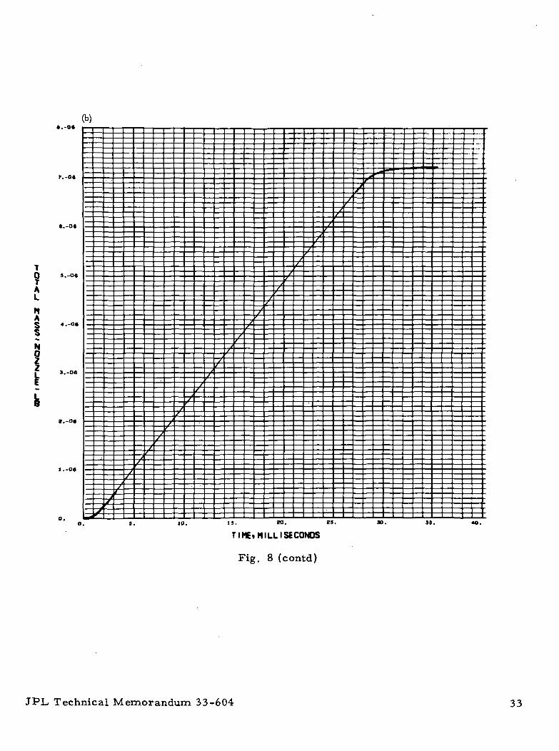
Fig. 8. MM!71 roll valve parameters as a function of time: (a) chamberpressure, (b) total mass, nozzle, (c) total mass, chamber,(d) total mass, valve, (e) nozzle flow rate, (f) chamber flowrate, (g) valve flow rate, (h) total impulse, (i) chamberpressure derivative
32 JPL Technical Memorandum 33-604
(b)
9A
HA
b
03. IS. 30. 35.
TIMEi MILLISECONDS
Fig. 8 (contd)
JPL Technical Memorandum 33-604 33

4.S-O7(c)
4.0.07
3.91.07
9AL
nA
f.S-07
HAn
b
s.Q-oa
to. is. to.**•
35. 40.
TIME, MILL I SECONDS
Fig. 8 (contd)
34 JPL. Technical Memorandum 33-604

».-oe
9AL
NA
VA
V
b
is. to. *»•
TI ME. MILL(SECONDS
Fig. 8 (contd)
3D. 39.
JPL Technical Memorandum 33-604 35

2.0-04
b
A
E
N0
L
3.O-03
0.019. W. 3D. 33. 40.
TIME. MILL I SECONDS
Fig. 8 (contd)
36 JPL Technical Memorandum 33-604

4. -04
F
bWR
HAn
5. 10. CO. 3d. IS.
TIMEi MILL(SECONDS
Fig. 8 (contd)
JPL Technical Memorandum 33-604 37

4.S-O4(g)
9.O-O4
F
0
A *-s-04
E
VA
b/ 1.3-04
I.O-O4
0. 13. K. tS.
TIME •MILLISECONDS
Fig. 8 (contd)
33.
38 JPL Technical Memorandum 33-604

5.. 04
AL
IHP 3.-O4
UL
b
S Z.-04
Ec
15. 20. IS.
TIME.MILL I SECONDS
Fig. 8 (contd)
IS.
JPL Technical Memorandum 33-604 39

HAH
pR
UR
IV
1
eoo.
40O,
200.
O.
-ZOO.
-400.
-too.13. K. if.
TIME. MILLISECONDS
Fig. 8 (contd)
JO.
40 JPL Technical Memorandum 33-604

19.(a)
CD. 3d. 40. SO.
TIME»MILLISECONDS
Fig. 9. MM'64 pitch/yaw valve parameters as a function of time:(a) chamber pressure, (b) total mass, nozzle, (c) totalmass, chamber, (d) total mass, valve, (e) nozzle flowrate, (f) chamber flow rate, (g) valve flow rate, (h) totalimpulse, (i) chamber pressure derivative
JPL Technical Memorandum 33-604 41

(b)
1,O-O«
9AL
NA
- 4.0-07
JO. 60.
TIMEi MILL I SECONDS
Fig. 9 (contd)
»0. to.
42 JPL Technical Memorandum 33-604

S.O-OT
J.O-O7AL
nA
HA Z.O-O7
3D. 40. 50.
TI ME • MILL I SECONDS
Fig. 9 (contd)
TO. »O.
JPL Technical Memorandum 33-604 43

AL
HA
VAL
40. SO.
TIME • MILL I SECONDS
Fig. 9 (contd)
jo. ao.
44 JPL Technical Memorandum 33-604

(e)
F
bWP Z.O-Q3
A
E
H
4 1.5-O5
L
SO. 40.
T I M E i M I L L I SECONDS
Fig. 9 (contd)
f- -t T »
ao. M>.
JPL, Technical Memorandum 33-604 45

• .-04
bwRA
E
CHAn
b
10. to. 30. 40. so. go. jo. »o.
TIME.MILLISECONDS
Fig. 9 (contd)
46 JPL, Technical Memorandum 33-604

(9)
b
VA
/ Z.-04
a. 10. to. Jo. 40. so. ao.
TIME, MILL I SECONDS
Fig. 9 (contd)
JPL Technical Memorandum 33-604 47

(h)
7.-QS
AL
Inpu
4. -05
3.-OS
s
I.-OS
30. 40. 30. 60. TO. ra.
TIME*MILL I SECONDS
Fig. 9 (contd)
48 JPL, Technical Memorandum 33-604

HAn
pR
0
I
V
TIME, MILLISECONDS
Fig. 9 (contd)
JPL Technical Memorandum 33-604 49

(a);
- f t
HAn
pR
PS
tO. 30. 40.
TIME. MILL I SECONDS
LLTO.
Fig. 10. MM'64 roll valve parameters as a function of time: (a) chamberpressure, (b) total mass, nozzle, (c) total mass, chamber,(d\ total mass, valve, (e) nozzle flow rate, (f) chamber flowrate, (g) valve flow rate, (h) total impulse, (i) chamberpressure derivative
50 JPL, Technical Memorandum 33-604

(b)
AL
HA
M
f ».0-OT
l.O-OT
0.0 tO. 30. 40.
TI ME. MILL I SECONDS
Fig. 10 (contd)
JPL Technical Memorandum 33-604 51

30. 40.
TIME.MILL I SECONDS
Fig. 10 (contd)
52 JPL Technical Memorandum 33-604

t .4-06
T
AL
nA
syA
o.o
11
/
1
/1
1
1t
1t
1f111
1f
f
11
f' •
' i
i ! i
1
i
i
i
;i
i
I
i!
j
1i
\
30. 40.
TIME*MILL I SECONDS
Fig. 10 (contd)
JPL Technical Memorandum 33-604 53

b8A
E
.,.., t.«-.-(-t • + • •
tO. 30. 40.
TIMEtMILLISECONDS
Fig. 10 (contd)
54 JPL Technical Memorandum 33-604

bA
E
HAHB
R
r
10. 40.
TIME. MILLISECONDS
Fig. 10 (contd)
-i *
JPL Technical Memorandum 33-604 55

buRA
_
VA
.-04(g)
5.-04
*.-<M
J.-04
+4-
W. SO. 40.
TIME. MILL I SECONDS
Fig. 10 (contd)
so. •o.
56 JPL Technical Memorandum 33-604

(h)
1.0-04
•,0-OS
9KL
•.0-09
0.0JO, 40.
TI Ml. M I L L I SECONDS
Fig. 10 (contd)
JPL, Technical Memorandum 33-604 57

»MO.
HAH
IPR
jf
IVA
1QOO.
10. 40.
TIME. MILL I SECONDS
so.
Fig. 10 (contd)
58 JPL Technical Memorandum 33-604NASA — JPl — Coml., L.A., Calif.