a method for comparative analysis of trusted execution
TRANSCRIPT
Portland State University Portland State University
PDXScholar PDXScholar
Dissertations and Theses Dissertations and Theses
6-8-2021
A Method for Comparative Analysis of Trusted A Method for Comparative Analysis of Trusted
Execution Environments Execution Environments
Stephano Cetola Portland State University
Follow this and additional works at: https://pdxscholar.library.pdx.edu/open_access_etds
Part of the Computer Engineering Commons, and the Information Security Commons
Let us know how access to this document benefits you.
Recommended Citation Recommended Citation Cetola, Stephano, "A Method for Comparative Analysis of Trusted Execution Environments" (2021). Dissertations and Theses. Paper 5720. https://doi.org/10.15760/etd.7593
This Thesis is brought to you for free and open access. It has been accepted for inclusion in Dissertations and Theses by an authorized administrator of PDXScholar. Please contact us if we can make this document more accessible: [email protected].
A Method for Comparative Analysis of Trusted Execution Environments
by
Stephano Cetola
A thesis submitted in partial fulfillment of therequirements for the degree of
Master of Sciencein
Electrical and Computer Engineering
Thesis Committee:John M. Acken, Chair
Roy KravitzTom Schubert
Portland State University2021
© 2021 Stephano Cetola
This work is licensed under a Creative Commons “Attribution 4.0 International”
license.
Abstract
The problem of secure remote computation has become a serious concern of
hardware manufacturers and software developers alike. Trusted Execution Envi-
ronments (TEEs) are a solution to the problem of secure remote computation in
applications ranging from “chip and pin” financial transactions [40] to intellectual
property protection in modern gaming systems [17]. While extensive literature has
been published about many of these technologies, there exists no current model
for comparing TEEs. This thesis provides hardware architects and designers with
a set of tools for comparing TEEs. I do so by examining several properties of a
TEE and comparing their implementations in several technologies. I found that
several features can be detailed out into multiple sub-feature sets, which can be
used in comparisons. The intent is that choosing between different technologies
can be done in a rigorous way, taking into account the current features available
to TEEs.
i

Dedication
To my wife Dana, my daughter Kristy, and my son Chad.
For all their love and support.
ii
Acknowledgments
I would like to thank my thesis committee, John M. Acken, Roy Kravitz, and Tom
Schubert, for their guidance in writing and refining this work, as well as for their
classes which helped to inspire my journey.
For their patience in teaching me the intricacies of that arcane art known as
firmware, I thank Brian Richardson, Mike Kinney, and Vincent Zimmer.
For explaining countless complex computational subjects, inadvertently helping
me chose a thesis topic, and for answering my endless stream of questions over the
course of many sushi dinners, I thank Brian Avery.
And my thanks to Mike Lestik, who first introduced me to Plato’s Euthyphro and
Newton’s Calculus, and has been a lifelong friend.
iii

Contents
Abstract i
Dedication ii
Acknowledgments iii
List of Tables vi
List of Figures vii
Glossary viii
Acronyms x
1 Introduction 1
2 Background 5
2.1 Overview . . . . . . . . . . . . . . . . . . . . . . . . . . . . . . . . . 5
2.2 The Predecessors of the TEE . . . . . . . . . . . . . . . . . . . . . 5
2.3 Birth of a TEE . . . . . . . . . . . . . . . . . . . . . . . . . . . . . 8
2.4 From Handsets to the Cloud . . . . . . . . . . . . . . . . . . . . . . 13
2.5 RISC-V: An Open Source TEE . . . . . . . . . . . . . . . . . . . . 14
3 Intel Software Guard Extensions 17
3.1 The Intel SGX Solution . . . . . . . . . . . . . . . . . . . . . . . . 17
3.2 Initial SGX Enclave Setup . . . . . . . . . . . . . . . . . . . . . . . 17
3.3 Executing SGX Enclave Code . . . . . . . . . . . . . . . . . . . . . 19
iv

3.4 Life Cycle of an SGX Enclave . . . . . . . . . . . . . . . . . . . . . 21
3.5 Attestation with Intel SGX . . . . . . . . . . . . . . . . . . . . . . 23
4 Arm TrustZone 27
4.1 The Arm TrustZone Solution . . . . . . . . . . . . . . . . . . . . . 27
4.2 Arm Trusted Firmware . . . . . . . . . . . . . . . . . . . . . . . . . 31
4.3 TrustZone Attestation . . . . . . . . . . . . . . . . . . . . . . . . . 34
5 RISC-V Physical Memory Protection 40
5.1 The RISC-V Open Source ISA . . . . . . . . . . . . . . . . . . . . . 40
5.2 The RISC-V Memory Model . . . . . . . . . . . . . . . . . . . . . . 42
5.3 RISC-V Physical Memory Attributes . . . . . . . . . . . . . . . . . 44
5.4 RISC-V Physical Memory Protection . . . . . . . . . . . . . . . . . 46
5.5 Keystone Enclave . . . . . . . . . . . . . . . . . . . . . . . . . . . . 49
5.6 Future Extensions of RISC-V Memory Protection . . . . . . . . . . 53
6 Trusted Execution Environment Comparisons 55
6.1 A Method for Comparing TEEs . . . . . . . . . . . . . . . . . . . . 55
6.2 Mapping Data Points . . . . . . . . . . . . . . . . . . . . . . . . . . 59
6.3 Considerations and Limitations . . . . . . . . . . . . . . . . . . . . 64
7 Conclusion 65
References 67
v
List of Tables
2.1 OMTP Threat Groups . . . . . . . . . . . . . . . . . . . . . . . . . 11
4.1 Arm Privilege Level Mapping . . . . . . . . . . . . . . . . . . . . . 31
5.1 RISC-V Atomic Instructions for I/O . . . . . . . . . . . . . . . . . 45
5.2 RISC-V Processor Modes . . . . . . . . . . . . . . . . . . . . . . . . 46
6.1 TEE Features and their dependencies . . . . . . . . . . . . . . . . . 61
6.2 Attestation Comparison . . . . . . . . . . . . . . . . . . . . . . . . 62
6.3 Extensibility Comparison . . . . . . . . . . . . . . . . . . . . . . . . 63
vi
List of Figures
1.1 Protection Rings . . . . . . . . . . . . . . . . . . . . . . . . . . . . 2
2.1 GlobalPlatforms Typical Chipset Architecture . . . . . . . . . . . . 12
2.2 Hardware Security Timeline . . . . . . . . . . . . . . . . . . . . . . 16
3.1 High Level SGX Overview . . . . . . . . . . . . . . . . . . . . . . . 18
3.2 Setting Up Intel SGX . . . . . . . . . . . . . . . . . . . . . . . . . . 19
3.3 Intel SGX Enclave Lifecycle . . . . . . . . . . . . . . . . . . . . . . 21
3.4 Intel SGX Attestation . . . . . . . . . . . . . . . . . . . . . . . . . 25
4.1 High Level TrustZone Overview . . . . . . . . . . . . . . . . . . . . 28
4.2 High Level Overview of Trusted Board Boot . . . . . . . . . . . . . 32
4.3 TrustZone Example of Normal and Secure World . . . . . . . . . . 34
4.4 Detail of Trusted Firmware Trusted Board Boot . . . . . . . . . . . 36
4.5 OP-TEE Chain of Trust . . . . . . . . . . . . . . . . . . . . . . . . 38
5.1 RISC-V 32 bit PMP CSR Layout and Format . . . . . . . . . . . . 47
5.2 High Level RISC-V PMP Overview . . . . . . . . . . . . . . . . . . 49
5.3 Keystone System Overview . . . . . . . . . . . . . . . . . . . . . . . 50
5.4 Keystone PMP Protection . . . . . . . . . . . . . . . . . . . . . . . 51
vii
Glossary
attestation The process of assuring the validity and security of a system. The
system can only be valid and secure if the code and data stored on the system
have not been altered in any way that either causes the system to operate
outside specifications or compromises the trust model. 4, 11, 14, 17, 21–25,
34, 39, 55–60, 64
axiomatic A semantic of logic which formalizes the definition of a concept using
a set of criteria or axioms, all of which must be true for the given definition
to be met. 43
chain of trust A series of entities that engage in secure transactions in order to
provide a service. The first entity in the chain is referred to as the root of
trust, while the last entity in the chain is often the end user or application
requiring a secure transaction. 9, 32, 37, 38
cryptographic hash A cryptographic hash is the result of a mathematical func-
tion whose input is data of variable length and whose output is data of a
deterministic value and fixed length. If this hash represents a piece of soft-
ware, we can consider this hash the software’s “identity” [9] for purposes of
attestation. Many systems of attestation refer to this hash as a “measure-
ment”. 19, 22, 24, 34, 57
hart In a RISC-V system, a core contains an independent instruction fetch unit
and each core can have multiple hardware threads. These hardware threads
are referred to as harts. 42, 43viii
operational semantic A semantic of logic which formalizes the definition of a
concept by generating a golden output model. Any system meeting the
definition must produce the same output as that defined in the model. 43
privilege ring Also known as a “protection ring” or “protection domain” [33],
these modes of operation allow a processor to restrict access to memory or
special instructions. Switching between rings is the function of low-level
software or firmware. Before the problem of secure remote computation
described in Chapter 1, these rings provided adequate protection for software
applications. 1, 5, 7, 8, 19, 21–23, 30
Root of Trust “A computing engine, code, and possibly data, all co-located on
the same platform which provides security services. No ancestor entity is
able to provide trustworthy attestation for the initial code and data state of
the Root of Trust” [25]. For system security purposes one might say, “the
buck stops here”. xi, 11, 17, 35, 53, 57
Trusted Compute Base When referenced generally, the code which must be
trusted in order for the system to be considered secure. The code can include
platform firmware, firmware from the manufacturer, or any code running
inside the TEE. When in reference to a specific application, the TCB may
only refer to the part of the application which runs inside the TCB. xii, 17,
57
ix
Acronyms
AEX Asynchronous Enclave Exit. 20
AMBA Advanced Microcontroller Bus Architecture. 28
AMO atomic memory operation. 44, 45
AXI Advanced eXtensible Interface. 28
DMA Direct Memory Access. 6, 11, 17, 54
EFI Extensible Firmware Interface. 6, 7
EPC Enclave Page Cache. 18–20, 22, 23
EPID Enhanced Privacy ID. 24, 25
ePMP Extended Physical Memory Protection. 15, 16, 53, 54
Intel ME Intel Management Engine. 6, 8, 16
IOPMP I/O Physical Memory Protection. 15, 16, 54
MSR model-specific register. 17
NMI non-maskable interrupt. 5
OMTP Open Mobile Terminal Platform. 10–12, 16
OP-TEE Open-source Portable TEE. 26, 27, 35, 37, 38, 60
x
OTP One Time Programmable. 32
PCMD Paging Crypto MetaData. 23
PMA Physical Memory Attributes. 14, 44–46
PMP Physical Memory Protection. 2–4, 14–16, 39, 41, 42, 46–50, 53–55, 62, 65,
66
PRM Processor Reserved Memory. 17–19
REE Rich Execution Environment. 13, 37
RISC reduced instruction set computer. 40
RoT Root of Trust. 11, 17, 35, 36, 53, 57, 58, 62
ROTPK Root of Trust Public Key Hash. 32, 33
RVWMO RISC-V Weak Memory Order. 42–45
SCR Secure Configuration Register. 27, 29
SECS SGX Enclave Control Structure. 22
SEV Secure Encrypted Virtualization. 13
SGX Software Guard Extensions. 2–4, 8, 13–17, 19, 20, 23–28, 48, 55, 57, 60, 64
SMC Secure Monitor Call. 29, 37
SMI System Management Interrupt. 5, 6
SMM System Management Mode. 5–7, 16, 17
xi
SMRAM System Management RAM. 6, 7
SoC System on Chip. 11, 13, 16, 27–29, 32, 34
sPMP S-Mode Physical Memory Protection. 15, 16, 53, 54
SSA State Save Area. 20, 21
TA Trusted Application. 11, 37, 38
TBB Trusted Board Boot. 32, 33, 36
TCB Trusted Compute Base. 17, 24, 57, 58
TCG Trusted Computing Group. 9
TCS Thread Control Structure. 20
TEE Trusted Execution Environment. i, ix, 1–16, 23, 26, 28, 30, 32, 34, 37–39,
48–50, 52–66
TF-A Trusted Firmware-A. 26, 27, 31, 33, 35, 36, 38, 60
TLB Translation Lookaside Buffer. 44
TPM Trusted Platform Module. 8, 9, 12, 15–17, 38
TXT Trusted Execution Technology. 17
TZASC TrustZone Address Space Controller. 29
TZMA TrustZone Memory Adapter. 29
UEFI Unified Extensible Firmware Interface. 6, 18, 19, 33, 35
xii
VA Version Array. 23
VMS Virtual Machine Extension. 7
VT-x Intel Virtualization Technology. 7, 16
xiii
Chapter 1
Introduction
Historically, computer architecture security relied on processor modes or privilege
modes where code was allowed to execute. In these modes, separation of privileges
is achieved and often referred to as “rings” with “ring 0” being the most privileged
machine mode where OS kernel code runs and privilege ring 3 being the least
privileged user mode where application code runs. Figure 1.1 shows this concept
and we will briefly discuss how it is applied to different architectures in the coming
chapters.
As applications became more complex, specifically with the advent of large-
scale virtualization and the internet, this simple security model broke down as
executed code could no longer be trusted, nor its origin verified. The problem
of “secure remote computation” arises where the data owner must trust not only
the software provider, but also the remote computer and infrastructure on which
that software is executed. Homomorphic encryption solves the problem of secure
remote computation to some extent, however the performance overhead of this
transaction limits its application [22].
In an attempt to address the problem of secure remote computation, micropro-
cessor designers have implemented different types of Trusted Execution Environ-
ments (TEEs), first defined by the Open Mobile Terminal Platform and ratified
in 2009 [45]. These TEEs are intended to allow for code and data to reside in a
specially provisioned area of memory where the processor can reserve access rights
using a given set of rules. The processor will then guarantee the confidentiality
1

Ring 3
Ring 2
Ring 1
Ring 0
Kernel
Device Drivers
Device Drivers
Applications
Least Privileged
Most Privileged
Figure 1.1: Hierarchical protection domains or protection rings. Processorswill define the method for switching between modes in such a way that code runningin “ring 3” should not have access to code or data running in the rings below it.Attempts to access memory or to run special privileged instructions should throwan exception. Device drivers may run at a higher privilege level to gain access tospecial instructions. Figure recreated from Hertzsprung at English Wikipedia, CCBY-SA 3.0, via Wikimedia Commons.
and integrity of that region of memory based on the configuration of the system.
In choosing a TEE, hardware architects have many complex features to consider
before picking a platform. Currently, many resources exist that cover the features
and design details of specific TEEs, however there are few resources that combine
this information into one source for comparison. In this thesis, we will examine
Intel Software Guard Extensions (SGX), Arm TrustZone, and RISC-V Physical
Memory Protection (PMP) in order to provide a methodology for comparing and
evaluating TEEs by considering these technologies’ respective strengths and weak-
nesses. The goal of this thesis is not to characterize one technology as overall
superior to another, nor is the goal to expose fatal flaws that make one technology
2
inherently insecure. Rather, we will describe the properties of a hardware TEE
and illustrate how each technology implements those properties. A comparison
of these different implementation details yields a method of evaluating TEEs for
those looking to choose the TEE that best fits their needs.
These three technologies were chosen for specific reasons. Intel SGX is available
on most consumer desktop/laptop products, and the technology is now becoming
popular on their Xeon line of server/workstation processors. Arm is the de facto
architecture used in cell phones and embedded devices. The popularity of these two
architectures makes them a natural choice for comparison. The third technology,
RISC-V PMP, is a newcomer to the stage of TEE options. We will examine how the
more mature technologies have informed choices made by the architects of RISC-
V, as they are clearly addressing specific limitations with current technologies.
While the method used to examine these technologies will be restricted to those
aforementioned three TEEs, this method can be applied to any TEE.
The goal of this thesis is to provide hardware implementers with a method for
comparative analysis and not to act as a definitive guide to any one of these three
technologies. Any hardware implementation details are given only as examples and
are not intended to be used in production systems. Furthermore, this thesis is an
examination of the hardware and not the many possible software implementations
available. As such, while we may discuss firmware and software throughout the
thesis, it is not meant to be a guide to properly implementing a complete solution.
This thesis will begin by giving a brief history of TEEs as well as some of the
cryptographic underpinnings of the technology (chapter 2). In considering these
topics, we will provide definitions for many of the technologies used in a TEE
in order to constrain ourselves to hardware implementations only. We will then
3
give a detailed analysis of Intel SGX (chapter 3), Arm TrustZone (chapter 4),
and RISC-V PMP (chapter 5). We will examine how these technologies provide
the fundamental properties of a hardware TEE: code integrity, data integrity, and
data confidentiality. Furthermore, we will describe how some of these solutions can
provide more advanced features like code confidentiality, authenticated launch, pro-
grammability, attestation, and recoverability. Lastly we will provide a comparison
of the three technologies and their methods for providing the fundamental and
advanced properties of a hardware TEE (chapter 6).
4
Chapter 2
Background
2.1 Overview
In order to understand Trusted Execution Environments (TEEs) we must first look
at how computer architecture security worked before the problem of secure remote
computation. The processor modes discussed in the introduction contained four
privilege rings with the most privileged level, privilege ring 0, executing operating
system kernel code. However, in most modern x86 client systems there are 3 levels
of even greater privilege than privilege ring 0. We will examine each of these briefly
and describe why they do not provide the same type of protections that a TEE
provides.
2.2 The Predecessors of the TEE
In 1990, Intel integrated a new privilege mode into their i386SL processor called
System Management Mode (SMM) [67], now commonly referred to as “privilege
ring -2” (privilege ring negative two). OS code does not have access to this privilege
level and only specific firmware, usually provided by the platform manufacturer, is
allowed to execute code in SMM. This processor mode is entered by using a special
System Management Interrupt (SMI). This interrupt has the highest priority of
any interrupt as of the writing of this thesis, and is even higher priority than a
non-maskable interrupt (NMI). Common tasks one might perform in SMM include
thermal management, power management, or even something as simple as alter-
ing the volume output in response to buttons on a laptop keyboard [66]. SMM
5
would remain the most privileged level of code execution until the release of Intel
Management Engine (Intel ME) in 2008 [19].
The memory used in SMM, called System Management RAM (SMRAM), is
secured from any accesses or modifications originating anywhere outside SMM.
Secured accesses include any accesses or modifications originating from the CPU,
from I/O devices, and from Direct Memory Accesses (DMAs). When an SMI is
generated, all the CPU threads enter SMM and each of their register states are
saved in a memory table inside SMRAM. Work can now be done by the SMI
handler. Once this work is finished, each of the CPUs previous states are restored
and execution is handed back to where the SMI was originally generated. Since
there can be multiple SMI handlers there is firmware code that runs in a single
thread and acts as an SMI dispatcher. All other CPU threads wait inside SMM
until the handler thread has returned [18]. This firmware code is an implementation
of the Unified Extensible Firmware Interface (UEFI) specification, which is the
successor to the Extensible Firmware Interface (EFI) specification [68].
There are several reasons why SMM is not a suitable replacement for a TEE.
Firstly, using SMM for any tasks which consume a significant amount of time
would cause the system to hang while SMIs are handled. As such, SMM tasks are
confined to small workloads which can return quickly and do not need to happen in
rapid succession. However, tasks which take significant amounts of time and may
occur in rapid succession are exactly the types of tasks we wish to run in a TEE.
Tasks like processing a credit card payment, or verifying the identity of the user
with biometrics would all take significant time to run and would need to happen
in quick succession.
Secondly, SMM is very restrictive in terms of how code is developed for the
6
platform. All code executed in SMM must be located inside the system firmware,
loaded into SMRAM, and locked before the OS is loaded into memory. As such,
firmware code does not have easy access to communicating with the host OS but
must use special EFI SMM variables [60].
Lastly, while updating firmware in the field is possible [69], it almost always
requires a reboot of the system. Updating the code in a TEE is a critical function
that will be required much more often than a firmware update and should not
require system reboot each time. These are just a few reasons why SMM is not
a suitable solution to the problem of secure remote computation. Perhaps the
overarching reason is that SMM was not designed to solve the problem of secure
remote computation. Regardless, we have shown why it should not be used where
a TEE would be better suited.
In 2005 [61], Intel released their first processor to allow the next most privileged
mode of their x86 processors, Intel Virtualization Technology (VT-x)1. Commonly
referred to as “privilege ring -1” (ring negative one), VT-x added new instructions
called Virtual Machine Extensions (VMSs). These instructions are used to create a
layer of hardware isolation between the host OS from the guest OS. It is tempting
to see a TEE as a type of virtualization. Indeed, one early form of a trusted
computing environment used a “dedicated closed virtual machine” [21] to achieve
many of the goals of a modern TEE. However, as others have shown [54], this type
of virtualization fails to cover several key properties of a TEE. For our purposes,
we will consider these properties attestability and code confidentiality, and will
discuss these in depth in coming chapters.
1We use the acronym VT-x here to refer to all of Intel Virtualization Technologies, though inthis case the “x” refers to Xeon processors with this feature. Non-Xeon processors would use thedesignation VT. There is also Intel Virtualization Technology for Directed I/O (VT-d). In thisthesis we will use VT-x so as to avoid any confusion with the common acronym VT.
7
In 2008 [19], Intel developed what is today the most privileged processor level
on x86 hardware, the Intel Management Engine (Intel ME). This technology, com-
monly referred to as “privilege ring -3” (privilege ring negative three) is not actually
a processor mode at all. It is instead a feature of some Intel chipsets. Most of the
properties of Intel ME are obscured by the proprietary firmware that it runs. The
majority of information available regarding Intel ME is found either in Intel’s pub-
lications or from the plethora of reverse engineering done by security researchers.
As such, we will not consider Intel ME a suitable replacement for a TEE for two
key reasons: most of the information about this technology is gained by indirect
means like reverse engineering and the firmware is not intended to be modified
from the signed binary provided by Intel.
These three x86 “negative privilege rings” provide hardware protection of vari-
ous kinds and each has its own restricted area of memory. However, none of these
technologies serve as a viable solution to the problem of secure remote computa-
tion. It is no surprise that Intel eventually developed Software Guard Extensions
(SGX), their own implementation of a TEE in order to address this problem. Be-
fore we address SGX specifically, we will continue to track the development of
Trusted Execution Environments (TEEs) by starting with their use in handsets,
the precursor to today’s smartphones.
2.3 Birth of a TEE
The concept of securing computation is not a new idea. As we have seen with
Intel ME, neither is the technique of using a processor other than the main, gen-
eral purpose CPU for secure computation. For almost two decades [47] hardware
manufacturers have relied on Trusted Platform Modules (TPMs) for a similar kind
8
of secure computation. In 2009 the Trusted Computing Group (TCG) specifica-
tion for a TPM was ratified as an ISO standard. A TPM is a system that must
remain separate from the system it reports to: the host system. It can be a single
physical component that communicates with the host system over a simple bus.
TPMs can have their own processor, RAM, ROM, and flash memory. While the
host system cannot directly change the values of the TPM memory, it can use the
simple bus to send and receive information. As of TPM version 2.0, the TPM
can now be a part of the main processor, however it must use hardware memory
partitioning and use a well defined interface instead of the simple bus. The use of
the main processor as a TPM may add significantly more speed, but at the cost
of more complexity. TPMs contain random number generators, cryptography key
generators, and secure storage.
While TPMs have many of the features we require of our TEEs, they were
designed with securing small amounts of data like cryptographic keys, not entire
applications. TPMs focus on security over speed and their cryptographic algo-
rithms may be purposely run at much slower speeds than is possible with a CPU,
let alone a cryptographic accelerator. TPMs do, however, provide a valuable tool
for a TEE to use as part of its chain of trust2. Concepts used in a TPM like
secure storage and isolated memory are expanded in a TEE with concepts like
isolated and protected IO and isolated RAM. It is not surprising that we see the
first industry efforts around TEEs around the same time that the ISO standard
for TPMs is published.
2Unsurprisingly, the concept of a “chain of trust” comes out of electronic commerce securitypublications from the 1990’s [40]. The internet opened up the concept of electronic commerce toa much broader audience. In doing so, it also opened up a much larger attack surface for threatmodels to consider.
9
TEEs were first defined by the Open Mobile Terminal Platform (OMTP) Hard-
ware Working Group and ratified in 2009 [45]. This standard was designed specif-
ically for “handset manufacturers”. The OMTP standard was transferred to the
Wholesale Applications Community (WAC) in 2010 and in July 2012 WAC itself
was closed, with the OMTP standards being transferred to The GSM Associa-
tion (originally Groupe Special Mobile) [48]. The OMTP standard defines an
“execution environment” as a combination of five elements: a processing unit, a
bus, physical memory, a boot process, and the contents of the execution environ-
ment [45]. These contents include the code, data, and keys required for computa-
tion. The OMTP document goes on to describe two sets of security requirements
which meet their definition of a TEE, called “Profile 1 and 2”. Profile 2 provides
greater security than Profile 1, however both meet their definition of a TEE.
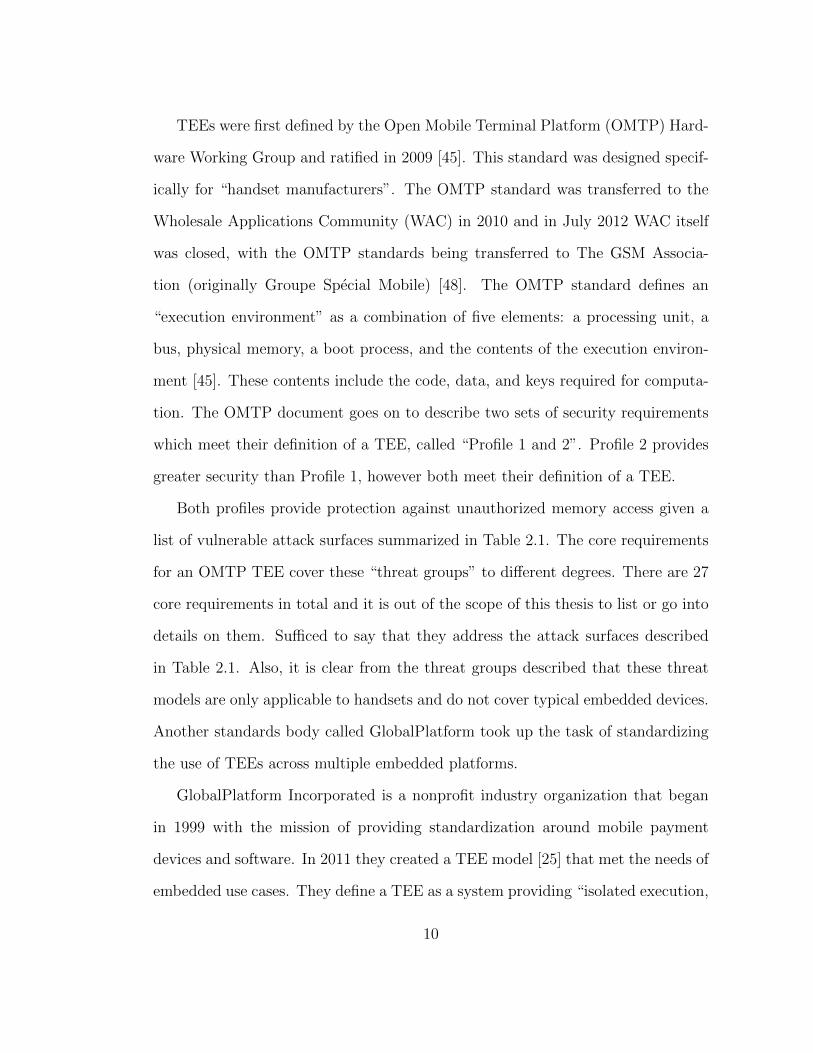
Both profiles provide protection against unauthorized memory access given a
list of vulnerable attack surfaces summarized in Table 2.1. The core requirements
for an OMTP TEE cover these “threat groups” to different degrees. There are 27
core requirements in total and it is out of the scope of this thesis to list or go into
details on them. Sufficed to say that they address the attack surfaces described
in Table 2.1. Also, it is clear from the threat groups described that these threat
models are only applicable to handsets and do not cover typical embedded devices.
Another standards body called GlobalPlatform took up the task of standardizing
the use of TEEs across multiple embedded platforms.
GlobalPlatform Incorporated is a nonprofit industry organization that began
in 1999 with the mission of providing standardization around mobile payment
devices and software. In 2011 they created a TEE model [25] that met the needs of
embedded use cases. They define a TEE as a system providing “isolated execution,
10
Group Attack Surface
Group 1 Hardware modules used for accessing memories, only including at-tacks mounted via modules built into the “mobile equipment” de-sign (e.g. DMA module)
Group 2 Colour LCD controllers or “graphics chip of the mobile device”designed to be pointed at memory blocks and could dump thatinformation to the screen
Group 3 Removal of battery or external memory card
Group 4 Replacement of flash when power is off
Group 5 Extract secrets by bus monitoring (e.g. hardware probes)
Group 6 Attached devices (mod chips) used to attack data between flashand the System on Chip (SoC) or in external RAM.
Group 7 Replacement of flash when power is on
Table 2.1: Attack surfaces as grouped by the OMTP. This table is createdfrom data available in section 2.1 of the OMTP document. [45]
integrity of Trusted Applications (TAs), and integrity and confidentiality of TA
assets” [25]. A GlobalPlatform TEE is more rigorous than the OMTP standard
in that it requires a security certification provided by GlobalPlatform and must
comply with the following GlobalPlatform standards: TEE Protection Profile,
TEE Client API Specification, and TEE Internal Core API Specification [23, 24,
27].
Unlike in the OMTP standard, GlobalPlatform first introduces the concept of
attestation in its definition of a Root of Trust (RoT). We will discuss attestation
in depth for each of our technologies we cover, as well as in chapter 6 where we
consider this property of a TEE and if it can be considered optional [58]. Standards
11
and specifications from groups like OMTP and GlobalPlatforms paved the way for
the creation of mobile devices capable of secure remote computation. Indeed,
the smartphone revolution would only have been possible with the ability to run
trusted applications allowing users to interact with financial, healthcare, and other
valuable data.
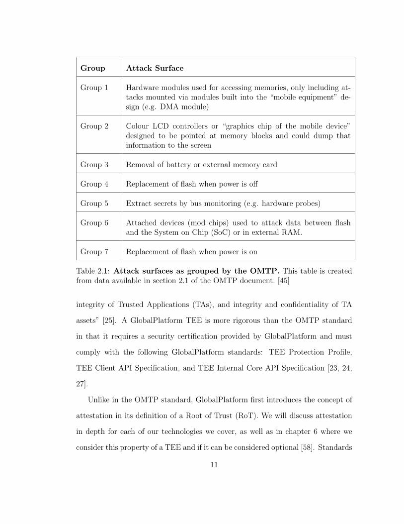
PCB
Power Control IC
System On Chip
I/O Interfaces
Video Keyboard Other
Non-volitile
Memory
(Flash)
VolitileMemory(RAM)
EmbeddedSecure
Element
Removable
Secure
Element
Off-SoCSecurity
Processor
RTC
OtherSecureAssets
Potential TEE hosting components
Other system components
Optional component
Key
Figure 2.1: The board level chipset architecture of a typical mobile device.The concept of an embedded or removable secure element allows for devices like aTPM which may hold secure data but will not host the TEE. A TEE may resideon the SoC itself as with Arm TrustZone. However, it is possible to physicallyseparate the TEE from the SoC and still be compliant with the GlobalPlatformmodel. This figure was recreated and simplified from Figure 2-1 on page 15 of theGlobalPlatform Technology TEE System Architecture Version 1.2. [25].
In Figure 2.1 we see a very common mobile device system diagram with the12
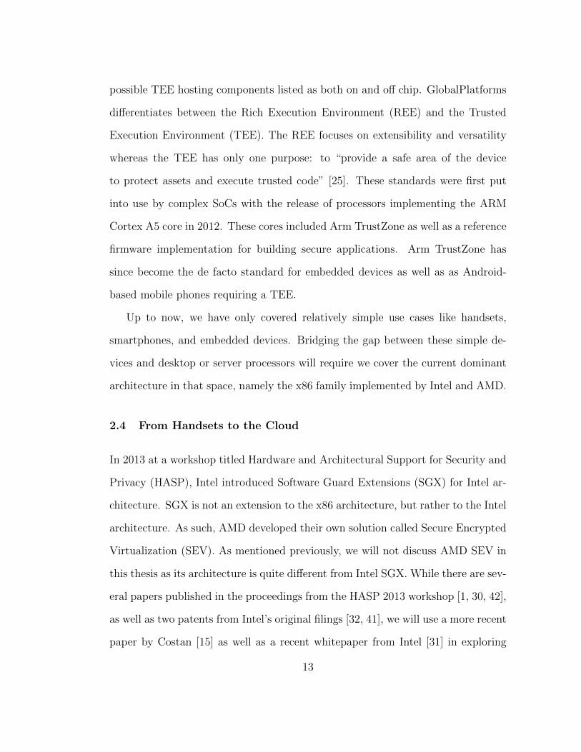
possible TEE hosting components listed as both on and off chip. GlobalPlatforms
differentiates between the Rich Execution Environment (REE) and the Trusted
Execution Environment (TEE). The REE focuses on extensibility and versatility
whereas the TEE has only one purpose: to “provide a safe area of the device
to protect assets and execute trusted code” [25]. These standards were first put
into use by complex SoCs with the release of processors implementing the ARM
Cortex A5 core in 2012. These cores included Arm TrustZone as well as a reference
firmware implementation for building secure applications. Arm TrustZone has
since become the de facto standard for embedded devices as well as as Android-
based mobile phones requiring a TEE.
Up to now, we have only covered relatively simple use cases like handsets,
smartphones, and embedded devices. Bridging the gap between these simple de-
vices and desktop or server processors will require we cover the current dominant
architecture in that space, namely the x86 family implemented by Intel and AMD.
2.4 From Handsets to the Cloud
In 2013 at a workshop titled Hardware and Architectural Support for Security and
Privacy (HASP), Intel introduced Software Guard Extensions (SGX) for Intel ar-
chitecture. SGX is not an extension to the x86 architecture, but rather to the Intel
architecture. As such, AMD developed their own solution called Secure Encrypted
Virtualization (SEV). As mentioned previously, we will not discuss AMD SEV in
this thesis as its architecture is quite different from Intel SGX. While there are sev-
eral papers published in the proceedings from the HASP 2013 workshop [1, 30, 42],
as well as two patents from Intel’s original filings [32, 41], we will use a more recent
paper by Costan [15] as well as a recent whitepaper from Intel [31] in exploring
13
SGX.
Intel’s introduction of SGX opened up the desktop and laptop markets to a new
type of software application capable of hardware-backed secure “enclaves”. It also
gave application developers on Intel platforms the chance to utilize both local and
remote attestation, providing assurance from the vendor regarding code integrity
and confidentiality. It wasn’t until 2021 that Intel would make this technology
available in multi-socket Xeon CPUs, opening the door for cloud providers to take
advantage of TEEs on Intel platforms [13].
2.5 RISC-V: An Open Source TEE
RISC-V is a popular modern architecture developed at the Parallel Computing Lab
(Par Lab), which is part of the University of California at Berkeley. Perhaps the
most notable thing about this architecture is that it has been developed using the
same methodology as open source software. The specifications are published using
a Creative Commons license, and all code examples or artifacts of the specification
use permissive licenses like the BSD licenses or the Apache license [62]. The work
done on the RISC-V specifications is overseen by a non-profit organization called
RISC-V International, an organization registered in Switzerland.
The Trusted Execution Environment Task Group of RISC-V International has
developed a specification called Physical Memory Protection (PMP) as part of
the RISC-V Privileged Specification [63]. RISC-V PMP extends the concept of
Physical Memory Attributes (PMA) to include multiple configurable sections of
memory whose access rights can be altered by firmware running at the highest priv-
ilege level. RISC-V PMP is certainly a very basic type of TEE, however plans to
14
extend its capabilities have already been drafted in a new specification called Ex-
tended Physical Memory Protection (ePMP). Likewise, drafts of S-Mode Physical
Memory Protection (sPMP) and I/O Physical Memory Protection (IOPMP) are
set for ratification in 2021. We will discuss all of these types of memory protection
in detail in chapter 5.
This chapter has given a brief background of Trusted Execution Environments
(TEEs) and we have been selective in mentioning only a few of the many examples
of hardware security that influenced the development of TEEs. We have shown that
any given TEE builds off the technologies of the past, even when incorporating new
instructions or hardware unique to TEEs. As we will see, without technologies and
standards like the TPM ISO standard of 2009, TEEs would not have the means
to perform many of the advanced features like attestation which are critical to
some applications. We continue now with an overview of our three technologies
for comparison: Intel Software Guard Extensions (SGX), Arm TrustZone, and
RISC-V Physical Memory Protection (PMP).
15

A Timeline of TEE Related Events
1990 • Intel releases SMM
2005 • First processor using VT-x released
2006 • Firmware vulnerabilities in SMM published
2008 • Intel ME releasedFirst VM Escape CVEs published
2009 • OMTP TEEs standard publishedTPM ISO standard
2011 • GlobalPlatform TEE specification published
2012 • ARM Cortex-A5 with TrustZone
2013 • TrustZone vulnerability publishedIntel introduces Software Guard Extensions (SGX)
2015 • Intel Skylake chips with SGX publicly available
2016 • Intel ME rootkit CVE publishedSGX attack published [64]
2017 • RISC-V PMP specification ratifiedSGX critical CVE published
2019 • Microsemi releases SoC with RISC-V PMP
2020 • RISC-V ePMP, sPMP, IOPMP specifications drafted
Figure 2.2: An overview of modern hardware security features, specifica-tions, and vulnerabilities In this timeline, events pertaining to TEEs are in blueand vulnerabilities in hardware security technologies are in red. Dates of vulner-abilities are not exact, see https://cve.mitre.org/ for exact dates and severity.Dates of technology releases are estimates and taken by the first broadly availableproduct release with the given feature available.
16
Chapter 3
Intel Software Guard Extensions
3.1 The Intel SGX Solution
Intel Software Guard Extensions (SGX) is built on designs of software attestation
already proven in technologies like the Trusted Platform Module (TPM) and Intel
Trusted Execution Technology (TXT). In SGX, these concepts of software attesta-
tion are used to create containerized sections of memory on the remote computer
called “secure enclaves” where data and code can be loaded or executed securely.
These enclaves are verified by both a cryptographic attestation key of the con-
tainer’s contents as well as a hardware Root of Trust (RoT) manufacturer’s key.
Unlike the TPM and TXT technologies, SGX securely operates only on a small
amount of data and code called the Trusted Compute Base (TCB), leaving the
majority of memory outside this TCB.
3.2 Initial SGX Enclave Setup
Configuration settings for SGX exists as part of the platform firmware, and most
firmware vendors provide simple tools for enabling SGX. If SGX is enabled, the
firmware is responsible for setting aside a memory region called the Processor
Reserved Memory (PRM), and most firmware tools allow specifying the size of the
space allocated. The firmware allocates the PRM by setting a pair of model-specific
registers (MSRs), collectively known as the PRMRR. The CPU will then protect
the PRM from all non-enclave memory accesses including kernel, hypervisor and
System Management Mode (SMM) accesses, as well as Direct Memory Access
17
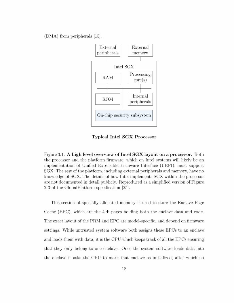
(DMA) from peripherals [15].
RAM
ROMInternal
peripherals
Processingcore(s)
Intel SGX
Externalmemory
Externalperipherals
On-chip security subsystem
Typical Intel SGX Processor
Figure 3.1: A high level overview of Intel SGX layout on a processor. Boththe processor and the platform firmware, which on Intel systems will likely be animplementation of Unified Extensible Firmware Interface (UEFI), must supportSGX. The rest of the platform, including external peripherals and memory, have noknowledge of SGX. The details of how Intel implements SGX within the processorare not documented in detail publicly. Reproduced as a simplified version of Figure2-3 of the GlobalPlatform specification [25].
This section of specially allocated memory is used to store the Enclave Page
Cache (EPC), which are the 4kb pages holding both the enclave data and code.
The exact layout of the PRM and EPC are model-specific, and depend on firmware
settings. While untrusted system software both assigns these EPCs to an enclave
and loads them with data, it is the CPU which keeps track of all the EPCs ensuring
that they only belong to one enclave. Once the system software loads data into
the enclave it asks the CPU to mark that enclave as initialized, after which no
18
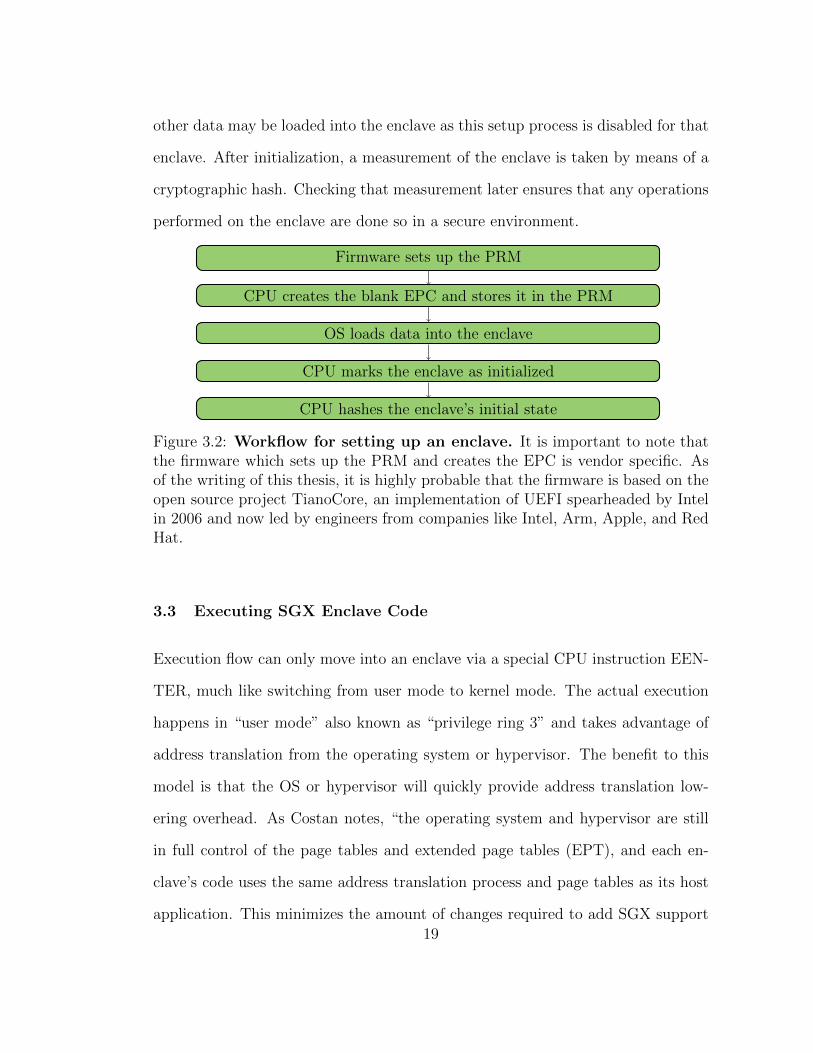
other data may be loaded into the enclave as this setup process is disabled for that
enclave. After initialization, a measurement of the enclave is taken by means of a
cryptographic hash. Checking that measurement later ensures that any operations
performed on the enclave are done so in a secure environment.
Firmware sets up the PRM
CPU creates the blank EPC and stores it in the PRM
OS loads data into the enclave
CPU marks the enclave as initialized
CPU hashes the enclave’s initial state
Figure 3.2: Workflow for setting up an enclave. It is important to note thatthe firmware which sets up the PRM and creates the EPC is vendor specific. Asof the writing of this thesis, it is highly probable that the firmware is based on theopen source project TianoCore, an implementation of UEFI spearheaded by Intelin 2006 and now led by engineers from companies like Intel, Arm, Apple, and RedHat.
3.3 Executing SGX Enclave Code
Execution flow can only move into an enclave via a special CPU instruction EEN-
TER, much like switching from user mode to kernel mode. The actual execution
happens in “user mode” also known as “privilege ring 3” and takes advantage of
address translation from the operating system or hypervisor. The benefit to this
model is that the OS or hypervisor will quickly provide address translation low-
ering overhead. As Costan notes, “the operating system and hypervisor are still
in full control of the page tables and extended page tables (EPT), and each en-
clave’s code uses the same address translation process and page tables as its host
application. This minimizes the amount of changes required to add SGX support19

to existing system software.” [15]. The downside is that code executing inside the
enclave does not have access to system calls (syscall) or any other high privilege
operations. An inability to make system calls limits the types of operations that
can be preformed inside an enclave. The code executing inside the enclave does
have access to its entire address space which includes the “host application” that
caused the creation of the enclave.
The CPU executing the enclave code will perform an Asynchronous Enclave
Exit (AEX) whenever execution moves outside the enclave such as servicing an
interrupt or during a page fault. The CPU state is saved inside the enclave memory
metadata before exiting, ensuring that the CPU can securely restore the state of
enclave execution. There are special machine mode CPU instructions that are used
both in allocating EPC pages to the enclave as well as evicting those pages into
untrusted DRAM. Page management instructions allow code outside the enclave
to operate on code within the enclave. SGX uses cryptographic protections to
assure the confidentiality, integrity, and “freshness” [15] of the evicted EPC pages
while they are stored in untrusted memory.
As mentioned the application that makes calls into an enclave or “host appli-
cation” lives in the same address space as the enclave code and data. Restricting
host and enclave to the same address space has benefits in terms of application
size variability, but may open the host application up to attack should the enclave
code become compromised [55]. SGX allows enclaves to execute multiple threads
through a Thread Control Structure (TCS) which allows multiple logical cores to
execute enclave code. Within the EPC metadata, reserved secure memory called
the State Save Area (SSA) allows the threads to save their state when a context
switch happens, like servicing an interrupt. In this way, Intel SGX is able to allow
20

a specific amount of code and data to remain protected while still allowing access
to that data by code outside the trust boundary.
3.4 Life Cycle of an SGX Enclave
non-existent
notinitialized
initializedinitialized(in use)
ECREATE
EINIT
EADDEEXTEND
page manage-ment instructions
EENTERERESUME
EEXITAEX
EREMOVE
page manage-ment instructions
EGETKEYEREPORT
Figure 3.3: Intel SGX enclave life cycle. The enclave’s memory is protected instates shaded blue. Note that in the enclave is not secure while in the uninitializedstate as pages are being added or extended. Until a measurement is loaded intothe MRENCLAVE register, code and data integrity can not be assured. The CPUwill call AEX in order to service interrupts, and the state of the enclave will besaved in the SSA. Reprinted as a simplified version from Costan’s Figure 63 [15].
In order to understand the life cycle of an enclave, we must consider the spe-
cific x86 instructions used to create and manage these enclaves. Many of these
instructions which create enclaves, extend pages, and remove enclaves operate in
“privilege ring 0”, one of the most privileged modes. Whereas attestation, enter-
ing, and exiting the enclave can be done from “privilege ring 3” the least privileged
21
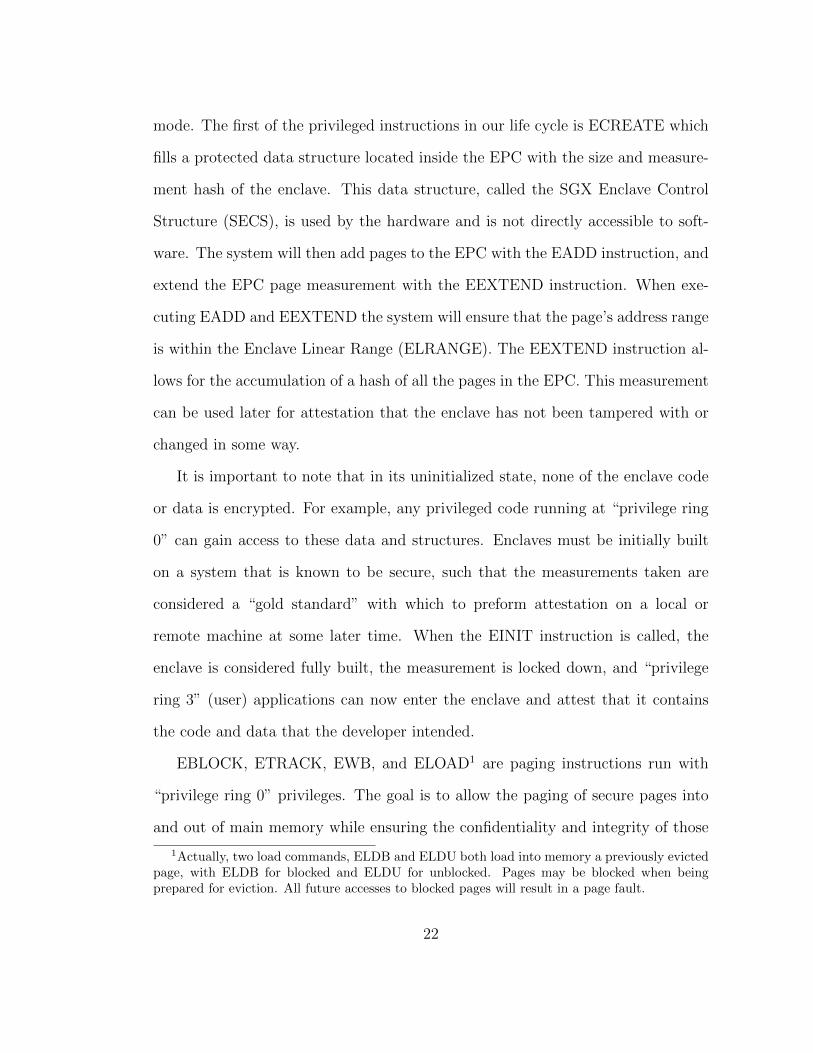
mode. The first of the privileged instructions in our life cycle is ECREATE which
fills a protected data structure located inside the EPC with the size and measure-
ment hash of the enclave. This data structure, called the SGX Enclave Control
Structure (SECS), is used by the hardware and is not directly accessible to soft-
ware. The system will then add pages to the EPC with the EADD instruction, and
extend the EPC page measurement with the EEXTEND instruction. When exe-
cuting EADD and EEXTEND the system will ensure that the page’s address range
is within the Enclave Linear Range (ELRANGE). The EEXTEND instruction al-
lows for the accumulation of a hash of all the pages in the EPC. This measurement
can be used later for attestation that the enclave has not been tampered with or
changed in some way.
It is important to note that in its uninitialized state, none of the enclave code
or data is encrypted. For example, any privileged code running at “privilege ring
0” can gain access to these data and structures. Enclaves must be initially built
on a system that is known to be secure, such that the measurements taken are
considered a “gold standard” with which to preform attestation on a local or
remote machine at some later time. When the EINIT instruction is called, the
enclave is considered fully built, the measurement is locked down, and “privilege
ring 3” (user) applications can now enter the enclave and attest that it contains
the code and data that the developer intended.
EBLOCK, ETRACK, EWB, and ELOAD1 are paging instructions run with
“privilege ring 0” privileges. The goal is to allow the paging of secure pages into
and out of main memory while ensuring the confidentiality and integrity of those
1Actually, two load commands, ELDB and ELDU both load into memory a previously evictedpage, with ELDB for blocked and ELDU for unblocked. Pages may be blocked when beingprepared for eviction. All future accesses to blocked pages will result in a page fault.
22
pages. Information stored inside the EPC called the Paging Crypto MetaData
(PCMD) keeps track of the identity of the enclave the page belongs to and a
pointer to an access rights structure. There is also a Version Array (VA) which is
used to store the version numbers of pages evicted from the EPC. These versioned
and access controlled pages are therefore hardware protected, and any change to
the versioning, access rights, or origins of the page will result in a page fault. It is
possible to have 2 instances of the same enclave, however pages cannot be swapped
between them, and the hashes of these pages will not be the same.
Once an application has requested that “privilege ring 0” components build the
enclave and EENTER is called, the enclave may begin execution. The hardware is
responsible for saving (AEX) and restoring (ERESUME) the architectural state of
execution should any external events like interrupts or exceptions cause execution
to leave the enclave. The EGETKEY and EREPORT instructions operate in user
mode (“privilege ring 3”) and seal data based on the key the developer provides.
Using these two instructions SGX applications operating in “privilege ring 3” are
able to preform local attestation of the enclave, perhaps the most vital function of
any Trusted Execution Environment (TEE). Finally, once the enclave is no longer
needed, the system will call EEXIT, and a synchronous enclave exit will occur. As
Costan notes, “EEXIT does not modify most registers, so enclave authors must
make sure to clear any secrets stored in the processor’s registers before returning
control to the host process.” [15].
3.5 Attestation with Intel SGX
Software attestation of enclaves is required to ensure the integrity of the enclave.
This attestation can happen locally between two enclaves on the same platform or
23
remotely between two different platforms. As previously noted, the measurement
of the enclave includes a SHA-256 hash of the enclave’s attributes as well as the
content, position, and access rights of its pages. This measurement is stored in a
register called MRENCLAVE which represents the enclave’s TCB. The EREPORT
instruction is used to generate a signed report of this TCB and the EGETKEY
instruction then retrieves the key used to validate said report. Local attestation of
enclaves can be done using symmetric encryption as the hardware can ensure the
integrity of the single key being used to verify the MRENCLAVE value. Remote
attestation must be done using asymmetric encryption (both a public and private
key) and requires the remote SGX enabled platform to query an Intel attestation
server.
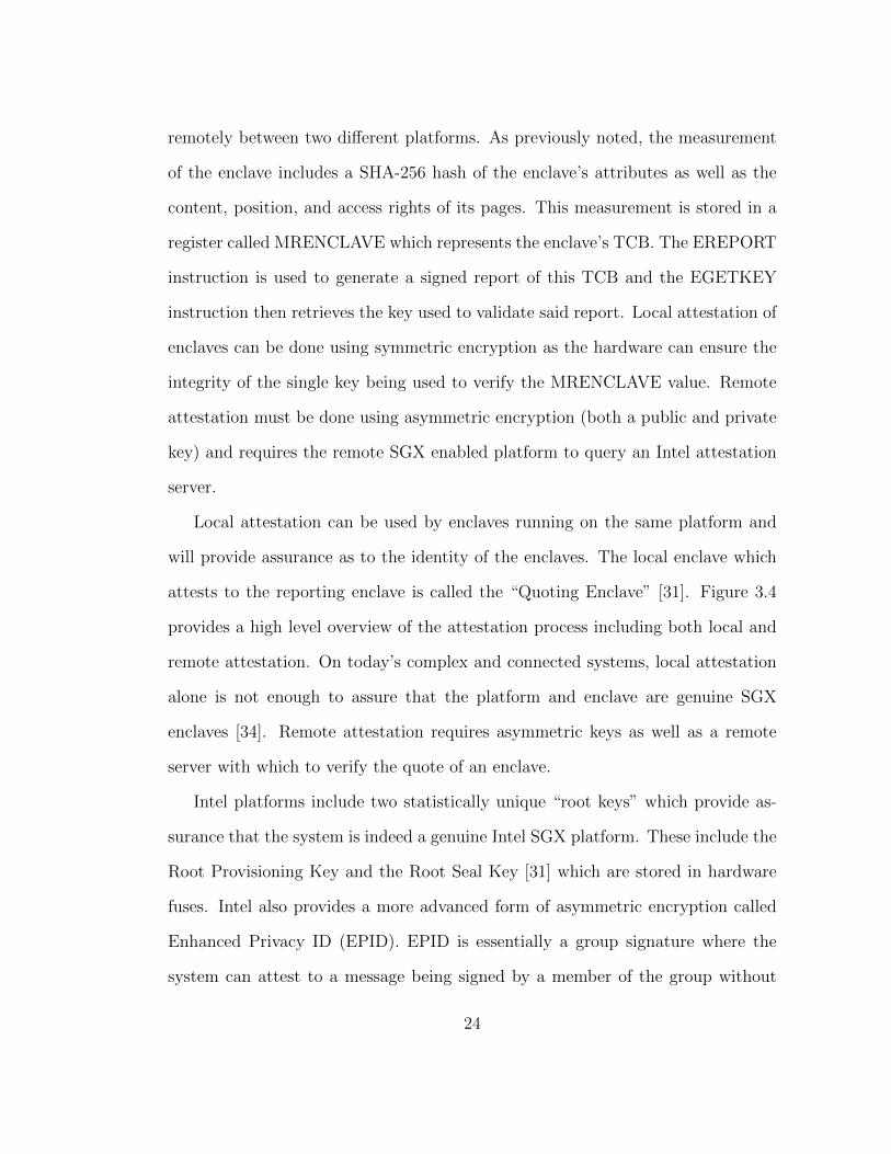
Local attestation can be used by enclaves running on the same platform and
will provide assurance as to the identity of the enclaves. The local enclave which
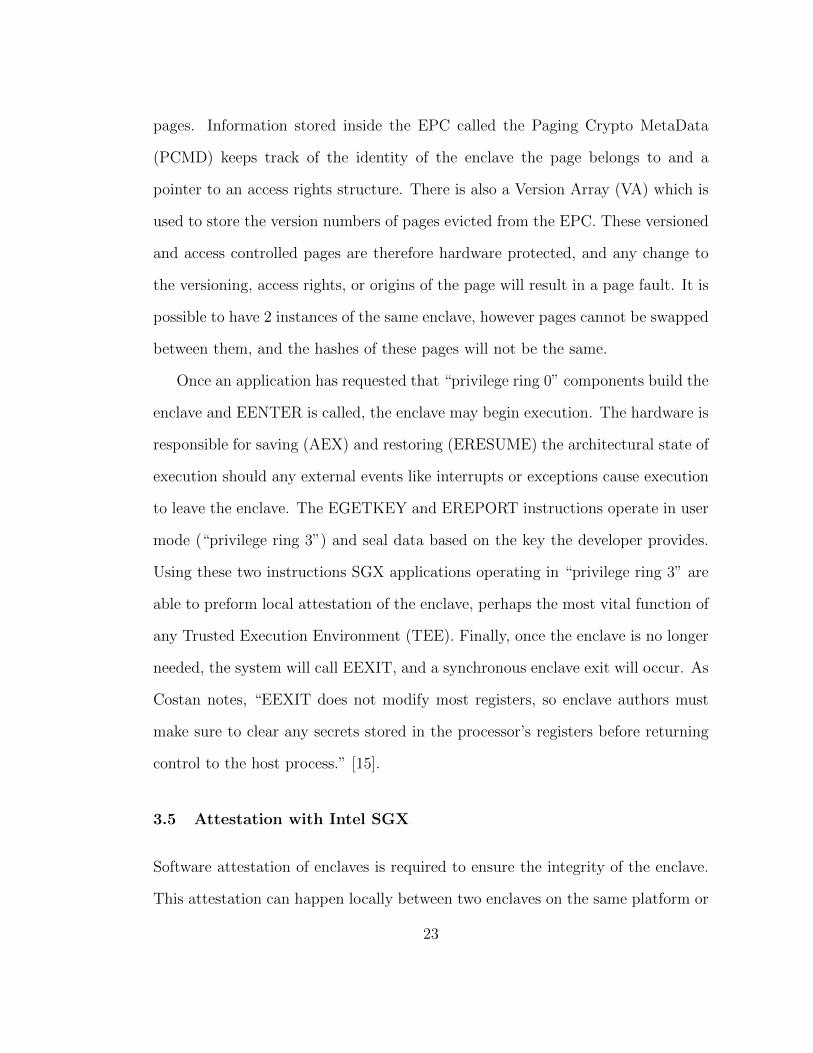
attests to the reporting enclave is called the “Quoting Enclave” [31]. Figure 3.4
provides a high level overview of the attestation process including both local and
remote attestation. On today’s complex and connected systems, local attestation
alone is not enough to assure that the platform and enclave are genuine SGX
enclaves [34]. Remote attestation requires asymmetric keys as well as a remote
server with which to verify the quote of an enclave.
Intel platforms include two statistically unique “root keys” which provide as-
surance that the system is indeed a genuine Intel SGX platform. These include the
Root Provisioning Key and the Root Seal Key [31] which are stored in hardware
fuses. Intel also provides a more advanced form of asymmetric encryption called
Enhanced Privacy ID (EPID). EPID is essentially a group signature where the
system can attest to a message being signed by a member of the group without
24
Challenger
AttestationVerification
ApplicationApplication
EnclaveUser Data ö
QuotingEnclave
AttestationKey ö
RemotePlatform
User Platform
1
6
2
3
4 57
Figure 3.4: Local and remote attestation of an Intel SGX enclave. A remotechallenger may request that an application provide attestation. The applicationmust then request a report from the enclave and locally verify that against aquoting enclave. The quoting enclave will use the remote along with asymmetrickeys to produce a remote attestation “quote” to be returned to the challenger.The challenger may then use some verification service to check the validity of thequote. This figure was reproduced from Figure 1 [31].
divulging the identify of the signer. The signature algorithm is nothing new [11]
and has been included in the ISO/IEC 20008 and 20009 standards. EPID includes
several revocation schemes which allow keys to be revoked based on checks per-
formed by the verifier and/or issuer. The Intel Attestation Service (IAS) will take
submission of quotes provided, verify the validity of the signatures, and verify that
they have not been revoked.
In this chapter, we have briefly described Intel Software Guard Extensions
(SGX) from the initial setup of the enclave through to the remote attestation of
that enclave’s contents. This system is by far the most complex of the three we will
examine in this thesis. We have only covered the properties that are necessary to
25

understand if we are to appropriately apply our method of comparison. Depend-
ing on the use case, a much more in depth knowledge of SGX may be required.
However, this thesis will show that even with this rudimentary understanding, one
can still apply rigorous method to analysing features of a TEE. Next, we will cover
Arm’s framework for building TEEs called TrustZone, as well as the reference im-
plementations of their firmware: Trusted Firmware-A (TF-A) and Open-source
Portable TEE (OP-TEE).
26
Chapter 4
Arm TrustZone
4.1 The Arm TrustZone Solution
Arm released TrustZone in 2004 for their “general purpose compute” cores, and
only as recently as 2016 did they extend this technology to their cores designed
for microcontrollers [51]. When evaluating how Arm’s TrustZone works, we must
remember several important distinctions. Firstly, the Arm specifications include
several different architectures with several different states. Each Arm architecture
and state combination may operate slightly differently in regard to how TrustZone
is implemented. This thesis will only consider the ARMv8-A architecture1 running
in the AArch642 state. Secondly, because Arm Limited licenses their cores to
hardware manufacturers, System on Chips (SoCs) and platforms may choose to
implement security in many ways, and with much more flexibility than in Intel
platforms. For simplicity’s sake, this thesis will only cover firmware solutions
for TrustZone implementations provided by Linaro’s open source projects Trusted
Firmware-A (TF-A) and Open-source Portable TEE (OP-TEE).
Arm SoC processors create a more absolute separation between the concepts of
“secure” and “normal or insecure” operation than Intel Software Guard Extensions
(SGX). At its highest level this is accomplished using the Secure Configuration
1Arm Limited produces three ISA profiles [3]: A-Profile for general purpose compute, R-Profilefor real-time, and M-Profile for microcontrollers. These profiles can be seen in the architectureversion naming scheme, such that ARMv8-A is “version 8” of the ARM instruction set, with afocus on general purpose compute. The cores that Arm Limited licenses to customers are labeled“Cortex”, with ARM Cortex-A55 referencing a specific microarchitecture implementation of theARMv8-A ISA.
2AArch64 is the 64-bit state of any ARMv8-A core which is capable of also running in the32-bit state called AArch32 [3].
27
Register (SCR) “Non-Secure bit” (NS) with 1 meaning non-secure and 0 meaning
secure. This is perhaps the most fundamental element that separates Arm’s two
security worlds. Digging a bit deeper, this separation of worlds is accomplished
using four separate primitives: one on the bus, one on the SoC core, one as part
of the memory infrastructure, and finally one as part of the debug infrastructure.
RAM
ROMInternal
peripherals
Processingcore(s)
SoC
Externalmemory
Externalperipherals
One Possible TrustZone Platform
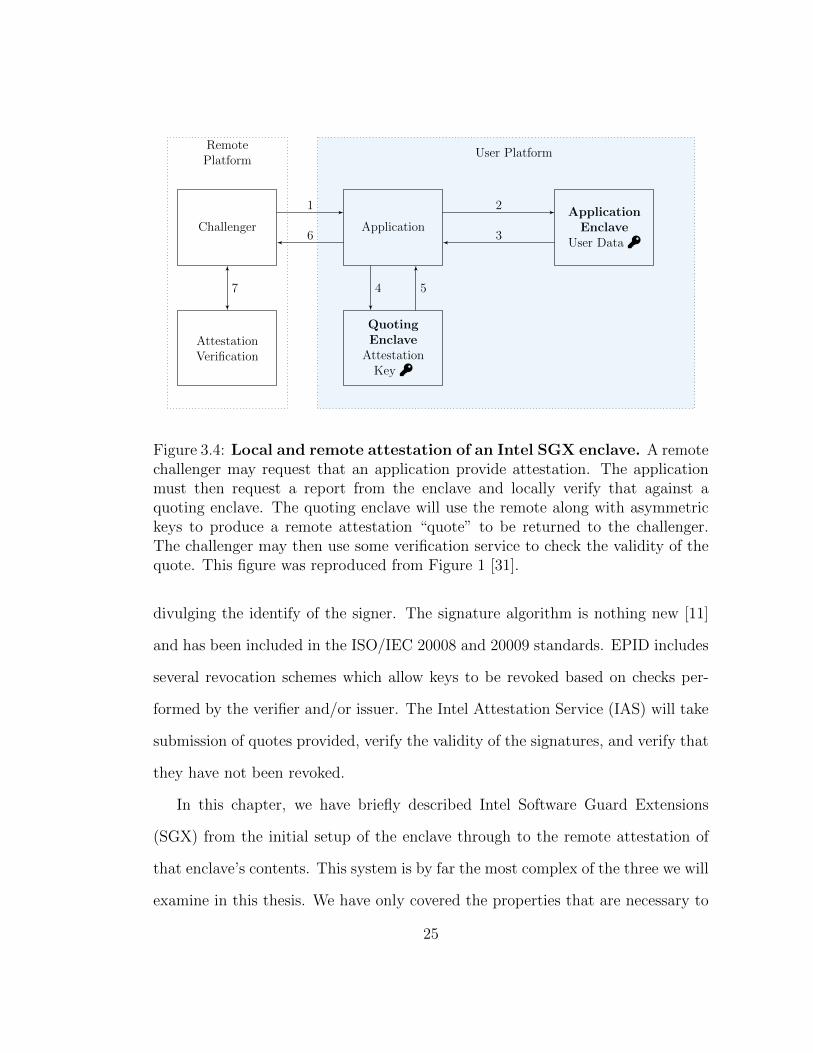
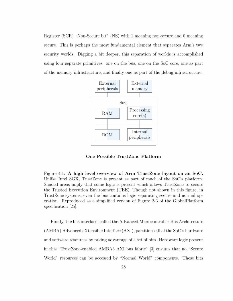
Figure 4.1: A high level overview of Arm TrustZone layout on an SoC.Unlike Intel SGX, TrustZone is present as part of much of the SoC’s platform.Shaded areas imply that some logic is present which allows TrustZone to securethe Trusted Execution Environment (TEE). Though not shown in this figure, inTrustZone systems, even the bus contains logic separating secure and normal op-eration. Reproduced as a simplified version of Figure 2-3 of the GlobalPlatformspecification [25].
Firstly, the bus interface, called the Advanced Microcontroller Bus Architecture
(AMBA) Advanced eXtensible Interface (AXI), partitions all of the SoC’s hardware
and software resources by taking advantage of a set of bits. Hardware logic present
in this “TrustZone-enabled AMBA3 AXI bus fabric” [3] ensures that no “Secure
World” resources can be accessed by “Normal World” components. These bits
28
include AWPROT for write transactions and ARPROT for read transactions where
like the NS bit low is Secure and high is Non-secure.
Secondly, SoCs which implement the ARMv8-A instruction set must also im-
plement extensions which enable a single physical processor core to safely and
efficiently execute code from both the Normal World and the Secure World in a
time-sliced fashion [44]. The value of the Non-Secure bit is read from the SCR
and passed along down the bus to the memory controller and peripherals. A new
instruction, the Secure Monitor Call (SMC), is added which allows the core to
switch between the secure and normal modes. We will discuss the secure monitor
firmware which is responsible for handling these interrupts in the next section.
Thirdly, the memory infrastructure includes security features like TrustZone
Address Space Controller (TZASC) and TrustZone Memory Adapter (TZMA) [44].
The TZASC allows for configuration of the secure and normal world memory re-
gions. It does so by partitioning DRAM into areas which have secure world access
and those regions which have normal world access. This process can only be done
from the secure world. The TZMA serves a similar function for any off-chip mem-
ory such as an off-chip ROM. The way in which this memory partitioning happens
is based on the specific SoC implementing TrustZone. SoC manufacturers can
provide robust or simple partitioning and it is important to understand the imple-
mentation of your specific SoC’s memory controller to properly understand how
TrustZone has been implemented.
Lastly, the security-aware debug infrastructure controls debug access to the
Secure World. This includes “secure privileged invasive (JTAG) debug, secure
privileged non-invasive (trace) debug, secure user invasive debug, and secure user
non-invasive debug” [3]. By using two different signals into the core along with two
29
different bits in a secure register, the core can report either invasive or non-invasive
debug info. In this way, the core is able to debug either the normal world only, or
it can debug both the secure and normal worlds together. These four primitives
provide a framework or scaffolding on which to build a platform capable of secure
computation.
In the next section we discuss the firmware that will implement a TEE using
TrustZone’s features. First, we will point out a potentially confusing difference
between how Intel and Arm create privilege levels. Unlike Intel platforms which
refer to their privilege levels as privilege rings, Arm uses “Exception Levels” EL0
through EL3 [4]. Here EL3 is the highest, most privileged level where as EL0 is the
lowest and least privileged level. Much like with the x86 architecture, exceptions
like data aborts, prefetch aborts, and other interrupts can be taken from the level
at which they occur to the same or any higher privileged level, but not a level
which has less privileges. So, for example, an interrupt occurring in the OS kernel
(EL1) can be handled in the kernel or in the secure monitor (EL3), but not in
the lower privileged application level (EL0). Practically speaking this means that
the user applications running on a system which has not been compromised will
not have access to kernel or lower exceptions. Another common confusion point
between Arm and Intel is that Intel’s “privilege ring 0” is the highest privilege
level while Arm’s “EL0” is the lowest privilege level.
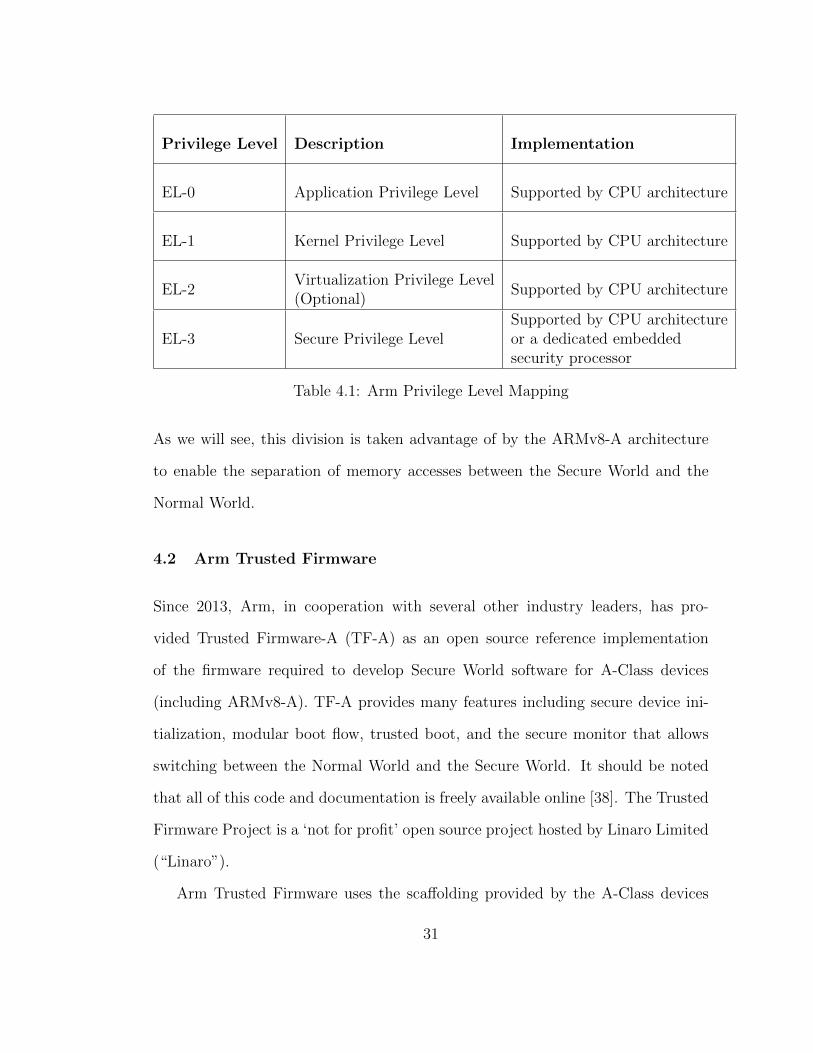
See Table 4.1 for a complete list of privilege levels, their description, and how
they might be implemented in an ARMv8-A system. Each exception level man-
ages its own page tables and control registers with the exception of EL0 which is
managed by EL1 [4]. This is a common practice across architectures where the
kernel level mode controls the page table for the applications running on top of it.
30
Privilege Level Description Implementation
EL-0 Application Privilege Level Supported by CPU architecture
EL-1 Kernel Privilege Level Supported by CPU architecture
EL-2Virtualization Privilege Level(Optional)
Supported by CPU architecture
EL-3 Secure Privilege LevelSupported by CPU architectureor a dedicated embeddedsecurity processor
Table 4.1: Arm Privilege Level Mapping
As we will see, this division is taken advantage of by the ARMv8-A architecture
to enable the separation of memory accesses between the Secure World and the
Normal World.
4.2 Arm Trusted Firmware
Since 2013, Arm, in cooperation with several other industry leaders, has pro-
vided Trusted Firmware-A (TF-A) as an open source reference implementation
of the firmware required to develop Secure World software for A-Class devices
(including ARMv8-A). TF-A provides many features including secure device ini-
tialization, modular boot flow, trusted boot, and the secure monitor that allows
switching between the Normal World and the Secure World. It should be noted
that all of this code and documentation is freely available online [38]. The Trusted
Firmware Project is a ‘not for profit’ open source project hosted by Linaro Limited
(“Linaro”).
Arm Trusted Firmware uses the scaffolding provided by the A-Class devices
31
to implement the key aspects of TrustZone, namely Trusted Boot and the Secure
Monitor. There are currently over 30 platforms supported by Trusted Firmware
and because the code is open source (BSD 3-clause), porting new platforms can be
done by following many of the existing open source examples. Before we explore
Arm Trusted Firmware, we must first understand how an Arm platform can be
initialized in a secure state, specifically using Trusted Board Boot (TBB). TBB
is based on two standards, the Arm Trusted Base System Architecture (TBSA)
[5] and the Arm Trusted Board Boot Requirements (TBBR) [6]. Both of these
specifications are client-based solutions and it is likely that server based solutions
are in development internally at Arm.
Cold Reset
Trusted Boot ROM SoC TEE Configuration
Arm Trusted Firmware (ROM or Trusted SRAM)
Trusted OS Execution
Normal World Bootloader Execution
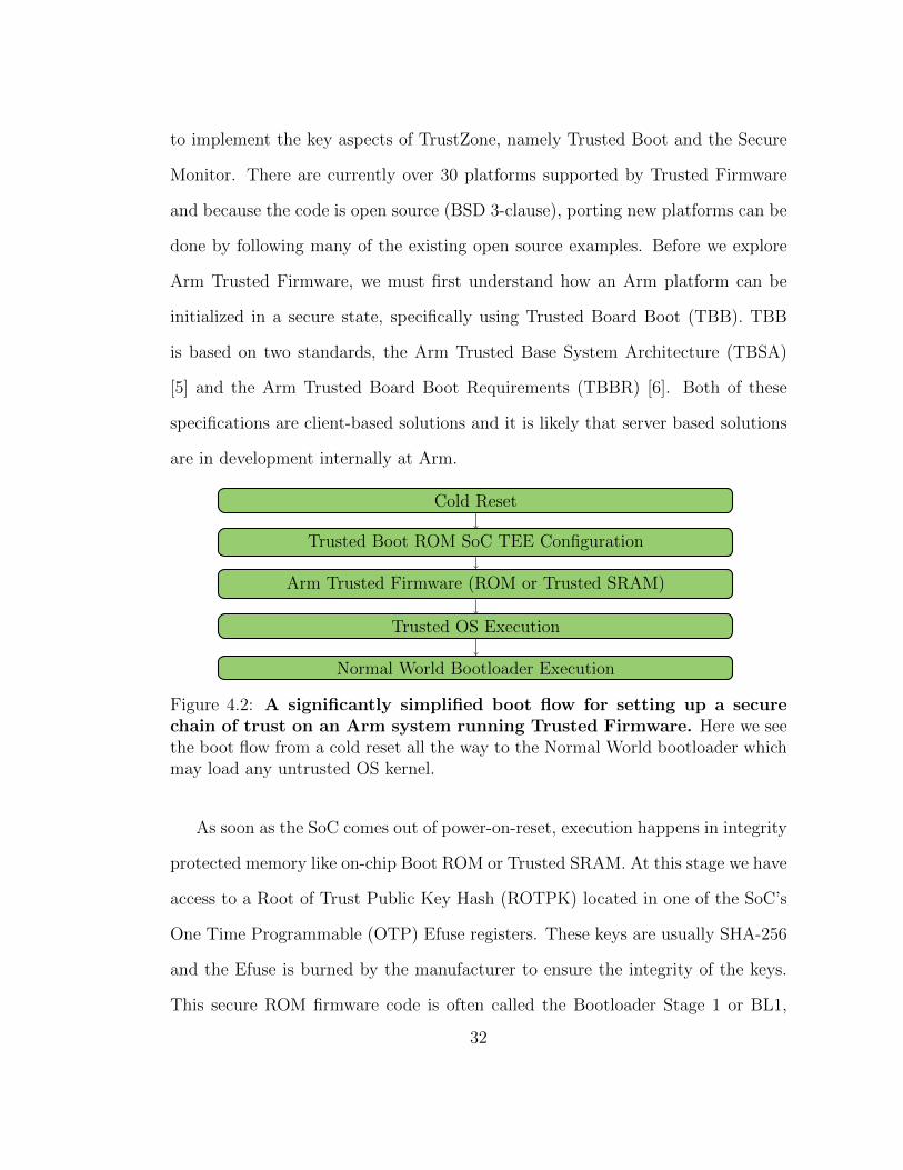
Figure 4.2: A significantly simplified boot flow for setting up a securechain of trust on an Arm system running Trusted Firmware. Here we seethe boot flow from a cold reset all the way to the Normal World bootloader whichmay load any untrusted OS kernel.
As soon as the SoC comes out of power-on-reset, execution happens in integrity
protected memory like on-chip Boot ROM or Trusted SRAM. At this stage we have
access to a Root of Trust Public Key Hash (ROTPK) located in one of the SoC’s
One Time Programmable (OTP) Efuse registers. These keys are usually SHA-256
and the Efuse is burned by the manufacturer to ensure the integrity of the keys.
This secure ROM firmware code is often called the Bootloader Stage 1 or BL1,
32
and it is responsible for checking the validity of the ROTPK. Using this key, BL1
can verify the hash of the next bootloader stage (BL2). The code in BL1 is the
only code that must run in EL3, minimizing the amount of initialization code that
must run at this critical privilege level.
Once in BL2, the code is executing in Secure World EL2 and the firmware can
use the ROTPK to extract the Trusted World ROTPK and the Normal World
ROTPK, which are used in turn to validate the Secure World Trusted OS hash as
well as the Normal World Untrusted OS hash. All of these keys and hashes are
included as extensions to the x.509 standard format, however there is no need for
a valid Certified Authority (CA) certificate, as we are verifying the contents of the
certificates and not the validity of a certificate issuer. BL2 also does some RAM
initialization before it passes off to BL3 where the Secure Monitor is implemented.
This Secure Monitor runs in EL3 and is responsible for loading both the Se-
cure OS as well as the Normal World bootloader. This bootloader might be U-
Boot or some Unified Extensible Firmware Interface (UEFI) implementation like
TianoCore. This Secure Monitor stays resident in memory during the life of the sys-
tem and will manage the interactions between the Normal and Secure Worlds. All
of these stages (BL1 - BL3) of TBB are implemented by Arm’s Trusted Firmware-A
(TF-A) reference implementation.
Once the Trusted Firmware has initialized the system in a secure state, we
have initialized two worlds, the Trusted World and the Normal World. It is per-
haps easiest to think about the interaction between these two worlds in much the
same way we think about making calls from user mode into kernel mode in Linux
systems. In Linux systems, we take advantage of system calls (syscall) to bridge a
trust boundary between the kernel’s concerns like interacting with a network card
33
GenericApplication
App w/Security
SchedulerTrustZone
driver
Security ServiceStandaloneApplication
Cross-worldIPC manager
Scheduler
Secure Monitor
Normal World Secure World
Kernel Kernel
UserPrivileged
EL3 Exception
SMC
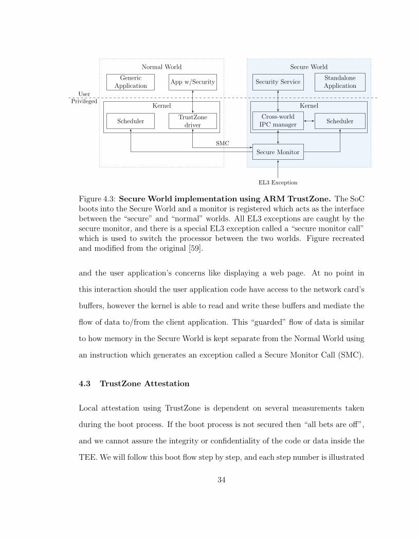
Figure 4.3: Secure World implementation using ARM TrustZone. The SoCboots into the Secure World and a monitor is registered which acts as the interfacebetween the “secure” and “normal” worlds. All EL3 exceptions are caught by thesecure monitor, and there is a special EL3 exception called a “secure monitor call”which is used to switch the processor between the two worlds. Figure recreatedand modified from the original [59].
and the user application’s concerns like displaying a web page. At no point in
this interaction should the user application code have access to the network card’s
buffers, however the kernel is able to read and write these buffers and mediate the
flow of data to/from the client application. This “guarded” flow of data is similar
to how memory in the Secure World is kept separate from the Normal World using
an instruction which generates an exception called a Secure Monitor Call (SMC).
4.3 TrustZone Attestation
Local attestation using TrustZone is dependent on several measurements taken
during the boot process. If the boot process is not secured then “all bets are off”,
and we cannot assure the integrity or confidentiality of the code or data inside the
TEE. We will follow this boot flow step by step, and each step number is illustrated
34
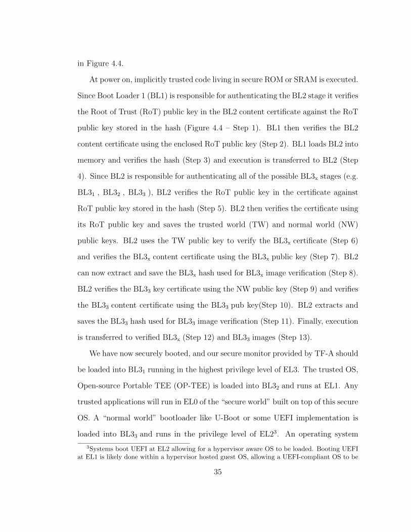
in Figure 4.4.
At power on, implicitly trusted code living in secure ROM or SRAM is executed.
Since Boot Loader 1 (BL1) is responsible for authenticating the BL2 stage it verifies
the Root of Trust (RoT) public key in the BL2 content certificate against the RoT
public key stored in the hash (Figure 4.4 – Step 1). BL1 then verifies the BL2
content certificate using the enclosed RoT public key (Step 2). BL1 loads BL2 into
memory and verifies the hash (Step 3) and execution is transferred to BL2 (Step
4). Since BL2 is responsible for authenticating all of the possible BL3x stages (e.g.
BL31 , BL32 , BL33 ), BL2 verifies the RoT public key in the certificate against
RoT public key stored in the hash (Step 5). BL2 then verifies the certificate using
its RoT public key and saves the trusted world (TW) and normal world (NW)
public keys. BL2 uses the TW public key to verify the BL3x certificate (Step 6)
and verifies the BL3x content certificate using the BL3x public key (Step 7). BL2
can now extract and save the BL3x hash used for BL3x image verification (Step 8).
BL2 verifies the BL33 key certificate using the NW public key (Step 9) and verifies
the BL33 content certificate using the BL33 pub key(Step 10). BL2 extracts and
saves the BL33 hash used for BL33 image verification (Step 11). Finally, execution
is transferred to verified BL3x (Step 12) and BL33 images (Step 13).
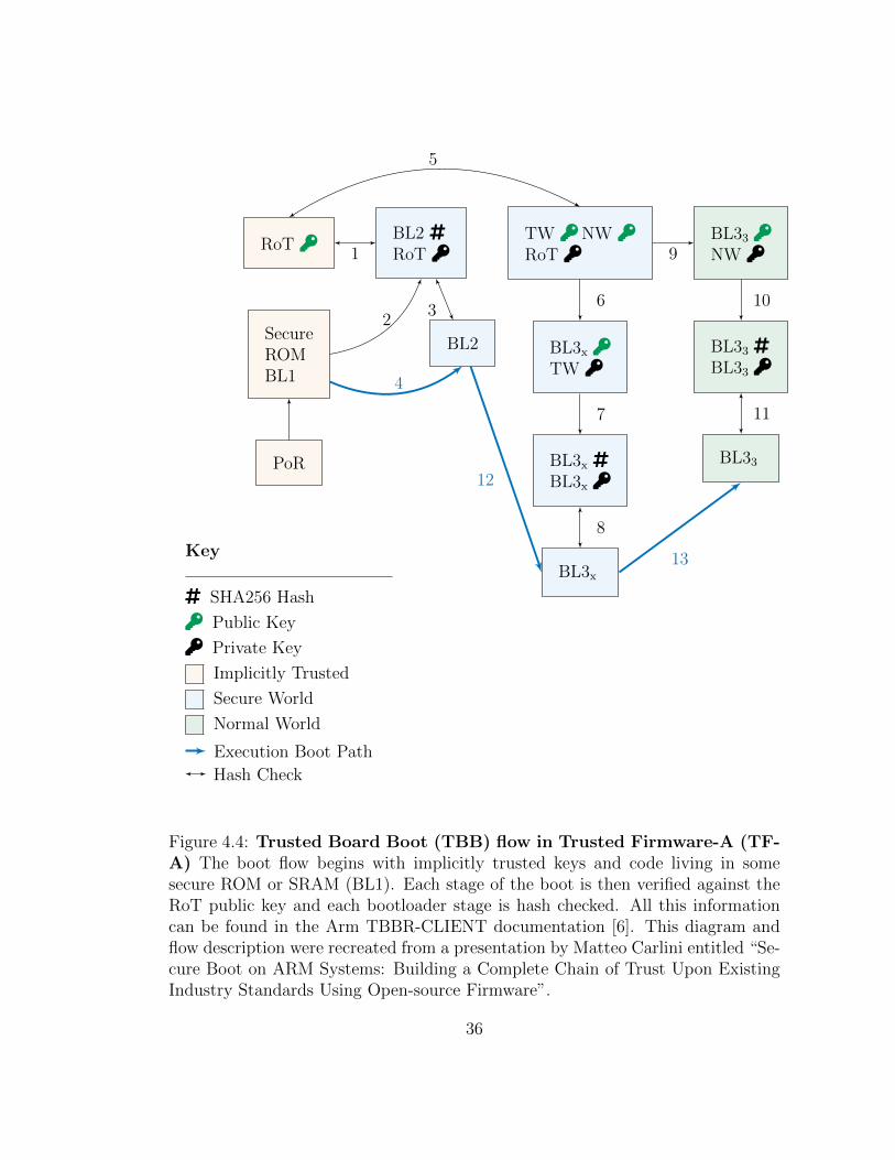
We have now securely booted, and our secure monitor provided by TF-A should
be loaded into BL31 running in the highest privilege level of EL3. The trusted OS,
Open-source Portable TEE (OP-TEE) is loaded into BL32 and runs at EL1. Any
trusted applications will run in EL0 of the “secure world” built on top of this secure
OS. A “normal world” bootloader like U-Boot or some UEFI implementation is
loaded into BL33 and runs in the privilege level of EL23. An operating system
3Systems boot UEFI at EL2 allowing for a hypervisor aware OS to be loaded. Booting UEFIat EL1 is likely done within a hypervisor hosted guest OS, allowing a UEFI-compliant OS to be
35
BL33 ö
NW ö
BL33 ¸
BL33 ö
BL33
TW ö NW ö
RoT ö
BL3x ö
TW ö
BL3x ¸
BL3x ö
BL3x
BL2 ¸
RoT ö
BL2
RoT ö
SecureROMBL1
PoR
Key
¸ SHA256 Hash
ö Public Key
ö Private Key
Implicitly Trusted
Secure World
Normal World
Execution Boot Path
Hash Check
13
12
11
10
9
8
7
6
1
5
2
4
3
Figure 4.4: Trusted Board Boot (TBB) flow in Trusted Firmware-A (TF-A) The boot flow begins with implicitly trusted keys and code living in somesecure ROM or SRAM (BL1). Each stage of the boot is then verified against theRoT public key and each bootloader stage is hash checked. All this informationcan be found in the Arm TBBR-CLIENT documentation [6]. This diagram andflow description were recreated from a presentation by Matteo Carlini entitled “Se-cure Boot on ARM Systems: Building a Complete Chain of Trust Upon ExistingIndustry Standards Using Open-source Firmware”.
36
like Linux or Windows can now load their kernel into memory and will operate at
privilege level EL1. Finally “normal world” applications can be loaded by the OS
and run in privilege mode EL0. These applications can make SMCs with the OP-
TEE kernel driver in the non-secure world to act as a bridge to trusted applications
running in the secure world.
OP-TEE will load Trusted Applications (TAs) into memory when a Rich Ex-
ecution Environment (REE) application makes a request SMC with the corre-
sponding UUID of the TA. For Linux-based systems, the TAs consist of an ELF
binary, signed and possibly encrypted, named from the UUID of the TA. It is the
responsibly of the trusted OS to load the TAs from the REE file system and to
check the integrity of the TAs as part of the chain of trust. OP-TEE maintains a
version database of all the TAs it has loaded and checks the version of each TA
before loading. The version database prevents downgrading of the TA to a earlier,
possibly insecure version.
Since loading a TA from the REE file system creates an inherently larger attack
surface, there are two ways for OP-TEE to load applications from a more secure
location. The first method is known as “early TA” and allows applications to
be linked into the data section of the TEE core blob itself. The “early TA”
method has two benefits: applications can be loaded from a known secure source
and applications can be loaded before the normal world or its file system have
been initialized. The other, more robust option is to load the application from
secured storage, an OP-TEE implementation of the GlobalPlatform specification
for Trusted Storage [25].
OP-TEE secure storage follows the GlobalPlatform TEE Core API document
booted.
37
TrustZonedriver
TA 1 ö TA 2 ö TA 3 ö
TEE Core TEE LibsTEE Functions
TF-A SecureMonitor
Normal World Secure World
Linux Kernel
(OP-TEE) öTrusted OS
UserPrivileged
EL3 Exception
SMC
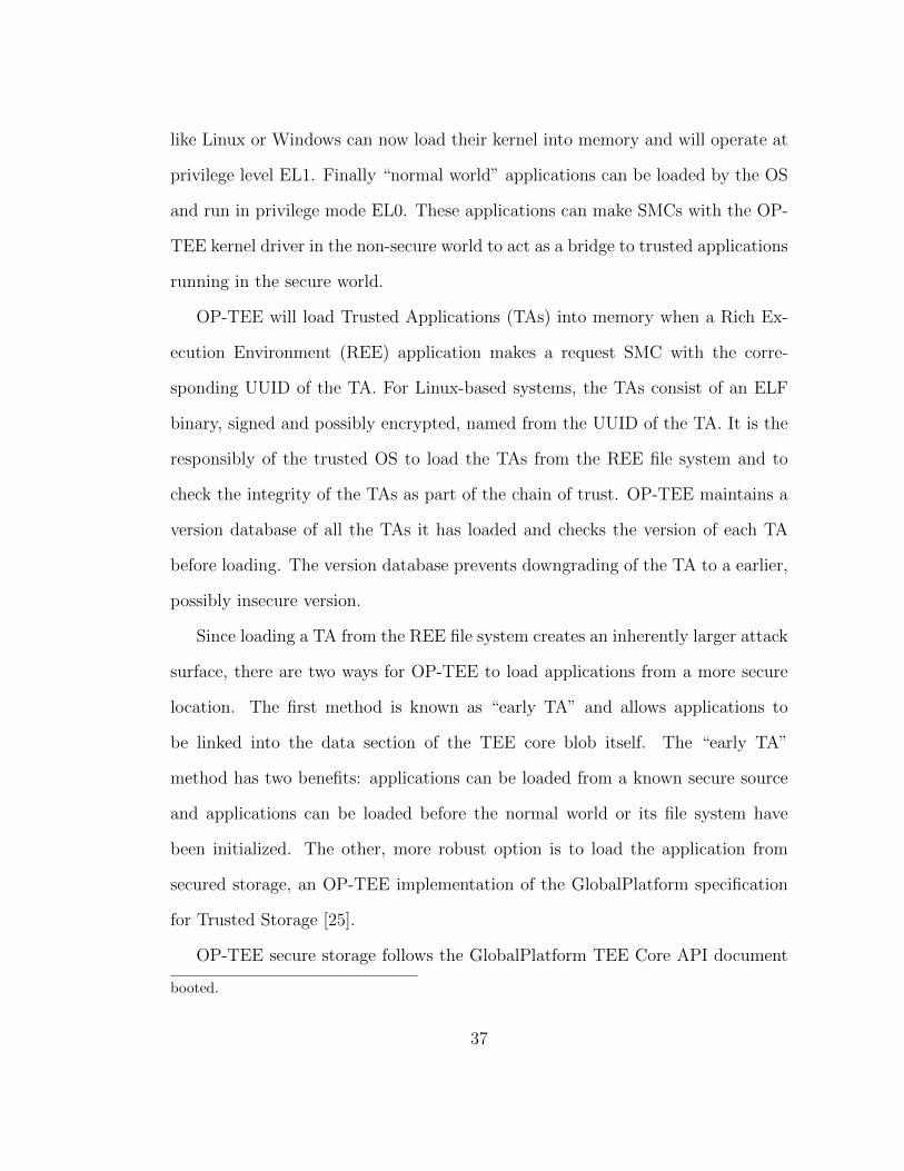
Figure 4.5: The OP-TEE Chain of Trust builds off the secure boot chainof trust. From Figure 4.4, we loaded the secure monitor into BL31 and our secureOS, OP-TEE, into BL32 . With that chain of trust complete, we can now usethe keys present in OP-TEE to load trusted applications into our TEE. The TEEfunctions and libraries actually live in the same area and are separated here onlyfor convenience.
[26] defining “Trusted Storage API for Data and Keys” in section 5. The details
of OP-TEE secure storage are beyond the scope of this thesis. The reader should
understand that regardless of where the applications are loaded from, they are
signed with a key from the trusted OS. OP-TEE Trusted Applications (TAs) are
signed with the pre-generated 2048-bit RSA private key provided by the trusted
OS developer as shown in Figure 4.5. These keys should be stored in a hardware
security module like a Trusted Platform Module (TPM), however the security
model for any given TA is left up to the trusted OS developer. Currently, OP-
TEE only supports one private key per trusted OS. As such, each TA will be signed
with the same key. This step completes the chain of trust and we are able to assure
that each step in loading the application, from PoR to loading the application into
memory, has occurred in a way which preserves the integrity and confidentiality of
38
the data as well as the integrity of the code.
The complexity of remote attestation on mobile platforms, specifically cell
phones, has been well studied and understood for over a decade [43]. There have
been many recent efforts towards a more formally proven type of remote attesta-
tion [12, 20] which can be used in IoT and embedded applications. However, Arm
TrustZone as a framework leaves the implementation of remote attestation as an
exercise for the platform vendor or manufacturer. We will return to this point in
Chapter 6 when we present a comparison of our discussed TEEs.
In this chapter, we have shown how Arm has designed a framework on which
hardware manufacturers and system vendors can hang an implementation of a
TEE. Unlike with Intel SGX, and perhaps core to Arm’s business model, many
of the implementation details are left to the manufacturer. This allows for great
flexibility at the cost of engineering resources and time. Next, we will explore
RISC-V Physical Memory Protection (PMP), and describe a system which is open
source from the ISA through to user space applications. As we will show, open
source specifications allow for even greater flexibility than Arm TrustZone, though
again at a greater cost.
39

Chapter 5
RISC-V Physical Memory Protection
5.1 The RISC-V Open Source ISA
RISC-V is the fifth generation of reduced instruction set computer (RISC) proces-
sors, which have been in development since the 1980s at the University of California
at Berkeley. Hence the name RISC-V has the “five” spelled out as a Roman nu-
meral. One cannot talk about RISC-V’s history without mentioning that of the
MIPS ISA, which began in the same timeframe at Stanford in the 1980s. While
MIPS was very popular in its own right, RISC was the inspiration for many ISAs
including Sun Microsystems’ SPARC line, DEC’s Alpha line, Intel’s i860 and i960
processors, and indeed the ARM processors that most of us now carry in our
pockets.
RISC-V is by no means the first open source ISA. Sun Microsystems intro-
duced the OpenSPARC project in 2005 using the GNU Public License (GPL) [2].
As many students of SoC architecture classes will know, the MIPS architecture
was provided under an “open use” license in a pilot program by Wave Computing
allowing its use in educational settings without licensing fees. ARM has partly
opened its architecture allowing specific partners to proposed changes to the ISA
they license. Many of these changes in industry practices reflect a growing need
for openness in hardware. As Asanovic notes, “While instruction set architectures
(ISAs) may be proprietary for historical or business reasons, there is no good tech-
nical reason for the lack of free, open ISAs” [8]. RISC-V is also not an example of
40

open source hardware as there is nothing inherent in the specifications encourag-
ing the end product to be non-proprietary. However, it is certainly an enabler for
open source hardware development by facilitating the sharing of ideas in the form
of ISA extensions and hardware tooling.
Care must be taken not to assume that the value found in open source software
can be simply replicated in the hardware world. However, there is value to be
gained for certain. Many of the same foundations underpinning open source soft-
ware development as well as many of the lessons learned by those communities can
be applied in hardware. Red Hat’s Patent Promise and the growing problem that
international regulations introduce are just two examples [49]. The fundamental
concept of extensibility is perhaps the most obvious cross-cutting concern between
open source hardware and software. Tim O’Reilly mentions the importance of
extensibility to the proliferation of open source software 1990’s. As O’Reilly notes,
“According to Linus Torvalds, Linux has succeeded at least in part because it
followed good design principles, which allowed it to be extended in ways that he
didn’t envision when he started work on the kernel. Similarly, Larry Wall explains
how he created Perl in such a way that its feature-set could evolve naturally, as hu-
man languages evolve, in response to the needs of its users.” [46]. Key to RISC-V’s
success will be the proliferation of open source extensions, tools, and designs that
anyone can use as a platform on which to produce and launch innovative hardware.
RISC-V Physical Memory Protection (PMP) is developed as part of the “TEE
Task Group” of RISC-V International. While membership in RISC-V International
is required to participate in the development of specifications, membership is free
for individuals and open to anyone. Specifications are developed using public
mailing lists, and a review of each specification is open to a public review period
41
before ratification. The specifications themselves are stored on a public GitHub
repository where anyone can view the text during its development. RISC-V PMP
was added to the Privileged ISA Specification [63] in 2019. Several libraries have
been introduced to take advantage of this technology including: Multizone [50],
Sanctum [16], TIMBER-V [65], Mi6 [10], and Keystone Enclave [14, 36, 37]. This
thesis will concentrate on Keystone Enclave as it is open source and still in active
development.
5.2 The RISC-V Memory Model
An understanding of how RISC-V handles memory is required in order to under-
stand how RISC-V PMP protects said memory. There are two current memory
models available as part of the RISC-V specification. The first memory model pre-
sented in the specification is the RISC-V Weak Memory Order (RVWMO) model,
“which is designed to provide flexibility for architects to build high-performance
scalable designs while simultaneously supporting a tractable programming model”
[62]. There is also the “Ztso” extension which gives us the RISC-V Total Store
Ordering (RVTSO) memory consistency model. One can think of RVTSO as the
“less flexible” model when compared to RVWMO. We will only cover RVWMO
briefly here as knowledge of RVTSO is not required to understand PMP, nor is a
deep understanding of the RVWMO required.
The memory model of any instruction set architecture defines the values re-
turned by a load. As such, we must first understand what we are loading into
memory. RISC-V hardware threads, which are referred to in the specification as
“harts” [62], have a byte-addressable address space of 2XLEN bytes for all memory
accesses. Here, XLEN refers to the width of a register in either 32 or 64 bits.
42
Words are defined as having 32 bits. Halfwords are 16 bits, doublewords are 64
bits (8 bytes), and so on. The address space can be thought of as a ring, so that
the last memory address is adjacent to the first. Memory instructions will simply
wrap around the space ignoring that they have effectively “walked off the end”.
The specification leaves room for virtual memory by allowing for both explicit and
implicit stores and loads. Chapter 3 of the RISC-V Unprivileged Specification [62]
introduces the “Zifencei” extension, which defines a fence instruction that explic-
itly synchronizes writes to instruction memory and instruction fetches on the same
hart. The order in which these loads and stores happen is up to the implementa-
tion, and the rules for consistency are defined in the memory model.
The microarchitecture implementing any given memory model is only required
by the architecture to follow the rules set forth in the model. This model does
not set any other regulation on how the implementation achieves those rules, be
the implementation speculative or not, in order or out of order, multithreaded or
not, etc. As such, the RVWMO starts by defining a set of primitives it uses to
define the model. The base primitives are load and store, defined in Chapter 8
which covers the “A” Standard Extension for Atomic Instructions [62]. It then
uses a combination of axiomatic and operational semantics to define how memory
consistency should be achieved.
The RVWMO model defines the syntactic dependencies of memory operations.
This is essentially a way to understand what the differences are between memory
operations and the instructions which generate those operations. The memory
model then defines thirteen rules that allow for the program order of each hart to
be consistent with the global order of all operations, called the “preserved program
order”. The rules cover overlapping address ordering, explicit synchronization,
43
syntactic dependencies, and pipeline dependencies. The model then defines three
axioms: the Load Value Axiom, the Atomicity Axiom, and the Progress Axiom.
Any implementation which follows the RVWMO memory model must conform to
the thirteen rules and satisfy the three axioms.
5.3 RISC-V Physical Memory Attributes
RISC-V system’s physical memory map has various properties and capabilities that
are described in detail in the Privileged Specification [63] and referred to as Physical
Memory Attributes (PMA). These attributes determine things like read, write, and
execute permissions of a specific region of physical memory. Most systems built
on the RISC-V architecture will require that the PMAs are checked later in the
pipeline and that this check is done in hardware. This is in contrast to other
architectures where these types of checks are done in virtual page tables where the
Translation Lookaside Buffer (TLB) contains the information the pipeline needs
regarding these attributes. RISC-V systems call the mechanism for making these
checks the “PMA checker” and many physical attributes will be hardwired into the
checker when designing the chip. For those attributes that are not known at design
time there are special platform specific control registers that can be configured at
runtime.
Memory regions are given attributes based on if they are part of main mem-
ory or part of I/O. The access width of a region can be anything from 8-bit byte
to long multi-word bursts. As the specification states, “Complex atomic mem-
ory operations on a single memory word or doubleword are performed with the
load-reserved (LR) and store-conditional (SC) instructions.” [63]. RISC-V also
allows for special atomic memory operations (AMOs) which are instructions that
44

perform operations for multiprocessor synchronization. A given PMA will contain
information regarding which atomic operations are allowed for a specific region of
memory. Table 5.1 lists the AMO available to I/O as of this writing.
AMO Class Supported Operations
AMONone None
AMOSwap amoswap
AMOLogical above + amoand, amoor, amoxor
AMOArithmetic above + amoadd, amomin, amomax, amominu, amomaxu
Table 5.1: Classes of AMOs supported by I/O regions. Reproduced fromthe original RISC-V Privileged Specification [63].
As mentioned earlier, regions of memory will be classified either as main mem-
ory or as I/O, and this must be considered by the FENCE instruction when or-
dering memory. Regardless of whether the memory model used is RVWMO or
RVTSO, memory regions may be classified as either having relaxed or strong or-
dering. Strongly ordered memory regions use a “channel” mechanism to guarantee
ordering. Using PMAs, systems can decide to set the type of ordering dynamically
or not. The specification requires that all regions of memory be coherent, such
that any change made by one agent to a memory region must eventually be visi-
ble other agents of the system. Cacheability is left up to the platforms, however
three types are called out: “master-private, shared, and slave-private” [63]. PMAs
will describe the specific cache features of each region as well as if the region is
idempotent.
45
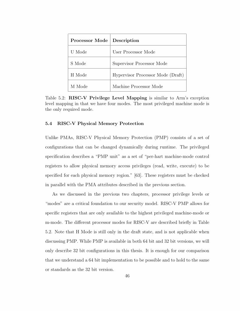
Processor Mode Description
U Mode User Processor Mode
S Mode Supervisor Processor Mode
H Mode Hypervisor Processor Mode (Draft)
M Mode Machine Processor Mode
Table 5.2: RISC-V Privilege Level Mapping is similar to Arm’s exceptionlevel mapping in that we have four modes. The most privileged machine mode isthe only required mode.
5.4 RISC-V Physical Memory Protection
Unlike PMAs, RISC-V Physical Memory Protection (PMP) consists of a set of
configurations that can be changed dynamically during runtime. The privileged
specification describes a “PMP unit” as a set of “per-hart machine-mode control
registers to allow physical memory access privileges (read, write, execute) to be
specified for each physical memory region.” [63]. These registers must be checked
in parallel with the PMA attributes described in the previous section.
As we discussed in the previous two chapters, processor privilege levels or
“modes” are a critical foundation to our security model. RISC-V PMP allows for
specific registers that are only available to the highest privileged machine-mode or
m-mode. The different processor modes for RISC-V are described briefly in Table
5.2. Note that H Mode is still only in the draft state, and is not applicable when
discussing PMP. While PMP is available in both 64 bit and 32 bit versions, we will
only describe 32 bit configurations in this thesis. It is enough for our comparison
that we understand a 64 bit implementation to be possible and to hold to the same
or standards as the 32 bit version.
46
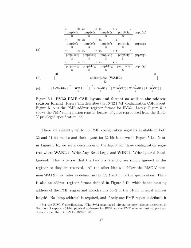
(a)
31 24 23 16 15 8 7 0
pmp3cfg pmp2cfg pmp1cfg pmp0cfg pmpcfg0
8 8 8 831 24 23 16 15 8 7 0
pmp7cfg pmp6cfg pmp5cfg pmp4cfg pmpcfg1
8 8 8 831 24 23 16 15 8 7 0
pmp11cfg pmp10cfg pmp9cfg pmp8cfg pmpcfg2
8 8 8 831 24 23 16 15 8 7 0
pmp15cfg pmp14cfg pmp13cfg pmp12cfg pmpcfg3
8 8 8 8
(b)31 0
address[33:2] (WARL)32
(c)7 6 5 4 3 2 1 0
L (WARL) WIRI A (WARL) X (WARL) W (WARL) R (WARL)1 2 2 1 1 1
Figure 5.1: RV32 PMP CSR layout and format as well as the addressregister format. Figure 5.1a describes the RV32 PMP configuration CSR layout.Figure 5.1b is the PMP address register format for RV32. Lastly, Figure 5.1cshows the PMP configuration register format. Figures reproduced from the RISC-V privileged specification [63].
There are currently up to 16 PMP configuration registers available in both
32 and 64 bit modes and their layout for 32 bit is shown in Figure 5.1a. Next,
in Figure 5.1c, we see a description of the layout for those configuration regis-
ters where WARL is Write-Any Read-Legal and WIRI is Write-Ignored Read-
Ignored. This is to say that the two bits 5 and 6 are simply ignored in this
register as they are reserved. All the other bits will follow the RISC-V com-
mon WARL field rules as defined in the CSR section of the specification. There
is also an address register format defined in Figure 5.1b, which is the starting
address of the PMP region and encodes bits 33–2 of the 34-bit physical address
length1. No “stop address” is required, and if only one PMP region is defined, it
1Per the RISC-V specification, “The Sv32 page-based virtual-memory scheme described inSection 4.3 supports 34-bit physical addresses for RV32, so the PMP scheme must support ad-dresses wider than XLEN for RV32.” [63].
47

will encompass the entire memory space. Indeed when many systems boot they
may choose to create a single PMP region with read/write/execute enabled for all
modes as a default setting.
The “L” bit of the configuration register defines if that region of memory is
locked and cannot be read, written, or executed from, regardless of the processor
mode. A reset is required for m-mode to once again control that CSR and allow
that region’s permissions to change. As mentioned, bits 6 and 5 are reserved. Bits
4 and 3 define the type of address matching scheme that will be used to match
the store or load address range against the PMP address register. The options
for this two bit value are OFF, Top of Range (TOR), Naturally Aligned 4-byte
region (NA4), or Naturally Aligned Power of Two (NAPOT). If set to NAPOT the
granularity can be set by the system to any NAPOT value greater than or equal to
8. The last three bits are set to 1 or 0 for read, write, and execute, with 1 meaning
“enabled” and 0 meaning “disabled”. These bits currently apply to both S Mode
and U Mode, though we will discuss the future of S Mode PMP in a following
section.
Using these configuration registers and address registers, RISC-V systems are
able to create regions of memory with simple read, write, and execute privileges
enforced by hardware. This allows systems to build secured areas of memory
similar to that of both Intel Software Guard Extensions (SGX) and Arm TrustZone.
However, without a framework on which to build these secured areas of memory,
the specification only enables hardware engineers to create a foundation on which
to build a Trusted Execution Environment (TEE). We will now examine Keystone
Enclave, an open source framework for building hardware TEEs using RISC-V
PMP as the foundation.
48
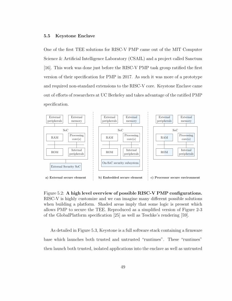
5.5 Keystone Enclave
One of the first TEE solutions for RISC-V PMP came out of the MIT Computer
Science & Artificial Intelligence Laboratory (CSAIL) and a project called Sanctum
[16]. This work was done just before the RISC-V PMP task group ratified the first
version of their specification for PMP in 2017. As such it was more of a prototype
and required non-standard extensions to the RISC-V core. Keystone Enclave came
out of efforts of researchers at UC Berkeley and takes advantage of the ratified PMP
specification.
RAM
ROMInternal
peripherals
Processingcore(s)
SoC
Externalmemory
Externalperipherals
External Security SoC
a) External secure element
RAM
ROMInternal
peripherals
Processingcore(s)
SoC
Externalmemory
Externalperipherals
On-SoC security subsystem
b) Embedded secure element
RAM
ROMInternal
peripherals
Processingcore(s)
SoC
Externalmemory
Externalperipherals
c) Processor secure environment
Figure 5.2: A high level overview of possible RISC-V PMP configurations.RISC-V is highly customize and we can imagine many different possible solutionswhen building a platform. Shaded areas imply that some logic is present whichallows PMP to secure the TEE. Reproduced as a simplified version of Figure 2-3of the GlobalPlatform specification [25] as well as Teschke’s rendering [59].
As detailed in Figure 5.3, Keystone is a full software stack containing a firmware
base which launches both trusted and untrusted “runtimes”. These “runtimes”
then launch both trusted, isolated applications into the enclave as well as untrusted
49
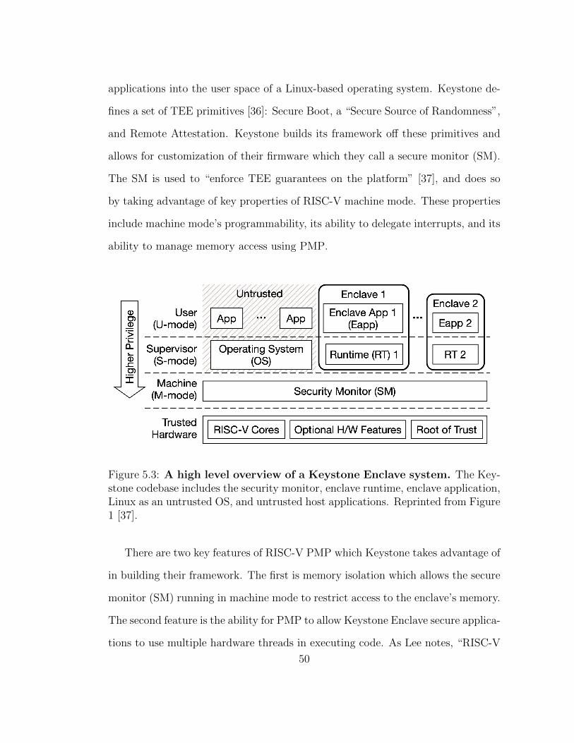
applications into the user space of a Linux-based operating system. Keystone de-
fines a set of TEE primitives [36]: Secure Boot, a “Secure Source of Randomness”,
and Remote Attestation. Keystone builds its framework off these primitives and
allows for customization of their firmware which they call a secure monitor (SM).
The SM is used to “enforce TEE guarantees on the platform” [37], and does so
by taking advantage of key properties of RISC-V machine mode. These properties
include machine mode’s programmability, its ability to delegate interrupts, and its
ability to manage memory access using PMP.
Figure 5.3: A high level overview of a Keystone Enclave system. The Key-stone codebase includes the security monitor, enclave runtime, enclave application,Linux as an untrusted OS, and untrusted host applications. Reprinted from Figure1 [37].
There are two key features of RISC-V PMP which Keystone takes advantage of
in building their framework. The first is memory isolation which allows the secure
monitor (SM) running in machine mode to restrict access to the enclave’s memory.
The second feature is the ability for PMP to allow Keystone Enclave secure applica-
tions to use multiple hardware threads in executing code. As Lee notes, “RISC-V
50
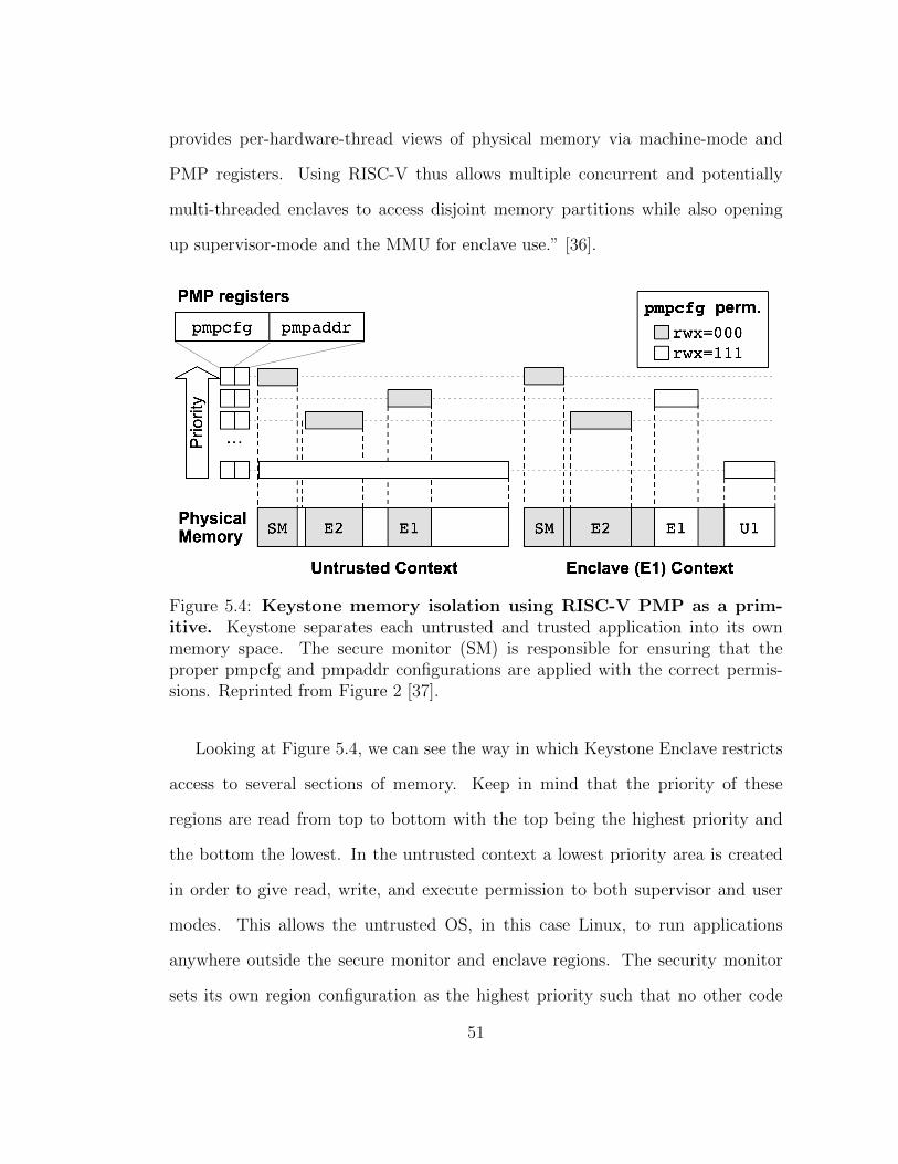
provides per-hardware-thread views of physical memory via machine-mode and
PMP registers. Using RISC-V thus allows multiple concurrent and potentially
multi-threaded enclaves to access disjoint memory partitions while also opening
up supervisor-mode and the MMU for enclave use.” [36].
Figure 5.4: Keystone memory isolation using RISC-V PMP as a prim-itive. Keystone separates each untrusted and trusted application into its ownmemory space. The secure monitor (SM) is responsible for ensuring that theproper pmpcfg and pmpaddr configurations are applied with the correct permis-sions. Reprinted from Figure 2 [37].
Looking at Figure 5.4, we can see the way in which Keystone Enclave restricts
access to several sections of memory. Keep in mind that the priority of these
regions are read from top to bottom with the top being the highest priority and
the bottom the lowest. In the untrusted context a lowest priority area is created
in order to give read, write, and execute permission to both supervisor and user
modes. This allows the untrusted OS, in this case Linux, to run applications
anywhere outside the secure monitor and enclave regions. The security monitor
sets its own region configuration as the highest priority such that no other code
51
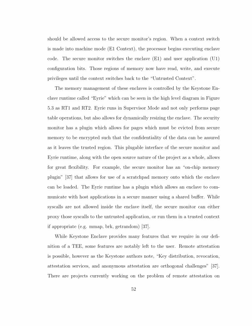
should be allowed access to the secure monitor’s region. When a context switch
is made into machine mode (E1 Context), the processor begins executing enclave
code. The secure monitor switches the enclave (E1) and user application (U1)
configuration bits. Those regions of memory now have read, write, and execute
privileges until the context switches back to the “Untrusted Context”.
The memory management of these enclaves is controlled by the Keystone En-
clave runtime called “Eyrie” which can be seen in the high level diagram in Figure
5.3 as RT1 and RT2. Eyrie runs in Supervisor Mode and not only performs page
table operations, but also allows for dynamically resizing the enclave. The security
monitor has a plugin which allows for pages which must be evicted from secure
memory to be encrypted such that the confidentiality of the data can be assured
as it leaves the trusted region. This plugable interface of the secure monitor and
Eyrie runtime, along with the open source nature of the project as a whole, allows
for great flexibility. For example, the secure monitor has an “on-chip memory
plugin” [37] that allows for use of a scratchpad memory onto which the enclave
can be loaded. The Eyrie runtime has a plugin which allows an enclave to com-
municate with host applications in a secure manner using a shared buffer. While
syscalls are not allowed inside the enclave itself, the secure monitor can either
proxy those syscalls to the untrusted application, or run them in a trusted context
if appropriate (e.g. mmap, brk, getrandom) [37].
While Keystone Enclave provides many features that we require in our defi-
nition of a TEE, some features are notably left to the user. Remote attestation
is possible, however as the Keystone authors note, “Key distribution, revocation,
attestation services, and anonymous attestation are orthogonal challenges” [37].
There are projects currently working on the problem of remote attestation on
52
RISC-V hardware [56], however these efforts are still in their infancy. Keystone
Enclaves provide a method of local attestation which makes use of provisioned keys.
Enclaves can, during runtime, request signed attestation from the secure monitor
in a kind of attestation report similar to that found in Sanctum [35]. This local
attestation is built off of a Secure Boot process that is very similar to TrustZone’s
model, and includes the use of hardware key management and cryptographic en-
gines. Efforts to continue work on secure boot RISC-V systems is the focus of
research [29], but no dominant technology currently exists as a de facto standard.
5.6 Future Extensions of RISC-V Memory Protection
Three additional features of RISC-V PMP will doubtless play a role in future work
done on Keystone Enclave or any RISC-V based TEE framework. The first is
a draft of an Extended Physical Memory Protection (ePMP) specification which
details how PMP will be able to secure user mode code from being executed by
machine mode. Attacking user mode from a more privileged mode is a well known
security vulnerability first address in Intel Ivy Bridge processors about a decade ago
[53]. Seagate recently announced their completion of a chip which takes advantage
of this draft ePMP features. The draft ePMP specification is currently supported
inside the Spike simulator, which is the de facto functional simulator for RISC-
V [7]. ePMP has also been implemented in open source hardware cores like the
Ibex core from lowRISC [39] as well as the open source Root of Trust (RoT)
OpenTitan [28].
The second additional feature, S-Mode Physical Memory Protection (sPMP),
is also in draft status as of this writing. sPMP will provide a way to ensure that
systems without virtual memory can take full advantage of PMP. Currently the
53
separation between S Mode and U Mode is done in virtual memory. This extension
will allow for PMP configuration registers specifically reserved for S Mode, moving
that protection from virtual memory into hardware registers. While sPMP is not
implemented yet in any simulators or publicly available hardware, sPMP will likely
see more development this year as the specification nears ratification.
The final additional feature, the draft specification for I/O Physical Memory
Protection (IOPMP), aims to provide memory protection for additional memory
masters such as Direct Memory Access (DMA). These memory masters will all
share one IOPMP unit that will allow for both single core and multi-cores sys-
tems, support error reporting, and support a scalable number of IOPMP entries.
The current draft specification defines an address table and IOPMP configuration
registers which provide address matching for each of the IOPMP addresses.
All three of these extensions, ePMP, sPMP, and IOPMP are in various stages
of ratification by RISC-V International. As such, their features are still in flux to
different degrees. However, ePMP, sPMP, and IOPMP show the direction that
RISC-V is heading in terms of TEE development as an attempt to provide as many
if not more features than currently available TEE technologies.
We have now covered three different implementations of a Trusted Execution
Environment (TEE). These high level descriptions will act as a general reference in
the next chapter where we will provide a method for comparing these technologies.
The method we present can be applied to any set of TEEs regardless of their
complexity or their intended target hardware. The three examples of a TEE have
provided a foundation for the systematic and rigorous comparison that will be
detailed in the following chapter.
54
Chapter 6
Trusted Execution Environment Comparisons
6.1 A Method for Comparing TEEs
When we compare Intel Software Guard Extensions (SGX), Arm TrustZone, RISC-
V Physical Memory Protection (PMP), or any group of Trusted Execution Envi-
ronments (TEEs) we must first consider what we are comparing. As such we define
any given TEE based on a set of properties that the TEE must implement or op-
tionally might implement. We will make the assumption that the end goal of the
comparison is to choose a TEE that best meets the needs of the system architect.
As such, we must take the system architect’s needs into consideration in choos-
ing which properties that we will compare. An architect designing an embedded
system with no access to networking will certainly not require traditional remote
attestation, as an example.
As mentioned in Chapter 1, we will use the properties of a TEE as defined by
the Confidential Computing Consortium (CCC) [58]. The CCC is an open source
project that brings together hardware vendors, cloud providers, and software devel-
opers to accelerate the adoption of TEE technologies and standards. They define
code integrity, data integrity, and data confidentiality as three required properties
of any hardware TEE. All three of the TEE technologies which we have summa-
rized in the preceding chapters provide these three required features in different
ways. The CCC also discusses more advanced features like code confidentiality,
authenticated launch, programmability, attestation, and recoverability, which can
be considered optional properties of a TEE. As a final option of a TEE, we will
55
include extensibility, which will be discussed in detail shortly.
Notably absent from our list of required properties is code confidentiality. There
are several reasons why one might want code to be confidential. Code may contain
proprietary algorithms for machine learning or other intellectual property. Likewise
code may contain information about health or safety systems which must remain
confidential to assure functional safety. On the other hand, the code that runs
inside the TEE may be open source, making the feature of code confidentiality
nonessential. As such, code confidentiality is considered an optional property by
our definition.
By authenticated launch, we mean a mechanism by which the TEE can prevent
a host application from loading, or limit its functionality based on a set of criteria
or security model. One can think of this in terms of a banking application on a
cell phone. If any stage of the attestation process fails, we want to recognize that
code integrity can no longer be assured. We may want to fail to load the banking
application with appropriate errors if code integrity is compromised. However,
we may want some of the features of the banking application available, while
restricting others. Authenticated launch may restrict withdrawing funds from an
account while allowing the application to provide text messaging with technical
support in order to resolve the problem.
By programmability, we mean the ability of a TEE to be programmed with
code that is unrestricted and able to be changed by the end user. This is apposed
to a TEE with a limited set of available functions or one that is pre-programmed by
the manufacturer or system vendor. Programmability will be limited by the type
of instructions which are allowed to be executed from inside the TEE. The size of
the region of code that is allowed to be used by the TEE may also be restricted.
56
Lastly, the way in which code running inside the TEE is allowed to communicate
with code running outside the TEE is also a consideration of programmability. We
will consider a TEE programmable to different degrees based on these limitations.
By attestation, we will use the definition by the CCC provided in Section
6 of their paper [58]. The attestation workflow starts with a secure connection
between the two parties, identified as the verifier and the attester. The verifier
must first challenge the attester to initiate the check. The challenge from the
verifier signals to the attester that it must communicate with trusted hardware
to request a measurement of the TEE. The trusted hardware is responsible for
the measurement value as well as any certification of origin. The attester can
then return these values to the verifier. The verifier will check any signatures
provided based on the security model. Attestation may be performed locally on
the host machine. If the verifier is on a remote machine to that of the attester we
would consider that to be remote attestation. Attestation should take advantage
of a Root of Trust (RoT), however that root of trust may be either hardware or
software based. If a given system contains a hardware RoT we can consider that
system more secure by the same definition we gave earlier of a hardware TEE.
By recoverability, we mean a way for the TEE to “roll back” to some known
good state should a failure occur while preforming validation on the integrity or
confidentiality of the system. The goal of recoverability is to re-establish trust in
the Trusted Compute Base (TCB). Part of the TCB may not be easily recoverable.
For example, if the platform firmware loaded onto an Intel SGX system is found
to be untrustworthy, a simple firmware update may not be capable of removing
malicious code. However, if the code running inside the SGX enclave is found to be
untrustworthy, simply reloading that code from its original source may be enough
57
to reliably restore trust in the application.
Finally, we add extensibility as the final optional property of a TEE. Extensi-
bility was not defined in the CCC document, however extensibility can be observed
to some extent in all three TEE technologies we have covered. We define exten-
sibility as the ability to customize the deployment and management of the TEE
environment, including hardware, firmware, and software. This property comes
at the cost of supporting those customizations. As Linus’s Law states, “Given
enough eyeballs, all bugs are shallow” [52]. Regardless, the burden of support for
customization must be a consideration, and a healthy open source project is no
small feat.
While these properties are a good starting point for analysis and comparison,
we must break these properties down further in order to engage in a more rigorous
comparison. Authenticated launch can be broken up into two parts: the ability
to prevent application launch, or the ability to launch applications with limited
functionality. Programmability will be broken into three types: the size available to
the TCB, the number of unique trusted applications one can run, and the number
trusted OS’s one can run to manage these applications. Attestation can be divided
into three parts, with remote attestation, local attestation, and if a hardware root
of trust is available. Recoverability will be divided into three parts describing
system which allow: revocation of keys or other components, ability to recover
the TCB using a hardware RoT, and finally if re-issuing keys is possible without
the need for re-provisioning. Extensibility will be broken up into three parts:
hardware, firmware, and software. We will consider the levels of extensibility as
either “highly extensible”, “somewhat extensible”, or “not extensible”.
58
6.2 Mapping Data Points
This method uses tables to chart the comparison of these properties and sub-
properties we have discussed. In the following Tables 6.1, 6.2, and 6.3, we give
example tables for the three technologies discussed in the previous chapters. The
first Table 6.1 covers all six of the optional properties of a TEE that we have
discussed in this chapter. Rather than grading each implementation of the property
in a simple “good, better, best” fashion, we list if the property is possible in the
given solution, and if so, the dependency of that property. Next, in Tables 6.2
and 6.3, we pick two of the optional properties of a TEE and divide them into the
smaller pieces we mentioned in the previous section. A more rigorous comparison
can then be made on the details of each property.
This thesis only breaks down two of the optional properties of a TEE into
greater detailed tables. It is left up to the reader to continue this process for the
additional properties. Also, as a reminder to the reader, the data provided in this
thesis can and will change drastically over time. All of the following tables are
meant as examples to the process of comparison and should not be considered as
complete and wholly valid data sources.
Noting that the optional property of a TEE is available and listing required
dependencies is helpful, however we also make a point to parenthetically note an
example dependency where applicable. At the highest level, as in Table 6.1, this
can be quite broad indeed. For example, attestation is possible with TrustZone and
is provided locally by firmware or remotely by SoC manufacturers like Qualcomm.
This is further illustrated in Table 6.2, where we show that local attestation can
be achieved merely by using the appropriate firmware, however to achieve remote
attestation, a system like Qualcomm’s MSM8974 Snapdragon-based platform is
59

required [57]. Again, note that we are using quite an old example with Qualcomm’s
MSM8974, circa 2016. Readers wishing to implement this method of comparison
would be wise to chose current security platforms. Likewise, we list Intel as the
only current solution to providing remote attestation for SGX solutions, however
it is highly likely that other solutions are available.
The final Table 6.3 compares extensibility and requires we provide context. The
table works from high level features like the Software Development Kit (SDK), to
low level features like the actual HDL used to generate the TEE. As mentioned
earlier, extensibility does not require that the system in question be open source.
However, since open source options exist, and those systems are inherently exten-
sible, we have listed those where possible. To say that the firmware is open source
and therefore extensible does not provide enough explanation, and we should be
more precise with our definition. Looking at TrustZone, the trusted OS provided
by Open-source Portable TEE (OP-TEE) and secure boot provided by Trusted
Firmware-A (TF-A) allow a high level of customization and extension. Likewise
the Keystone project allows developers to extend its feature set with a set of “plu-
gable interfaces” [37]. While Intel and others have worked to provide open source
and extensible firmware for their platforms, the goal of those firmware projects
is not to provide systems with a way to extend the features provided by Intel
SGX. Therefore, while firmware available for SGX is indeed open source, it is not
specifically designed with extensibility for SGX in mind.
As mentioned earlier, extensible systems as described in Table 6.3 may lack
vendor-supplied support options. While Intel systems may seem like the more
ridged of the three options, Intel aims to provide a high level of support for their
60
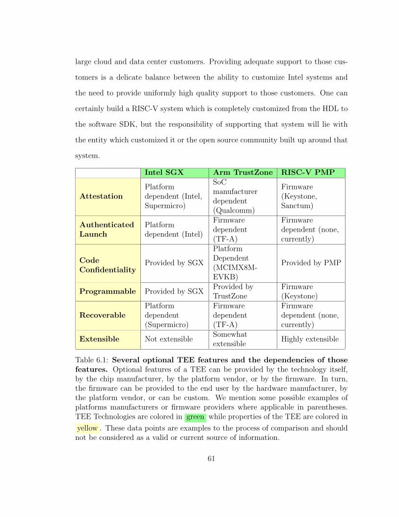
large cloud and data center customers. Providing adequate support to those cus-
tomers is a delicate balance between the ability to customize Intel systems and
the need to provide uniformly high quality support to those customers. One can
certainly build a RISC-V system which is completely customized from the HDL to
the software SDK, but the responsibility of supporting that system will lie with
the entity which customized it or the open source community built up around that
system.
Intel SGX Arm TrustZone RISC-V PMP
AttestationPlatformdependent (Intel,Supermicro)
SoCmanufacturerdependent(Qualcomm)
Firmware(Keystone,Sanctum)
AuthenticatedLaunch
Platformdependent (Intel)
Firmwaredependent(TF-A)
Firmwaredependent (none,currently)
CodeConfidentiality
Provided by SGX
PlatformDependent(MCIMX8M-EVKB)
Provided by PMP
Programmable Provided by SGXProvided byTrustZone
Firmware(Keystone)
RecoverablePlatformdependent(Supermicro)
Firmwaredependent(TF-A)
Firmwaredependent (none,currently)
Extensible Not extensibleSomewhatextensible
Highly extensible
Table 6.1: Several optional TEE features and the dependencies of thosefeatures. Optional features of a TEE can be provided by the technology itself,by the chip manufacturer, by the platform vendor, or by the firmware. In turn,the firmware can be provided to the end user by the hardware manufacturer, bythe platform vendor, or can be custom. We mention some possible examples ofplatforms manufacturers or firmware providers where applicable in parentheses.TEE Technologies are colored in green while properties of the TEE are colored in
yellow . These data points are examples to the process of comparison and shouldnot be considered as a valid or current source of information.
61
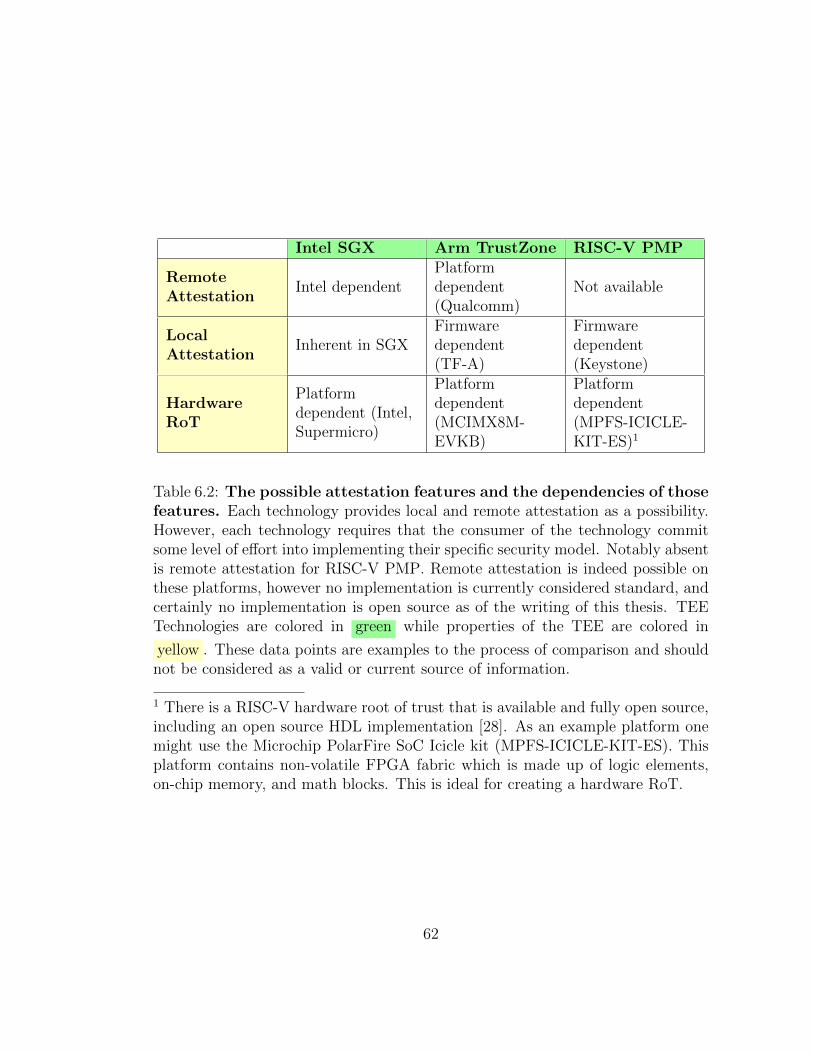
Intel SGX Arm TrustZone RISC-V PMP
RemoteAttestation
Intel dependentPlatformdependent(Qualcomm)
Not available
LocalAttestation
Inherent in SGXFirmwaredependent(TF-A)
Firmwaredependent(Keystone)
HardwareRoT
Platformdependent (Intel,Supermicro)
Platformdependent(MCIMX8M-EVKB)
Platformdependent(MPFS-ICICLE-KIT-ES)1
Table 6.2: The possible attestation features and the dependencies of thosefeatures. Each technology provides local and remote attestation as a possibility.However, each technology requires that the consumer of the technology commitsome level of effort into implementing their specific security model. Notably absentis remote attestation for RISC-V PMP. Remote attestation is indeed possible onthese platforms, however no implementation is currently considered standard, andcertainly no implementation is open source as of the writing of this thesis. TEETechnologies are colored in green while properties of the TEE are colored in
yellow . These data points are examples to the process of comparison and shouldnot be considered as a valid or current source of information.
1 There is a RISC-V hardware root of trust that is available and fully open source,including an open source HDL implementation [28]. As an example platform onemight use the Microchip PolarFire SoC Icicle kit (MPFS-ICICLE-KIT-ES). Thisplatform contains non-volatile FPGA fabric which is made up of logic elements,on-chip memory, and math blocks. This is ideal for creating a hardware RoT.
62
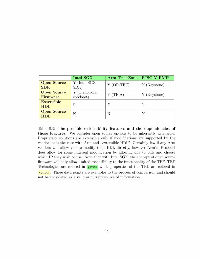
Intel SGX Arm TrustZone RISC-V PMPOpen SourceSDK
Y (Intel SGXSDK)
Y (OP-TEE) Y (Keystone)
Open SourceFirmware
Y (TianoCore,coreboot)
Y (TF-A) Y (Keystone)
ExtensibleHDL
N Y Y
Open SourceHDL
N N Y
Table 6.3: The possible extensibility features and the dependencies ofthose features. We consider open source options to be inherently extensible.Proprietary solutions are extensible only if modifications are supported by thevendor, as is the case with Arm and “extensible HDL”. Certainly few if any Armvendors will allow you to modify their HDL directly, however Arm’s IP modeldoes allow for some inherent modification by allowing one to pick and choosewhich IP they wish to use. Note that with Intel SGX, the concept of open sourcefirmware will only allow limited extensibility to the functionality of the TEE. TEETechnologies are colored in green while properties of the TEE are colored in
yellow . These data points are examples to the process of comparison and shouldnot be considered as a valid or current source of information.
63
6.3 Considerations and Limitations
In this comparison we have not distinguished between platform manufacturers and
platforms vendors. As an example, Supermicro is a platform manufacturer which
might produce a platform based on an Intel Xeon Processor currently code named
“Ice Lake-SP” which will support SGX on multi-socket systems. They might then
sell those platforms to a vendor like Hewlett Packard or Dell. How Intel SGX
will function on these platforms becomes a combination of the instructions Intel
has added to the architecture, the workflow inherent in the microarchitecture, how
the chipset is assembled, how Supermicro assembled that chipset into a platform,
and how HP or Dell supports that platform with firmware, software, and possibly
remote attestation services. The same is true of Arm systems and RISC-V systems.
One quickly sees the complexity of securing systems in the real world. Our method
for comparison is meant only as a high level tool for assessing the appropriateness
of a TEE technology to a use case.
The method we have described will also be limited by the scope of the use case.
The complexity of the comparison will grow in a linear manner to the complexity
of the use case. One can quickly postulate that a multi-party system based on
heterogeneous TEEs will reach levels of complexity such that this method begins
to break down, or at the very least requires much more rigor than the simple
comparisons shown here. This method is submitted not as a golden standard for
comparison, but rather as a baseline on which further research may provide avenues
for comparison not imagined in this thesis.
64
Chapter 7
Conclusion
This thesis has described a method that allows for a comprehensive and rigorous
comparison of Trusted Execution Environments (TEEs). This method involves
identifying the properties of interest for hardware architects, firmware authors,
and TEE software designers alike. Key to our comparison of the implementations
of those properties is breaking each property down into relevant constituent parts.
The relevancy of each property will depend on the use case of the designer, and
should be taken into account during comparison. This method does not provide
us with which technology is the “best,” but rather gives us insight into which TEE
might best fit a specific set of needs.
There are several use cases for systems requiring a TEE that this thesis does
not take into account. These use cases could be the subject of future work in
improving this methodology. Multi-socket processors [34] add another layer of
complexity to TEEs and should be considered for cloud compute or data center
use cases. Likewise systems might require multiple TEEs or heterogeneous TEE
environments, perhaps for enhanced security use cases. As an example, a system
running both TrustZone alongside RISC-V Physical Memory Protection (PMP)
may require communication between these different TEEs to assure secure com-
putation. Examining the details of how these systems are able to interact and
communicate allows for new avenues of comparison. Future work covering these
use cases would add to the rigorous nature of this method.
This proposed method will save hardware architects the frustration that comes
65
with a wide range of technology choices. The method provides an organizational
framework for characterizing properties of a TEE and provides value to product
designers who must focus on possible use cases ranging from mobile devices to cloud
services. It is possible that this method may be insufficient for some future version
of a TEE, as evidenced by how new technologies like RISC-V Physical Memory
Protection (PMP) are both mimicking older technologies as well as developing
new and innovative features. However, as the use of TEEs becomes more common
and these technologies take on new unique properties, it is likely that these new
properties will be easily integrated into this method of comparison.
66
References
[1] I. Anati, S. Gueron, S. Johnson, and V. Scarlata, “Innovative technology
for CPU based attestation and sealing,” in Proceedings of the 2nd interna-
tional workshop on hardware and architectural support for security and pri-
vacy, vol. 13. ACM New York, NY, USA, 2013, p. 7.
[2] P. Anemaet and T. van As, “Microprocessor soft-cores: An evaluation of
design methods and concepts on FPGAs,” part of the Computer Architecture
(Special Topics) course ET4078, Department of Computer Engineering, 2003.
[3] Arm Limited, “Arm Security Technology Building a Secure System using
TrustZone Technology, Issue C,” Arm Limited, Tech. Rep., April 2009.
[4] ——, “Fundamentals of ARMv8-A Version 1.0,” Arm Limited, Tech. Rep.,
March 2015.
[5] ——, “Trusted Base System Architecture, Client, Version F,” Arm Limited,
Tech. Rep., August 2020.
[6] Arm Limited, Architecture and Technology Group, “Trusted Board Boot Re-
quirements CLIENT (TBBR-CLIENT) ARMv8-A, Version 1.0,” Arm Lim-
ited, Tech. Rep., September 2018.
[7] K. Asanovic, R. Avizienis, J. Bachrach, S. Beamer, D. Biancolin, C. Celio,
H. Cook, D. Dabbelt, J. Hauser, A. Izraelevitz et al., “The rocket chip gen-
erator,” EECS Department, University of California, Berkeley, Tech. Rep.
UCB/EECS-2016-17, 2016.
67
[8] K. Asanovic and D. A. Patterson, “Instruction sets should be free: The case
for RISC-V,” EECS Department, University of California, Berkeley, Tech.
Rep. UCB/EECS-2014-146, 2014.
[9] J. G. Beekman, “Improving cloud security using secure enclaves,” Ph.D. dis-
sertation, UC Berkeley, 2016.
[10] T. Bourgeat, I. Lebedev, A. Wright, S. Zhang, and S. Devadas, “Mi6: Secure
enclaves in a speculative out-of-order processor,” in Proceedings of the 52nd
Annual IEEE/ACM International Symposium on Microarchitecture, 2019, pp.
42–56.
[11] E. Brickell and J. Li, “Enhanced privacy ID: A direct anonymous attestation
scheme with enhanced revocation capabilities,” in Proceedings of the 2007
ACM workshop on Privacy in electronic society, 2007, pp. 21–30.
[12] G. Cabodi, P. Camurati, C. Loiacono, G. Pipitone, F. Savarese, and D. Ven-
draminetto, “Formal verification of embedded systems for remote attestation,”
WSEAS Transactions on Computers, vol. 14, pp. 760–769, 2015.
[13] S. Chakrabarti, M. Hoekstra, D. Kuvaiskii, and M. Vij, “Scaling Intel
Software Guard Extensions Applications with Intel SGX Card,” in
Proceedings of the 8th International Workshop on Hardware and Architectural
Support for Security and Privacy, ser. HASP ’19. New York, NY,
USA: Association for Computing Machinery, 2019. [Online]. Available:
https://doi.org/10.1145/3337167.3337173
68
[14] K. Cheang, C. Rasmussen, D. Lee, D. W. Kohlbrenner, K. Asanovic, and
S. A. Seshia, “Verifying RISC-V physical memory protection,” IEEE Inter-
national Symposium on Performance Analysis of Systems and Software (IS-
PASS) Workshop on Secure RISC-V Architecture Design, August 2020.
[15] V. Costan and S. Devadas, “Intel SGX Explained,” International Association
for Cryptologic Research ePrint Archive, pp. 1–118, 2016. [Online]. Available:
http://eprint.iacr.org/2016/086
[16] V. Costan, I. Lebedev, and S. Devadas, “Sanctum : Minimal Hardware
Extensions for Strong Software Isolation This paper is included in
the Proceedings of the Sanctum : Minimal Hardware Extensions for
Strong Software Isolation,” Usenix, vol. 25, pp. 857–874, 2016. [Online].
Available: https://www.usenix.org/conference/usenixsecurity16/technical-
sessions/presentation/costan
[17] M. Da Silva, “Securing a trusted hardware environment (trusted execution
environment),” Ph.D. dissertation, Universite Montpellier, 2018.
[18] B. Delgado and K. L. Karavanic, “Performance implications of system man-
agement mode,” in 2013 IEEE International Symposium on Workload Char-
acterization (IISWC), 2013, pp. 163–173.
[19] D. Eldar, A. Kumar, and P. Goel, “Configuring Intel active management
technology.” Intel Technology Journal, vol. 12, no. 4, 2008.
[20] K. Eldefrawy, N. Rattanavipanon, and G. Tsudik, “Hydra: hybrid design for
remote attestation (using a formally verified microkernel),” in Proceedings of
69
the 10th ACM Conference on Security and Privacy in wireless and Mobile
Networks, 2017, pp. 99–110.
[21] T. Garfinkel, B. Pfaff, J. Chow, M. Rosenblum, and D. Boneh, “Terra: A
virtual machine-based platform for trusted computing,” in Proceedings of the
nineteenth ACM symposium on Operating systems principles, 2003, pp. 193–
206.
[22] C. Gentry, “A fully homomorphic encryption scheme,” Ph.D. dissertation,
Stanford University, Stanford, CA, USA, 2009.
[23] GlobalPlatform Inc, “GlobalPlatform TEE Client API Specification Version
1.0,” 07 2010.
[24] ——, “GlobalPlatform TEE Client API Specification Version 1.0,” 07 2010.
[25] ——, “GlobalPlatform Technology TEE System Architecture Version 1.2,” 11
2018.
[26] ——, “GlobalPlatform TEE Internal Core API Specification Version 1.2.1,”
05 2019.
[27] ——, “GlobalPlatform TEE Protection Profile Version 1.3,” 09 2020.
[28] S. Guilley, M. Le Rolland, and D. Quenson, “Implementing secure applications
thanks to an integrated secure element,” in 7th International Conference on
Information Systems Security and Privacy, 2021.
[29] J. Haj-Yahya, M. M. Wong, V. Pudi, S. Bhasin, and A. Chattopadhyay,
“Lightweight secure-boot architecture for RISC-V system-on-chip,” in 20th
70
International Symposium on Quality Electronic Design (ISQED). IEEE,
2019, pp. 216–223.
[30] M. Hoekstra, R. Lal, P. Pappachan, V. Phegade, and J. Del Cuvillo,
“Using innovative instructions to create trustworthy software solutions,”
in Proceedings of the 2nd International Workshop on Hardware and
Architectural Support for Security and Privacy, ser. HASP ’13. New York,
NY, USA: Association for Computing Machinery, 2013. [Online]. Available:
https://doi.org/10.1145/2487726.2488370
[31] S. Johnson, V. Scarlata, C. Rozas, E. Brickell, and F. Mckeen, “Intel software
guard extensions: EPID provisioning and attestation services,” White Paper,
vol. 1, no. 1-10, p. 119, 2016.
[32] S. P. Johnson, U. R. Savagaonkar, V. R. Scarlata, F. X. McKeen, and C. V.
Rozas, “Technique for supporting multiple secure enclaves,” Dec. 2010, US
Patent 8,972,746.
[33] P. A. Karger and A. J. Herbert, “An augmented capability architecture to
support lattice security and traceability of access,” in 1984 IEEE Symposium
on Security and Privacy, 1984, pp. 2–2.
[34] T. Knauth, M. Steiner, S. Chakrabarti, L. Lei, C. Xing, and M. Vij, “In-
tegrating remote attestation with transport layer security,” arXiv preprint
arXiv:1801.05863, 2018.
[35] I. Lebedev, K. Hogan, and S. Devadas, “Secure boot and remote attestation
in the sanctum processor,” in 2018 IEEE 31st Computer Security Foundations
Symposium (CSF). IEEE, 2018, pp. 46–60.
71
[36] D. Lee, D. Kohlbrenner, S. Shinde, K. Asanovic, and D. Song, “Keystone: An
open framework for architecting trusted execution environments,” in Proceed-
ings of the Fifteenth European Conference on Computer Systems, 2020, pp.
1–16.
[37] D. Lee, D. Kohlbrenner, S. Shinde, D. Song, and K. Asanovic, “Keystone:
A Framework for Architecting TEEs,” CoRR, vol. abs/1907.10119, 2019.
[Online]. Available: http://arxiv.org/abs/1907.10119
[38] Linaro Limited. Trusted Firmware. [Online]. Available: https:
//www.trustedfirmware.org
[39] lowRISC. Ibex Core. [Online]. Available: https://github.com/lowRISC/ibex
[40] D. W. Manchala, “Trust metrics, models and protocols for electronic com-
merce transactions,” in Proceedings. 18th International Conference on Dis-
tributed Computing Systems (Cat. No.98CB36183), 1998, pp. 312–321.
[41] F. X. McKeen, C. V. Rozas, U. R. Savagaonkar, S. P. Johnson, V. Scarlata,
M. A. Goldsmith, E. Brickell, J. T. Li, H. C. Herbert, P. Dewan et al., “Method
and apparatus to provide secure application execution,” Dec. 2009, US Patent
9,087,200.
[42] F. McKeen, I. Alexandrovich, A. Berenzon, C. V. Rozas, H. Shafi,
V. Shanbhogue, and U. R. Savagaonkar, “Innovative instructions and
software model for isolated execution,” in Proceedings of the 2nd International
Workshop on Hardware and Architectural Support for Security and Privacy,
ser. HASP ’13. New York, NY, USA: Association for Computing Machinery,
2013. [Online]. Available: https://doi.org/10.1145/2487726.2488368
72

[43] M. Nauman, S. Khan, X. Zhang, and J.-P. Seifert, “Beyond kernel-level in-
tegrity measurement: enabling remote attestation for the android platform,”
in International Conference on Trust and Trustworthy Computing. Springer,
2010, pp. 1–15.
[44] B. Ngabonziza, D. Martin, A. Bailey, H. Cho, and S. Martin, “TrustZone
explained: Architectural features and use cases,” in 2016 IEEE 2nd Interna-
tional Conference on Collaboration and Internet Computing (CIC), 2016, pp.
445–451.
[45] Open Mobile Terminal Platform, “OMTP: Advanced Trusted Environment:
OMTP TR1,” Open Mobile Terminal Platform, Tech. Rep., 01 2009.
[46] T. O’Reilly, “Lessons from open-source software development,” Communica-
tions of the ACM, vol. 42, no. 4, pp. 32–37, 1999.
[47] J. D. Osborn and D. C. Challener, “Trusted platform module evolution,”
Johns Hopkins APL Technical Digest (Applied Physics Laboratory), vol. 32,
no. 2, pp. 536–543, 2013.
[48] S. Perez. WAC Whacked: Telecom-Backed Alliance Merges Into GSMA,
Assets Acquired By API Management Service Apigee. [Online]. Available:
https://techcrunch.com/2012/07/17/wac-whacked-telecom-backed-alliance-
merges-into-gsma-assets-acquired-by-api-management-service-apigee
[49] A. S. Perrin, “The general data protection regulation and open source software
communities,” Cybaris®: Vol. 12 : Iss. 1 , Article 3, 2021.
[50] S. Pinto and J. Martins, “The industry-first secure IoT stack for RISC-V: a
research project,” in RISC-V Workshop,(Zurich), 2019.73
[51] S. Pinto and N. Santos, “Demystifying Arm TrustZone: A Comprehensive
Survey,” ACM Computing Surveys, vol. 51, no. 6, 2019.
[52] E. Raymond, “The cathedral and the bazaar,” Knowledge, Technology & Pol-
icy, vol. 12, no. 3, pp. 23–49, 1999.
[53] D. M. Rodriguez, D. H. Aristizabal, and R. Y. Guevara, “A primer to the
token stealing technique,” in 2013 47th International Carnahan Conference
on Security Technology (ICCST), 2013, pp. 1–3.
[54] M. Sabt, M. Achemlal, and A. Bouabdallah, “Trusted execution environment:
What it is, and what it is not,” in 2015 IEEE Trustcom/BigDataSE/ISPA,
vol. 1, 2015, pp. 57–64.
[55] M. Schwarz, S. Weiser, and D. Gruss, “Practical enclave malware with Intel
SGX,” in International Conference on Detection of Intrusions and Malware,
and Vulnerability Assessment. Springer, 2019, pp. 177–196.
[56] C. Shepherd, K. Markantonakis, and G.-A. Jaloyan, “LIRA-V: Lightweight
remote attestation for constrained RISC-V devices,” arXiv preprint
arXiv:2102.08804, 2021.
[57] C. Spensky, J. Stewart, A. Yerukhimovich, R. Shay, A. Trachtenberg, R. Hous-
ley, and R. K. Cunningham, “Sok: Privacy on mobile devices–it’s compli-
cated,” Proceedings on Privacy Enhancing Technologies, vol. 2016, no. 3, pp.
96–116, 2016.
[58] Technical Advisory Council, “A Technical Analysis of Confidential Computing
Version 1.1,” Confidential Computing Consortium, Tech. Rep., 01 2021.
74

[59] F. Teschke, “Hardening Applications with Intel SGX,” Master’s thesis, Hasso-
Plattner-Institut at the University of Potsdam, Prof.-Dr.-Helmert-Straße 2-3,
14482 Potsdam, Germany, June 2017, Anwendungen harten mit Intel SGX.
[60] UEFI Forum, “Unified Extensible Firmware Interface (UEFI) Specification
Version 2.8 Errata B,” May 2020.
[61] R. Uhlig, G. Neiger, D. Rodgers, A. L. Santoni, F. C. Martins, A. V. Anderson,
S. M. Bennett, A. Kagi, F. H. Leung, and L. Smith, “Intel virtualization
technology,” Computer, vol. 38, no. 5, pp. 48–56, 2005.
[62] A. Waterman and K. Asanovic, “The RISC-V Instruction Set Manual,
Volume I: User-Level ISA, Document Version 20191213,” RISC-V ISA,
vol. I, 2019. [Online]. Available: https://github.com/riscv/riscv-isa-manual/
releases/download/Ratified-IMAFDQC/riscv-spec-20191213.pdf
[63] ——, “The RISC-V Instruction Set Manual, Volume II: Privileged
Architecture, Document Version 20190608,” RISC-V ISA, vol. II, 2019.
[Online]. Available: https://github.com/riscv/riscv-isa-manual/releases/
download/Ratified-IMFDQC-and-Priv-v1.11/riscv-privileged-20190608.pdf
[64] N. Weichbrodt, A. Kurmus, P. Pietzuch, and R. Kapitza, “AsyncShock: Ex-
ploiting synchronisation bugs in Intel SGX enclaves,” in European Symposium
on Research in Computer Security. Springer, 2016, pp. 440–457.
[65] S. Weiser, M. Werner, F. Brasser, M. Malenko, S. Mangard, and A.-R.
Sadeghi, “TIMBER-V: Tag-isolated memory bringing fine-grained enclaves
to RISC-V.” in NDSS, 2019.
75
[66] J. Yao, V. J. Zimmer, and Q. Long, “System management mode isolation in
firmware,” May 7 2009, US Patent App. 12/317,446.
[67] V. Zimmer, “Hardened extensible firmware framework to support system man-
agement mode operations using 64-bit extended memory mode processors,”
May 26 2005, US Patent App. 10/971,824.
[68] V. Zimmer, M. Rothman, and S. Marisetty, Beyond BIOS: Developing with
the Unified Extensible Firmware Interface, Third Edition, 3rd ed. Berlin,
DEU: De|G Press, 2017.
[69] V. J. Zimmer, M. Kumar, M. Natu, Q. Long, L. Cui, and J. Yao, “Apparatus
and method for secure boot environment,” Jul. 19 2011, US Patent 7,984,286.
76