a method to design blended rolled edges compact range … · a method to design blended rolled...
TRANSCRIPT

A Method to Design Blended Rolled Edges for Compact Range Reflectors
Inder J. Gupta and Walter D. Burnside
The Ohio State University
ElectroScience laboratory Deportment of Electrical Engineering
Columbus, Ohio 43212
Technical Report 719493-6 Grant No. NSG 1613
March 1989
National Aeronautics and Space Administration Langley Research Center
Hampton, VA 22217
(NASI-CR-784976) JCLLEC EDGES F O E C C 8 ! I ; I C I 6 A 1 C E GIELLCTCRS A CIE2BOI) I'C L E S l G Y BLENDBD
C S C L 138 ( cb io S t a t e O t i v , ) '4; E
N89-23735
Uaclas 63/31 0209824
https://ntrs.nasa.gov/search.jsp?R=19890014365 2019-03-25T12:13:44+00:00Z
NOTICES
When Government drawings, spec i f i ca t i ons , o r o ther data are used f o r any purpose o the r than i n connection w i t h a d e f i n i t e l y r e l a t e d Government procurement operat ion, t he Uni ted States Government thereby incurs no r e s p o n s i b i l i t y nor any o b l i g a t i o n whatsoever, and the f a c t t h a t the Government may have formulated, furnished, o r i n any way suppl ied the sa id drawings, spec i f i ca t i ons , o r o ther data, i s no t t o be regarded by i m p l i c a t i o n o r otherwise as i n any manner l i c e n s i n g the ho lder o r any o ther person o r corporat ion, o r conveying any r i g h t s o r permission t o manufacture, use, o r s e l l any patented i nven t ion t h a t may i n any way be r e l a t e d there to .
.

I E I
REPORT DOCUMENTATION 1. REPORT NO. PAGE
1.
A Method to Desim Blended Rolled Edges for Compact Range Reflectors
18. Availability Statement 19. Security Clus (Thim Report)
t o . Security Clus (Thim Page) Unclassified
unclassified
'1. Author(@)
31. No. of Pages 37
31. Price
Inder J. Gupta and Walter D. Burnside
The Ohio State University ElectroScience Laboratory 1320 Kinnear Road Columbus. OH 43212
9. Performing Organisation Name and Address
~ ~ ~
11. Sponsoring Organisation Name and Address
National Aeronautics and Space Administration Langley Research Center Hampton, VA 23665
16. Supplementary Notes
l. Recipient's Accession No.
6. Report Date March 1989
6.
8. Performing Org. Rapt. No.
719493-6 10. ProJect/Tuk/Work Unit No.
11. Contract(C) or Grant(G) No.
(C)
(0) NSG-16ll 18. Report Type/Period Covered
Technical Report 14.
16. Abstract (Limit: 100 words)
A method to design blended rolled edges for arbitrary rim shape compact range reflectors is pre- sented. The reflectors may be center-fed or offset-fed. The method leads to rolled edges with mini- mal surface discontinuities. It is shown that the reflectors designed using the prescribed method can be defined analytically using simple expressions. A procedure to obtain optimum rolled edges pa- rameter is also presented. The procedure leads to blended rolled edges that minimize the diffracted fields emanating from the junction between the paraboloid and the rolled edge surface while eatis- fying certain constraints regarding the reflector size and the minimum operating frequency of the system.
17. Document Analysis a. Descdptors
b. Identiflerr/Open-Ended Terms
(See ANSI-Zl9.18) OPTIONAL FORM a71 (4-77) Department of Commerce

Contents LIST OF FIGURES
SECTION
iv
PAGE
INTRODUCTION 1
BLENDED ROLLED EDGE CONCEPT 4
METHOD TO SELECT THE ROLLED EDGE PARAME- TERS 10
BLENDED ROLLED EDGES FOR 3-D REFLECTORS 18
DESIGN EXAMPLE 25
SUMMARY AND CONCLUSION 32
... 111
PRECEDING PAGE U N K NOT FILMED

List of Figures 1
2 3 4
5
6
7
8
9
10
11 12
13
14
15
Parabola and rolled edge coordinate system. The junction is located at p = pj. . . . . . . . . . . . . . . . . . . . . . . Elliptical rolled edge parameters. . . . . . . . . . . . . . . . Blended rolled edge parameters. . . . . . . . . . . . . . . . . Error (e:) versus a, when r,,, is fixed and b, and z,,, are chosen to satisfy the two constraints. . . . . . . . . . . . . Error (e:) versus a, for a 24 foot focal length reflector. pj = 15') rolled edge height=5', minimum frequency = 1 GHz, cosine blending.. . . . . . . . . . . . . . . . . . . . . . . . . Junction diffracted fields for a 24 foot focal length reflector for various rolled edges. Frequency = 1 GHz, z-displacements=50' and a magnetic line source feed. . . . . . . . . . . . . . . . Paraboloid coordinate system and the junction contour for a compact range reflector. . . . . . . . . . . . . . . . . . . . various coordinate systems. (zaug, YaVg, Zaug) is the center of the compact range reflector. . . . . . . . . . . . . . . . . . . The section of the paraboloid in the rolled edge plane (p'z'). Vertex of the equivalent parabola coincides with the origin of (p"z") coordinate system. . . . . . . . . . . . . . . . . . . Front view of the junction contour of a concave edge compact range reflector with q,ft = -4') t, ight = 4', ybttar = 5.5', and ytq = 11.5'. The focal length is 24' and T, = 3.5'. . . . Junction height versus 4' for the concave edge reflector. . . Front view of the concave edge reflector with cosine squared blended rolled edges. Rolled edge height = 3.5') minimum frequency = 2 GHz. . . , . . . . . . . . . . . . . . . . . . . Scattered fields of the concave edge reflector in the target zone along two vertical cuts. z-displacement = 20') Fre- quency = 2 GHa, Subreflector feed. . . . . . . . . . . . . . . Scattered fields of the concave edge reflector along three hor- izontal cuts. z-displacement = 20', Frequency = 2 GHz, Subreflector feed. . . . . . . . . . . . . . . . . . . . . . . . . 31 Target zone, defining rectangle and the junction contour. . 34
4 6 8
13
14
16
19
21
23
26 27
28
30
1 1
1
iv

1 INTRODUCTION
For accurate radar cross section (RCS) or antenna pattern measurements,
one should illuminate the scattering body or antenna under test with a
plane wave. A compact range is an electromagnetic system used to simulate
the plane wave. In a compact range, a paraboloid is normally used as the
main reflector which converts the spherical wavefront of a point source lo-
cated at the focal point of the paraboloid into a planar wavefront. However,
since a finite size reflector is used in a compact range, there are diffracted
fields which emanate from the rim of the reflector. These diffracted fields
distort the planar wavefront and lead to erroneous measurements. In order
to reduce the diffracted fields, various edge terminations have been investi-
gated such as absorber material [l], serrated edges [2,3], shaped reflectors
[4] and rolled edges [5]. Among these approaches, rolled edge terminations
can provide the lowest diffracted fields for a given size reflector. Using the
rolled edge concept, an elliptical or some similar convex surface is added to
the paraboloid along its rim such that the surface is smooth and continuous.
The addition of the rolled edge reduces the magnitude of the discontinuity
in the specular reflected field as the specular point moves from the parabola
onto the rolled edge. This in turn reduces the edge diffracted fields coming
from the termination of the parabola. Also, since the specular reflection
from the rolled edge is directed away from the potential target zone, it does
not distort the planar wave front. _.
The original elliptical rolled edge [5] had a large discontinuity in the
1
reflected fields across the junction between the parabola and the rolled
edge. This discontinuity resulted from the fact that the radius of curvature
of a compact range reflector with a simple rolled edge is discontinuous at
the junction between the paraboloid and the rolled edge. To decrease the
discontinuity in the radius of curvature, one can increase the semi-major
ax is of the ellipse (a,) and/or decrease the semi-major ax is of the ellipse
( b e ) . An increase in a,, will, however, make the rolled edge too large; while,
a decrease in be will make the rolled edge termination look like a knife edge,
especially at low frequencies, which is undesirable. Thus, a, and tr, should
be chosen such that the total height of the reflector is within a specified
limit and the minimum radius of curvature of the rolled edge is at least one
fourth of a wavelength at the lowest frequency of operation. This choice of
a, and be will satisfy the design constraints but may lead to diffracted fields
(from junction between the rolled edge and the paraboloid) which are too
large for certain applications.
Recently, Burnside et al. [6] introduced the concept of blended rolled
edges, which further reduces the diffracted fields. In a blended rolled edge, a
part of the elliptical rolled edge is blended with an extension of the parabola
to form the rol9e-d edge. The blending is done such that the rolled edge
looks like the parabola near the junction and like the ellipse at the other
end. Pistorius [7] showed that with a blended rolled edge one can make
the radius of curvature and a certain number of its derivatives continuous
across the junction, which in turn leads to very small diffracted fields.
Again, one should choose the blended rolled edge parameters such that the
..
2

design constraints of the maximum total height and the minimum radius of
curvature are met. It can be shown that in the case of a blended rolled edge
there is infinite sets of parameters which satisfy these design constraints.
One would normally like to choose the values which minimize the diffracted
fields. In this paper, a method to find the optimum rolled edge parameters is
given. The method is applicable to arbitrary rim shape reflectors which may
be center-fed (the center of the reflector is on the axis of the paraboloid)
or offset-fed. The design procedure leads to a reflector which is smooth
and continuous and satisfies the constraints regarding the reflector size and
the minimum radius of curvature. Using the design procedure, blended
rolled edge for an offset-fed concave edge (81 reflector is designed. The
performance of the reflector in terms of the scattered fields in the target
zone is also presented.
The rest of the paper is organized as follows. In section 11, the con-
cept of blended rolled edges as applied to two dimensional reflectors is
presented. In section 111, a method to select rolled edge parameters for
two dimensional systems is discussed. In section IV, the rolled edge plane
for three-dimensional reflectors in defined and analytic expressions for the
whole reflector surface (including blended rolled edges) are given. Section
V contains a design example. Finally, section VI contains a summary and
general conclusions.
3

ORIGfNAL P A M IS OF POOR QUALfTY
CAL POINT -/ 2
Figure 1: Parabola and rolled edge coordinate system. The junction is located at p = pj.
2 BLENDED ROLLED EDGE CONCEPT
Let a parabola of focal length F be defined in the (PZ) plane as shown
Figure 1. Then the defining equation for the parabola is given by z = p2/4F . (1)
4

Ib 3 I I c I 1 I 1 E 1 I I 3 E I I I e
defined as (see Figure 1)
3, = z p 2 i + z p 3 z A 9 and
where
* 2 112
z p 2 = 2 F / ( p i + 4F )
YP2 = pj / (p i + 4F2)'/' , and (6)
(7) -2F/(p i + 4F 2 ) 112 .
YP3 =
Note the ite is the tangent to the parabola at the junction point, and $, is
the outward normal to the parabola at the junction point. Using Equations
(4) - (7), the coordinate transformation between the (z,,y,) system and the
( p , z ) system is given by
where z, = p j / 4 F . In the rolled edge coordinate system, the equation of
the ellipse, as shown in Figure 2, is given by
z,(y) = a,siny , and (9)
5

Figure 2: Elliptical rolled edge parameters.
..
6

where a, is the semi-major ax is of the ellipse, be is the semi-minor ax is of
the ellipse and y is a parametric angle such that 0 5 7 5 ^fin. Note that
rrn defines how much of the ellipse is used as the rolled edge. Normally
105" 5 'yrn 5 180". It is obvious that the choice of -yrn does not affect a, and
be. In the (p ,z ) coordinate system, the coordinates of the elliptical rolled
edge are given by
Note that the total surface is given in two parts. For p 5 pj , the surface is
a parabola as defined in Equation (1) while for p > pi , the surface is given
by Equations (11) and (12) as function of the parametric angle, y. One
can show the surface defined by (1) and (11) and (12) has a discontinuity
in the radius of curvature at the junction point ( p j , z j ) . This discontinuity
can lead to significant diffracted fields whose magnitude may be too large
for certain applications. To reduce the diffracted field level, one may want
to use a blended rolled edge. A blended rolled edge as shown in Figure
3, is generated by blending the elliptical rolled edge with an extension of
the paraboloid. The equation of the blended rolled edge [7,8] in the ( p , z )
coordinate system is then given by
7

ROLLED EDGE
Figure 3: Blended rolled edge parameters.
8
1 1 1 1 1 1 1 1 1 1 1 1 1 1

where Pparaaa and zpclroaa are the coordinates of the extended parabola
and b ( 7 ) is the blending function. The blending function varies between
(0,1] such that b(0) = 0 and b(7,) = 1. The extended parabola used in the
blending is defined as
where x, defines the section of the parabola used in blending (see Figure
and (16) into (13) and (14), one obtains 3). Substituting (ll), (12), (15
and
Again the total surface is given in two parts. For p 5 pi , the surface is a
parabola as defined in Equation (1); while for p 2 p,, the surface is given
by Equations (17) and (18) as a function of the parametric angle, 7. Note
that for a given junction height ( p j ) and focal length (F), one can choose
ae,be,x, and 7, to satisfy various design constraints. In our application,
*.
9
there are two design constraints. One is that the total size (height) of
the reflector should not exceed a specified limit, and the other is that the
minimum radius of curvature of the rolled edge should not be less than
XJ4, where A, is the wavelength at the lowest frequency of operation. It
can be shown that there is a infinite set of values ac,be, t, and 'y, which
will satisfy these two constraints. One wants to select the combination
which will lead to the minimum diffraction from the junction between the
blended rolled edge and the parabola. One way to do so is the cut and try
approach which can be very time consuming and expensive. An efficient
method of selecting the rolled edge parameters is given below.
3 METHOD TO SELECT THE ROLLED EDGE PARAMETERS
Let the blending function be chosen such that its first n - 1 derivatives are
zero at the junction and its nth derivative is non-zero; i.e.,
(19) b " ( O ) = O , m = 0 , 1 , 2 ,... n - 1
and b"(0) # 0
Let us cal l such a function an nth order blending function. A list of such
functions is given in [7]. For an nth order blending function, it can be shown
[7] that the radius of curvature of the surface and its first n - 1 derivatives
are continuous across the junction. The discontinuity in the nth derivative
of the radius of curvature is given by
10

where
and a is a constant which depends on the type of blending function. Note
that by selecting a proper combination of a,, be, t m and rm, one can make
en also equal to zero. This will lead to a smoother surface which in turn
should reduce the diffracted field magnitude. Thus, one should choose
the rolled edge parameters such that e: is minimized, while satisfying the
design constraints regarding the maximum height and minimum radius of
curvature. Let hmm be the maximum allowable height of the reflector, and
A, be the wavelength corresponding to the minimum frequency of operation.
Then the constraint under which e: should be minimized can be written as
and
where h is the total height of the reflector, and R,h is the radius or curvature
of the blended rolled edge at the incident shadow boundary'. One can use
the method of Lagrange Multipliers to minimize the error (e:); i.e., one can
optimize the following function:
_. With a source at the focus of the reflector, one can find the incident shadow boundary on the reflector surface. One can also show that the radius of curvature of the blended rolled edge is minimum near the incident shadow boundary.
11

where L1 and L2 are the Largrange multipliers. A computer program was
written to optimize f using the conjugate gradient method. It was found
that one can fix 7m and vary a,, be and z, to minimize f. For all d u e s of
T ~ , the minimum value of f was approximately the same. Thus, ym can be
fixed between 105" to 180" (depending upon how much the surface needs
to be rolled over to allow the creeping wave to propagate around the rolled
edge without diffraction) and other parameters can be found. F'urther, it
was also observed that f is not a very well behaved function in the sense that
it has a lot of local minima. Thus, optimizing f is not a trivial task. Then,
as for any optimization problem, a study of the error (E:) was done. It was
found that for a given reflector, while keeping 7,,, constant, if one computes
as a function of a, when be and z, are chosen such that the constraints
regarding the total height (22) and minimum radius of curvature (23) are
met, one obtains a curve similar to the one shown in Figure 4. Note that
for large values of a,, the error term increases very rapidly with an increase
in a,; while for small values of a,, the increase in the error term is rather
slow. Thus, if one chooses a value of a, which is smaller than its threshold
value, as shown in Figure 4, and then chooses be and 2, to satisfy the
two constraints, one will obtain a well designed rolled edge without going
through the optimization process. As pointed out before, 7,,, can be chosen
anywhere between 105" and 180". This approach is illustrated below for a
24 foot focal length reflector.
r . Let us design a blended rolled edge for a 24 foot focal length reflector.
The rolled edge is to be added at a height of 15 feet (p j = 15') and the
12

I
pc; 0 d d w
I I I THRESHOLD
Figure 4: Error (e:) versus a, when 3;n is fixed and be and xm are chosen - to satisfy the two constraints.
13 I I

Figure 5: Error ( e t ) versus a, for a 24 foot focal length reflector. pj = 15', rolled edge height=5', minimum frequency = 1 GHa, cosine blending.
height of the ro1M edge is limited to 5 feet. Thus, the maximum height
of the reflector is 20 feet. Figure 5 shows a plot of the error term for this
reflector versus a,. The minimum freqnency of operation is assumed to be
1 GHz and the blending function is assumed to be a cosine function defined
b ( 7 ) = ; (1 - cos (2)) .
I 1 I I 1 1 I 1 1 I 1 I 1 I

Table 1: Rolled Edge Parameters for 7,,, = 120". F = 24', pj = 15', hmm = 20', minimum frequency = 1 GHz, cosine blending.
a, (feet) 0.1 0.5 1 .o 2.0 3.0 4.0 4.5
be (feet) 4.87007 4.43831
3.888939 2.865024 1.927935 1.1 75862
0.9074122
2, for a given value of a,
x , (feet) 18.98664 18.59340 18.02378 16.61 134 14.84003 12.35277 10.38024
h (feet) 20.00054 20.01 333 20.01859 20.00730 19.99959 20.00961 20.01350
Rah (feet) 0.2458531 0.2464865 0.2453696 0.2470564 0.2458463 0.2454030 0.2451355
en
11.41249 11.52695 11.76930 13.12331 16.02044 26.12852 47.53848
were chosen to meet the two design constraints.
Plots for various values of 7, are given. Note that for small values of
a, (below its threshold value), the error term increases very slowly with
an increase in a, and for all values of 7,,, the minimum value of the error
term is approximately equal. Table 1 shows the rolled edge parameters
corresponding to 7, = 120" in Figure 5. Note that for all combinations
of the rolled edge parameters, the total height of the reflector and R,h are
approximately equal to the specified values.
Figure 6 shows the junction diffracted fields for some combinations of the
rolled edge parameters given in Table 1. The diffracted fields are computed
in front of the reflector at a t distance of 50 feet. The reflector is assumed
to be lit by a magnetic line source located at the focal point of the reflector.
The frequency of operation is assumed to be 1 GHz. Corrected PO (9,101 ..
15

Figure 6: Junction diffracted fields for a 24 foot focal length reflector for various rolled edges. Frequency = 1 GHe, z-displacements=50' and a mag- netic line source feed.
16

~ ~
Table 2: Rolled Edge Parameters for various junction heights. 7, = 120".
pj (feet) a, (feet) be (feet) z, (feet) h (feet) -5 1.0 3.765737 18.27391 0.008
F = 24', minimum frequency = 1 GHz, cosine blending.
a
7.181152 0. 5 10 15 20 25
1 .o 1 .o 1 .o 1 .o 1.0 1 .o
3.870553 3.921 287 3.929029 3.888939 3.814528 3.7091 14
17.94477 17.80901 17 32422 18.02378 18.40553 18.97642
5.01 1628 10.01928 15.01 887 20.01859 25.01853 30.02068
7.786 724 8.659282 10.00087 11.76930 14.03492 16.751 88
was used to compute the total scattered fields of the reflector. To obtain
the junction diffracted fields, the specularly reflected fields (GO term) were
subtracted from the total scattered fields. Note that the magnitude of the
junction diffracted fields decreases with a decrease in a,. However, for small
values of a, (below threshold), the improvement is very marginal. Thus,
if the rolled edge parameters are chosen corresponding to the values of a,
which are smaller than its threshold value, one obtains a good set of rolled
parameters and can avoid the optimization process.
An important point that should be mentioned here is that the optimum
rolled edge parameters depend on the junction height. For example, Table
2 shows the rolled edge parameters when the junction height ( p i ) is varied.
All other parameters are the same as before. The height of the rolled edge
is still limited to 5 feet. Note that be and z, varies with the junction height -.
17

and so does the error term (e:). Thus, if the junction height is changed one
should obtain a new set of rolled edge parameters. Blended rolled edges for
3-dimensional reflectors are discussed next.
4 BLENDED ROLLED EDGES FOR 3-D REFLECTORS
Let a paraboloid of focal length F be defined in the (xyz) coordinate system
as shown in Figure 7. Then the defining equation for the paraboloid is given
by
x2 + y2 4F Z =
A section of this paraboloid is used as the main reflector for a compact
range application. The reflector can have any rim shape. Let us call this
rim the ‘junction contour’. If one wishes to add a blended rolled edge to
this reflector, he should make sure that the total surface of the reflector
is smooth and continuous. Therefore, the choice of the rolled edge plane
for various points on the junction contour is very important. Such a plane
is described below. If the rolled edge is added in this plane one obtains a
unique (single valued) surface which is smooth and continous. This rolled
edge plane is applicable for center-fed as well as offset-fed compact range
reflectors.
Let (z,,~, yovg, z,,~) be the center of the main reflector. Note that for
a center-fed system, the center of the reflector coincides with the origin of -.
I 1 1 I 1 I I 1 1 1 I I I 1 I 1 I 1 1
18

Y PART OF PARABOLOID
Z
\
\ \ \ \ \
FOCAL POINT
Figure 7: Paraboloid coordinate system and the junction contour for a compact range reflector.
19

the (zyz) coordinate system. Further,
zoug = + Y:~~) 14*
Let us define a new coordinate system (z'y'r') whose origin is the center
of the main reflector. Note that the new coordinate system is obtained by
translating the original coordinate system, and the transformation between
the two coordinate systems is given by
y = y'+youg, and - x = 2' + xoua
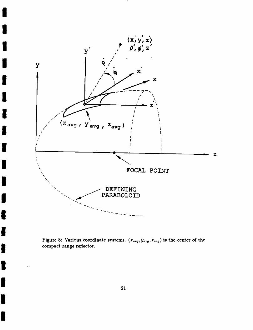
z = z' + zoug 1 Next a cylindrical coordinate system ( p ' q z ' ) with its origin coinciding with
the origin of the (z'y'z') coordinate system can be defined, as shown in
Figure 8. Note that the transformation between the (x'y'z') and the (p'#z')
coordinate system is given by
2' = Q' COS @ y' = p'sintf z' = z'
Let p i ( @ ) be the junction contour of the reflector in (p'@z') coordinate sys-
tem. Then the defining equation of the parabolic part of the main reflector
is
Note that for most of the reflector surfaces pg(4') is a single valued function
of 4'. Then if for a given point on the rim (4' is fixed), the rolled edge is
20
I 1 I I 1 I 1 I 1 1 1 I I 1 I I I 1 I
\ \ I I I
/ I I / I I
I I I I I I I
/ /
/ /
/ /
I
- I - 2
\ DEFINING PARABOLOID
\ \ \
Figure 8: Various coordinate systems. (t,u8,yau8,~,ug) is the center of the compact range reflector.
21

added in p'z' plane, the total surface will be smooth and continuous. Also if
the junction contour is a single valued function of 4', which is normally true,
the rolled edge surface will be unique. Once the rolled edge plane is defined,
one can use the method outlined in Section I1 to add the rolled edge; while,
the method outlined in Section 111 can be used to obtain the rolled edge
parameters. However, to use the method given in Sections I1 and 111, part
of the paraboloid which lies in the p'z' plane (the rolled edge plane) should
be a parabola and one should know the focal length of the parabola and the
junction height. As shown below, the part of the paraboloid in the rolled
edge plane is a parabola, and it is trivial to find junction height and the
focal length of the parabola. Let us assume that the rolled edge is added
at a point corresponding to 4' = 4;. Then the equation of the part of the
paraboloid in the rolled edge plane becomes
Note that Equation (31) represents a parabola of focal length (F). The
vertex of the parabola is at
Thus, the junction height in the rolled edge plane, as shown in Figure 9, is
-. Now one can use the procedure outlined in the last two sections to add
the rolled edge and obtain the rolled edge parameters. Note that since the
22
I I I 1 1 1 I 1 1 I 1 I 1 I I 1 I 1 I

P "
P I' j
I t I
I I 8 1 I 8
' JUNCTION POINT ' P i I Z ' . ) J
INTERSECTION OF ROLLED EDGE PLANE AND PARABOLOID
I
I I
/ I ' I
/ I zj Z / I
f I
I EQUIIVALENT PARABOLA I I I I
FocyoI" I Z t 1 I I/ J
I - I 1
Z
Figure 9: The section of the paraboloid in the rolled edge plane ($2'). Ver- tex of the equivalent parabola coincides with the origin of (p"z") coordinate system.
23

height of the junction, p[i’, may vary with t#~i? the rolled edge parameters
will vary with 4;. From Section 11, the rolled edge in the (p’z’) coordinate
system is defined by
and
where
(37) xp2 = 2F/(pY + 4 F 2 ) 112
Xp3 = p[i’/(p’’ + 4F2)’I2 , and (39)
(40) Yp3 = -2F/(p? + 4 F 2 ) 112
Thus, the whole surface is defined analytically in the (p‘#z’) coordinate
system. For given #, Equation (30) defines the surface for p’ 5 p i ( # ) ; while
24
I I I 1 I I I I 1 I I I 1 I 1 1 I

for p > p i ( # ) , Equations (34) and (35) define the surface as a function of
parametric angle, y.
Next, a blended rolled edge for a concave rim reflector [7,8] (see Ap-
pendix) is designed. The focal length of the reflector is 7.25 feet, and the
reflector is offset in the y direction by 8.5 feet; i.e., zaVg = 0 and yavo = 8.5'.
The scattered fields of the reflector in the target area are also computed.
5 DESIGN EXAMPLE
Figure 10 shows the front view of the junction contour of the reflector. Note
that the junction contour is concave in shape. Equations defining a concave
rim reflector are given in the Appendix. The reflector is symmetric about
the y a x i s and the target zone extends from -4' to 4' in the 2-direction
and from 5.5' to 11.5' in the y-direction. Figure 11 shows the height of the
junction in the rolled edge plane (p'z') versus 4'. Note that the junction
height varies with qS and goes from a large positive value to a large negative
value. However, the variation is quite smooth and reasonable. Thus, one
can optimize the rolled edge parameters for a few points around the rim
and then use interpolation for the rest. Figure 12 shows the total reflector
surface obtained using this process. The rolled edge height is limited to
3.5 feet and the concavity parameters, T, (see Appendix), is also chosen to
be 3.5 feet. The minimum frequency of operation is assumed to be 2 GHz.
A cosine squared blending function [7] is used to blend the elliptical rolled
25

l l t l ui l l t l ' ~ ~ ~ ~ t t
- - - -
JUNCTION CONTOUR
Figure 10: Front view of the junction contour of a concave edge compact range reflector with zlcft = -4', z,ight = 4', ybttom = 5.5', and ytop = 11.5'.
- d-
- -
r _ - t W
G
P
w 6- - _ - -
** - - -
0
- The focal length is 24' and re = 3.5'.
. . . . . . . . . . . . . . . . . . . . . . . . . . . . . . . . . -
- - -
. . . . . . . . . . . . . . . . . . . . . . . . . . . . . . . . . . . . . . . . . . . . . . . . .
3
- - 1 1 1 ~ ~ ~ 1 1 1 l l l l l ~
8. 0. 4. -8. -4.
26
1 1 I I 1 I I 1 1 1 I I 1 I I 1 I I I

Figure 11: Junction height versus 4' for the concave edge reflector.
.. .
27

ROLLED EDGE
JUN CTl ON CONTOUR
S I \ i
Figure 12: Front view of the concave edge reflector with cosine squared blended rolled edges. Rolled edge height = 3.5’, minimum frequency = 2 GHz.
28
1 1 I 1 I I I 1 1 1 1 I 1 I 1 I I 1 I

I 1 I 1 Table 3: Rolled Edge Parameters for the Concave Edge Reflector. F = 7.25 -
feet, minimum frequency = 2 GHz, cosine squared blending.
q5' (deg.) I a, (feet) 90" 118"
139.0856" 160" 180" 200" 216"
220.9 144" 226.0" 234.0" 250.0" 270.0"
0.5 0.5 0.5 0.5 0.5 0.5 0.5 0.5 0.5 0.5 0.5 0.5
b, (feet) 2.7984 2.8128 2.7396 3.2809 3.6719 3.9026 3.9620 3.9574 4.0061 3.9897 3.8700 3.7929
zm (feet) 10.8642 10.8162 10.9962 9.6723 9.0867 8.9810 9.0146 9.0111 9.0927 9.3187 9.8004 10.0663
edge and the paraboloid. The function is defined as
2 1 b(y) = - 4 (1 - cos 2) .
7m (deg-1 105" 105" 105" 105" 105" 105" 105" 105" 105" 105" 105" 105"
It can be shown that the function is a fourth order blending function. Note
that the total reflector surface is smooth and continuous. The whole reflec-
tor fits in a 15' x 13' rectangle and is symmetrical about the y-axis. Table
3 shows the rolled edge parameters for a few points along the junction con-
tour. Recall that for other points the rolled edge parameters were obtained
by interpolation. Since the reflector is symmetric about the y-axis, the
rolled edge parameters are only given for 90" 5 4' 5 270".
29

Figure 13: Scattered fields of the concave edge reflector in the target zone along two vertical cuts. z-displacement = 20‘, Frequency = 2 GHz, Subre- flector feed.
Figure 13 shows the scattered fields for this reflector along two vertical
cuts. The frequency of operation is 2 GHz, and the z-displacement for the
fields cuts is 20‘ from the vertex of the paraboloid. The 2-displacements
for the two vertical cuts is 0’ and 3’’ respectively. The reflector is assumed
to be illuminated by an elliptical subreflector (Gregorian System). The
subreflector ax is and the feed were tilted such that the cross-polarization
for a Huygen’s source feed is zero (111. The subreflector parameters are
..
30

4 s I
- 2- cv I
- s - E-
E I - - n A wrq
E- l
- cq E- l
- z cv ' 0.0
X (FEET)
I I I I 1 I I
GO FIELDS - I - --.- TOTAL FIELDS
.- . . . . . . . . . . . . . . . . . .
.... ....... .-.. *-. .......... -.a .. -.
. . . . . . . . . . . . . . . . . . . . . . . . . . . . . . . . . . . . . - ....*...-- ,---.-.- .--.............. ;...
. . . . . . . . . . . . . . . . . , . : . . . . . . . . . . . . . . . . . . . . . . . . . - ' y = 10.5'
-*.-... -. -.._ .._ ._ - .---. .. . ...*... ... ,.---
. . . . . . . . . .
-
I I I I 1 1
1.0 2.0 3!0 4.0
Figure 14: Scattered fields of the concave edge reflector along three hori- zontal cuts. z-displacement = 20', Ftequency = 2 GHz, Subreflector feed.
ad = 5.25', bd = 4.308', ,8 = 5.5" and (Y = 20" (121. Corrected Po [lo] is
used to compute the scattered fields. For 2 = 3', the fields are displaced
by -0.2 dB so that the two results can be seen in isolation of each other.
For comparison, the GO field level is also shown in the figure. Note that
in most of the target zone, the ripple in the scattered fields is less than 0.1
dB, which is excellent for even the most stringent applications.
Figure 14 shows the scattered fields along three horizontal cuts (y = 6.5',
8.5' and 10.5'). All other parameters are the same as
and 10.5' field cuts, the scattered fields are displaced
-.
31
before. For the 8.5'
by -0.2 dB and -0.4

dB, respectively. Since the reflector system is symmetrical about the y-
axis , the scattered fields only for positive values of z are computed. For
comparison, GO field levels are also plotted in the figure. Again, in most
of the target zone; the ripple in the scattered fields is less than 0.1 dB,
which is very good. Thus, the design procedure leads to blended rolled
edges which cause very small junction diffracted fields in the target zone.
6 SUMMARY AND CONCLUSION
A method to obtain optimum rolled edge parameters for elliptical blended
rolled edges was given. The method ensures that the total height of the
reflector does not exceed the specified value and the minimum radius of
curvature of the reflector meets the requirement at the lowest frequency of
operation. The method also guarantees small diffracted fields.
A procedure to add blended rolled edges to arbitrary rim shaped 3-
dimensional compact range reflectors was also given. The procedure is
applicable to center-fed as well as offset-fed reflectors and leads to rolled
edges with minimal surface discontinuities. Using the procedure, the whole
reflector surface ran be defined analytically using simple expressions. It was
demonstrated that the design procedure leads to reflector surfaces which
have very small diffracted fields emanating from the junction between the
paraboloid and the rolled edge surface.
32
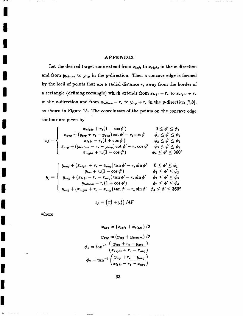
APPENDIX
Let the desired target zone extend from qeft to 2right in the 2-direction
and from ybtt,,,,, to yttop in the y-direction. Then a concave edge is formed
by the locii of points that are a radial distance re away from the border of
a rectangle (defining rectangle) which extends from Zleft - r e to Zright + r e
in the 2-direction and from ybttom - re to ytap + re in the y-direction [7,8],
as shown in Figure 15. The coordinates of the points on the concave edge
contour are given by
right + re( 1 - COS 4') zawg + top + r e - yaug) cot 4' - T e COS 4'
e lef t - r e ( 1 + COS 4') zawg + (Ybottom - r e - youg) cot 4' - r e COS 4'
ztight + re ( 1 - COS 4')
O I V I 4 1 $1 I 4 I 42 4 2 I & 5 4 3
43 I # I 4 4
4 4 5 4' 5 360"
zj =
where
33

- -
34

1 8 I
For a concave rim re should be positive. Note that the parameter re controls
the concavity. The concavity increases with an increase in re. It can be
shown that if re is chosen to be equal to the height of the rolled edge, the zy
projection of the main reflector source (including rolled edge), will extend
from qeft -re to z,ight +re in the x direction and from ybttom -re to ytq + re
in the y direction. If re = 0, one gets a rectangular rim. For re < 0, one
obtains a convex rim (see Figure 15).
I I I I
35

References [l] R.C. Johnson, H.A. Ecker, and R.A. Moore, “Compact Range Tech-
niques and Measurements,” IEEE Trans. Antennas and Propagation, Vol. AP-17, No. 5, pp. 568-576, May 1969.
[2] R.C. Johnson and D.W. Hess, “Performance of a Compact Antenna Range,” Proceeding of IEEE Antenna and Propagation Society, Inter- national Symposium, 1975.
(31 E.B. Joy and R.E. Wilson, “Shaped Edge Serrations for Improved Compact Range Performance,” Proceeding of Antenna Measurement Techniques Association’s 1987 Meeting, Seattle, Washington, Septem- ber 28 - October 2, 1987.
[4] V. Galindo, “Design of Dual-Reflector Antennas with Arbitrary Phase and Amplitude Distributions,” IEEE Trans. Antennas und Propaga- tion, Vol. AP-12, No. 7, pp. 403-408, July 1964.
[5] W.D. Burnside, M.C. Gilreath, B.M. Kent and G.L. Clerici, “Curved Edge Modification of Compact Range Reflectors,” IEEE Transactions on Antennas and Propagation, Vol. AP-35, No. 2, pp. 176-182, Febru- ary 1987.
[6] W.D. Burnside, A.K. Dominek and R. Barger, “Blended Surface Con- cept for a Compact Range Reflector,” Proceeding of the Antenna Mea- surement Techniques Association’s 1985 meeting, Melbourne, Florida, September 1985.
[7] C.W.I. Pistorius, New Main Reflector, Subreflector and Dual Cham- ber Concept for Compact Range Applications, Ph.D. dissertation, The Ohio State University, Dept. of Electrical Engineering, Columbus, Ohio, 1986.
I .. .
1 I I I I I I I I 1 I I I 1 I I 1 I 1
36

[8] C.W.I. Pistorius and W.D. Burnside, “An Improved Main Reflector Design for Compact Range Applications,” IEEE Transactions on An- tennas and Propagation, Vol. AP-35, No. 3, pp. 342-347, March 1987.
(91 I.J. Gupta and W.D. Burnside, “A Physical Optics Correction for Backscattering from Curved Surfaces,” IEEE Trans. Antennas and Propagation, Vol. AP-35, No. 5, pp. 553-561, May 1987.
(lo] I.J. Gupta, C.W.I. Pistorius and W.D. Burnside, “An Efficient Method to Compute Spurious End Point Contributions in PO Solutions,” IEEE Transactions on Antennas and Propagation, Vol. AP-35, No. 12, pp. 1426- 1435, December 1987.
[ll] R.A. Shore, “A Simple Derivation of the Basic Design Equation for Offset Dual Reflector Antennas with Rotational Symmetry and Zero Cross Polarization,” IEEE Transactions on Antennas and Propaga- tion, Vol. AP-33, No. 1, pp. 114-116, January 1985.
[12] C.W.I. Pistorius, G. Clerici and W.D. Burnside, “A Dual chamber Gregorian Subreflector System for Compact Range Applications,” ac-
cepted for publication in IEEE Transactions on Antennas and P r o p - gation.
37