a method to eliminate refraction artifacts in em1002 multibeam
TRANSCRIPT

- NIO/TR-01/2011
AA MMEETTHHOODD TTOO EELLIIMMIINNAATTEE RREEFFRRAACCTTIIOONN AARRTTIIFFAACCTTSS IINN EEMM11000022 MMUULLTTIIBBEEAAMM EECCHHOOSSOOUUNNDDEERR SSYYSSTTEEMM
(Swath Bathymetry & Seabed Surveys of Exclusive Economic Zone)
By
WWIILLLLIIAAMM AA.. FFEERRNNAANNDDEESS
JUNE 2011
NATIONAL INSTITUTE OF OCEANOGRAPHY (Council of Scientific and Industrial Research)
Dona-Paula, Goa. 403 004.

AACCKKNNOOWWLLEEDDGGEEMMEENNTT
I acknowledge Dr. Satish. R. Shetye, Director, NIO for his Kind support. I am obliged to Dr. Bishwajit Chakraborty for his encouragements.
I am grateful to Shri. Andrew Menezes for providing his valuable suggestions and also to my colleagues, who supported me during the developmental stages of this software.
I am thankful to the Ministry of Earth Science (GAP2002), Govt. of INDIA, for financial support in procuring the multi-beam echo-sounder system.
I would also like to acknowledge the officers and crew members of CRV Sagar Sukti (present during operations) for their help & support through-out the multi-beam surveys.
Above all, my beloved family members for their uncountable efforts and constant encouragement in my every prospective for which I shall always be grateful to them.
AABBSSTTRRAACCTT
The multi-beam echo-sounder systems acquire bathymetry data with additional information. This supplementary data along with proper bathymetry can be further used in scientific studies. As observed most of the multi-beam data is occasionally recorded with errors, either geometrical or refraction in nature. But to obtain a map that can be used either for navigation or scientific purposes, it is necessary that the data is error free. As per IHO standards the refraction affected data in shallow waters include uncertainties from navigation point of view. Also, to use in scientific applications it is vital to eliminate these errors from the bathymetry data. The refraction error influences the slant ranged beams and can be easily identified, as the swath shape deviates creating artificial features known as refraction artifacts. In 2007, we conducted an experiment off Goa region and collected multi-beam depth data and sound speed profiles. The reason for this experiment was to analyze the data, identify the errors & develop a software to eliminate the refraction artifacts (in bathymetry data) caused due to the combined effect of wrong sound speed profile and the beam steering offsets(stored in 'calib.txt' file).
CCOONNTTEENNTTSS::
1.0. INTRODUCTION ………………………………………………….
2.0. DISCUSSION………………………………………………………. 3.0. SOFTWARE DEVELOPMENT & DESCRIPTION……………….
3.1. PROGRAM No.1: Extract………………………………………… 3.2. PROGRAM No.2: Corr. ………………………………………….. 3.3. PROGRAM No.3: Re-convert…………………………………….
4.0. SUMMARY....…………………………………………………….. 5.0. REFERENCES……………………………………………………… 6.0. ABBREVIATION…………………………………………………….
1
3 4
4 6
8 10 12 13

LLIISSTT OOFF FFIIGGUURREESS && TTAABBLLEE::
FFIIGG.. 11:: FLOW-DIAGRAM of the Software utilized to remove Refraction Artifacts.
FFIIGG.. 22:: COMPARISON PLOT showing individual raw(a) and processed(b) swaths of the Experimental Multi-beam survey data ( collected in 2007 ) without tide corrections
TTAABBLLEE..11:: STRUCTURE for binary storage & extraction.

A Method Employed to Eliminate Refraction Artifacts in EM1002 Multibeam Echosounder 2011
1
1.0 INTRODUCTION
At National Institute of Oceanography (NIO), Goa the EM1002 multibeam echosounder (MBES) system is used in Hydro-graphic surveys and mapping operations. The system was installed onboard CRV Sagar Sukti in the year 2005[2] and commissioned after its succeeding calibration surveys. Primarily the MBES records the depth values with additional information used for more specific analysis. The acquired data is sometimes recorded along with the noise occurring at the face of the transducer or within the water- column, which induce errors in depths recorded for every beam. The recorded noise is mainly due to following sources such as ship, fish, noise within transducer, bubbles etc. This leads to errors in the acquired hydro-graphic data.
In addition to this, there are other errors emerge from external sensors or instruments connected to either the transceiver unit or acquisition unit. The motion sensor along with the DGPS malfunctioning also affects the data. Apart from this the sound velocity value at transducer surface and within the water column plays an important role in ray-bending and ray- tracing. If any one of them deviates, the full calculations (performed by the multibeam system) for depth information becomes invalid. These error makes the MBES data un-usable for hydro-graphic as well as for any scientific applications. The errors occur in the bathymetry data due to wrong sound speed at transducer or within the measured sound velocity profile are called as refraction errors (smiles or frowns). These errors inturn generates artificial (un-natural) features known as refraction artifacts. These errors are known to be more dominant in tropical region, where sound speed varies frequently.
Another reason for refraction error is the wrong beam steering offsets(present in a ‘calib.txt’ file), which are used at the time of acquisition. The EM1002 MBES system utilizes these offsets to steer the beams in the required direction. The file was created (by OEM) during the calibration survey and is utilized during beam-steering process so that the beam angle is adjusted for proper reception. But if these beam steering offsets were generated using refraction affected survey lines then the whole survey will be at fault.
During the experiment(in 2007), the multi-beam echo-sounder data along with SSPs were collected. Additionally CTDs (4 Nos) were also deployed at the same locations for sound velocity measurements. The sound velocity profiles(using CTD data) are calculated using the following equations:
Wilson
Del Grosso
Chen and Millero
Even after using the SV profiles (derived from CTD data using above equations), no improvement in the multibeam data was observed. On further analysis the multibeam

A Method Employed to Eliminate Refraction Artifacts in EM1002 Multibeam Echosounder 2011
2
data was found to have errors, due to the combined effect of sound speed profile and 'calib.txt' file. As observed, the sound velocity measurements were very close but not stable every time. The deviations were found to be 0.5m/s to 0.9m/s. And this accuracy lag was observed to be unacceptable for multibeam surveys. During this time beam steering offset file was not nullified. Hence in offline post processing the "calib.txt" file was applied (by multiplying -1 to all the beam values included in the file), so as to nullify its effect on the data acquired, after which these profiles were tried one at a time to observe any improvements in the data, but with no success.
In the same year another experimental bathymetry survey, the SVplusV2 (from M/s Applied Microsystems)was employed which have shown some improvements in the data. But the refraction errors were still noticed in the outer-beams, hence the map shows false features at the merging of adjacent survey lines. This confirmed that the errors are due to invalid beam steering offsets (calib.txt file) and are of refraction in nature. This wrong offsets in the file are due to the utilization of wrong sound speed profile.
Due to the above situation, it was decided to correct the data by manufacturing the SV profile using the OEM post processing software suite. This task was time consuming and processing was very slow. Finally the seafloor surface chart was obtained with little deviations in data quality. This allowed us to think in the direction to correct for these errors in the acquired data. During the analysis of the data, it confirmed to have more errors of different types and nature. The errors observed are given below:
Improper Motion and position delays.
Erroneous sound velocity profile.
Incorrect time stamping.
Due to time delay in motion sensor the swaths will be corrected using the earlier motion data hence roll, pitch, heading and heave stabilization will be inappropriate for all the beams in a ping. Position data carries different messages such as given below:
GGA- Fix information GLL - Lat/Lon data VTG - Vector track and Speed over the Ground ZDA - Date and Time
With position delays, positioning and time stamping (as received by DGPS) for the data used will be incorrect. Inaccurate time stamping also occurs when the change over takes place or operator performs change over from DGPS to system time when PPS fails.
The report focuses on the software developed at NIO, that is capable of reducing (or removing completely) the refraction artifacts efficiently. The software is discussed in more details in the subsequent sections.

A Method Employed to Eliminate Refraction Artifacts in EM1002 Multibeam Echosounder 2011
3
2.0 DISCUSSION
Initially at start-up, the EM1002 multibeam echosounder system automatically checks for all the components in the Transceiver unit, for instance: transmitter receiver channels, beam-forming and signal processing (BSP), processing unit status etc. The SIS data acquisition software also performs the above task (on operator’s command), once built- in- self test (BIST) is initiated.
During data collection, the system uses the phase interpolation & amplitude techniques to compute the depth for a particular beam. Generally within central fan the amplitude method and outside up to ±75° the phase interpolation methods are applied. The system also shows the noise level for each beam either occurring at the face of the transducer or within the water column.
The error in computing depth (for each beam) involves parameters, for example sound velocity recorded at transducer face and the sound speed profile (for ray bending and ray tracing), application of beam steering offsets ( as the case with EM1002 system), motion (roll, pitch, heading, heave) data etc. Any deviation in the above parameters will introduce errors. The report is limited to the errors caused either by sound speed at transducer (Tx) surface or by sound velocity profile(SVP). The errors originated by incorrect sound speeds, appear as smiles or frowns and are named as refraction errors. These are very effective and difficult to eradicate from bathymetry data. Moreover they also influence the supplementary data, which the system records along with the bathymetry. This leads to un-natural features (called artifacts) in the bathymetry data thus misguiding the interpreter. This can be easily identified in the data and mostly observed in the outer-beams of the survey line.
Likewise at the time of system calibration inputting an incorrect sound velocity profile will generate inaccurate beam steering offsets (stored in Calib.txt file). These offsets are purely generated by OEM engineer. At the time of data acquisition the system utilizes these offsets (Calib.txt file) to force the beams in particular direction for data reception, thus adding errors in the acquired survey data.
Though the Neptune post-processing software of the EM1002 MBES system[5] has the flexibility to correct for these errors, it is devastating as the process is manual that means the operator have to create (or adjust the original) sound speed profile[3] and then apply in post-processing software and this process will go on until the swaths are free from refraction errors. This task is demoralizing and the operator has to monitor for improvements continuously.
Therefore it was thought of building a software, which will handle these errors effectively, thereby outputting artifact free multibeam data.

A Method Employed to Eliminate Refraction Artifacts in EM1002 Multibeam Echosounder 2011
4
3.0 SOFTWARE DEVELOPMENT AND DESCRIPTION Soon after the commissioning of the EM1002 MBES system onboard CRV Sagar Sukti, the hydro-graphic surveys were conducted. While acquisition of the multibeam data the errors were observed (as discussed above) and the effort was made to eliminate these errors from the data. Before developing the software, the Experimental raw data was actually processed and analyzed for different error effects as explained above. Upon post-processing and careful analysis, the data was perceived to be dominated by errors of refraction[3]. As discussed earlier the attempt was made to correct for these refraction errors using OEM software suite, to some extent it was useful. But this process involved continuous monitoring of data quality. The process was tedious and also time consuming. Thus decided to develop a program/software which will correct the data for the errors caused from incorrect sound velocity input. Here we have used different but simple approach, to correct the swaths and eliminate artifacts, preventing the real features from any effects. The aim of the software is to remove refraction artifacts present in the data, quickly and efficiently with less processing time, but without affecting the actual features. The software is made as a self extraction package, that extends its services from extraction of the required parameters (present in data-grams) to reconversion (to binary *.all files). The following are the core programs, explained in brief sequentially.
3.1 PROGRAM NO. 1: Extract
Initially, the program executes the built-in Batch-file Generation Unit (BFGU) and creates a batch file consisting of filenames of raw data (*.all). Secondly it places the filename of raw data in to the program buffer & automatically extracts the required parameters. These parameters are stored in a Binary formatted file using a binary structure as mentioned in the below given Table 1. This program does skip the frames which are not required for the depth processing. In case of less frame size of necessary datagram it reads up to the final byte as required, but considering only full beam depth information. The program extracts information from the following data-grams as listed:-
Depth data-gram. Seabed Image data-gram. Raw range & beam angle. Position data-gram.
During file reading operation, it becomes necessary to check for the information such as type of data-gram and number of bytes (for simple reason of datagram extraction and frame skipping), accordingly the specific data records are extracted. This information is written in a defined packet type format (binary) to an output file.

A Method Employed to Eliminate Refraction Artifacts in EM1002 Multibeam Echosounder 2011
5
The program also extracts the calib.txt file The process continues for rest of the raw files, whose filenames are stored in the batch file. This is a basic program that extract the parameters, from the raw data-grams recorded in raw files. These parameters are listed in the Table.1 given below:
Input structure
(All are integers)
Output structure
(All are integers) Description
BNo BEAM Beam Numbers
NoB TOTAL Number of Beams
TITA THETA Incidence Angle
LONG LONT Longitude
LATD LATT Latitude
DINC DEPTH Raw Depth
RANG RANGE Raw Range
DPRS DPRSS Depression Angle
GYRO HEAD Vessel Heading
WIND DWIN Window Detection Length
CROA TVG Cross Over Angle
BCTR CTR Center Beam
TABLE.1: STRUCTURE for binary storage & extraction.
Additionally the program generates the XYZ formatted files for plotting in the third party softwares such as ArcGIS[6] etc. And also provides the output to check the depths of the swaths individually or combination of pings (using wgnuplot software), either referencing to beam numbers or beam incidence angles .

A Method Employed to Eliminate Refraction Artifacts in EM1002 Multibeam Echosounder 2011
6
3.2 PROGRAM NO. 2: Corr
This program receives the raw extracted depths from program-1 (extract). The program have an in-built file-splitter, essential in the case of huge processing area. The purpose of the program (Corr) is to output the refraction free depths. This is achieved in 4 steps summarized as follows.
3.2.1 First step: Swath shape identification:
The in-built file splitter determines the shape of each swath (to define CASE type) from the survey line, for which the following points were considered.
The center-beam (depth value) is assumed to be correct.
Within the crossover angles (±25°), it is assumed to have correct depth values compared to outer beams, due to narrower incidence angles and are in close proximity with center beam.
The CASE type indicates the shape of the refraction affected swaths. This enables the program to understand (for smiles or frowns) and utilize the averaging method.
3.2.2 Second step: Averaging N swaths:
Here, the array (of size of total beams recorded) is used to store the beam depths of N swaths.
Eq:2
The beam depths are stored according to the beam number(i) in their respective array (arr[i]) such as given in Eq.2. This array is averaged for every bunch of swaths within the survey area identified and is then used for computing the beam offsets.
alt_diff[i]= (alt[c]- alt[i]) + alt_diff[i] 1 ≤ i ≤ 111 i < c, > c i > c , < c
arr[i]= depth[i] + arr[i] , f[i]= f[i] + 1
av[i]= (arr[i] / f[i]) + av[i]
Eq.1.
Eq.3. 1 ≤ i ≤ 111
1 ≤ i ≤ 111

A Method Employed to Eliminate Refraction Artifacts in EM1002 Multibeam Echosounder 2011
7
3.2.3 Third step: Offset Computation:
After obtaining the swaths average, the differences between average of beams with center beams average is calculated and accordingly by utilizing the number of times storage(s).
At this point the optimization of coefficients (offsets) are now be carried out. The offsets are crucial to nullify the refraction artifacts in the depth data.
3.2.4 Four step: Application of the offsets on raw depth swaths:
The application of these offsets on every swath of the survey line improves the data quality[FIG.2]. This correction process works in the background while replaying the raw formatted binary data file. The corrected data is then stored in the same binary format (using structure at Table.1).
However the program also outputs ASCII xyz data used for plotting in ArcGIS software[6] etc. The program is also equipped with online plots generating facility to display raw and processed depth data. In the end, the program also generates the new batch file (used further in third program: Re-convert).
diff[i]= [diff[i] + (av[i] - av[c])]
offset[i]= diff[i] /s Eq.4.
depth[i]= depth[i] - offset[i] Eq.5.
1 ≤ i ≤ 111
-1<c<1, i=c
1 ≤ i ≤ 111

A Method Employed to Eliminate Refraction Artifacts in EM1002 Multibeam Echosounder 2011
8
3.3 PROGRAM NO. 3: Re-convert
This program employs the defined structure to store the corrected depth data in the data-grams with the recorded supplementary data back in binary simrad (*.all) format. The program enables the splitter section for splitting the corrected file (the output of Corr- program) into 1GB sections. And creates the batch file in which the filenames of the splitted data are stored.
In re-conversion only corrected depths are placed back in the file on their same place, without affecting any of the information or data-grams within the file. All these modifications are confirmed by employing "CHECKSUM"(used to check the sum of data between STX and ETX), as the case in the raw acquired data-grams.
The reason to convert the data back to the same binary format is that, the data acquired had only dominating refraction errors. The cause for these errors was already discussed above, but other remaining errors (if present) can be easily exterminated using Neptune post-processing suite, as it provides graphical interface, filtering methods for elimination of positional spikes, other calibration (roll, pitch heave and heading) related errors and tide compensation.
Finally the processed depth data is re-written into the files having same file number, date, time but different suffix as demonstrated below:
0000_20060109_054705_SagarSukti.all
0000_20060109_054705_SagarMB.all
NOTE:
Line no.:0000
Date: 20060109
Time: 054705
Vessel Name: SagarSukti
File Format Extension: .all
The software allows the operator to change the suffix (SagarMB), but forbids to change the number, date and time field. After ending the read & write process the software comes to halt. This program only generates the binary file with the file format extension as defined above. The extension is necessary, so that the file import process will recognize the file as binary simrad format file.

A Method Employed to Eliminate Refraction Artifacts in EM1002 Multibeam Echosounder 2011
9
FIG.1: FLOW-DIAGRAM of the Software utilized to remove Refraction Artifacts
BFGU: generates the batch file containing the raw filenames for recall during processing.
Extract: Parameters extraction. Raw Depth & Raw Range. Beam Positions & Vessel
Heading Beam incidence & Cross-over
Angles. etc.
Corr:
Locates CASE types (type of refraction effects; smiles/frowns).
Switching on averaging method depending on CASE types
Reconvert: Data reconversion to binary simrad (*.all) for eliminating motion errors and for tide compensation.

A Method Employed to Eliminate Refraction Artifacts in EM1002 Multibeam Echosounder 2011
10
4.0 SUMMARY
The Multibeam echosounder systems are bound to have errors of different kinds. Mostly due to un-favourable weather conditions while surveying. However errors are also caused due to operator negligence. The operator is in-charge of the quality- data collection and even after taking precautions, the errors are so dominant that, they mislead the user leading to improper data acquisition.
Here, one of the error focussed upon, is the refraction error which causes the smiling or frowning effect in the swaths. As discussed above the refraction occurs due to incorrect sound speed at Tx or sound speed profile measured within the water column (extended from sea surface to seafloor maximum upto 12000m). However in EM1002 MBES system, the file called 'calib.txt' (containing beam steering offsets) is also responsible for refraction errors, as it is used while data acquisition[4].
The software first extracts the depth data with additional parameters (see Table:1) from the data-grams available in the raw data acquired and stores in specific defined structure for binary storage[Table:1]. In the second program the swath shapes are inspected for the refraction artifacts and accordingly assigns the CASE number depending on smiles or frowns like features. Later the data is allowed to pass through the splitter (bypassed for smaller size files <1GB) to split the bigger size files into 1GB smaller sections and the names are supplied sequentially, then these names are stored in a batch file. On advancement of the program, the data from the splitted files is processed and the offsets are made available to correct the multifaceted errors mentioned above. On ending the correction program, the software generates the corrected xyz format files, as can be used in the third party softwares such as ARCGIS (for creating plots), Matlab (for more specific analysis) etc.
Using third program, the processed data is stored back to the binary SIMRAD (*.all) format. The further task of post- processing for removal of the residual errors/offsets is achieved using the Neptune post-processing software suite[5] (M/s Kongsberg Maritime). The Neptune processing software generates 2D maps or grids, while third party softwares are utilized to create 3D maps and for more specific applications such as volume analysis, the cross sectional analysis across different locations within the data set etc.
Hence using the above method, the multibeam bathymetry data can be restored from refraction artifacts caused due to the deviations in sound speed profiles, sound speed logged at Transducer and the effects of calib.txt (containing beam steering offsets) file generated during calibration of the EM1002 multibeam echosounder system.

A Method Employed to Eliminate Refraction Artifacts in EM1002 Multibeam Echosounder 2011
11
(a)
(b)
FIG.2: COMPARISON PLOT showing individual raw(a) and processed(b) swaths of the Experimental Multibeam survey data ( collected in 2007 ) without tide
corrections.

A Method Employed to Eliminate Refraction Artifacts in EM1002 Multibeam Echosounder 2011
12
5.0 REFERENCES
[1] Edouard Kammerer and John E. Hughes Clarke,(2000) New Method for the Removal of Refraction Artifacts in Multibeam Echosounders Systems. Canadian Hydrographic Conference Montréal 16-18 May 2000.
[2] Fernandes, W and Chakraborty, B (2009) Multibeam backscatter image data processing techniques employed to EM 1002 system. Proc. of the International Symposium on Ocean Electronics (SYMPOL-2009), 18-20 November 2009.
[3] Fernandes, W.A., (2007) An Approach Towards Solving Refraction Problems in EM1002 Multibeam Echosounder system. NIO-Technical Report(NIO/TR-03/2007).
[4] Fernandes, W.A., (2009) A Report on EM1002 Multibeam Echosounder System Maintenance. NIO-Technical Report(NIO/TR-02/2009).
[5] Anon, 2006. Using Neptune post-processing software suite (version 6.6 ), M/s Kongsberg Maritime, Norway.
[6] Anon, 1998. Using ArcMap (ESRI version 8.3), ESRI Inc., USA.
A Method Employed to Eliminate Refraction Artifacts in EM1002 Multibeam Echosounder 2011
13
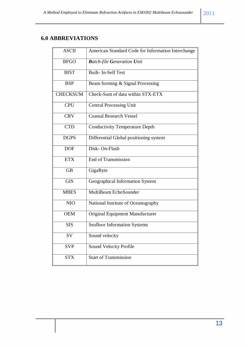
6.0 ABBREVIATIONS
ASCII American Standard Code for Information Interchange
BFGO Batch-file Generation Unit
BIST Built- In-Self Test
BSP Beam forming & Signal Processing
CHECKSUM Check-Sum of data within STX-ETX
CPU Central Processing Unit
CRV Coastal Research Vessel
CTD Conductivity Temperature Depth
DGPS Differential Global positioning system
DOF Disk- On-Flash
ETX End of Transmission
GB GigaByte
GIS Geographical Information System
MBES MultiBeam EchoSounder
NIO National Institute of Oceanography
OEM Original Equipment Manufacturer
SIS Seafloor Information Systems
SV Sound velocity
SVP Sound Velocity Profile
STX Start of Transmission