a methodology and tool for top-down relational database...
TRANSCRIPT

Data & Knowledge Engineering 10 (1993) 259-291 North-Holland
DATAK 165
( '{ .;, I
259
A methodology and tool for top-down relational database design
Naphtali Rishe School of Computer Science, Florida International University , University Park , Miami, FL 33199, USA
Abstract
Rishe , N., A methodology and tool for top-down relational database design, Data & Knowledge Engineering 10 (1993) 259-291.
This paper presents a methodology for logical design of relational schemas and integrity constraints using semantic binary schemas. This is a top-down methodology. In this methodology, a conceptual description of an enterprise is designed using a semantic binary model. Then. this description is converted into the relational database design. The paper also describes a tool which automates all the busy work of the methodology and provides graphic output. With respect to the intelligent design decisions. the tool accepts instructions from its user , who is a database designer , or, when the user defaults, makes decisions itself based on ·rule-of-thumb' principles.
Keywords. Database design, relational databases: semantic databases: CASE tools: methodology: database schemas; integrity constraints.
I. Introduction
In the methodology presented in this paper, semantic binary schemas are converted into relational schemas and integrity constraints. The semantic database models offer a simple, natural, implementation-independent, flexible, and non-redundant specification of information and its semantic aspects. Since the original idea of [1], many semantic data models have been studied in the Computer Science literature. Many semantic models have been surveyed in [2] and [3]. Although somewhat differing in their terminology and their selection of tools used to describe the semantics of the real world, the various semantic models are roughly equivalent. This paper's methodology uses the Semantic Binary Model (SBM) [4-8], a descendant of the model of [ 1]. Models similar to SBM have been studied in [9-18], and others. SBM does not have as rich an arsenal of tools for semantic description as can be found in some other semantic models, e.g. the IFO model [19], SDM [20], the Functional Model [21-23], SEMBASE (24], NIAM [11, 25, 26], Taxis [27], SIM [28], SAM [29], OSAM* [30], GEM [31], GENESIS [32], ER [33], Extended ER [34]. Nevertheless, the SBM has a small set of sufficient simple tools by which all of the semantic descriptors of the other models can be cbnstr.ucted.
Non-procedural languages for semantic databases have been studied in [35 , 22, 13, 36, 37],
Correspondence to: N. Rishe. School of Computer Science. Florida International University, University Park . Miami, FL 33199. USA , fax: 305-348-3549, email: [email protected]
This research has been supported in part by grants from the Florida High Technology and Industry Council and the US Department of the Interior.
0169-023X / 93 /$06.00 © 1993- Elsevier Science Publishers B.Y. All rights reserved
9?.6

260 N. Rishe
and others. Extended Pascal data manipulation language for semantic databases is defined in [38] and [6]. Data definition languages integrated with data manipulation languages for semantic databases have been studied in [39].
The use of semantic models for the design of relational schemas has been studied in [40, 33, 41, 42, 26, 43, 44, 25, 45, 46], and other works. A graphical interactive system for the design of semantic databases is discussed in [47].
The methodology proposed herein differs in the satisfaction of a broad range of schemaquality criteria (to be introduced); in comparative analysis of different design choices in various steps of design; and in systematic generation of integrity constraints. Among the novel points in the methodology are procedures for the generation of keys of categories and for partitioning of non-disjoint categories into disjoint ones. The treatment of sub-super categories and non-disjoint categories is important for the proper reflection of the original semantics in the resultant relational schema and for avoidance of logical redundancy of information in the database. Other methodologies (e.g. [44, 25, 46]) do not address this issue explicitly. On the other hand, they do address other issues that the methodology of the present paper does not consider directly. In the input semantic model of this methodology, SBM, the semantic issues that are rather simple to the user are graphically explicit. Other semantic nuances are relegated to integrity constraints, and they are propagated into the relational schema's external integrity constraints. For example, the input model of [44] allows nested relationships.
This paper begins with a brief description of the semantic binary model. Objectives of schema design follow. Then the methodology is presented. Then an automatic tool is described. The last section compares this methodology to the normalization methodology.
2. The semantic binary model
This section describes the semantic binary model. The semantic binary database model represents information of an application's world as a
collection of elementary facts of two types: unary facts categorizing objects of the real world and binary facts establishing relationships of various kinds between pairs of objects.
One of the major advantages of the relational database model, as compared to the network and hierarchical models, was the independence of the logical data from the physical aspects of data storage. The semantic models went one step forward towards the independence of the actual information from its logical data representation. Among the semantic advantages of the semantic binary model relative to the relational model are the following: -All the information is composed of the elementary facts describing the real world, so no
normalization of a semantic binary schema is needed; -No category (type) of objects needs to have a key. A key is collection of attributes which
are never null and which universally identify the objects of the category. (Instead of having a fixed inflexible key, in the semantic model different objects of the category may be identifiable by different attributes or by different relationships with objects of perhaps other categories. In the real world, keys exist very rarely. Another practical requirement of the keys in most systems is that their values do not change in time. (Even if the system does not guard keys against change, arbitrary changes may cause inconsistency of the database.) On the other hand, all natural attributes should be allowed change in time: if not because of the changes in the real world then because of correction of erroneously recorded data.)
- Objects are not logically replaced by their keys, when these exist. So a value of a key is changeable with no influence on the other information about this object in the database.

Top-down relational DB design 261
-An object may belong to several categories simultaneously. -Properties which are common to several categories, can be specified just once. - It is conceptually simple and schemas can be easily explained to owners of the information
to be stored in the database, who may have no computer knowledge but must approve the conceptual schema.
A definition of the model's concepts follows.
2.1. Categories
Object- Any item in the real world. It can be either a concrete object or an abstract object as follows.
Value, or Concrete object- A printable object, such as a number, a character string, or a date. A value can be roughly considered as representing itself in the computer, or in any formal system.
Abstract object- A non-value object in the real world. An abstract object can be, for example, a tangible item (such as a person, a table, a country), or an event (such as an offering of a course by an instructor), or an idea (such as a course). Abstract objects cannot be represented directly in the computer. This term is also used for a user-transparent representation of such an object in the Semantic Binary Model.
Category (also called Entity Type or Entity Set in some semantic models)- Any concept of the application's real world which is used for classification of objects. At every moment in time such a concept is descriptive of a set of objects. Unlike the mathematical notion of a set , the category itself does not depend on its objects: the objects are added and removed while the meaning of the category is preserved in time. Conversely, a set does depend on its members: the meaning of a set changes with the ebb and flow of its members. Categories are usually named by singular nouns. An object may belong to several categories at the same time.
Disjoint categories -Two categories are disjoint if no object may simultaneously be a member of both categories. This means that at every point in time the sets of objects corresponding to two disjoint categories have empty intersection.
Subcategory- A category is a subcategory of another category if at every point in time every object of the former category should also belong to the latter. This means that at every point in time the set of objects corresponding to a category contains the set of objects corresponding to any subcategory of the category.
Abstract category -A category whose objects are always abstract. Concrete category, category of values- A category whose objects are always concrete. Many
concrete categories, such as NUMBER, STRING, and BOOLEAN, have constant-in-time sets of objects. Thus, those concrete categories are actually indistinguishable from the corresponding sets of all numbers, all strings, and the Boolean values ({TRUE, FALSE}).
2.2. Binary relationships
Binary relationship- Any concept of the application's real world which is a binary property of objects, that is, the meaning of a relationship or connection between two objects. At every moment in time, the relationship is descriptive of a set of pairs of objects which are related at that time. The meaning of the relationship remains unaltered in time, while the sets of pairs of objects corresponding to the relationship may differ from time to time, when some pairs of objects cease or begin to be connected by the relationship .

262 N. Rishe
Notation: 'xRy' means that object xis related by the relationship R to object y. Types of binary relationships • A binary relationship R is many-to-one (m: 1, functional) if at no point in time xRy and
xRz where y ¥- z. • A binary relationship R is one-to-many (I : m) if at no point in time xRy and zRy where
X¥- Z. • Relationships which are of neither of the above types are called proper many-to-many
(m:m). • A binary relationship which is both m: 1 and I : m (always) is called one-to-one (1 : 1 ). • A binary relationship is proper m: 1 if it is m: 1 and not I : 1. • A binary relationship is proper 1 : m if it is 1 : m and not I : I . Domain and range of a binary relationship: A category C is the domain of R if it satisfies the following two conditions: (a) whenever xRy then x belongs to C (at every point in time for every pair of objects); and (b) no proper subcategory of C satisfies (a). A category C is the range of R if: (a) whenever xRy then y belongs to C (at every point in time for every pair of objects); and (b) no proper subcategory of C satisfies (a). Total binary relationship- A relationship R whose domain is C is total if at all times for every
object x in C there exists an object y such that x Ry. (At different times different objects y may be related to a given object x.)
Note No relationship needs to be total on its domain .
2.3. Non-binary relationships
Non-binary relationships - Real-world relationships that bind more than two objects in different roles. Such complex relationships are regarded in the binary model as groups of several simple relationships.
In general , the binary model represents any non-binary relationship as: (a) An abstract category of events. Each event symbolizes the existence of a relationship
between a group of objects. (b) Functional binary relationships, whose domain is the category (a). Each of those
functional binary relationships corresponds to a role played by some objects in the non-binary relationship .
Thus , the fact that objects x 1 , ••• , X11
participate in an n-ary relationship R in roles R 1 , ••• , R
11, is represented by:
(a) an object e in the category R ', and (b) binary relationships eR 1x 1 , ••• , eR
11X
11•
2 .4. Graphic representation of schemas
( 1) In a schema, abstract categories are shown by rectangles. (2) Relationships from abstract categories to concrete categories are shown inside the boxes
of the domain-categories as follows:
relationship: range type
The range is specified as a programming language data-type. (We will use the style of Pascal here.) Usually, relationships between abstract and concrete categories are m : 1. This is the

Top-do~111 relational DB design 263
default type of relationships whose ranges are concrete categories, and it need not be explicitly specified in the schema for such relationships.
(3) Relationships between abstract categories are shown by arrows between the categories' rectangles. (The direction of the arrow is from the domain to the range.) The name and type of the relationship are indicated on the arrow. The default for the type of relationships between abstract categories is m: m.
( 4) Subcategories are connected to their supercategories by arrows with dashes. (5) The disjointness of categories is indicated implicitly:
(a) Two categories which have a subcategory in common are not disjoint. (The common subcategory does not have to be their immediate subcategory, that is, it may be a subcategory of a subcategory, and so on .)
(b) Two categories which are subcategories of one category (not necessarily immediate subcategories) are considered not disjoint , unless otherwise declared in an appendix to the schema.
(c) The other categories are disjoint from each other , unless otherwise declared in an appendix to the schema.
Figure 1 is an example of a semantic binary schema.
, , ,"" ....--------(
STUDENT
COURSE ENROLLMENT ~t-he_o_~_e_r~
finaf.gradf.' 0 .100 (m :f)
PERSON
laSHIOmt' ·String firsl·t1Ut1U' .' Stnng
birth-year: 1870 .. 1990 addrtss: String
DEPARTMENT
namr · Strm~ I ·m
COURSE OFFERING
~ ... ,,, )-------,
INSTRUCTOR
the course COURSE
(m : l ) namt: String 1:1
the quarter (m ·l)
QUARTER
yrar · / 980 .. /995 ua.son : String
Fig . I . A semantic sche ma for a university app lica tio n. Boxes are abstract ca tegories with their attributes (concrete re lations) . STUDENT and INSTRUCTOR are nondisjoint subcategories of PERSON. The relation works-in is
many-to-many.

264 N. Rishe
3. The relational model
For convenience of the database design and use of languages, this section defines the Relational Model as a subset of the Semantic Binary Model. Attribute- A functional relationship whose range is a concrete category.
The phrase 'a is an attribute of C' means: a is an attribute, and its domain is the category C.
Time-invariant attribute- An attribute A is time-invariant if once an object x becomes related by A to a value y, the object x will forever be related by A toy, as long as x exists. There are no time-invariant attributes in the natural user world. Even if the laws of physics or society do not allow for an attribute to change in time , the attribute may change in the perceived real world due to discoveries of errors in earlier perception. For example, a social security number could be wrongly reported and then corrected. Thus, timeinvariance is defined only in implementational restrictions. Such restrictions are unavoidable in the relational database design. The methodology of relational schema design that is presented below has among its goals the minimization of the negative effect of such implementational restrictions.
Keys ( 1) Single-attribute key
A time invariant attribute of a category is called its key if it is 1 : 1 and total. That means that the values of the attribute can be used to identify the objects of the category. Due to the time-invariance requirement, no attribute is really a key in the natural user's world. Thus, the property of a key is defined only in implementational restrictions, which are unavoidable in the relational database design. Also , the requirement of totality is very rarely an integrity constraint imposed by the logic of the user world , but rather is an implementational restriction.
Convention In this paper, we shall name the attributes constrained to be keys with the suffix key .
(2) Multi-attribute key The following definition extends the concept key to a collection of attributes.
Key of a category- A collection of total time-invariant attributes f 1, f2 , ••• , /,, whose domain is that category s. t. (i) For any collection of values, x 1, ••• , x, there is no more than one object y of the
category s. t.
x 1 = y . f 1 and x2 = y . / 2 and ... and x, = y . /,, .
(ii) No proper subcollection of these attributes always satisfies (i). Practically , requirement (i) means that the collection of attributes is sufficient to identify every object of the category. Requirement (ii) means that the collection is minimal: if one of the attributes is not known then the remaining attributes might not provide sufficient information to identify every object of the category.
Convention In this paper, when a category is constrained to have exactly one key, and the key is composed of several attributes, we shall name these attributes with the suffix -in-key.
Note (i) In the real world a category usually has no key. Thus, the existence of a key is usually
not an integrity constraint but rather an implementational restriction. This restriction

Top-down relational DB design 265
will be imposed when unavoidable due to limitations of a DBMS or a database model, especially the Relational Model.
(ii) Existence of a key makes every object of the category identifiable with the values of the key and eliminates the necessity to refer to abstract objects.
(iii) A category which has no key may still have all its objects completely identifiable (using different relationships and their combinations for different objects), but the identification would not be uniform.
(iv) When a key is composed of several attributes it is still one key . (v) A category may theoretically have several keys . However, since categories in the real
world rarely have even one key, the existence of more than one key· would be an unnecessarily strong implementational restriction (particularly because the timeinvariance requirement) , which is not required by database management systems. The possibility of more than one key (called candidate keys in some literature) is irrelevant to the purposes of this paper. In the design algorithm we start with no keys (which is a natural state) and create one key per category (which suffices for the relational schema) .
A binary schema is called table-oriented, or a relational schema if (i) all the abstract categories of the schema have keys,
(ii) all the abstract categories are pairwise disjoint , (iii) the only relationships are attributes. Thus , all the information in a relational schema is represented by attributes of categories.
Example Figure 3 shows a relational schema with three tables which corresponds to the semantic schema of Fig. 2.
INSTRUCfOR
last-no~: String first-no~ : Siring
birth-ytar: 1870 .. 1990 addrtss: String
works in DEPARTMENT
(m:m) main-no~: Siring 1:/
Fig. 2. A semantic schema.
WORK
inslructor-id-in-kty: lnttgtr dtparl~nHnoin-na~-in-lcty: String
INSTRUCfOR
DEPARTMENT id·kty: /nl(gtr I :I lasl-no~: String firsl-na~M : Siring main-na~-kty: String 1:1
birth·ytar: 1870 . .1990 addrtss: String
Fig. 3. A relational schema.

266 N. Rishe
4. Design goals
4.1. Quality of schemas
A schema is said to be of high quality if it satisfies the following criteria (cf. Chapter 2 of [34].) (1) The schema describes the concepts of its application's world naturally:
• The schema describes the objects, categories and relationships as they are in the real world.
• The users can translate ideas easily in both directions between the concepts of the schema and the natural concepts of the application world.
(2) The schema contains very little or no redundancy. The redundancy should be avoided not in order to improve the storage efficiency -the storage is not that expensive nowadays. The redundancy should be avoided primarily in order to prevent inconsistency of the database and its update anomalies. When the redundancy is needed for the convenience of the users , it should be introduced into the user-views but not into the schema. In some database models we cannot eliminate the redundancy completely. When we have to have some redundancy, we should at least bind it by integrity constraints. When such constraints arc implemented , the user is forced to update all the related facts simultaneously.
(3) The schema docs not impose implementational restrictions, i.e. every situation probable in the real world of the application is fully representable under the schema.
( 4) The schema covers by itself as many integrity constraints as possible, that is, the class of instantaneous databases formally possible according to the schema is not much larger than the class of all possible situations of the real world. Constraints that arc not expressed in the schema cause these problems: • They are hard to formulate and to specify. • They are seldom enforced by the DBMS. Thus, they require a substantial application
programming effort for their enforcement, arc often implemented incorrectly, and usually prevent direct interaction between the user updating the database and the DBMS (the user may not use the standard language for simple updates , which is supplied by most DBMS) .
• The users and application programmers often forget or misunderstand such constraints.
(5) The schema is flexible: if probable changes in the concepts of the application world occur, the schema would not have to undergo drastic changes.
(6) The schema is conceptually-minimal: it docs not involve concepts which are irrelevant in the application's real world, and limits the accumulation of information which is irrelevant in that world.
The most important issue of the database design is the design of a high-quality schema within the restrictions of the available DBMS and database model. A low-quality schema increases the chances of corruption of the data , makes it very hard to use and maintain the database, and makes it very hard, if not impossible, to adjust the database to the changing concepts of the application 's real world .
It is easy to design a high quality schema in semantic models, particularly the Semantic Binary Model. The task is much harder in the Relational Model. Moreover. it is usually impossible to describe an application world by a schema in the Relational Model with the

Top-down relational DB design 267
same high quality as with which that application can be described in the Semantic Binary Model.
The objective of this paper is to make the task of design of a relational schema easy once a semantic binary schema has been designed.
4.2. Objectives of schema conversion
A schema-conversion is a replacement of a schema by another schema having the same information content. This means that each of the two schemas can be regarded as a user-view of the other.
Schema-conversion is a means of database design: a schema is first designed in a higher-level database model and then translated into a lower-level model which is supported by the available DBMS (when a DBMS for a higher-level model is unavailable or inadequate). This paper presents a conversion algorithm of an adequate semantic schema into a relational schema whose quality is among the highest possible for the Relational Model.
The quality of the resulting schema is assessed with respect to the above criteria. This algorithm can be performed manually by the database designer. Alternatively , an
automatic tool can be used to perform all the busy work, while prompting the database designer for intelligent decisions (and using defaults when the designer fails to provide such a guidance). We have developed such a tool.
5. The conversion algorithm: SBM to relational
In this paper, the constraints are specified in a form of first-order predicate calculus adapted to databases. A full description of this language is given in [6] .
5.1 . Composition and split of relationships
Two auxiliary definitions of terminology that will be used in the conversion algorithm follow. Composition of relationships The definition is preceded by an example.
Example Consider two relationships :
D the-course- relationship from COURSE-OFFERING to COURSE (m: 1)
D name- relationship from CG_URSE to Sting (1 : 1)
The composition of THE-COURSE on NAME is:
D the-name-of-the-course- relationship from COURSE-OFFERING to String (m: 1)
Let the range of Relationship R 1 be the domain of Relationship R 2 (Fig. 4). (This domain / range is denoted C in the figure; in the above example it is the category COURSE.)

268 N. Rishe
A H c
0 () H B
0
R
·I B
0 Fig. 4. Relationship R is the composition of two relationships, R , and R2 : xRy is whenever xR ,z and zR 2y .
Relationship R (the-name-of-the-course in the above example) is the composition of R 1
(the-course in the example) and R2 (name in the example) if:
for every x, y , xRy iff there exists z such that xR 1z and zR2y.
The following example precedes the definition of another operation , relation-split.
Example If due to an implementational restnctiOn we may not have an m: m relationship of Fig . 5 then we can split it into a new category with two relations as in Fig. 6.
This split necessitates additional integrity constraints: ( i) Both new relationships are total.
(ii) For any combination of an instructor and a department there is at most one object in WORK.
works in INSTRUCTOR DEPARTMENT
(m:m)
Fig. 5. An m : m re lationship .
WORK
the instructor the deoartment (m:J) (m : J)
INSTRUCTOR DEPARTMENT
Fig. 6. Split of an m : m relation .

Top-down relational DB design
The latter constraint is more rigorously formulated in calculus , as follows.
for every w in WORK : for every v in WORK:
if w. the-instructor = v. the-instructor and w. the-department = v . the-department
then w = v.
269
Relationship-split- Conversion of a schema having a relationship R into another schema having, instead of R, a new abstract category C and two total functional relationships R ~> R 2 , whose domain is C, s.t. xRy iff there exists an object z in C for which zR 1x and zR 2y (Fig. 7). (In the above example, R is the many-to-many relation works-in and C is the new category WORK.) The following subsections present the conversion algorithm.
5.2. Keys
(The concept of key was defined in Section 3.) Step 1. Choose a key for every abstract category, excluding subcategories of other categories, as follows: (a) (single-attribute key)
if the category has an attribute which is 1 : 1, time-invariant , and total, then let that attribute be the key ;
(b) ('forced' single-attribute key) else if the category has an attribute which can be implementationally restricted to be 1 : 1, time-invariant, and total, without very harmful alteration of the real world , then make that attribute into a key (declare the implementational restriction) ;
Example
name-key of COURSE
(Please note that according to our convention specified supra, the names of key attributes have a suffix -key.)
R(m:m) I L-~~~x~-A----~~------~~~------~• ~B
Fig. 7. Relationship R is split into a category C and two relationships, R 1 and R2 • Every connection x- y is broken into x - z and z- y.
270 N. Rishe
It is not a very far reaching alteration of the real world to make this implementational restriction: 'Every course has exactly one name , and this name may never be changed' .
(c) (multi-attribute key) else if the category has a collection of attributes which are time-invariant and total, and jointly identify a ll the objects in the category , then let a minimal such collection be the key;
Example (season-in-key, year-in-key) of QUARTER (Please note that according to our convention specified supra, the names of attributes that are parts of multi-attribute keys have a suffix -in-key.)
(d) ('forced ' multi-attribute key) else if the category has a collection of attributes which can be implementationally restricted to be time-invariant and total , and to jointly identify all the objects of the category, without very harmful alteration of the real world, then make a minimal such collection of attributes into a key;
(e) (inferred key) else if a collection of attributes can be inferred from the information existing in the schema and from keys of other categories , so that • these attributes can be implementationally restricted , without very harmful alteration
of the real world , (i) to be time-invariant and total , and
(ii) to jointly identify all the objects of the category , then
(i) choose a minimal such collection of inferrable attributes ; (ii) add to the schema those attributes from the collection which are not already in the
schema; (iii) make this collection of attributes into a key (declare the implementational restric
tions); (iv) convert the inference rule of these attributes into constraints. (Since these will now
be new attributes , their values will be updated by the users with possible inconsistency relative to the information from which these attributes are inferrable.)
Example To obtain a key for DEPARTMENT we alter the real world slightly: we require every department to have at least one name; we shall call the first name ever given to a department the 'main-name', and we require that the main-name of a department may never be changed. We add the new attribute
0 main-name-key- attribute of DEPARTMENT, range: String (1: 1)
and the constraint
for every din DEPARTMENT: d NAME d.MAIN-NAME-key
Note In conjunction with the implicit constraint -key , the above constraint means that the main-name is the first name ever given to the department , and that it will remain the department 's name forever.

Top-down relational DB design 271
Example More characteristic examples of inferred keys are for the categories COURSE-OFFERING and COURSE-ENROLLMENT. These will be given and generalized after we have a key for PERSON.
(f) (enumerator id key) else create a new external enumeration for the objects in the category (thus altering the real world) and add it as an attribute, which will be the chosen key.
Example The key of PERSON will be a new attribute id-key.
Pragmatically , a program should be written to generate new values of an enumerator id key. These numbers will be assigned by the user to the new objects of the category. The numbers may not be reused when an object is removed. The numbers themselves should bear no correlation to other information in the database, since the other information may change in time , while the key is time-variant. It is also advisable that the numbers be not assigned sequentially, but rather in an arbitrary sequence. Otherwise , the irrelevant information on the 'seniority' of objects will be hidden in the id. Any hidden information will be abused by the application programmers. Since it is not always possible to update such hidden information correctly, the programs will not produce the expected results in some special cases.
Note The step of finding keys is performed simultaneously for all the categories, since we might need to know the key of one category in order to find a key of a related category.
Example An inferred key of COURSE-OFFERING can be obtained when keys for QUARTER, COURSE , and PERSON have been chosen. The inferred key of COURSE-OFFERING will be
{the name of the course, the year of the quarter , the season of the quarter , id of the instructor}
Hence , we add 4 new attributes to COURSE-OFFERING. The inferred key of COURSEENROLLMENT will be 5 new attributes:
{id of the student, the key of the offering} .
(The ' key of the offering' consists of four attributes. Thus , there is a total of five attributes in the key of COURSE-ENROLLMENT.)
Example The category COURSE-OFFERING is now as in Fig. 8.
The above is an example of the prevalent case of an inferred key. The following is a generalization of this example.
Assume that a category C is the domain of total functional relationships f 1 , ••• , !,, which jointly identify all the objects of the category.

272
Example
N. Rishe
COURSE OFFERING
instructor-id-in -lcry: lntrger courst-oome-in-lcry: String
yrar-in-kry: 1980 .. 1995 season-in-/cry: String
Fig. 8. The revised category COURSE-OFFERING .
Every course offering is uniquely identified by its instructor , course , and quarter. Thus , the total functional relationships
THE-INSTRUCTOR , THE-COURSE , THE-QUARTER
jointly identify all the objects of their domain, the category COURSE-OFFERING.
The above assumption means that there is an integrity constraint
Example
for every x in C: for every y in C:
if x-f1 = y-f1 and·· · and x.f,, = y .J,, then x = y
for every x in COURSE-OFFERING: for every yin COURSE-OFFERING:
if x. THE-INSTRUCTOR= y. THE-INSTRUCTOR and x. THE-COURSE = y . THE-COURSE and x. THE-QUARTER= y . THE-QUARTER then x = y
In this case, once the keys of the ranges of the functional relationships f 1 , ••• , /,,are known, a key of C can be inferred from them. Let the keys of the ranges be k 1 , ••• , k". Let k;-of-[; be the set of inferred attributes obtained by the composition of the attributes comprising the key k; and the relationship[;.
Example There are three such sets of inferred attributes for the category COURSE-OFFERING: • id-of-the-instructor • the-name-of-the-course • the-year-of-the-quarter, the-season-of-the-quarter .
The key of C is contained in the union of compositions of the relationships[; onto the keys of their ranges, that is
{(k 1 of / 1 ) , ••• , (k" of/,,)}
Notice that the key of C is contained in the above union of compositions. Usually the key of C is equal to that union of compositions , but sometimes it is properly contained.

Top-down relational DB design 273
Example Let us change the meaning of COURSE-OFFERING . Now, it does not have to occur in one particular quarter, but can last several quarters, as long as the quarters are within one academic year. There are two relationships between offerings and quarters:
D beginning-quarter- relationship from COURSE-OFFERING to QUARTER (m: 1, total)
D ending-quarter - relationship from COURSE-OFFERING to QUARTER (m: 1, total)
The key of COURSE-OFFERING is properly contained in {the name of the course ; the year and season of the beginning quarter; the year and season of the ending quarter; id of the instructor}
The attribute THE-YEAR-OF-THE-ENDING-QUARTER is not a part of the key, since this attribute is not needed for identification of the offerings . For given beginning quarter and the season of the ending quarter , we can deduce the year of the ending quarter , since we know that the offering is within one academic year.
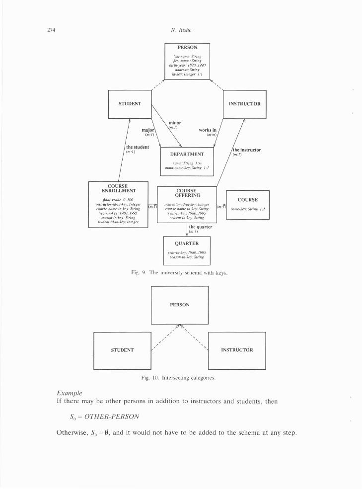
Example The binary schema of the university application has been converted so far into the schema in Fig . 9.
5.3. Disjointness of categories
Step 2 . Convert the intersecting abstract categories into disjoint categories by the following procedure for every group of intersecting categories.
Example Figure 10 contains a group of three intersecting categories . The categories STUDENT and INSTRUCTOR share an intersection .
(A) Consider a complete group of categories so that every category outside the group is disjoint from every category in the group .
Let C denote the union of all the the categories in the group. If such a category C does not already exist in the schema, then add it. Let S1, S2 , • • . , S" be the other categories in the group. (All of them are direct or indirect subcategories of C.)
Example C = PERSON, S 1 = INSTRUCTOR, S2 = STUDENT.
Let II
S0 = C - US; . i = l
S0 is the hypothetical category consisting of the objects of C which do not belong to any of the subcategories. The category S0 is considered in order to ensure that no information is lost during the conversion . It is not added to the schema at this time. It may or may not be added to the schema at a later step , depending on decisions made at that step.
274
' ....--------<
STUDENT
final-grade : 0 . .100 instructor-id-in-key: lnttger courst-namt-in-key: String
year-in-key: 1980 .. 1995 stason-in-lcty: String
studtnt-id-in-kty: Integer
m:
N. Rishe
PERSON
/ast-namt: String first-name : String
binh-year: 1870 . .1990 address: String
id-key: lnlt'gtr I ·J
namt: String 1 :m nwin-namt-key: String I : I
COURSE OFFERING
instructor-id-in-key·tmegt'r courst-namt-ill-kty: String
year-in-kty: 1980 .. 1995 Sfason-in-key: String
the quarter (m:l)
QUARTER
year-m-key: 1980 .. 1995 uason- in -key: String
INSTRUCTOR
COURSE
name-kty: String I :I
Fig. '!. The uni versity schema with keys.
STUDENT
Example
' / '
' ' '
PERSON
' ' ' ' ' ' ' '
Fig. 10. Inte rsecting ca tegori es.
INSTRUCTOR
If there may be other persons m addition to instructors and students, then
S0 =OTH ER-PERSON
Otherwise, S0 = 0, and it would not have to be added to the schema at any step.
Top-down relational DB design 275
In the continuation of this case study in the examples we will assume the latter case: S0 = 0, i.e. the database allows no persons other than students and instructors.
(B) Estimate the intersection factors L and p. In order to choose the best way of conversion, we shall need to estimate the following quantities.
Example For the above group of intersecting categories, the choice of the method to eliminate the intersection of the categories will depend on the correlation of two parameters: • the percentage of people who are both students and instructors, L, and • the percentage of relationships specific to students or instructors among all the
relationships which can be relevant to persons, p.
number of relationships whose domain or range is S1 or··· or S, p = number of relationships whose domain or range is Cor S1 or ··· or S,
Example
For the group of the previous examples, p = 150
.
expected total number of objects in the intersections L=
expected total number of objects in C
In other words,
expected cardinality of U (S; n S) i ¢ j
L = -----------'-----expected cardinality of C
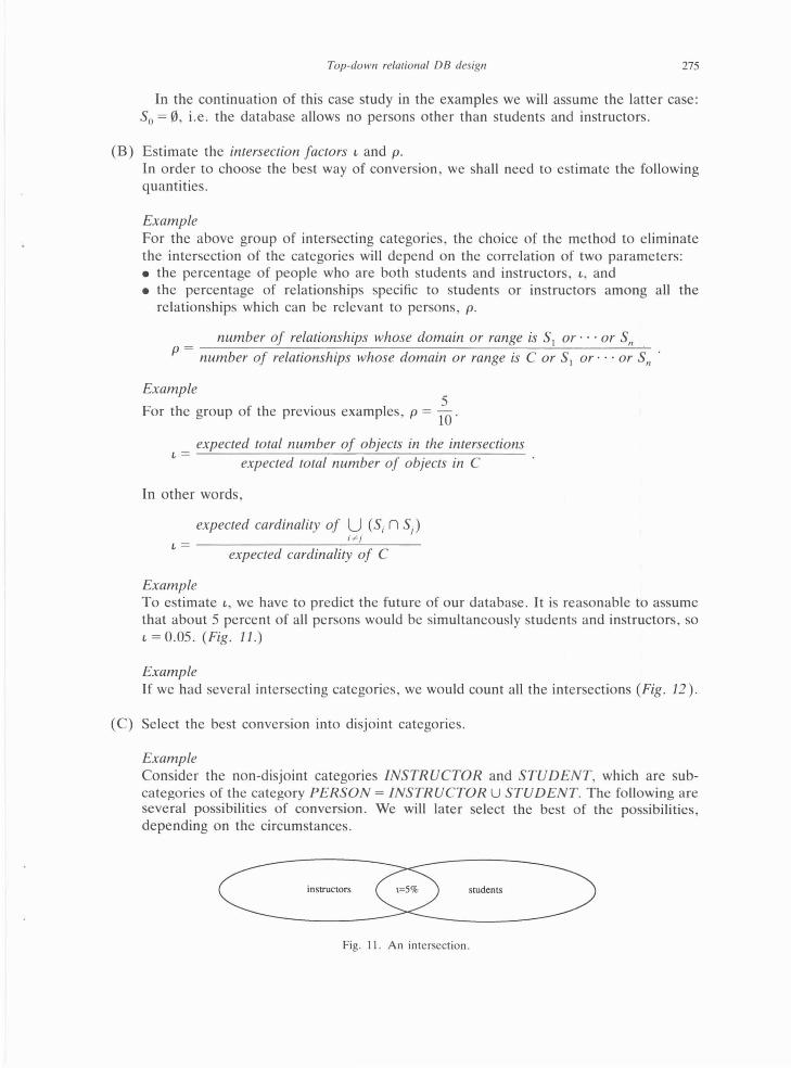
Example To estimate L, we have to predict the future of our database. It is reasonable to assume that about 5 percent of all persons would be simultaneously students and instructors , so L = 0.05. (Fig. 11.)
Example If we had several intersecting categories, we would count all the intersections (Fig . 12).
(C) Select the best conversion into disjoint categories.
Example Consider the non-disjoint categories INSTRUCTOR and STUDENT, which are subcategories of the category PERSON = INSTRUCTOR U STUDENT. The following are several possibilities of conversion. We will later select the best of the possibilities, depending on the circumstances.
instructors students
Fig. II. An intersection.

276 N . Rishe
instructors students
alumni staff
Fig. 12. Four intersecting categories .
(a) Conversion into one category (Union)
Example Substitute the whole group of categories by their union, the category PERSON. This category will serve as the domain or the range for all the relationships whose domain or range was one of the original categories. In addition, this category will have two Boolean attributes , /S-AN-INSTRUCTOR and IS-A-STUDENT, associating the value true with objects representing instructors and students respectively (Fig. 13 ).
(b) Conversion into artificially disjoint categories of Hats
Example Substitute these categories by two disjoint categories of hats: Hat-of-a-STU DENT and Hat-of-an-INSTRUCTOR (usually abbreviated just STUDENT and INSTRUCTOR, but the meaning of the full names is intended).
An instructor who is also a student will be represented by two distinct objects of the aforementioned categories.
The objects of the new categories are not persons, but rather their 'hats'- a person may have two 'hats' , one as an instructor and one as a student. The two categories of 'hats' are disjoint.
The relationships whose domain or range is the category PERSON, for example the relationship ADDRESS, will be replaced by two relationships having the new categories as their domains or ranges, such as the relationships STUDENT'S-ADDRESS and INSTRUCTOR' S-ADDRESS. (Fig . 14.)
PERSON
id-key: Integer I : I la.st-namt : Srring
fi rst-name: String birth·ytar: 1870 .. 1990
addrns: String is-a-swdent: Booli'an
iS-GIJ -illstructor: Boo/ta11
0 major - relationship from PERSON to DEPARTMENT (m: /)
D minor - relationship from PERSON to DEPARTMENT (m: /)
0 the-instructor- relationship from COURSE·OFFERING to PERSON (m :l )
0 the-student - relationship from COURSE·ENROLLMENT to PERSON (m: l )
D works-in - relationship from PERSON to DEPARTMENT (m:m)
Fig. 13. Category PERSON and its relations.
i

Top-down relational DB design
STUDENT
id-kry: lnttger I :1 last-name: String first-namt : String
hirth-yrar: 1870 . .1990 addrtss: Siring
INSTRUCfOR
id-kry: lntrRer 1:1 las1-namt: String first-namt : String
hirth-ytar: 1870 .. 1990 addrns: String
Fig. 14. Attributes moved from PERSON to STUDENT and INSTRUCTOR.
277
It may appear that by introducing the categories of 'hats' we have succeeded in defeating the system . Actually , we have fooled ourselves. Without understanding the relationship between two hats of one person , the system will not be able to correctly interpret some queries of naive users, and may cause inconsistency in the stored information and other problems: - When the address of a person is updated, it may get updated in one category, but not in
the other. The database will become inconsistent. -A naive query like 'How many people are there?' will involve double count of persons who
are instructors and students simultaneously.
(c) Conversion into Union + Hats: we can retain the union category with its original relations and in addition have the hat categories to hold relations specific to the former subcategories.
Example We can retain the category PERSON with all its relationships and define two categories of hats which will inherit all the relationships of STU DENT and INSTRUCTOR , and additionally will have keys and special 1: 1 relationships with the category PERSON (Fig. 15).
Example To further explore the differences between the three approaches, consider the formulation of the query 'Print the names of all the students.'
Hats: get s.LAST-NAME
where s is a STU DENT Union:
get s.LAST-NAME where
sis a PERSON and s.JS-A-STUDENT
Union + Hats: get p.LAST-NAME
where p is a PERSON and exists sin STUDENT:
s.ID-key = p.ID-key
Relative disadvantages of each approach The principal disadvantage of Hats is the redundancy. For example, the birth-year of an
instructor who is also a student has to be logically represented twice in the database, which can cause inconsistency and other problems.

278 N. Rishe
PERSON id-key: Integer
la.H-name: String (and other
relationships of PERSON)
A Hat of a Hat of an STUDENT INSTRUCTOR
id-key: Integer id-key: Integer
other other relationships relationships of STUDE{'{f of IN~TRUCTOR
D PERSON - category (retains its relationships from the binary schema)
D Hat-of-a-STUDE{'{f - category (inherits all the relationships of STUDENT)
D Hat-of-an-INSTRUCTOR - category (inherits all the relationships of INSTRUCTOR)
D student-person- rel ationsh ip from Hat-of-a-STUDE{'{f to PERSON (l:l,roral)
D instructor-person - relationship from Hat-of-anINSTRUCTOR to PERSON (I: /.total)
Fig. 15 . The category PERSON in addition to the categories of hats.
The principal disadvantages of Union are the unnaturalness of the schema and the under-coverage of integrity constraints. For example, an additional integrity constraint has to be defined to prevent association of a non-student instructor with a major department of studies. Another important deficiency is the null-values , causing significant problems in formulation of queries . (We say that 'p.MAJOR is null ' if the person pis not related to any department by the relationship MAJOR.)
The principal disadvantages of Union + Hats are the unnaturalness of the schema and significant difficulties in the formulation of queries and other operations. These difficulties , however, can be overcome by the use of user-views which would conveniently redefine the concepts of the schema. This requires that the DBMS provide a high level support for user-views , including the capability to specify updates through user-views . Most relational DBMS , however, do not provide sufficient support of user-views.
Conclusion Unless the DBMS provides sufficient support for user-views as discussed above, we have
to exclude the Union+ Hats approach. Both other approaches, Union and Hats, would result in low-quality schemas, but the
relational database designer has to choose the better of the two.
Example The choice should usually depend on the correlation of two parameters: the percentage of people who are both students and instructors , t , and the percentage of relationships

Top-doiVn relational DB design 279
specific to students or instructors among all the relationships which can be relevant to persons, p.
The relative redundancy in Hats increases when L increases and when p decreases. The unnaturalness and the undercoverage of constraints in Union increase when L decreases and when p increases .
The following provides a decision criterion for an arbitrary group of categories. The decision is made according to the L: p ratio. When this ratio is relatively high then the Union approach would usually be preferable.
When there is a chain of sub-sub-categories, the approach Hats becomes too complicated, and is not recommended. It is however the most natural approach in the majority of situations, because in the majority of cases L is small, the subcategory hierarchy is rather flat (no sub-sub-categories) , and the DBMS does not provide sufficient support for user-views.
(D) Convert the group of categories into disjoint categories. (a) if the DBMS provides a high level support for user-views , including specification of
updates, then (Union + Hats): (i) Substitute every direct or indirect subcategory S of C in the schema being
converted by the category Hat-of-a[n]-S. Each object in this new category is an event of membership in the category S, that is, if xis an S then 'xis an S' is one element in Hat-of-an-S. (The categories of hats are disjoint. For simplicity , the former names S may be kept but the new meaning is assumed.)
Example
0 [ Hat-of-a-]STU DENT- category 0 [Hat-of-an-]INSTRUCTOR- category
Example If we also had
0 TENURED-FACULTY -subcategory of INSTRUCTOR
then we would convert it into
0 Hat-of-TENURED-FACULTY- category
(ii) Retain the category C.
Example
0 PERSON- category
(iii) Connect every new category of hats S to each immediate supercategory of S by a new relationship. Specify integrity constraints that these new relationships are one-to-one and total.
Example
0 student-person- relationship from Hat-of-a-STU DENT to PERSON to PERSON (1: 1, total)

280 N. Rishe
(iv) Let every new category of hats S have all the relationships that the former category S had .
Example
0 major- relationship from Hat-of-a-STUDENT to DEPARTMENT (m: 1)
(v) Specify and add a key for every category of hats S. The simplest way to do this is to inherit the key of C.
Example
0 id-key- attribute of Hat-of-a-STUDENT, range: Integer (1: 1)
(b) else if t ip is high' or there is a chain of sub-sub-categories then (Union): (i) Replace the whole group of categories by one category C.
Example
0 PERSON- category
(ii) Bring all the relationships exiting or entering the former subcategories to C.
Example
0 the-student- relationship from COURSE-ENROLLMENT to PERSON (m: 1)
(iii) Add to C total Boolean attributes named is-a(n]-S for every direct and indirect subcategory S of C in the schema being converted.
Example
0 is-a-student- attribute of PERSON, range: Boolean (m: 1, total ) 0 is-an-instructor- attribute of PERSON, range: Boolean (m: 1,
total)
(iv) Add an integrity constraint stating that any object of C may participate in a former S's corresponding relationship only if the respective function is-an-S gives true.
Example
for every p in PERSON: if exists d in DEPARTMENT: p WORKS-IN d then p.IS-AN-INSTRUCTOR
'' High' is relative, a quan titative measure is the designer's decision. In a practical design of databases with over a hundred categories, the author has applied the threshold of t: p = 0.6 in most instances.

Example
Top-down relational DB design
for every pin PERSON: if not (p MAJOR null) then p.IS-A-STUDENT
281
(v) Whenever there are attributes is-an-S1 and is-an-S2 , where S, is a subcategory of S2 in the original schema, add a constraint enforcing that in terms of the new attributes.
Example If we had:
0 UNDERGRADUATE- subcategory of STUDENT
then we would add a constraint:
for every sin PERSON: if s.IS-AN-UNDERGRADUATE
then s.IS-A-STUDENT
(vi) Whenever there are attributes is-an-S, and is-an-S2 , where S, and S2 are disjoint in the original schema, add a constraint enforcing that in terms of the new attributes .
Example If the category UNDERGRADUATE was disjoint from the category INSTRUCTOR, then we would add a constraint:
(c) else (Hats):
for every s in PERSON: if s .IS-AN-UNDERGRADUATE
then not (s.IS-AN-INSTRUCTOR)
(i) Substitute the categories S,, ... , S" by the corresponding n categories Hat-of-aS1, . . . , Hat-of-a-S" of the events of the membership in categories, that is , if xis an Si then 'x is an S;' is one element in the category Hat-of-an-Si. (The categories Si are disjoint. For simplicity, former names Si may be kept but the new meaning is assumed.)
Example
0 Hat-of-a-STUDENT- category
disjoint from
0 Hat-of-an-Instructor- category
(ii) If there are , or may be in the future, objects in C that do not belong to any of the subcategories S, , .. . , S" , then add a new category S0 to the schema.

282 N. Rishe
This will be the category of the objects that do not belong to any of the subcategories. This category is usually called other-C.
Example
0 OTHER-PERSON- category.
(iii) Replace every relationship R whose domain or range is C, by a relationship of the same name, but having the categories S, as their domains or ranges. (The relationship R is partitioned into several relationships according to the restricted domains or ranges S;.)
Example
0 birth-year- attribute of Hat-of-a-STU DENT, range: 1870 .. 1990 (m: 1)
(iv) Eliminate the category C. (v) Specify integrity constraints to prevent inconsistency of the redundant infor-
mation: key values as an object y of the category Hat-of-an-S1, then the other relationships of C (inherited by the categories of hats) must be equal for x and y.
Example We choose this alternative (Hats) for the intersecting group of the subcategories of PERSON in the case-study database.
The schema now has redundancy, which should be controlled by an integrity constraint, if possible. The integrity constraint is
for every sin Hat-of-a-STUDENT: for every i in Hat-of-an-INSTRUCTOR:
if (s. ADDRESS =Pi. ADDRESS or s.LAST-NAME =P i.LAST-NAME or s. FIRST-NAME =P i.FIRST-NAME or s.BIRTH-YEAR =P i.BIRTH-YEAR)
then s .I D-key =P i.1 D-key
(Note The constraint could have been written without negations, 'in a positive spirit', but then the meaning of the absent values could be misinterpreted.)
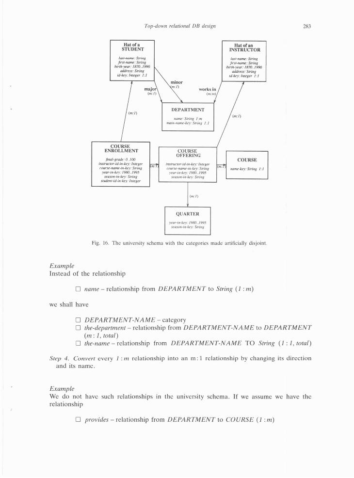
Example The semantic schema of the university application has been converted so far (by Hats) into the schema in Fig. 16.
5.4. Removal of relationships
The steps of this section complete the process of schema conversion. Step 3. Convert every proper I : m or m: m relationship whose range is a concrete category
into a new abstract category with its two functional relationships through a relationshipsplit.
Example
Top-down relational DB design
Hat ora STUDENT
last-nan~: String first-no~ : String
id-key: lnttgu 1:1
birth-year: 1870 .. /990 ~ addrtss: String
works in (m:m)
(m:J)
COURSE ENROLLMENT
final-gradt: 0 .. 100 instruciOr-id-in-lcty: fnttgtr courst-namt-in-kty: String
year-in-key: 1980 .. 1995 stason-in-kty: String
studtnt-id-in-lcty: lnttger
DEPARTMENT
namt>: Smng 1 :m nUJtll·l/anu•-key: String I : I
COURSE OFFERING
instrucwr-td-in-k.ey: lnttgtr course-namr-in-lr.ey: String
year-in-let')'' 1980 .. 1995 St'OSon-111-lct>y- String
(m: /)
QUARTER
)'t'Uf·lll·kt•y: /980 .. / 995 season-in-key: String
Hatofan INSTRUCfOR
last-na~tW: String first-norM: String
birth-year: 1870 .. 1990 addrtss: String
id-key: lnttgu I :I
(m :l)
COURSE
Fig. 16. The unive rsity schema with the categories made a rtificially disjoint.
283
Instead of the relationship
D name- relationship from DEPARTMENT to String (1: m)
we shall have
D DEPARTMENT-NAME- category D the-department - relationship from DEPARTMENT-NAME to DEPARTMENT
(m: 1, total) D the-name- relationship from DEPARTMENT-NAME TO String (1: 1, total)
Step 4. Convert every 1 : m relationship into an m: 1 relationship by changing its direction and its name .
Example We do not have such relationships m the university schema. If we assume we have the relationship
D provides- relationship from DEPARTMENT to COURSE (1: m)
284 N. Rishe
Then we would change it into
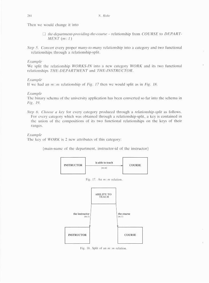
D the-department-providing-the-course- relationship from COURSE to DEPARTMENT(m:J)
Step 5. Convert every proper many-to-many relationship into a category and two functional relationships through a relationship-split.
Example We split the relationship WORKS-IN into a new category WORK and its two functional relationships THE-DEPARTMENT and THE-INSTRUCTOR.
Example If we had an m: m relationship of Fig. 17 then we would split as in Fig. 18.
Example The binary schema of the university application has been converted so far into the schema in Fig. /9.
Step 6. Choose a key for every category produced through a relationship-split as follows. For every category which was obtained through a relationship-split, a key is contained in the union of the compositions of its two functional relationships on the keys of their ranges.
Example The key of WORK is 2 new attributes of this category:
{main-name of the department, instructor-id of the instructor}
is able to teach INSTRUCTOR COURSE
(ru-m)
Fig. 17. An 111: m relation.
ABILITY TO TEACii
the instructor the course (m : l) (m : l )
INSTRUCTOR COURSE
Fig. 18. Split of an m: m relation.

Top-down relational DB design
DEPARTMENT NAME
STUDENT
COURSE ENROLLMENT
fina/- gradt : 0 .. / 00 in.structor-id-in-k.ty: lnttgtr courst-namL-in-kty: Siring
ytar-in-kry: 1980 .. 1995 stason-in-k.ty: String
studtm-id-in-k.ty: lnrtgtr
tht-name : String
m:
(m:l)
DEPARTMENT
main-namt-kty: Srring I :1
COURSE OFFERING
instructor-id-in-kty: lnttgtr courst-nan~-in-kty: String
y•ar-in-kty: / 980 .. 1995 stason-in-kty: String
(m : l)
QUARTER
ytar-in-kty: 1980 . .1995 stason-in-kty: Srring
WORK
INSTRUCTOR
last-namL: String first-naml! : String
birth·ytar: 1870 . .1990 addrtss: String
id·kty: lnltgtr 1:1
COURSE
naml!-kty: String I :1
Fig. 19. The university schema after all the relationship splits have been performed.
Example The key of DEPARTMENT-NAME is contained tn
{the-name, main-name of the department}
Since the-name is 1:1 , the key of DEPARTMENT-NAME is {the-name}.
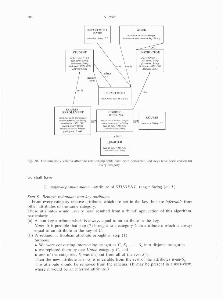
Example
285
The binary schema of the university application has been converted so far into the schema in Fig. 20.
Step 7. Replace every m : 1 relationship f whose range is an abstract category by the composition off on the chosen key of its range, that is , by attributes b P ... , b n, where x.b1 = (x.f).a" and a 1, •• • , an is the chosen key off's range .
Example Instead of
0 major- relationship from STUDENT to DEPARTMENT (m: 1)
286
STUDENT
COURSE ENROLLMENT
instrurtor-id-in-kty: Integer coursr-namt-in -k.ty: String
year-in-ke}" 19/JiJ .. / 995 stason-in-lcty: String
siUdtnt-id-in-k.ey · fnttger final-gradr : 0 .. 100
N. Rishe
DEPARTMENT NAME
WORK
name-key: Siring /"J tnstructor-id-in-key: Integer
deparimttll-nUJill-name-in-key: String
m:
DEPARTMENT
mau~-twnu•-kt•y : String 1 ·J
COURSE OFFERING
instrurrnr-td-m-kt•y: ltllt',~t'r COIIr!it-namt-in-kry · Strmg
year-in-kry: /9/Ji) 1995 seascm-tn -key: Strmg
(m: / )
QUARTER
year-in-key: 19/JiJ .. / 995 seasnn-in-kt•y: Stnng
INSTRUCTOR
id-kty: lnltgtr 1:1 last-no~ : String first-no~ : String
binh-ytar: 1870 .. 1990 address: String
COURSE
namt-kty: String I : I
Fig. 20 . The university schema after the relationship splits have been performed and keys have bee n chosen for every category.
we shall have
0 major-dept-main-name- attribute of STU DENT, range: String (m: 1)
Step 8. Remove redundant non-key attributes. From every category remove attributes which are not in the key , but are inferrable from
other attributes of the same category. These attributes would usually have resulted from a 'blind ' application of this algorithm, particularly (a) A non-key attribute which is always equal to an attribute in the key .
Note: It is possible that step (7) brought to a category Can attribute b which is always equal to an attribute in the key of C.
(b) A redundant Boolean attribute brought in step (1): Suppose • We were converting intersecting categories C, 5 1, ••• , S, into disjoint categories, • we replaced them by one Union category C, and • one of the categories S; was disjoint from all of the rest S/s. Then the new attribute is-an-S; is inferrable from the rest of the attributes is-an-Si. This attribute should be removed from the schema. (It may be present in a user-view , where it would be an inferred attribute.)
Example If we had
Top-down relational DB design 287
0 ILLITERATE- subcategory of PERSON (disjoint from INSTRUCTOR and from STUDENT)
and furthermore, there were no other persons but students, instructors , and illiterate persons , then the attribute is-illiterate would be derivable:
for every p in PERSON: p.IS-ILLITERATE =
(not p .IS-A-STUDENT and not p. IS-AN-INSTRUCTOR)
Note: The removal of several attributes should not be performed simultaneously. Otherwise , two attributes mutually inferrable, but not inferrable from the rest , might be removed.
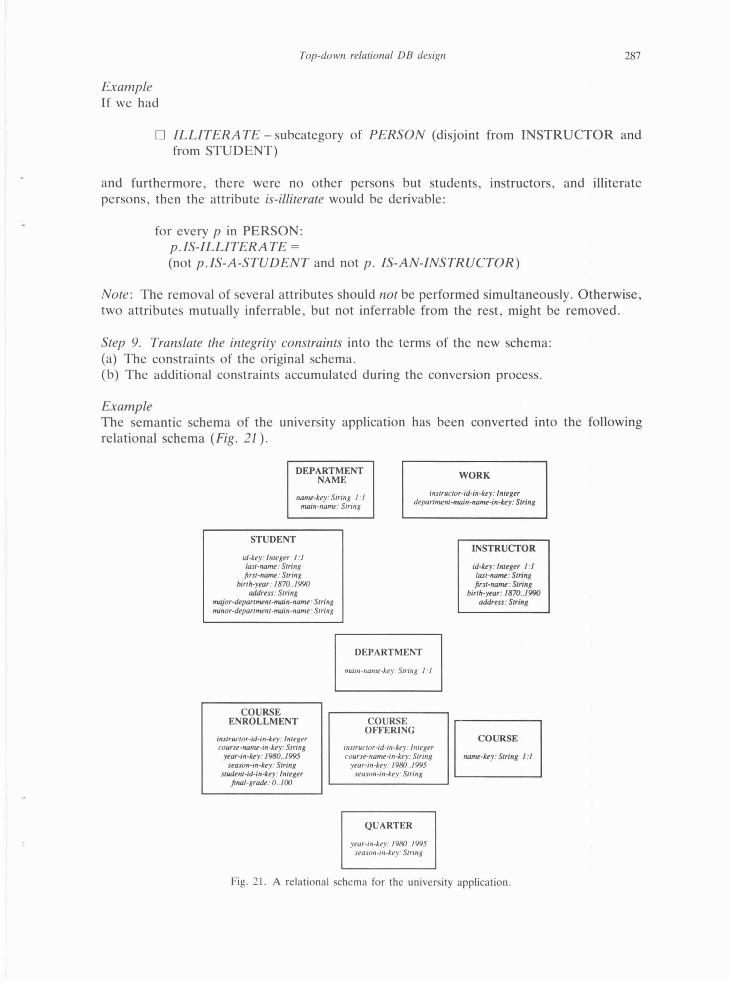
Step 9. Translate the integrity constraints into the terms of the new schema: (a) The constraints of the original schema. (b) The additional constraints accumulated during the conversion process.
Example The semantic schema of the university application has been converted into the following relational schema (Fig. 21 ).
DEPARTMENT NAME WORK
nam~~key: String I :I main-natnL: String
instruciOr-id-in-kty: lnttgtr department-main-na~-in-kty: String
STUDENT
id·kty: lnttgtr 1:1 last-llllmi' : String first-nanu : String
birth-ytar: 1870 .. 1990 addrtss: String
major-drpartnvnt-main-namt: String minor-dtpartmtnt-main-namt: String
COURSE ENROLLMENT
instruc/o r-ld-in-kry: lnttg t r couru-nanu-in-by: String
year-in-kty: 1980 .. 1995 stason-in-kty: String
studtnt-id-in-lcty: lnttgtr fi110/-gradt: 0 .. 100
DEPARTMENT
moin-namt-key: String 1:1
COURSE OFFERING
instrurtor-id-in-kty: lnttgtr courst -namt-in-kty: String
year-in-kty: 1980 .. 1995 uason-in-key: String
QUARTER
year-in-key: 1980 .. 1995 season-in-kry: Siring
INSTRUCTOR
id-kty: lnttgu 1:1 last-no~: String first-no~ : Siring
birth-ytar: 1870 .. 1990 address: String
COURSE
IIOmt-kty: String I : I
Fig. 21. A relational schema for the university application.

288 N. Rishe
6. The tool
We have implemented a tool which automates all the busy work of the methodology and provides graphic output. With respect to the intelligent design decisions, the tool accepts instructions from its user, who is a database designer, or, when the user defaults, makes decisions itself based on 'rule-of-thumb' principles.
This tool is based on pipeline database design principles: the semantic description of an enterprise is processed by a series of filters, changes in the semantic description are automatically propagated. The input consists of the listing of a linear description of the semantic schema, including the definitions of the meanings of all the categories, relationships, and attributes, integrity constraints at the semantic level, designer's choices for the conversion decisions, and overwrites to be modified in the resulting relational schema. The input consists of sections , each forming a logical subschema. The subschemas are interconnected by common categories. The output of the tool consists of: (I) Logical design report. This report is independent of the DBMS to be used for the
project. (a) Graphical semantic subschemas and definitions of all of their concepts. (b) Summary of the semantic schema. (c) The relational schema and its integrity constraints. (d) Glossary, defining the meaning of all the application's attributes and tables. (e) Miscellaneous analysis. (f) A comprehensive index.
(2) An ORACLE database , including: (a) SQL definitions for all the tables , attributes, comments to the attributes (derived
from the comments to the meaning in the semantic schema), keys , referential integrity specifications, specifications of checks to be performed on attribute values.
(b) Generation of screen data entry and update forms, including triggers to enforce integrity. For every table there are two forms: (i) a base form covering all the attributes of the table; (ii) as above, but also containing sub-windows for all the dependent tables connected to this table by 1 : m relationships, i.e. the tables having referential integrity pointers to this table.
(c) A generator of default reports . This tool has been used for database design for the Everglades National Park.
Example A sample logical declaration of an attribute line in the input of the Everglades schema is:
attr location-tolerance HYDROLOGY-STATION 0 .. 1000 m: 1 (Tolerance of the location of a station, in feet. A value X assigned to this attribute means that the tolerance is +/-X feet.)
Most of the above is a comment defining the meaning of the attribute. (This comment is automatically propagated to data-entry windows, reports , glossaries, etc.)
The input declarations are maintained in flat files using a text editor. Graphic depictions are automatically generated. Some other approaches prefer graphical input interface. In this tool , we prefer a textual input interface while leaving the pictures for automatic generation by the tool. This allows greater flexibility and saves time. About 80% of the input is the text of the comments that are logical definitions of categories and relations. It is easier to maintain such comment texts using a text editor than using a graphic tool. Also , input hardware independence is achieved: any terminal and a modem will do.
Top-down relational DB design 289
Apart of the design pipeline, the input files are subjected to other tools like spellers, searchers, and publishing systems.
This tool has been implemented at the Florida International University on a SUN-4 computer running a UNIX-compatible operating system. The programs were written mostly in the C language. The database design descriptions are automatically produced in a publication ready form using the DITROFF text processing package . On-screen graphic output is generated in POSTSCRIPT. The current DBMS interface is to the ORACLE system.
7. This methodology vs. normalization
The normalization is a methodology for the design of relational databases that has been quite popular in the academic world. However, it has not been widely used in the application industry. One of the reasons for the lack of popularity in the industry was the mathematical sophistication of the normalization methodology.
This is a 'bottom-up' methodology. The design proceeds as follows. First, a poor relational schema is designed directly from the requirements . Then, the schema is refined in steps by eliminating certain aspects of redundancy (and thus potential inconsistency and update anomalies). The schema at every step satisfies certain mathematically defined criteria of non-redundancy corresponding to the step. These criteria are called normal forms corresponding to the steps. • The normalization methodology captures only a few of the aspects of the database
semantic quality , while the methodology suggested in this paper attempts to capture all the aspects.
• The normalization methodology is too difficult to be used by most systems analysts and software engineers.
• The normalization methodology is 'bottom-up': a 'bad' data base is considered to be the starting point , and then it is refined by normalization. This is analogous to writing a bad program and then improving its structure. This paper's methodology is ' top-down' : good semantic schemas are designed first, and then they are downgraded to meet implementational restrictions , while the original semantic schemas remain to serve as documentation. This is analogous to writing an algorithm first , and then translating it into a structured program, while the algorithm remains as documentation. In general, this is the advantage of going from conceptual design into logical design . Other approaches exist along the same lines , e.g. [34].
Acknowledgment
The author is very grateful to Dr. Sham Navathe, whose detailed comments and suggestions have resulted in significant improvement of this paper. The author thanks the anonymous referees for their valuable input. The author is also grateful to his students who implemented the tools: Alok Jain, Carlos Ibarra , and Tim Riley .
References
[I] J .R . Abrial, Data semantics, in: J.W. Klimbie and K.L. Koffeman , eds. , Data Base Management (North-Holland, Amsterdam. 1974) .
[2J R. Hull and R. King, Semantic data models , ACM Comput. Surveys 20(3) (1987) 153-189.
[3] J. Peckham and F. Maryanski. Semantic database

290 N. Rishe
modeling: Survey. appl ications. and research issues. ACM Complll . Surveys 19(3) (1988) 201 -260.
[4] N. Rishe, Database Design: The Semantic Modeling Approach (McGraw-Hill. New York, 1992).
[51 N. Rishe, On representation of medical knowledge by a binary data model. J. Math. Comput. Modelling 8 (1987) 623-626.
161 N. Rishe, Database Design Fundamentals: A Struc/Lired flllroduction to Databases and a Stmctured Database Design Methodology (PrenticeHall. Englewood Cliffs. NJ . 1988).
171 N. Rishe. Semantic database management: From microcomputers to massively parallel database machines. Keynote Paper. Proc. Sixth Symp. on Microcompwer and Micorprocessor Applications. Budapest (Oct. 17- 19. 1989) 1- 12.
[81 N. Rishe. Semantic binary database model , Hong Kong Complll. J. 6( II) ( 1990) 30 - 34.
191 G . Bracchi. P. Paolini and G. Pelagatti, Binary logical associations in data modelings. in: G. M. Nijssen. ed .. Modeling in Data Base Management Systems . IFIP Working Conf. on Modeling in DBMSs (1976).
[101 G.M . Nijssen, Current issues in conceptual schema concepts. in: Architecture and Models in Data Base Management Systems (North-Holland. Amsterdam. 1977).
1111 G.M. Nijssen, An arch itecture for knowledge base systems, Proc. SPOT-2 Con[.. Stockholm ( 1981).
11 21 B. Breutman. E. Falkenberg and R. Mauer. CSL: A Conceptual Schema Language. Proc. IFIP TC 2 WG 2.6 Working Con[. (March 1979).
[13] M.F. Senko. Fora! LP: Design and implementation. Proc. Very Large Data Base Con[. ( 1978).
[141 L. Mark, What is binary relationship approach? Entity-Relationship Approach to Software Engineering (North-Holl and. Amsterdam. 1983).
1151 L. Mark, Defining views in the binary relationship model. Inform. Syst. 12(3) (1987).
[1 6] L. Mark. A graphical query language for the binary relationship model, Inform. Syst. 14(3) ( 1989).
1171 R. Meersman and F. Van Assche . Modeling and manipulating production data bases in terms of semantic nets. 8th Internal. Joint Con[. on Artificial Intelligence. Karlsruhe ( 1983) 325- 329.
1181 D. Yermeir. Semantic hierarchies and abstraction in conceptual schemata. Inform. Syst. 8(2) ( 1983).
119] S. Abiteboul and R. Hull. IFO: A formal semantic database model. Proc. ACM S!GACTS!GMOD Symp . Principles of Database Systems ( 1984).
1201 M. Hammer and D. McLeod. Datahas..: description with SDM: A seman tic database model. ACM Trans. Database Syst. 6(3) (1981) 351 - 386.
[21] L. Kerschberg and J.E.S. Pacheco. A functional
data base model. Tech. Rep .. Pontificia Univ. Catolica do Rio de Janeiro. Brazil. 1976.
[221 D.W. Shipman. The functional data model and the data language DAPLEX. ACM Trans. Database Syst. 6( 1) (1981) 140- 173 .
1231 A. Chan. S. Danberg. S. Fox , W. Lin. A. Nori and D.R. Ries. Storage and access structures to support a semant ic data model. Proc. Eighth !merna/. Con[. Very Large Data Bases, IEEE Computer Society Press . Silver Spring. MD . 1982.
[24[ R. King, SEMBASE: A semantic DBMS. Proc. First Workshop on Expert Database Systems. Univ. of South Carolina (1984) 151 - 171.
[251 G.M.A. Yerheijen and J. Van Bekkum, NIAM An information analysis method. in: Information
Systems Design Methodologies: A Comparative Review. T.W. Olle et al.. eds. (IFIP, NorthHolland . Amsterdam , 1982).
[261 C.M.R. Leung and G.M. Nijssen, From a NIAM conceptual schema into the optimal SOL relational database schema. Aust. Comp111. J. 19(2) ( 1987).
[271 B. Nixon. L. Chung. I. Lauzen , A. Borgida and M. Stanley. Implementation of a compiler for a semantic data model: Experience with taxis. in: Proc. ACM S!GMOD Con[. ACM (1987).
[28] D. Jagannathan. R.L. Guck. B.L. Fritchman. J.P. Thompson and D.M. Tolbert. SIM: A database system based on semantic model. Proc. S IGMOD Internal. Con[. on Management of Data. Chicago (June 1-3. 1988) (ACM-Press. New York. 1988).
[291 S.Y.W. Su and D.H. Lo . A semantic association model for conceptual database design. in: P.P. Chen. eel., Entity-Relationship Approach to Systems Analysis and Design (North-Holland, Amsterdam, 1980) 147- 171.
[30[ S. Su. An object-oriented semantic association model (OSAM *) for CAD / CAM databases . in: A I in Industrial Engineering and Manufacturing: Theoretical Issues and Applications, Soyster and Kashyap, eds. ( 1988).
[311 S. Tsur and C. Zaniolo. An implementation of GEM - Support ing a semantic data model on a relational backend, in: Proc. ACM SIGMOD Internal. Con[. on Management of Data (May 1984).
[32J D.S. Batory . T.Y. Leung and T.E. Wise. Implementation concepts for an extensible data model and data language. ACM Trans. Database Syst. 13(3) (Sep . 1988) 231 - 262.
[331 P. Chen. The Entity-Re lationship Model: Toward a unified view of data , ACM Trans. Database Syst. 1(1) (1976) 9 - 36.
[341 C. Batini. S. Ceri and S.B. Navathe. Conceptual Database Design: An Emity Relationship Approach (Benjamin Cummings. Menlo Park, CA. 1992).
Top-down relational DB design 291
[35] R . Meersman, RIDL: A query system as support for information analysis, ECODO 32 (Sep. 1981 ).
[36[ N. Rishe , Postconditional semantics of data base queries, Lee/Lire Notes in Computer Science, val. 239 (Mathematical Foundations of Programming Semantics. A . ,Melton , ed.) (Springer , Berlin , 1986) 275-295 .
[37] N. Rishe and W. Sun , A predicate calculus language for queries and transactions in semantic databases , in: N. Rishe, S. Navathe and D. Tal, eds., Databases : Theory, Design and Applications (IEEE Computer Society Press, Silver Spring , MD) (1991) 204-221.
[38] N. Rishe, Transaction-management system in a four-generation language for semantic databases , in: Mini and Microcomputers: From Micros to Supercomputers (Proc. ISMM Internal. Con[. on Mini and Microcomputers), Miami Beach (Dec. 14-16, 1988) M.H. Hamza , ed. (Acta Press, 1988) 92-95.
[39] N. Roussopoulos and L. Mark , Schema manipulation in self-describing and self-documenting data models , Internal. 1. Comput. Informal. Sci. 14(1) (1985).
[40] M.L. Brodie, J. Mylopoulos and J.W. Schmidt (eds.), On Conceptual Modelling (Springer, New York. 1984).
[41] R. King and D. McLeod, A database design methodology and tool for information systems. ACM Trans. Office Informal. Syst. 3(1) (1985) 2-21.
[ 42] T.J . Teorey , D. Yang and J.P. Fry, A logical design methodology for relational databases using the extended entity-relationship model. ACM Comput. Surveys 18(2) (1986) 197-222.
[43] P. Shoval, Essential information structure diagrams and database schema design , Informal. Syst. 10(4) (1985).
[44] P. Shoval and M. Even-Chaime, ADDS: A systems for automatic database schema design based on the binary-relationship model. Data & Knowledge Engrg. 2 (1987).
[45] 0. de Troyer and R. Meersman , Transforming conceptual schema semantics to relational database applications, Fourth Scandinavian Research Seminar on Information Modeling and Data Base Management (I986) .
[46] A. Rosenthal and D. Reiner , Database design tools: Combining theory, guesswork, and user interaction , in: F. H. Lochovsky , ed., Emily-Relationship Approach to Database Design and Querying (Elsevier Science Publishers , Amsterdam , 1990) 187-201.
[47] P. Shoval, E. Gudes and M. Goldstein, GJSD: A Graphical Interactive System for Conceptual Database Design, Informal. Syst. 13(1) (1988) .
N. Rishe's publications on databases and rela ted issues include two books (the latest: Database Design: The Semantic Modeling Approach. McGraw-Hill , 1992) and fifty papers. Dr. Rishe chaired the steering and program committees of the PARBASE-90 conference, was the keynote speaker of the JL P-89 conference, and is on the steering committee of the PDIS confer
ence series. Rishe is Professor of Computer Science at Florida International University. Prior to joining FlU in 1987 he held a professorship with the University of California (1984-87). Dr. R1she also has extensive experience in database applications and database systems in the industry. This included eight years of employment as head of software and database projects ( 1976-84) and later consulting for companies such as Hewlett-Packard. Prof. Rishe has a Ph.D. in Computer Science from Tel Aviv University.