a mobile robot combination autonomous behavior strategy
TRANSCRIPT

A Mobile Robot Combination Autonomous BehaviorStrategy Inspects Hazardous Gases in RelativelyNarrow Man-Machine environmentXueshan GAO ( [email protected] )
Beijing Insitute TechnologyQingfang Zhang
Beijing Institute of TechnologyBingqing Lan
Beijing Institute of TechnologyXiaoLong Fu
Xi'an Modern Chemistry Research InstituteJingye Li
Beijing Institute of Technology
Original Article
Keywords: Narrow space, Dynamic obstacle avoidance, Social force model, Fuzzy-PID control, Man-machine environment
Posted Date: May 5th, 2021
DOI: https://doi.org/10.21203/rs.3.rs-453526/v1
License: This work is licensed under a Creative Commons Attribution 4.0 International License. Read Full License

·1·
Title page
A Mobile Robot Combination Autonomous Behavior Strategy Inspects Hazardous Gases in Relatively Narrow Man-Machine environment
Xue-Shan Gao, born in 1966, is currently a professor at Beijing Institute of Technology, China. His main research interests include mobile robot, intelligent robot and rehabilitation robot. E-mail: [email protected]
Qing-Fang Zhang, born in 1994, is currently a PhD candidate at Beijing Institute of Technology, China. Her research interests include mobile robot, intelligent control and intelligent robotics. E-mail: [email protected]
Bing-Qing Lan, born in 1994, is currently a master candidate at Beijing Institute of Technology, China.
E-mail: [email protected]
Xiao-Long Fu, born in 1982, is currently a researcher at Xi'an Modern Chemistry Research Institute, China. His research interests include
unmanned monitoring technology and materials science.
E-mail: [email protected]
Jing-Ye Li, born in 1995. He received his master degree from Beijing Institute of Technology, China, in 2020. His research interests include mobile robot technology. E-mail: [email protected]
Corresponding author:Xue-Shan Gao E-mail:[email protected]

Qing-Fang Zhang et al.
·2·
A Mobile Robot Combination Autonomous Behavior Strategy Inspects Hazardous
Gases in Relatively Narrow Man-Machine environment Xue-Shan Gao1* • Qing-Fang Zhang1• Bing-Qing Lan1 • Xiao-Long Fu2 • Jing-Ye Li1
Received April 22, 2021; accepted March xx, 2021
© Chinese Mechanical Engineering Society and Springer-Verlag Berlin Heidelberg 2017
Abstract: Compared with the public inspection places like airports,
squares, and waiting halls, places such as laboratories, warehouses
are generally relatively narrow, and humans may suddenly appear
in the passages. Once a hazardous or toxic gas leak occurs in such
spaces, it will cause a wide range of casualties and immeasurable
economic losses. To ensure the safety of personal and property,
realize real-time monitoring in unattended or dangerous situations,
a robot moving mechanism with an effective and practical
autonomous behavior strategy is proposed in this paper. Firstly, a
mobile robot equipped with a hazardous gases detector and a high-
definition (HD) industrial camera is designed, which can be
controlled remotely or work autonomously. Next, a fixed-point and
a fixed-trajectory method is adopted to avoidance: establish the
social force model; study the human's (interfering object's) typical
behavior patterns; based on Fuzzy thinking, a dynamic obstacle
avoidance strategy is presented, and combine the dynamic obstacle
avoidance strategy, a combination autonomous behavior strategy
with a Fuzzy-PID controller is proposed. Finally, the crossing
pattern and encountering pattern simulations and experiments
results show that the robot can realize the dynamic obstacle
avoidance in a relatively narrow man-machine environment
smoothly and always maintain a sufficient safety distance to reduce
the "sense of crisis" humans towards the robot. The trajectory
experiments in such spaces verify that when the robot deviates from
the predetermined position during inspection operations, the
combination autonomous behavior strategy can help the robot
return to the target trajectory. Furthermore, compared with the PID
control method, the robot position error up to 0.098m, the angle
error up to 0.088rad, the Fuzzy-PID controller is more stable,
accurate, and fast, which draws the stability and reliability of the
strategy.
Keywords: Relatively Narrow space • Dynamic obstacle avoidance • Social force model • Fuzzy-PID control • Man-machine
environment Xue-Shan Gao
1 Beijing Institute of Technology, Beijing 100081, China
1 Introduction
In the places such as chemical plants, laboratories, warehouses, and other indoor environments, the inspection spaces are relatively narrow. Once a gas leak occurs, it will damage humans, and equipment safety causes heavy casualties and property losses. Therefore, real-time hazardous gases monitoring in unattended or precarious situations in relatively narrow spaces has become one of the most critical problems that need to be solved urgently in emergency and industrial production. The detection range of the fixed detector is fixed and limited, and the hand-held detector cannot ensure the inspector's safety. With the development of robots, the mobile robot has become the focus of scholars at home and abroad [1–3]. Using mobile robots instead of hand-held sensors to detect hazardous gases can reduce operators' risk and ensure that gas leak detection can be completed in real-time and efficiently in unattended situations. However, the typical hazardous gases inspection mobile robots are giant, and dead corners are prone to appear. Besides, the robots generally adopt the method of adjusting the direction and speed of movement to realize dynamic obstacle avoidance. This kind of method is challenging to apply when the robot is in a narrow space with humans.
Dynamic obstacle avoidance technology is an essential technology for the inspection robot [4–5]. The standard algorithms of traditional obstacle avoidance algorithms include Artificial Potential Field (APF) [6], Essential Visibility Graph (EVG) [7], Vector Field Histogram (VFH) [8], and fuzzy logic control et al. [9–11]. In the 1980s, Khatib O [12] proposed an artificial potential field method based on a virtual force field. The planned path generated by it is 2 Xi'an Modern Chemistry Research Institute, Xi'an 710065, China
Novel 6-DOF Wearable Exoskeleton Arm with Pneumatic Force-Feedback for Bilateral Teleoperation
·3·
relatively smooth, and the obstacle avoidance effect is good. However, when the gravitation and repulsion are equal, it will fall into an optimal local solution and produce a concussion route [13]. The vector field histogram proposed by Janet J et al. [14] in the 1990s has high requirements for data storage, which requires the use of sensors to collect data in advance. The reliability of obstacle avoidance is strictly affected by sensor performance [15]. In order to avoid the original defects of the artificial potential field method, Borenstein et al. [16] proposed the VFH vector field histogram method, which verified that the specific candidate direction could successfully guide the robot to deal with the local optimal solution problem in the pure local obstacle avoidance algorithm. However, application occasions are restricted [17]. Fuzzy logic can realize dynamic obstacle avoidance in an unstructured environment [18–19]. This algorithm avoids the construction of complex motion models and environmental data models, could effectively reduce the pressure of data calculation, and improve obstacle avoidance efficiency [20]. Therefore, this research adopts fuzzy thinking to achieve dynamic obstacle avoidance. The main advantage of the design presented in this paper is that it can realize flexible movements and a comprehensive detection in a relatively narrow man-machine space. Through the study of the social force model and the human's typical behavior patterns, this paper proposes a combination autonomous behavior strategy based on the fixed-point and fixed-trajectory method to realize the robot's target inspection mission and ensure humans' and robot's safety.
Besides, to improve controller information transmission accuracy and timeliness, this paper designs a control system. In the 1970s, Scholar Saridis [21] divides the control system into the organization layer, coordination layer, and execution layer based on decreasing control accuracy [22]. With the rapid development of sensor systems and widespread application in robots, a classic three-tier structure of Sense-Panning-Action (SPA) layered architecture emerged [23-24]. However, complete each task requires hierarchical calculation and transmission, resulting in inevitable control delay, lack of flexibility, and real-time. The behavior-based inclusive architecture can avoid long-link information transmission and improve the robot's rapid response functions. The shortcomings include insensitivity to information accuracy, high error rate, and lack of initiative in target tasks exposed due to the lack of task guidance and coordinator plan. This paper adopts a hybrid architecture in the control system's overall design, which can fully reflect the advantages of the above two classic architectures and effectively solve the single structure control limitations.
The research includes five main aspects: 1) Introduce the
robot mechanical structure and composition; 2) Build and analyze the robot kinematics model, establish a social force model, study the human's typical four behavior patterns to help the robot realize dynamic obstacle avoidance, and explain the robot combination autonomous behavior strategy; 3) Design the robot control system; 4) Perform the simulations and experiments; 5) Analyze the simulation and experimental results and draw conclusions.
2 Overall Design of Mobile Inspection Robot
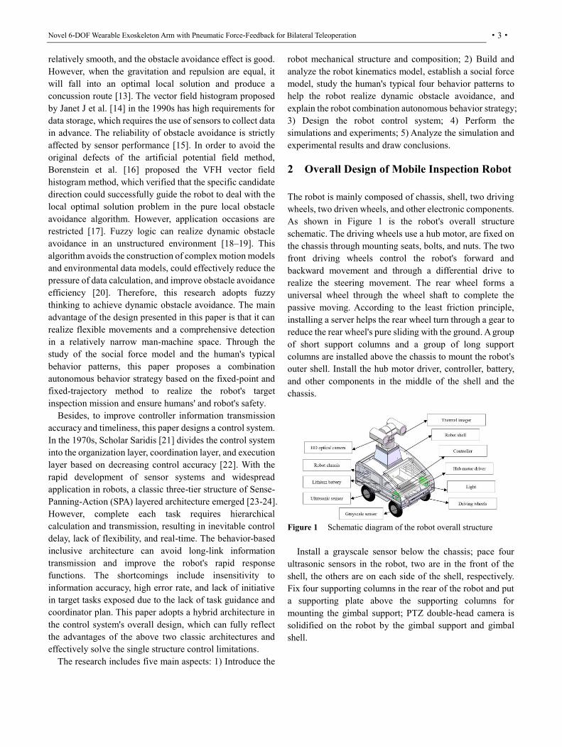
The robot is mainly composed of chassis, shell, two driving wheels, two driven wheels, and other electronic components. As shown in Figure 1 is the robot's overall structure schematic. The driving wheels use a hub motor, are fixed on the chassis through mounting seats, bolts, and nuts. The two front driving wheels control the robot's forward and backward movement and through a differential drive to realize the steering movement. The rear wheel forms a universal wheel through the wheel shaft to complete the passive moving. According to the least friction principle, installing a server helps the rear wheel turn through a gear to reduce the rear wheel's pure sliding with the ground. A group of short support columns and a group of long support columns are installed above the chassis to mount the robot's outer shell. Install the hub motor driver, controller, battery, and other components in the middle of the shell and the chassis.
Figure 1 Schematic diagram of the robot overall structure
Install a grayscale sensor below the chassis; pace four ultrasonic sensors in the robot, two are in the front of the shell, the others are on each side of the shell, respectively. Fix four supporting columns in the rear of the robot and put a supporting plate above the supporting columns for mounting the gimbal support; PTZ double-head camera is solidified on the robot by the gimbal support and gimbal shell.

Qing-Fang Zhang et al.
·4·
3 Kinematics Analysis of the Robot
3.1 Positive Kinematics Model of the Robot In order to establish a robot motion model to analyze the robot kinematics, according to the robot application environment and the robot mechanical structure, the following assumptions are made for the robot system: 1) Assume that the robot chassis is a rigid structure, and the planes of the four wheels are perpendicular to the ground, the center of mass and centroid of each wheel overlap and are in the same plane; 2) Between the two driving wheels and the chassis, between the driven wheel shaft and the chassis, the driven wheel and the driven wheel shaft only exist relative rotation; 3) each wheel only one contact point with the ground and ignores the wheels and tires' slight deformation; 4) Ignore the four wheels' skidding with the ground.
Set the global reference coordinate system {XOY} and the robot reference coordinate system {xoy}, A vector
T
1=[ ]x, y,θ represents the robot pose, take the robot's forward direction as the positive direction. o is at the midpoint of the two wheels,the displacement of the robot on the X and Y axes are x and y, respectively. θ is the angle difference between the global reference coordinate system and the robot reference coordinate system.
Figure 2 Kinematics model of the robot
The rotation speed of the left driving wheels is ω1, the rotation speed of the right driving wheels is ω2, and the radius of the driving wheels is r. The wheelbase of the front and rear wheels is L. The distance from the center of two front wheels to the center of mass is L1. The distance between the rear wheel axis and the center of mass is L2, L3 is the distance from the rear axle to the rotating shaft. The rotation angle of the rear wheel is β. The speed at the midpoint of the two front wheels is v. Figure 2 is the robot kinematics model.
The linear velocity v and angular velocity ω of the body centroid M can be obtained [25–26].
1 2
1 2
+( )
2
( )L
v vv t
v vw t
, (1)
In the global reference coordinate system {XOY}, the M point motion equation is:
1
1
2
cos 0
sin 0
0 1
r cos r cos
2 2
r sin r sin=
2 2
r r
L L
xv
y
, (2)
Paire Eq. (3) each integral:
1 20
1 20
1 20
rcos ( )d
2
rsin ( )d
2
r( )d
L
x t
y t
t
, (3)
When w1 = w2, the two driving wheels' rotation speed is the same, and the robot moves in a straight line. When w1
≠ w2, the robot turns due to the differential speed. When w1 > w2, the robot turns left; when w1 < w2, the robot turns right. When w1 = -w2, the robot rotates in place, and the robot's turning radius is zero. Since the rotation speed of the left and right driving wheels can be set,the robot turning radius is:
1 1
2 2
(1 )L / 2( 1)R
, (4)
As shown in Eq. (5), for this robot, the rotation angle β of the rear wheel is related to the left and right driving wheels' rotation speed ratio, then the rotation angle β is:
31 2
1
321 2
L2(L L ) L tan
cos
L2(L L ) L tan
cos
, (5)

Novel 6-DOF Wearable Exoskeleton Arm with Pneumatic Force-Feedback for Bilateral Teleoperation
·5·
1
3 21 2
1
2
(1 )LL
tan (L L ) /cos
2( 1)
, (6)
r is 200mm, The wheelbase L of this robot in Figure 2 is 438mm, L1 is 214.25mm, L2 is 171.75mm, and L3 is 46mm. According to the formulas above, the greater the rear wheel's turning angle is when the robot turns, the smaller the turning radius.
Considering the robot's driven wheel is not a direct universal wheel but is used as a whole through the combination of two universal wheels. To reduce friction, install two gear with a server to assist the rotation of the rear wheel. When the robot turns 90 degrees, take the data to the formulas above can calculate that the rear wheel's rotation angle is approximately 20 degrees. The rotation speed ratio of the robot's left and right wheels is about 1.44 and the robot's minimum turning radius is about 1.17m, as shown in Figure 3.
Figure 3 Schematic diagram of the robot turning motion
3.2 Dynamic Obstacle Avoidance Strategy
When the robot performs inspection tasks in a narrow indoor space while ensuring that the robot does not collide with interference, especially humans, it should also maintain a reasonable safety range to protect humans from having a "sense of crisis". Therefore, when formulating robot inspection rules, set humans as interfering objects in the shared space. Considering the robot target operating environment and the robot autonomous tracking strategy, adjusting the moving direction is not the best way to avoid obstacles. To improve safety, it finally adopts the fixed-point and fixed-trajectory avoidance methods to obtain appropriate speed control parameters by formulating social force models and fuzzy rules that match the required environment.
3.2.1 Social Force Model
In general, each person and robot will have local motion targets, individual motion speeds, and accelerations in the man-machine behavior model. The following three force items should be considered in the modeling process [27]: 1)
The acceleration term is the trend to reach the desired speed, Facc; 2) The force term reflects the boundary condition of maintaining a certain distance during the interaction between human and robot, Fint; 3) The attractive force term is that the target to human/robot, Fatt.
Assuming that the above three components affect pedestrian decision-making simultaneously, as shown in Figure 4, quoting the traditional force superposition principle, obtain the total effect force Ftotal:
total acc int attF F F F , (7)
The social force model can predict local human motion trends, guide robot behavior strategies to ensure a communication space between robots and humans. Calculate the social space by the following Eq. (8):
, (8)
Rθ,avoid, Rr,avoid are the robot's avoidance distance and the human's avoidance distanc, respectively; m represents the robot's mass; v(t) is the robot moving speed. So far, the social force model between the robot and the human is clear.
Figure 4 Social force model
Furthermore, in 1966, the American anthropologist Dr. Edward Hall summarized interpersonal distance into four types in the works [28]. 1) Intimate Distance. In this range, the intensity of the stimulus is extreme. The other person's sense of existence is intense,divided into 0m–0.15m and 0.15m–0.45m. 2) Personal Distance. This distance is suitable for acquaintances who are in a harmonious relationship to enter. Strangers entering this space will constitute an invasion of others and cause discomfort, divided into 0.45 m–0.75 m and 0.75m–1.2m. 3) Social Distance. A commonly used distance in general working occasions is convenient for handling work tasks,divided into 1.2m–2.1m and 2.1m–3.6m. 4) Public Distance. This space often used
total
,avoid ,avoid
d( )
d m
( )r
Fv t
t
R R v t t

Qing-Fang Zhang et al.
·6·
on very formal occasions, divided into 3.6m–7.5m, more significant than 7.5m. Since the robot is in a narrow indoor environment, to ensure people's sensitive areas, this paper takes the human avoidance range to 1.5m–3m.
3.2.2 Behavioral pattern analysis
According to the man-machine relative distance, relative motion direction, relative position, and relative speed factors in the shared space environment, adopts empirical method and heuristic method to divide the behavior of human (or interfering body) into four typical types [29]: crossing pattern, encountering pattern, leading pattern and confronting pattern. According to different typical behavior patterns, the robot follows the corresponding rules to ensure safety and does not invade sensitive areas.
1) Crossing behavior. In the man-machine coexistence scene, the crossing behavior usually appears at the intersection of the passage, which is an interfering body will cross in the robot's forward direction. 2) Encountering behavior. In this passage scene, the robot and the interfering body will meet face-to-face, and the two motion directions do not affect each other but may enter the sensitive areas of both sides. 3) Leading behavior. The interfering body appears directly in front of the robot, and both sides move in the same direction. 4) Confronting behavior. The interfering body appears directly in the mobile robot, but the two sides move in opposite directions.
To keep the robot motion range in a friendly state with humans and not invade individual sensitive areas, design the above four types of behavior rules based on no collision and no interference.
(a) Crossing behavior
(b) Encountering behavior
(c) Leading behavior
(d) Confronting behavior Figure 5 Four types of behavior pattern
3.2.3 Fuzzy controller
Use the fuzzy logic control method to formulate the interfering objects' behavioral movement rules and robot-specific strategies based on the above analysis of fundamental human behavior patterns. The following three steps are required to make the robot possess decision-making capabilities similar to humans through speed adjustment: fuzzification of input and output, fuzzy reasoning, and defuzzification of output variables. (1) Fuzzification of input and output The input variables include the distance between man and machine, Rr, the interfering object's linear velocity, Vi, and the pattern of interference behavior, Bi. The output is the robot linear velocity increment, ΔVri. The hub encoder can linearly adjust the robot's linear velocity. Except for behavioral patterns, since the domains of these input/output variables are continuous, these variables are continuous. The membership functions can be linearized using Gaussian functions.
When the man-machine distance is less than the robot's maximum avoidance distance, generate the control signal. Nevertheless, the minimum cannot be less than the sensitive human area. Divide the man-machine distance domain into {DS DE DN DF}, where DS stands for sensitive human distance, DE stands for 75% avoidance distance, DN stands for 90% avoidance distance, DF stands for maximum robot avoidance distance, and its membership function as shown in Figure 6(a). Divide the moving linear velocity domain of the interfering object into {VS VF}, and its three language variables represent "fast" and "slow", respectively. Determine the division basis according to the average walking speed of humans. The membership function, as

Novel 6-DOF Wearable Exoskeleton Arm with Pneumatic Force-Feedback for Bilateral Teleoperation
·7·
shown in Figure 6(b). Divide the behavior patterns of interference into {BS BE BL BF}, representing crossing behavior, encountering behavior, leading behavior, and confronting behavior. The membership function, as shown in Figure 6(c). Divide the robot linear velocity increment into {VD VZ VI VR VT}, which represents stop in place. The original set inspection speed is 25%, 50%, 75%, and 100%. The membership function is as Figure 6(d) shows.
(a) Domain of man-machine distance
(b) Domain of linear velocity of interfering object
(c) Domain of pattern of interference behavior
(d) Increment of linear velocity of robot Figure 6 Membership function graph of input/output variable
(2) Fuzzy reasoning
If-then natural sentences based on expert experience and knowledge establish a fuzzy rule library for the above four patterns of behavior rules. Fuzzy reasoning takes the input language as the premise and searches for the rule base's optimal conclusion. Table 1 shows part fuzzy control rules formulated. Connect the input variables Rr, Vi, and Bi with
the logical symbol 'and'.
Table 1 Fuzzy control rule (part)
Man-machine distance
Rr (m)
interfering object's linear
velocity
Vi (m/s)
Interference behavior pattern
Bi
Robot's linear velocity increment
ΔVri (m/s)
DS
DE
DN
DF
VS VF BS
BE
BL
BF
VD
VZ
VI
VR
VT
1 √ √ √ √
2 √ √ √ √
3 √ √ √ √
4 √ √ √ √
5 √ √ √ √
6 √ √ √ √
7 √ √ √ √
8 √ √ √ √
(3) Defuzzification of output variables
The result obtained by fuzzy control rules is a fuzzy quantity, but in actual fuzzy control, the fuzzy quantity cannot directly control the actuator, convert it into a precise quantity. Use the Mandani reasoning method to get the mean value, as in Eq. (9).
1
1
( )=
( )
n
i
n
i
Vri VriVro
Vri
, (9)
ΔVro is the calculated robot linear velocity increment and is the membership function value corresponding to the i element.
3.3 Combination Autonomous Behavior Strategy Then, based on the above analysis and calculation, design the Fuzzy-PID controller to achieve the robot's autonomous movement under the fixed-trajectory. Assume the vector
T
1=[ ]x, y,θ is the robot position vector, v, ω, θ are the robot speed, angular velocity and rotation angle. The vector
T
r r r r=[ ]x , y ,θ is the target position vector of the robot. vr, ωr, θr represent the target speed velocity, target angular velocity and target rotation angle of the robot, respectively. Vector T
e e e e=[ ]x , y ,θ is the robot position error vector. ve, ωe, θe are the errors of robot speed, angular speed and rotation angle, respectively. The robot coordinate error is:

Qing-Fang Zhang et al.
·8·
e r
e e r
re
cos sin 0
= = sin cos 0
0 0 1
x x x
y y y
θ
, (10)
Differential form of position error to get the robot's velocity error and angular velocity error:
e e r e
e e r e
e r
d - cos +
d sin
d
x y v v
y x v
, (11)
To reduce the errors designs the auxiliary kinematics controller based on the robot position error vector:
r e 1 e
r 2 r e 3 r e
cos
sin
v a xv
a v a v y
, (12)
a1, a2, a3 are different auxiliary control parameter respectively, set a1 = -1, a2 = -1.2, a3 = -0.5. Under these auxiliary control rates, v, ω gradually converges to vr, ωr. After getting the robot's linear velocity and angular velocity, the angular speed of the left and right driving wheel ω1,ω2 can be solved.
1
2
1( L) /
2
1( L) /
2
v r
v r
, (13)
To make the errors as miniature as possible, assume angular speed error of driving wheel ωe = e(t), using PID controller, the controller output u(t) can be got [30].
de( )u( ) pe( ) i e( )d d
d
tt K t K t t K
t , (14)
The Fuzzy-PID controller needs to determine the fuzzy relationship between the three parameters Kp, Ki, Kd of the PID controller and the deviation e, the deviation change rate ec. Adjust the three parameters according to the fuzzy control rules through e and ec continuous detection. The parameters are modified online so that the controlled object has good dynamic and static performance.
'
x
'
x
'
x
p= p p
i= i i
d= d d
K k k
K k k
K k k
, (15)
Where, kp', ki', kd' are the initial values of PID parameters; kpx, kix and kdx are the output values of Fuzzy reasoning. Adjust the values of the three PID control parameters automatically according to the movement of the robot.
Use Matlab/Simulink software to design the controller. Divide e, ec and output kpx, kix, kdx into{NB, NM, NS, ZO, PS, PM, PB}, represent negative big, negative medium, negative small, zero, positive small, positive medium, positive big, respectively. The domain is [-3, 3], the membership function of e, ec is 'gaussmf', the membership function of kpx, kix, kdx is 'trimf'. List 49 the Fuzzy control rules.
(a) kpx (b) kix
(c) kdx
Figure 7 Output surfaces of kpx, kix, kdx
The method of 'and' is 'min', the method of 'or' is 'max', the method of 'implication' is 'min', the method of 'aggregation' is max, and the method of 'defuzzification' is 'centroid'. Open the 'Surface', the calculated values of the kpx, kix, kdx are shown in Figure 7.
Establish the Fuzzy logic controller module, set the fuzzification factors ke=0.9, kec=0.1, defuzzification factors k1=3, k2=1, k3=1, the initial values kp'=9, ki'=2, kd'=3. The Fuzzy-PID controller and the motion controller of the robot as shown below.
The two variables e and ec as the fuzzy controller input variables through the fuzzification factors ke and kec respectively, obtain three output variables through the fuzzy rules, and get the values of Kp, Ki, and Kd as output variables

Novel 6-DOF Wearable Exoskeleton Arm with Pneumatic Force-Feedback for Bilateral Teleoperation
·9·
after defuzzification through the factors k1, k2, and k3.
(a) Fuzzy controller
(b) PID controller
(c) Fuzzy-PID controller Figure 8 Fuzzy-PID controller of the robot
Figure 9 Motion controller of the robot
As shown in Figure8 (b), put the e, ec and Kp, Ki, and Kd as the input variables into the PID controller, then it could obtain the optimized deviation value. The integral Fuzzy-PID controller is as shown in Figure 8(c). Establish the robot's motion controller, input the robot's target position vector ξr=[xr,yr,θr]
T to the robot kinematics model, Fuzzy-PID controller and the transfer function, calculate the robot's velocity and angular velocity, then adjust the human-machine pattern through dynamic obstacle avoidance Fuzzy controller, finally obtain the robot's output speed value, as
shown in Figure 9.
4 Control System Structure of the Robot
This part will introduce the robot's corresponding control system within the robot's established overall structure, kinematic model, and moving strategies.
This paper adopts a hybrid architecture in the control system's overall design, a hierarchical architecture as the basic framework, and sub-systems with inclusive characteristics to improve the system's rapid responsiveness and get the overall coordination and decision-making abilities form an organic fusion which could effectively solve the single structure control limitations.
As shown in Figure 10, compose the robot's control system by the perception layer, decision-making layer, and executive layer.
Figure 10 Structure of the robot control system
Raspberry Pi and PC compose the robot's decision-making layer, client and server, respectively. The Raspberry Pi can send and receive control commands and display these commands on the terminal interface through Wi-Fi established by a router. When the camera image data is collected, the image data needs to be hardcoded in H.264 and compressed into the H.264 format video image. The output video image's frame rate should be more than ten frames per second. Therefore, the UDP protocol is selected to improve video transmission efficiency and improve video delay in the transport layer. After receiving the information, the decision-making layer will process and send the information to the executive layer.
The microcontroller unit (MCU) STM32F103 runs the embedded system, sends the motion information of the rotation speed and displacement, and uploads the sensing layer information to the upper computer through serial
Ultrasonic
sensor
Raspberry Pi
4B
STM32F103
PC
HD optical
camera
Left h
ub
moto
r
Serial port
Perception
layer
Decision-
making layer
Executive
layer
Rig
ht h
ub m
oto
r
PT
Z
Wi-Fi
communication
Thermal
imager
TCP/IPclient server
I/O
Telecomm-
unication
Hub motor driver
CAN
Lithium
battery
Lig
hts
Bu
zzer
server
PWM
Grayscale
sensor
Power
supply layer
RS485/Telecomm-
unication

Qing-Fang Zhang et al.
·10·
communication. After receiving the corresponding instruction, drive the hub motor and PTZ to complete the corresponding action. PTZ can rotate 360 degrees in the horizontal direction and -90–90 degrees in the vertical direction. It can be controlled independently of the robot moving mechanism. The monitoring personnel can remotely operate the robot to the target position and control the PTZ platform to observe the real-time indoor situation. Additionally, the MCU can obtain and analyze the ultrasonic sensor's distance information to prevent collision accidents by the internal obstacle avoidance strategy.
5 Simulations and Experiments
5.1 Dynamic Obstacle Avoidance Strategy
The simulation analysis mainly considers the two main behavior patterns of human (interfering object) movement, crossing pattern and encountering pattern, and randomly sets the position of human relative to the robot, the starting and ending movement points according to the behavior pattern. The trajectory of the hollow circle represents the human walking route, and the trajectory of the solid square represents the trajectory of the robot, preset the motion trajectory of the robot as a straight line, the path points are sampled and analyzed with 1s as the unit to make the simulation clear and mark the reference line conveniently. Simulations and experiments are not limited to the experimental parameters used in the design. The speed of the robot and human also can be modified as needed. The experiment platform includes a PC and the robot, and the robot could feedback the real-time measurement data to the PC, as Figure 11 shown.
Figure 11 Experiment platform of the robot
5.1.1 Crossing pattern simulation and experiment
Simulation experiment 1 was considered the typical crossing behavior at the intersection. In this case, the human moved along the set movement route at an initial speed of 0.5m/s, and the robot performed a constant speed inspection work at an initial speed of 0.5m/s. The initial distance between the
robot and the human was about 5.5m. At t = 4.6s, the robot detected an interfering object entering the maximum avoidance distance area from the left side of the robot's moving direction, as shown in the dotted line graphic. At t = 8.6s, as shown by the solid line graph, the robot entered the sensitive human distance and stopped. As shown in Figure 12, in the crossing behavior pattern experiment, the experimenter's initial distance with the robot was about 5.5m. The experimenter crossed from the robot's front left to the front right and kept the average speed of about 0.5m/s. At about 5s, the robot started to decelerate, and until about 9s, the robot waited. When a person passed and left, the ultrasonic sensors detected the distance between the man and the robot. When the data was more significant than the sensitive human distance, the robot's speed accelerated, and finally, the robot detected entered the interference area with the front wall and judged the dangerous distance, and finally stopped.
Figure 12 Trajectory simulation of robot and human in the crossing behavior pattern
(a) Approach robot (b) Robot decelerate to avoid (c) Human leave
Figure 13 Experiment of crossing behavior
5.1.2 Encountering pattern simulation and experiment
Simulation experiment 2 was considered the typical encountering behavior pattern in the aisle. Set the human movement speed to 0.5m/s, and the robot movement speed
Novel 6-DOF Wearable Exoskeleton Arm with Pneumatic Force-Feedback for Bilateral Teleoperation
·11·
was 0.5m/s. As shown in Figure 13, at t=1.6s, the robot detected an intervener entering the maximum avoidance distance area from the robot's moving direction, and the robot decelerated. At t=3.4s, the robot line velocity dropped to zero.
In the encountering behavior pattern algorithm experiment, the experimenter and robot's initial distance was about 5.5m. Then, the experimenter kept a 0.5m/s speed to approach the robot from the front of the robot. In Figure 15(a), the experimenter and the robot were getting closer. At about 2s, the robot started to decelerate; at about 4s, the robot was waiting for human leave. Finally, the person gradually left. When the measurement value was greater than the sensitive human distance, the robot movement speed gradually increased to the initial speed. From the two experimental results, the robot realized obstacle avoidance smoothly.
Figure 14 Simulation of the robot and human obstacle trajectory in encountering behavior pattern
(a) Approach robot (b) Enter the sensitive distance (c) Human leave
Figure 15 Experiment of encountering behavior
The crossing and encounter interference behavior experiments verified that the dynamic avoidance strategy
under the fuzzy logic proposed could make the robot produces matching avoidance behaviors according to the expected obstacle avoidance strategy under the two interference situations and successfully avoid collision with human.
The experiment results show that the robot's obstacle avoidance strategy is to react in time, and the small-scale time delay of the speed change does not affect the obstacle avoidance effect. Additionally, when the robot moves in a human environment, the robot and the human will always maintain a sufficient, safe distance to reduce the "sense of crisis" produced by humans towards the robot.
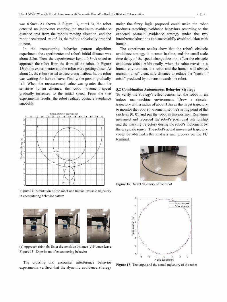
5.2 Combination Autonomous Behavior Strategy
To verify the strategy's effectiveness, set the robot in an indoor man-machine environment. Drew a circular trajectory with a radius of about 3.5m as the target trajectory to monitor the robot's movement, set the starting point of the circle as (0, 0), and put the robot in this position. Real-time measured and recorded the robot's positional relationship and the marking trajectory during the robot's movement by the grayscale sensor. The robot's actual movement trajectory could be obtained after analysis and process on the PC terminal.
Figure 16 Target trajectory of the robot
Figure 17 The target and the actual trajectory of the robot

Qing-Fang Zhang et al.
·12·
In the tracking experiment, the target trajectory and the robot's actual trajectory are shown in Figure 17. The robot can move flexibly. According to the eight light states of the grayscale sensor in each point, calculated the relative position of the corresponding point with the target trajectory, drew the actual trajectory of the robot, recorded the coordinate position of the robot, observed the position error and angle error of the critical point, respectively, as shown in Table 2. Analyzed the robot's motion data and calculated the robot's position error (coordinate unit: meter) and rotation angle error.
Figure 18 Tracking experiment of the robot
In Figure 18, when the robot moved along the target trajectory, it detected that a pedestrian entered the avoidance distance, judged as the encountering pattern, and the robot decelerated on the predetermined trajectory. When the pedestrian gradually moved away from the robot to the avoidance distance, the robot gradually returned to the initial speed and continued to follow the target trajectory movement.
Table 2 Target and actual positions of critical points
critical point
xr/m yr/m x/m y/m position error/m
Angle error/rad
1 0 0 0 0 0 0
2 3.431 3.438 3.434 3.451 0.014 0.007
3 0.004 6.862 0.004 6.861 0.001 0
4 -3.431 3.427 -3.431 3.427 0 0
5 -0.002 0.000 -0.002 0.000 0 0
As shown in Figure 19, adopted the Fuzzy-PID controller, the maximum position error was 0.098m, and at the 18.25th-second, the position error converged to zero. While in the PID controller, the maximum position error was 0.1m, and until the 25.76th second, the position error converged to zero. The robot's maximum angle error was 0.088rad in the Fuzzy-PID controller, and at the 20.05th second, the angle error converged to zero. While in the PID controller, the maximum angle error was 0.175rad, and until the 20.52th second, the
position error converged to zero in Figure 20.
Figure 19 Position error the robot
Figure 20 Angle error of the robot
The experimental results show that the motion controller can help the robot return to the target trajectory more quickly when it deviates from the predetermined position. The robot runs smoothly, and it can complete the inspection of target tracking indoors well, control the position error up to 0.098m and angle error up to 0.088rad. Compared with the PID controller, this paper's Fuzzy-PID controller is more stable, accurate, and fast.
6 Conclusions
This paper designs a mobile robot that can perform
inspection tasks in a narrow human-machine coexistence
environment. Build the robot's kinematic model and
establish a control system's hybrid architecture to develop its
smooth moving ability in narrow space and get overall
coordination and decision-making ability.
(1) In the dynamic narrow time-varying environment,
which shared space between humans and machines, the
team establishes the social force, analyzes human
behavior patterns, and divided into four typical behavior
patterns. It proposes the robot's dynamic obstacle avoidance strategy based on Fuzzy thinking.
(2) The crossing and encountering patterns simulation and
experiment results are similar, which shows that the
fixed-point and fixed-trajectory avoidance methods with
the presented dynamic obstacle avoidance strategy
could help the robot and the human always maintain a
sufficient, safe distance to reduce the "sense of crisis".
Furthermore, the small-scale time delay of the speed

Novel 6-DOF Wearable Exoskeleton Arm with Pneumatic Force-Feedback for Bilateral Teleoperation
·13·
change does not affect the obstacle avoidance effect.
(3) Combine the dynamic obstacle avoidance strategy
presents an autonomous behavior strategy and designs the
Fuzzy-PID controller. The trajectory experiment results
verify that it could help the robot return to the original
trajectory when the robot deviates from the predetermined
trajectory. In an environment where humans and machines
coexist, the robot position error up to 0.098m, the angle error
up to 0.088rad. Besides, the PTZ can rotate 0-360°
horizontally and freely swing -90°-90° vertically. The
robot's inspection is more flexible since the PTZ is
independent of the robot's movement mechanisms, and the
PTZ patrol action group can be set as required. The robot can
transfer back the image information timely and efficiently.
The image transmission speed can reach ten frames per
second.
In summary, the robot designed in this paper can complete the inspection task well in a relatively narrow man-machine environment with the combination autonomous behavior strategy presented in this paper. The application range of hazardous gases inspection robots will be more comprehensive. The robot can reliably implement hazardous gases detection in unattended or dangerous situations, protect humans and robots' safety and better realize human-machine cooperation and coexistence.
7 Declaration
Acknowledgements
The authors sincerely thanks to Xi'an Modern Chemistry
Research Institute for their supports.
Funding
Supported by Research and Development Program of
Xi'an Modern Chemistry Research Institute (Grant No.
204J201916234/6).
Availability of data and materials
The datasets supporting the conclusions of this article are
included within the article.
Authors’ contributions
The author’ contributions are as follows: XG was in charge of the whole trial; QZ wrote the manuscript; XG, BL,
XF and JL assisted with sampling and laboratory analyses.
All authors read and approved the final manuscript.
Competing interests
The authors declare no competing financial interests.
Consent for publication
Not applicable
Ethics approval and consent to participate
Not applicable
References
[1] FG Pratticò, F Lamberti. Mixed-reality robotic games: design guidelines for effective entertainment with consumer robots. IEEE CONSUMER ELECTRONICS MAGAZINE, 2021, 10(1): 6–15.
[2] DY Huang, CG Yang, YP Pan, et al. Composite learning enhanced
neural control for robot manipulator with output error constraints.
IEEE TRANSACTIONS ON INDUSTRIAL INFORMATICS, 2021,
17(1):209–218.
[3] T Yang, XS Gao, FQ Dai. New hybrid AD methodology for minimizing the total amount of information content: a case study of rehabilitation robot design. CHINESE JOURNAL OF MECHANICAL ENGINEERING, 2020, 33(1):1–10.
[4] W Zhang, SL Wei, YB Teng, et al. Dynamic obstacle avoidance for unmanned underwater vehicles based on an improved velocity obstacle method. SENSORS, 2017, 17(12): 2742.
[5] J López , P Sanchez-Vilariño , MD Cacho, et al. Obstacle avoidance in dynamic environments based on velocity space optimization. Robotics and Autonomous Systems, 2020, 131: 103569.
[6] Y Chen, JD Han, HY Wu. Quadratic programming-based approach for autonomous vehicle path planning in space. CHINESE JOURNAL OF MECHANICAL ENGINEERING, 2012, 25(4): 665–673.
[7] T Lv, M Feng. A smooth local path planning algorithm based on modified visibility graph. MODERN PHYSICS LETTERSB, 2017, 31(19–21).
[8] E Ferrera, J Capitan, AR Castano, et al. Decentralized safe conflict resolution for multiple robots in dense scenarios. ROBOTICS AND AUTONOMOUS SYSTEMS, 2017, 91:179–193.
[9] MP Polverini, AM Zanchettin, P Rocco. A computationally efficient safety assessment for collaborative robotics applications. ROBOTICS AND COMPUTER-INTEGRATED MANUFACTURING, 2017, 46: 25–37.
[10] R Singh, TK Bera. Walking model of Jansen Mechanism-based quadruped robot and application to obstacle avoidance. ARABIAN JOURNAL FOR SCIENCE AND ENGINEERING, 2020, 45(2): 653–664.
[11] N Takahashi, N Shibata, K Nonaka. Optimal configuration control of planar leg/wheel mobile robots for flexible obstacle avoidance. CONTROL ENGINEERING PRACTICE, 2020, 101:104503.
[12] Khatib O. Real-time obstacle avoidance for manipu-lators and mobile robots. The International Journal of Robotics Research, 1986, 5(1): 90–98.
[13] CT Diao, SM Jia, GL Zhang, et al. Design and Realization of a Novel Obstacle Avoidance Algorithm for Intelligent Wheelchair Bed Using Ultrasonic Sensors. 2017 CHINESE AUTOMATION CONGRESS (CAC), 2017: 4153–4158.
[14] J. A Janet, R. C Luo, M. G Kay. The Essential Visibility Graph: an approach to global motion planning for autonomous mobile robots. 1995 IEEE International Conference on Robotics and Automation, 1995, 2: 1958–1963.
[15] L Blasi, E D'Amato, M Mattei, et al. Path planning and real-time collision avoidance based on the Essential Visibility Graph. APPLIED

Qing-Fang Zhang et al.
·14·
SCIENCES-BASEL, 2020, 10(16): 5613. [16] l Ulrich, J Borenstein. VFH*: local obstacle avoidance with look-
ahead verification. 2002 IEEE International Conference on Robotics and Automation, 2000:24–28.
[17] XY Li, F Liu, J Liu, et al. Obstacle avoidance for mobile robot based on improved dynamic window approach. TURKISH JOURNAL OF ELECTRICAL ENGINEERING AND COMPUTER SCIENCES, 2017, 25(2): 666–676.
[18] PK Mohanty. An intelligent navigational strategy for mobile robots in uncertain environments using smart cuckoo search algorithm. JOURNAL OF AMBIENT INTELLIGENCE AND HUMANIZED COMPUTING, 2020, 11(12): 6387–6402.
[19] NT Thinh, NT Tuan, LP Huang. Predictive controller for mobile robot based on fuzzy logic. 2016 3RD INTERNATIONAL CONFERENCE ON GREEN TECHNOLOGY AND SUSTAINABLE DEVELOPMENT (GTSD), 2016: 141–144.
[20] YL Fu, SG Wang, ZC Cao. Behavior-based robot fuzzy motion planning approach in unknown environments. CHINESE JOURNAL OF MECHANICAL ENGINEERING, 2006, 42(5): 120–125.
[21] KP Valavanis. The entropy based approach to modeling and evaluating autonomy and intelligence of robotic systems. JOURNAL OF INTELLIGENT & ROBOTIC SYSTEMS, 2018, 91(1): 7–22.
[22] GN Saridis, HE Stephanou. A hierarchical approach to the control of a prosthetic arm. IEEE TRANSACTIONS ON SYSTEMS MAN AND CYBERNETICS, 1977, 7(6): 407–420.
[23] CM Ye, J Li, H Jiang, et al. Semi-Automated Generation of Road Transition Lines Using Mobile Laser Scanning Data. IEEE TRANSACTIONS ON INTELLIGENT TRANSPORTATION SYSTEMS, 2020, 21(5): 1877–1890.
[24] K Ren, Q Wang, C Wang, et al. The security of autonomous driving: threats, defenses, and future directions. PROCEEDINGS OF THE IEEE, 2020, 108(2): 357–372.
[25] XY Li, N Xu, Q Li, et al. A fusion methodology for sideslip angle estimation on the basis of kinematics-based and model-based approaches. PROCEEDINGS OF THE INSTITUTION OF MECHANICAL ENGINEERS PART D-JOURNAL OF AUTOMOBILE ENGINEERING, 2020, 234(7): 1930–1943.
[26] V Dolk, J den Ouden, S Steeghs, et al. Cooperative automated driving for various traffic scenarios: experimental validation in the GCDC 2016. IEEE TRANSACTIONS ON INTELLIGENT TRANSPORTATION SYSTEMS, 2018, 19(4): 1308–1321.
[27] A Hacinecipoglu, EI Konukseven, AB Koku. Multiple human trajectory prediction and cooperative navigation modeling in crowded scenes. INTELLIGENT SERVICE ROBOTICS, 2020, 13(4): 479–493.
[28] E Hall. The Silent Language. Anchor Books Press, 1973: 208-209. [29] SD Lynch, R Kulpa, LA Meerhoff, et al. Influence of path curvature
on collision avoidance behavior between two walkers. EXPERIMENTAL BRAIN RESEARCH, 2020: 1–12.
[30] JD Han, ZQ Zhu, ZY Jiang, et al. Simple PID Parameter Tuning Method Based on Outputs of the Closed Loop System. CHINESE JOURNAL OF MECHANICAL ENGINEERING, 2016, 29(3): 465–474.
Biographical notes
Xue-Shan Gao, born in 1966, is currently a professor at Beijing Institute of Technology, China. His main research interests include mobile robot, intelligent robot and rehabilitation robot. E-mail: [email protected]
Qing-Fang Zhang, born in 1994, is currently a PhD candidate at Beijing Institute of Technology, China. Her research interests include mobile robot, intelligent control and intelligent robotics. E-mail: [email protected]
Bing-Qing Lan, born in 1994, is currently a master candidate at Beijing Institute of Technology, China.
E-mail: [email protected]
Xiao-Long Fu, born in 1982, is currently a researcher at Xi'an Modern Chemistry Research Institute, China. His research interests include unmanned monitoring technology and materials science. E-mail: [email protected]
Jing-Ye Li, born in 1995. He received his master degree from Beijing Institute of Technology, China, in 2020. His research interests include mobile robot technology. E-mail: [email protected]
Appendix No appendix.

Figures
Figure 1
Schematic diagram of the robot overall structure

Figure 2
Kinematics model of the robot

Figure 3
Schematic diagram of the robot turning motion

Figure 4
Social force model

Figure 5
Four types of behavior pattern

Figure 6
Membership function graph of input/output variable
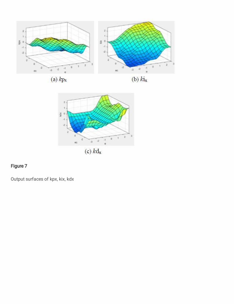
Figure 7
Output surfaces of kpx, kix, kdx

Figure 8
Fuzzy-PID controller of the robot

Figure 9
Motion controller of the robot
Figure 10

Structure of the robot control system
Figure 11
Experiment platform of the robot

Figure 12
Trajectory simulation of robot and human in the crossing behavior pattern

Figure 13
Experiment of crossing behavior
Figure 14
Simulation of the robot and human obstacle trajectory in encountering behavior pattern

Figure 15
Experiment of encountering behavior
Figure 16
Target trajectory of the robot

Figure 17
The target and the actual trajectory of the robot

Figure 18
Tracking experiment of the robot
Figure 19
Position error the robot

Figure 20
Angle error of the robot