a model-based approach for system-level rfic verification
TRANSCRIPT

Approach, Application and Examples
Agilent EEsof EDA
George EstepRF-MS App. Dev. Engr.
July 7, 2011Copyright © 2011 Agilent Technologies

Agenda
The Challenge of RFIC Verification
A New RFIC Verification Flow Based on Behavioral Models
Brief Review of Memory Effects
Historical Survey of Behavioral Verification Models
Application Details Including Important Cautions
System Verification Examples• LTE Uplink Transmitter• Amplifier Digital Predistortion Example
Summary and Conclusion
July 7, 2011Copyright © 2011 Agilent Technologies

The Challenge of RFIC Verification
Two facts combine to ensure that RFIC verification is a very difficult task
• First, modern radios are no longer simple analog circuits
– They are a combination of extremely complex RF and mixed-signal circuitry that interact with each other
• Different design tools are used for different parts of the radio
July 7, 2011
LPFLNA VGA
Rx PLL
LPFPA VGATx
Rx
DIV2
ADC
DAC
Tx PLL
DIV2
Base-Band Proc.
SQUARE
DIGITAL
M/S
ANALOG
Copyright © 2011 Agilent Technologies

The Challenge of RFIC Verification
Two facts combine to ensure that RFIC verification is a very difficult task
• Second, modern radios carry extremely complex signals
July 7, 2011Copyright © 2011 Agilent Technologies

A New RFIC Verification FlowBased on Behavioral Models
July 7, 2011Copyright © 2011 Agilent Technologies
System-level SimulationOn Windows
Circuit DesignOn Linux
Black-boxBehavioral Model

A New RFIC Verification FlowWorkflow
GG: Define File Location, FCE Model Ports, Boundaries and Resolution
GG: Create and Export FCE Model
SV: Instantiate and Parameterize FCE Model and Select Ports
SV: Run FCE Model
• Use GoldenGate on Linux to specify available ports and to define the model boundaries and resolution
• Run GoldenGate to create Fast Circuit Envelope (FCE) “Black Box” model
• Use SystemVue on Windows to place and parameterize models and select ports
• Run system-level simulations on SystemVue
July 7, 2011Copyright © 2011 Agilent Technologies
Linux Windows

A New RFIC Verification FlowKey Features
On the model-creation side:
• Model creation is performed on Linux in the native design environment.
• Model creation is performed by the circuit simulation expert.
• Very large circuits can be modeled.• “Black-box” FCE model can include
both nonlinear and memory effects, if required.
• Frequency translation is supported.• All details of the model are contained
within a single model file.• Model creation time is independent of
model simulation speed.
On the model-usage side:
• Model usage is performed by the system simulation expert.
• Extremely fast simulation using an advanced data-flow engine– Allows mixing of many different
domains in a single simulation• Access to extensive standards-
compliant wireless libraries• Multiple FCE models can be used
simultaneously.• Windows platform allows inclusion of
instruments in verification simulations.• Simulator errors/warns if model is
operated outside of calibrated range.
July 7, 2011Copyright © 2011 Agilent Technologies

A New RFIC Verification FlowThe Model is One Key to this Flow
July 7, 2011Copyright © 2011 Agilent Technologies
System-level SimulationOn Windows
Circuit DesignOn Linux
Black-boxBehavioral Model
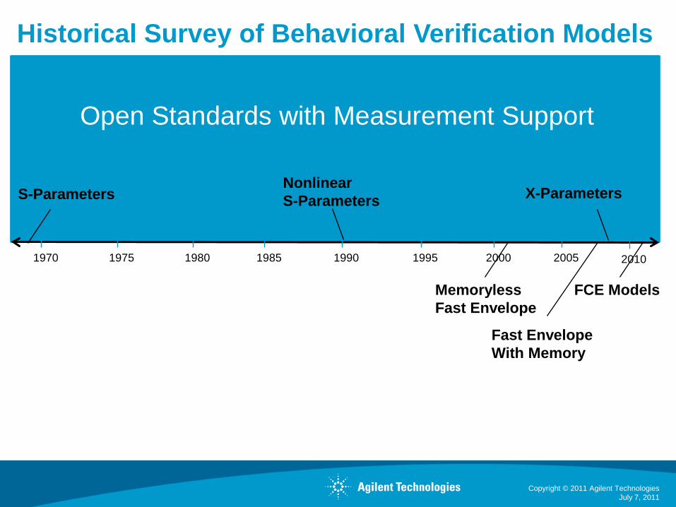
Historical Survey of Behavioral Verification Models
July 7, 2011Copyright © 2011 Agilent Technologies
1970 1975 1980 1985 1990 1995 2000 2005
S-Parameters
2010
NonlinearS-Parameters X-Parameters
MemorylessFast Envelope
Fast EnvelopeWith Memory
FCE Models
Open Standards with Measurement Support

Brief Review of Memory Effects
Memory effects are non-noise circuit characteristics which cannot be described by the steady-state nonlinear transfer function of the circuit.• Filtering effects• Delay effects• Hysteretic effects
Memory effects make it difficult to predict circuit response to modulated waveforms based upon steady-state characteristics.We will group memory effects by time-constant magnitude:• “Baseband” memory effects tend to have long time constants• “Inband” memory effects tend to have short time constants
July 7, 2011
Vout
Vin
Copyright © 2011 Agilent Technologies

July 7, 2011
Manifestations of Memory Effects in CircuitsSome examples
• Multiple time-constant memory effects
Thermal effects Trapping effects
Biasing circuits AGC loops
DC offset correction
Matching networks(group delay)
Band filtering
Transistors (transit time)
Long time-constantmemory
~µs to ms
Short time-constantmemory
~ns
BasebandMemory Effects
InbandMemory Effects
Nonlinear Coupling
Copyright © 2011 Agilent Technologies

July 7, 2011
Manifestations of Memory Effects in CircuitsHow can you detect them with a steady-state solver?
• You typically need to sweep frequency to see these effects.• Here are examples of what you might see for an amplifier:
10
11
12
13
14
15
16
17
18
-10 -8 -6 -4 -2 0 2 4
()
1.86GHz1.90GHZ1.95GHZ1.99GHZ2.03GHZ
wrapping
Input power (dBm)
Gai
n (d
B)
Some inband effects can be seen by sweeping a single tone in a steady-state simulation
Some baseband effects can be seen by sweeping the difference between two tones in a steady-state simulation
10
15
20
25
30
35
40
45
50
0 1 2 3 4 5 6 7 8 9 10
pp
p
()
Pin=-10dBm
Pin=-2dBm
Pin=-6dBm
Pin=2dBm
Lower IM3 Upper IM3
Tone spacing (MHz)
C/IM
3 ra
tio (d
B)
resonance
Copyright © 2011 Agilent Technologies

Simulation Techniques for Modulated Waveforms Two Main Types of Envelope Behavioral Models
Memoryless model:
• Use a steady-state solver to calculate AM-AM and AM-PM characteristics for the circuit for the fundamental and harmonics at the center of the band and at various power levels.
• Interpolate within this result to estimate the response of the circuit to a time-varying stimulus.
Model with memory effects:
• Modeling memory effects requires more and different types of characterization of the circuit than creating a memoryless model.
• Inband and baseband effects are handled differently due to the fact that they are quite different phenomena.
July 7, 2011
Vout
Vin
Baseband memory model
Inband memory model
OutputInput
Copyright © 2011 Agilent Technologies

Circuit Simulation ExamplesPower Amplifier – Output Spectrum Comparison
July 7, 2011
RED – Normal Envelop Transient GREEN – Memoryless Model BLUE – Model with Memory
Copyright © 2011 Agilent Technologies

Circuit Simulation ExamplesPower Amplifier – Performance Comparison
Method Used Accurate? ModelTime
Sim Time SimSpeedup
Envelope Transient 0 sec 1133 sec 1XEnvelope w/ Memoryless Model <1 sec 7 sec 162XEnvelope w/ Memory Model 40 sec 101 sec 11X
July 7, 2011
• For a memoryless circuit, ALL envelope transient approaches covered give the same correct results.– It is important to verify that the circuit is memoryless by verifying the
results against normal envelope simulation.• In this case, the memoryless model is the most efficient since it requires
the fewest simulations to complete.
Copyright © 2011 Agilent Technologies
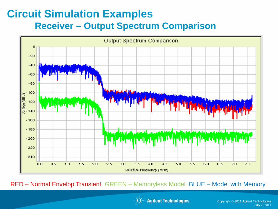
Circuit Simulation ExamplesReceiver – Output Spectrum Comparison
July 7, 2011
RED – Normal Envelop Transient GREEN – Memoryless Model BLUE – Model with Memory
Copyright © 2011 Agilent Technologies

Circuit Simulation ExamplesReceiver – Performance Comparison
Method Used Accurate? ModelTime
Sim Time SimSpeedup
Envelope Transient 0 sec 1560 sec 1XEnvelope w/ Memoryless Model X 58 sec 14 sec 111XEnvelope w/ Memory Model 17985 sec 37 sec 42X
July 7, 2011
• For circuits with memory, a memoryless model can give very poor results.– It is important to verify that the results from the model with memory using
normal envelope simulation.• In this case, the behavioral model with memory is accurate but it is slower
than regular envelope transient simulation. In many cases, it will be faster. Many factors will impact the speed.
Copyright © 2011 Agilent Technologies

SIMULATION GENERAL’S WARNING:THE SIMULATION GENERAL OF EESOF HAS DETERMINED THAT THE IMPROPER USE OF BEHAVIORAL MODELS FOR VERIFICATION PURPOSES CAN BE HAZARDOUS TO THE HEALTH OF YOUR CIRCUITS. PLEASE CAREFULLY FOLLOW ALL GUIDELINES FOR PROPER GENERATION, DOCUMENTATION AND APPLICATION OF YOUR BEHAVIORAL MODELS. FAILURE TO DO SO IS KNOWN TO THE STATE OF CALIFORNIA TO RESULT IN MISSED SPECIFICATIONS, MALFUNCTION OR POSSIBLY EVEN DEATH OF YOUR CIRCUITS.
July 7, 2011Copyright © 2011 Agilent Technologies
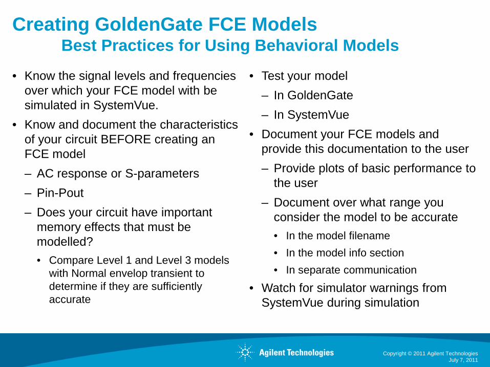
Creating GoldenGate FCE ModelsBest Practices for Using Behavioral Models
• Know the signal levels and frequencies over which your FCE model with be simulated in SystemVue.
• Know and document the characteristics of your circuit BEFORE creating an FCE model– AC response or S-parameters– Pin-Pout– Does your circuit have important
memory effects that must be modelled?• Compare Level 1 and Level 3 models
with Normal envelop transient to determine if they are sufficiently accurate
• Test your model– In GoldenGate– In SystemVue
• Document your FCE models and provide this documentation to the user– Provide plots of basic performance to
the user– Document over what range you
consider the model to be accurate• In the model filename• In the model info section• In separate communication
• Watch for simulator warnings from SystemVue during simulation
July 7, 2011Copyright © 2011 Agilent Technologies

Creating GoldenGate FCE ModelsLimits on memoryless model bandwidth
July 7, 2011Copyright © 2011 Agilent Technologies
Memoryless ModelBandwidth Limit

Creating GoldenGate FCE ModelsCarefully select the input amplitude range
July 7, 2011Copyright © 2011 Agilent Technologies
Choose a range of input amplitudes whichwill meet the needs of the system verification efforts.
SystemVuehard-clips here!

FCE Model Usage in SystemVue
Polymorphic behavior on the system side allows switching between:
– Various FCE models• Different corners• Different circuit settings• Different designs
– Cosimulation with full circuit– Top-down behavioral model– Other simulation views, if available
FCE models run natively in SystemVue in seconds
Copyright © 2011 Agilent Technologies
July 7, 2011

Fast Circuit Envelope (FCE) Verification ModelingModel used in SystemVue in an LTE Uplink test
Copyright © 2011 Agilent TechnologiesJuly 7, 2011
Coded LTE UL Source RFIC CMOS PA “FastCircuitEnvelope” modelExported from GoldenGate
89600 VSA LTE demod

Fast, Reliable System-Level Performance in seconds.
Copyright © 2011 Agilent TechnologiesJuly 7, 2011
Pout = +19.3dBm, ACLR=23dBcCPU time = 3 sec (150k points)
Pout = +10.6dBm, ACLR=37dBcCPU time = 3 sec (150k points)
Nominal PA LTE result Compressing PA LTE result
1200X Speedup!!
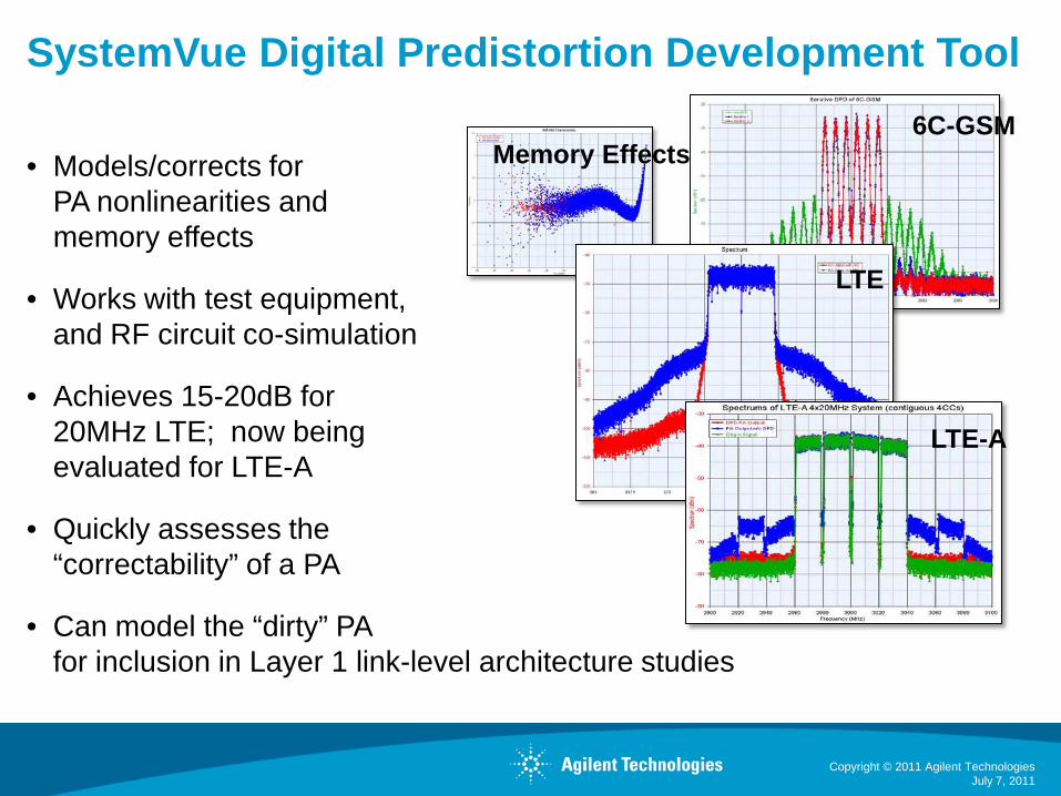
SystemVue Digital Predistortion Development Tool
• Models/corrects for PA nonlinearities and memory effects
• Works with test equipment,and RF circuit co-simulation
• Achieves 15-20dB for 20MHz LTE; now being evaluated for LTE-A
• Quickly assesses the “correctability” of a PA
• Can model the “dirty” PAfor inclusion in Layer 1 link-level architecture studies
July 7, 2011Copyright © 2011 Agilent Technologies
6C-GSM
LTE
LTE-A
Memory Effects

Amplifer Digital PredistortionSimulation Closely Duplicates Measurement
July 7, 2011Copyright © 2011 Agilent Technologies
External Trigger
Attenuator N5182 MXG
or E8257D PSGas external modulatorM9330A AWG if > 100 MHz
89600VSA
M9392A PXI VSA (>140MHz)or N9030A PXA (<140 MHz)
I,Q RF
RF DUT
SIMULATION-BASED DPD(predictive)
• ADS & GoldenGate Circuits as simulated RF DUTs- Complex loading, memory FX, dynamic behaviors
• NVNA X-parameter measurement model,- Great for smaller solid-state devices
X-parameters
RF DUTN5241,2 PNA-X
MEASUREMENT-BASED DPD
CO-SIM, MODELS
CO-SIM, MODELS
MODEL
ADS
GG

Summary and Conclusion
A new approach for verifying system-level behavior of a modern RFIC has been presented.• Fast, accurate data-flow models of RFIC blocks or systems can now be created from
circuit simulation.– Full memory effects can be included if required.
• A survey of historical behavioral modeling approaches shows that we are finally converging on models that capture BOTH nonlinear behavior AND memory effects.
• Caution is given about the proper application of these new techniques.• Example simulations demonstrate the power of performing extremely fast verification of
circuitry within a full-featured system-level tool.– Access to instruments within the system-level environment is a big benefit of
operating in a Windows-based environment.
Conclusion: More comprehensive system-level verification is now a reality for a wide range of RFIC applications.
July 7, 2011Copyright © 2011 Agilent Technologies

Questions and Answers
Thank You!
July 7, 2011Copyright © 2011 Agilent Technologies

July 7, 2011
http://www.agilent.com/find/eesof-goldengatehttp://www.agilent.com/find/eesof-systemvue
Where do you go from here?
• Visit GoldenGate and SystemVue on the web to sign up for a demonstration or evaluation.
• Download the GoldenGate Workshop and go through the examples used in this webcast.
• Contact your local Agilent EEsof field representative or
George Estep, RF-MS Application [email protected]
Frank Ditore, SystemVue Marketing Manager [email protected]
Attend other RFIC Webcasts from Agilent EEsof EDA:• Memory Effects in RF Circuits: Manifestations and Simulation • LTE-Advanced: Overcome Design Challenges for 4G PHY Architectures
Copyright © 2011 Agilent Technologies