a model for analyzing aircraft maintenance man-hour costs
TRANSCRIPT

Calhoun: The NPS Institutional Archive
Theses and Dissertations Thesis Collection
1995-06
A model for analyzing aircraft maintenance
man-hour costs and the impact of expert systems
Schanz, Keith E.
Monterey, California. Naval Postgraduate School
http://hdl.handle.net/10945/31486

NAVAL POSTGRADUATE SCHOOL MONTEREY, CALIFORNIA
19960220 054 THESIS
A MODEL FOR ANALYZING AIRCRAFT MAINTENANCE MAN-HOUR COSTS AND
THE IMPACT OF EXPERT SYSTEMS
by
Keith E. Schanz
and
Donnie L. Shirkey
June 1995
Principal Advisor: Martin J. McCaffrey
Approved for public release; distribution is unlimited.
s Qp&Lssrs mEmmmj-&
REPORT DOCUMENTATION PAGE Form Approved OMB No. 0704-0188
Public gathering a collection c D°a"X"hX"^^
1. AGENCY USE ONLY (Leave blank) 2. REPORT DATE
June 1995 3. REPORT TYPE AND DATES COVERED
Master's Thesis 4. TITLE AND SUBTITLE
A MODEL FOR ANALYZING AIRCRAFT MAINTENANCE MAN-HOUR COSTS AND THE IMPACT OF EXPERT SYSTEMS
6. AUTHOR(S) Schanz, Keith E. Shirkey, Donnie L.
7. PERFORMING ORGANIZATION NAME(S) AND ADDRESS(ES)
Naval Postgraduate School Monterey, CA 93943-5000
9. SPONSORING /MONITORING AGENCY NAME(S) AND ADDRESS(ES)
5. FUNDING NUMBERS
8. PERFORMING ORGANIZATION REPORT NUMBER
10. SPONSORING /MONITORING AGENCY REPORT NUMBER
11. SUPPLEMENTARY NOTES
The views expressed in this thesis are those of the author and do not reflect the official policy or position of the Department of Defense or the U.S. Government. ^^
12a. DISTRIBUTION/AVAILABILITY STATEMENT
Approved for public release; distribution is unlimited.
12b. DISTRIBUTION CODE
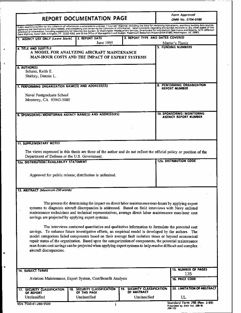
13. ABSTRACT (Maximum 200 words)
The process for determining the impact on direct labor maintenance man-hours by applying expert systems to diagnosis aircraft discrepancies is addressed. Based on field interviews with Navy enlisted maintenance technicians and technical representatives, average direct labor maintenance man-hour cost savings are projected by applying expert systems.
The interviews contained quantitative and qualitative information to formulate the potential cost savings. To enhance future investigative efforts, an empirical model is developed by the authors. The model categorizes failed components based on their average fault isolation times or beyond economical repair status of the organization. Based upon the categorization of components, the potential maintenance man-hours cost savings can be projected when applying expert systems to help resolve difficult and complex aircraft discrepancies.
14. SUBJECT TERMS
Aviation Maintenance, Expert System, Cost/Benefit Analysis
17. SECURITY CLASSIFICATION OF REPORT Unclassified
18. SECURITY CLASSIFICATION OF THIS PAGE
Unclassified
19. SECURITY CLASSIFICATION OF ABSTRACT
Unclassified
15. NUMBER OF PAGES 135
16. PRICE CODE
20. LIMITATION OF ABSTRACT
UL
NSN 7540-01-280-5500 Standard Form 298 (Rev. 2-89) Prescribed by ANSI Std. 239-18 298-102

UNCLASSIFIED
SECURITY CLASSIFICATION OF THIS PAGE
#13 ABSTRACT (CONTINUED)
The F/A-18C, E-2C and S-3B aircraft top five component maintenance man-hour consumers at the organizational and intermediate maintenance levels are also reviewed in detail for fiscal year 1994. The thesis concludes with a discussion on the potential benefits of expert systems for aircraft maintenance diagnostics and recommendations for further study.
SECURITY CLASSIFICATION OF THIS PAGE
UNCLASSIFIED

Approved for public release; distribution is unlimited.
A MODEL FOR ANALYZING AIRCRAFT MAINTENANCE
MAN-HOUR COSTS AND THE IMPACT OF EXPERT SYSTEMS
Keith E. Schanz
Lieutenant Commander, United States Navy
B.S., Humboldt State University, 1980
Donnie L. Shirkey
Lieutenant, United States Navy B.S., Embry-Riddle Aeronautical University, 1983
Submitted in partial fulfillment of the requirements for the degree of
MASTER OF SCIENCE IN MANAGEMENT
from the
Author:
Approved by:
NAVAL POSTGRADUATE SCHOOL June 1995/
Martin J. McCaffrey, Princ: isor
ters, Associate Advisor
David R. Whipple, Chairman
Department of Systems Management
m

IV
ABSTRACT
The process for determining the impact on direct labor maintenance man-hours by
applying expert systems to diagnosis aircraft discrepancies is addressed. Based on field
interviews with Navy enlisted maintenance technicians and technical representatives,
average direct labor maintenance man-hour cost savings are projected by applying expert
systems.
The interviews contained quantitative and qualitative information to formulate the
potential cost savings. To enhance future investigative efforts, an empirical model is
developed by the authors. The model categorizes failed components based on then-
average fault isolation times or beyond economical repair status of the organization.
Based upon the categorization of components, the potential maintenance man-hours cost
savings can be projected when applying expert systems to help resolve difficult and
complex aircraft discrepancies.
The F/A-18C, E-2C and S-3B aircraft top five component maintenance man-hour
consumers at the organizational and intermediate maintenance levels are also reviewed in
detail for Fiscal Year 1994. The thesis concludes with a discussion on the potential
benefits of expert systems for aircraft maintenance diagnostics and recommendations for
further study.

VI

TABLE OF CONTENTS
I. INTRODUCTION 1
A. OBJECTIVES 1
B. SCOPE, LIMITATIONS AND ASSUMPTIONS 2
C. RESEARCH METHODOLOGY 2
D. THESIS ORGANIZATION 3
II. OVERVIEW OF NAVAL AVIATION MAINTENANCE 5
A. ORGANIZATIONAL LEVEL (O-LEVEL) MAINTEN- ANCE 5
B. INTERMEDIATE LEVEL (I-LEVEL) MAINTENANCE ... 6
C. DEPOT LEVEL (D-LEVEL) MAINTENANCE 7
D. MAINTENANCE DATA SYSTEM 8
E. NAVAL AVIATION MAINTENANCE TERMS 9
1. System 9
2. Subsystem 10
3. Component 10
4. Weapons Replaceable Assembly (WRA) 10
5. Shop Replaceable Assembly (SRA) 10
6. Work Unit Code (WUC) 10
7. Malfunction Description Code 11
vn

8. Maintenance Man-Hours (MMHs) 11
9. Elapsed Maintenance Time (EMT) 11
10. Not Mission Capable (NMC) 11
11. Not Mission Capable Maintenance (NMCM) 11
12. Not Mission Capable Supply (NMCS) 12
13. A-799 12
14. Maintenance Instruction Manual (MIM) 12
F. ENGINEERING AND TECHNICAL SERVICES, NAVY (NETS) AND CONTRACTOR (CETS) 12
G. SUMMARY 13
III. F/A-18C, E-2C AND S-3B DIRECT LABOR MAINTENANCE MAN-HOUR COSTS 15
A. MMH COST PER HOUR 15
B. F/A-18C HORNET 17
1. Top Five F/A-18C Component MMH Consumers at the O-Level 18
2. Top Five F/A-18C Component MMH Consumers at the I-Level 18
3. F/A-18C MMH Costs 21
C. E-2C HAWKEYE 21
1. Top Five E-2C Component MMH Consumers at the O-Level 23
2. Top Five E-2C Component MMH Consumers at the I-Level 23
3. E-2C MMH Costs 23
viii
D. S-3B VIKING 27
1. Top Five S-3B Component MMH Consumers at the O-Level 27
2. Top Five S-3B Component MMH Consumers at the I-Level 29
3. S-3B MMH Costs 29
E. SUMMARY 31
IV. EXPERT SYSTEMS OVERVIEW 33
1. Components of an Expert System 34
2. Developing an Expert System 34
A. USERS OF EXPERT SYSTEMS 35
1. McDonnell Douglas Corporation 35
2. Center for Artificial Intelligence Applications (CAIA) 36
3. United States Air Force (USAF) 36
B. BENEFITS OF USING EXPERT SYSTEMS 37
1. Dupont 37
2. Toyota Motor Company 37
C. SUMMARY 38
V. MAINTENANCE MAN-HOUR COST SAVINGS USING EXPERT SYSTEMS 39
A. KEY TERMS AND RATES USED TO CALCULATE MMH COST SAVINGS 40
IX

1. MMHs 40
2. Fault Isolation Percentage 40
3. Pertinency Rate 40
4. Efficiency Rate 41
B. OVERVIEW ON CALCULATING AVERAGE MMH COST SAVINGS 42
C. F/A-18C HORNET AVERAGE MMH COST SAVINGS 42
1. O-Level Cost Savings 43
2. I-Level Cost Savings 43
D. E-2C HAWKEYE AVERAGE MMH COST SAVINGS 44
1. O-Level Cost Savings 44
2. I-Level Cost Savings 47
E. S-3B VIKING AVERAGE MMH COST SAVINGS 48
1. O-Level Cost Savings 48
2. I-Level Cost Savings 51
F. THE SHIRKEY-SCHANZ EXPERT SYSTEM MAINTEN- ANCE MAN-HOUR COST SAVINGS MODEL 53
G. SUMMARY 64
VI. RESEARCH QUESTIONS AND ANSWERS/CONCLUSIONS/ LESSONS LEARNED/ RECOMMENDATIONS 67
A. RESEARCH QUESTIONS AND ANSWERS 68
B. CONCLUSIONS 73
x

C. LESSONS LEARNED 73
1. NALDA 74
2. Logistics Management Decision Support System (LMDSS) 75
3. Electro-Optical Test Set (EOTS) 75
4. VAST/CASS 76
5. A-799 76
6. NETS/CETS 77
D. RECOMMENDATIONS 78
LIST OF REFERENCES 109
BIBLIOGRAPHY Ill
INITIAL DISTRIBUTION LIST 113
XI

Xll
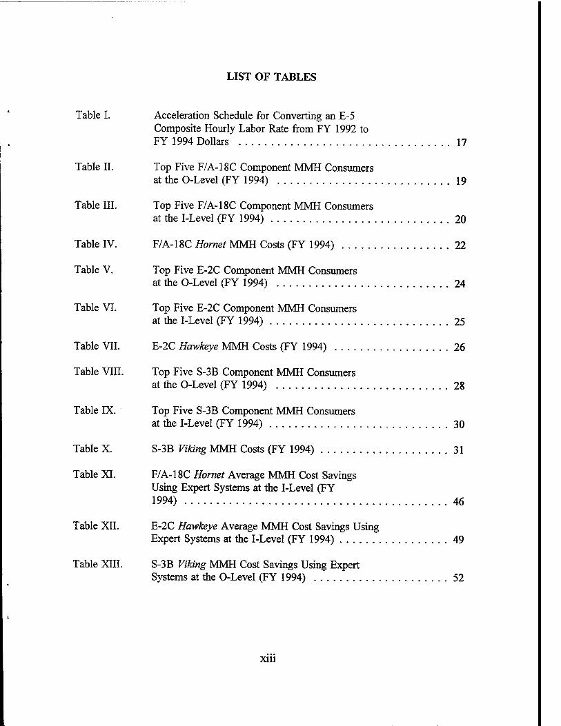
LIST OF TABLES
Table I. Acceleration Schedule for Converting an E-5 Composite Hourly Labor Rate from FY 1992 to FY 1994 Dollars 17
Table II. Top Five F/A-18C Component MMH Consumers at the O-Level (FY 1994) 19
Table III. Top Five F/A-18C Component MMH Consumers at the I-Level (FY 1994) 20
Table IV. F/A-18C Hornet MMH Costs (FY 1994) 22
Table V. Top Five E-2C Component MMH Consumers at the O-Level (FY 1994) 24
Table VI. Top Five E-2C Component MMH Consumers at the I-Level (FY 1994) 25
Table VII. E-2C Hawkeye MMH Costs (FY 1994) 26
Table VIII. Top Five S-3B Component MMH Consumers at the O-Level (FY 1994) 28
Table IX. Top Five S-3B Component MMH Consumers at the I-Level (FY 1994) 30
Table X. S-3B Viking MMH Costs (FY 1994) 31
Table XI. F/A-18C Hornet Average MMH Cost Savings Using Expert Systems at the I-Level (FY 1994) 46
Table XII. E-2C Hawkeye Average MMH Cost Savings Using Expert Systems at the I-Level (FY 1994) 49
Table XIII. S-3B Viking MMH Cost Savings Using Expert Systems at the O-Level (FY 1994) 52
Xlll

Table XIV. S-3B Viking Average MMH Cost Savings Using Expert Systems at the I-Level (FY 1994) 54
Table XV. Expert System Impact on S-3B MMHs and MMH Cost Savings 63
xiv

LIST OF ABBREVIATIONS AND ACRONYMS
AEW
AE1
AIMD
ASW
ATI
AT2
AW
AZ1
BCM
CAIA
CASS
CETS
CND
CONUS
DD
D-LEVEL
DOD
DPRO
DSF
EMT
ENSAC
Airborne Early Warning
Aviation Electrician's Mate First Class
Aircraft Intermediate Maintenance Department
Anti-Submarine Warfare
Aviation Electronics Technician First Class
Aviation Electronics Technician Second Class
Aviation Warfare
Aviation Maintenance Administrationman First Class
Beyond the Capability of Maintenance
Center for Artificial Intelligence Applications
Consolidated Automated Support System
Contractor Engineering and Technical Services
Cannot Duplicate
Continental United States
Defense Department
Depot Level
Department Of Defense
Defense Plant Representative Office
Data Services Facility
Elapsed Maintenance Time
ENgine Structural Analysis Consultant
xv

EOTS
ETS
FCMDS
FCS
FFG
FLIR
FY
HR
HRS
IBM
ICS
IEEE
I-LEVEL
LCDR
LT
MAD
MAF
MDS
METER
MM
ML1
ML2
Electro-Optical Test Set
Engineering and Technical Services
Flight Control Maintenance Diagnostic System
Fire Control System
Guided Missile Frigate
Forward-Looking Infrared Radar
Fiscal Year
Hour
Hours
International Business Machines
Intercommunication Systems
Institute of Electrical and Electronic Engineers
Intermediate Level
Lieutenant Commander
Lieutenant
Magnetic Anomaly Detection
Maintenance Action Form
Maintenance Data System
Metrology Equipment Recall Card
Maintenance Instruction Manual
Maintenance Level 1
Maintenance Level 2
xvi
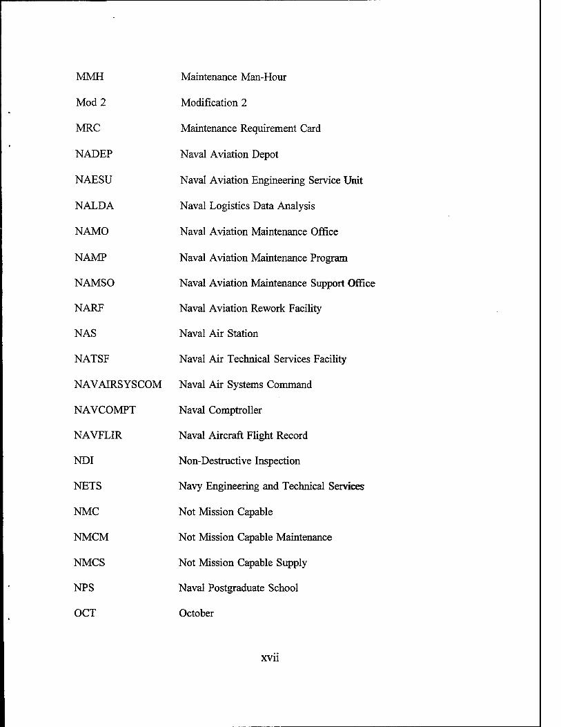
MMH Maintenance Man-Hour
Mod 2 Modification 2
MRC Maintenance Requirement Card
NADEP Naval Aviation Depot
NAESU Naval Aviation Engineering Service Unit
NALDA Naval Logistics Data Analysis
NAMO Naval Aviation Maintenance Office
NAMP Naval Aviation Maintenance Program
NAMSO Naval Aviation Maintenance Support Offi
NARF Naval Aviation Rework Facility
NAS Naval Air Station
NATSF Naval Air Technical Services Facility
NAVAIRSYSCOM Naval Air Systems Command
NAVCOMPT Naval Comptroller
NAVFLIR Naval Aircraft Flight Record
NDI Non-Destructive Inspection
NETS Navy Engineering and Technical Services
NMC Not Mission Capable
NMCM Not Mission Capable Maintenance
NMCS Not Mission Capable Supply
NPS Naval Postgraduate School
OCT October
XVII
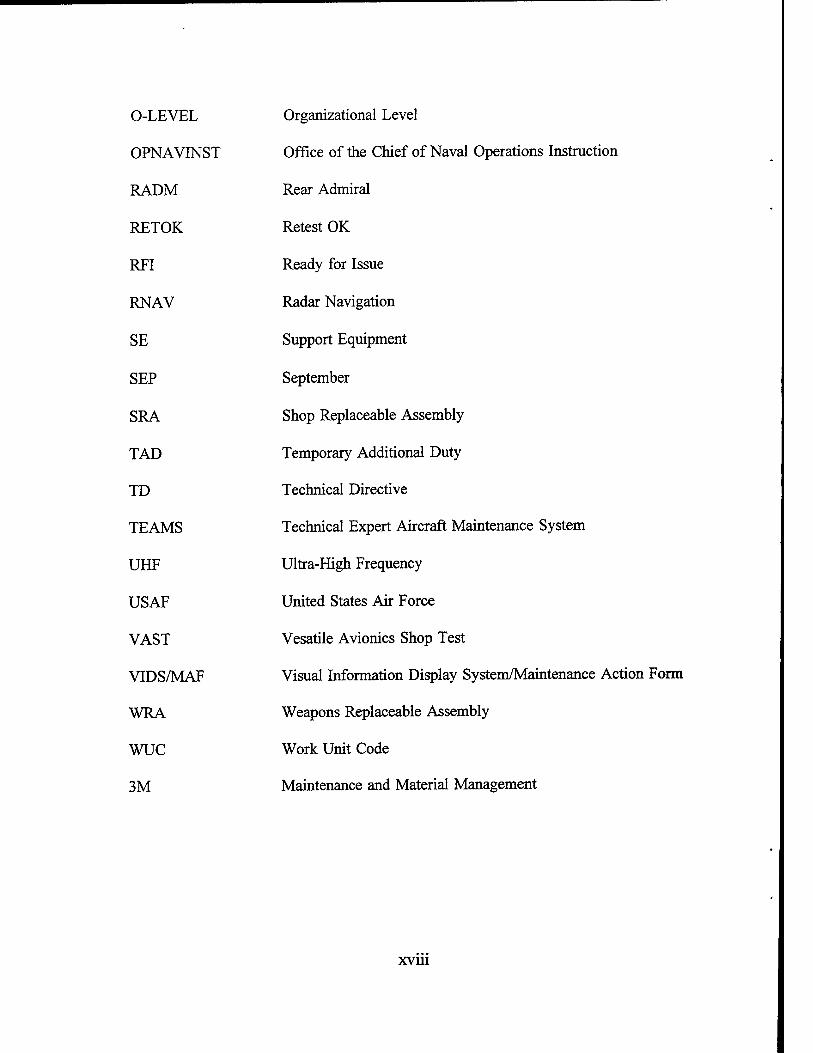
O-LEVEL
OPNAVINST
RADM
RETOK
RFI
RNAV
SE
SEP
SRA
TAD
TD
TEAMS
UHF
USAF
VAST
VIDS/MAF
WRA
WUC
3M
Organizational Level
Office of the Chief of Naval Operations Instruction
Rear Admiral
Retest OK
Ready for Issue
Radar Navigation
Support Equipment
September
Shop Replaceable Assembly
Temporary Additional Duty
Technical Directive
Technical Expert Aircraft Maintenance System
Ultra-High Frequency
United States Air Force
Vesatile Avionics Shop Test
Visual Information Display System/Maintenance Action Form
Weapons Replaceable Assembly
Work Unit Code
Maintenance and Material Management
xvin

ACKNOWLEDGEMENTS
The following people contributed significant amounts of their personal and
professional time to assist the authors with data collection and provided valuable inputs.
Their dedication and assistance were indispensable to the successful completion of this
thesis.
Special thanks go to the people at the Aircraft Intermediate Maintenance
Department (AIMD) at Naval Air Station (NAS) Lemoore, California. LCDR Marty
Jones (Assistant Aircraft Maintenance Officer) provided unlimited access to essential
resources, but in particular, AZl(AW)Gilman of the quality assurance/analysis division,
provided accurate data on numerous, short noticed occasions. AEl(AW) Reynolds of the
quality assurance/analysis division also provided valuable expertise and liaisoned with
organizational and intermediate F/A-18 Hornet maintenance technicians.
CW04 Sid Adams, Officer-in-Charge of the Naval Aviation Engineering Services
Unit (NAESU) Detachment Lemoore, Mr. Benny Warren and Mr. John Forte (NAESU
Detachment Lemoore technical representatives) provided essential information on NAESU
operations and introduced/educated the authors on the Electro-Optical Test Set (EOTS)
system.
ATI (AW) Fowler of AIMD quality assurance/analysis division at NAS Miramar,
California, lent his time to provide the E-2C Hawkeye maintenance related information.
AD1 Stein from the same activity provided the Hawkeye's propeller/power plant systems
information.
xix

AEl(AW) Carson of VS-33 quality assurance/analysis division provided the
expertise for the S-3B Viking organizational level maintenance data. Much appreciation
is also due to Mr. Jim Vizzard of Lockheed Corporation for his valuable inputs with
respect to Viking components and the AIMD versatile avionics shop test (VAST) bench
at NAS North Island, California.
Special thanks to Donald F. Eaton RADM (Ret) of the Naval Postgraduate School
for his valuable insight and review of this thesis.
xx

I. INTRODUCTION
Naval aviation maintenance managers in the post-cold war period are responsible
for ensuring aircraft maintenance continues to be performed in a safe, efficient manner.
This proves to be a continual challenge considering declining Department of Defense
(DOD) resources, the decommissioning of aircraft squadrons and a general reduction in
forces.
Maintenance managers must continually seek new ways to optimize scarce
resources and assist technicians in maintaining aircraft systems at the organizational,
intermediate and depot maintenance levels.
Research at the Naval Postgraduate School (NPS) demonstrated that using expert
system software to troubleshoot the primary fire control system of guided missile frigates
(FFGs) offered significant savings in support parts and marked improvement in
operational readiness.1
The commercial and defense aerospace field has also developed expert systems
(Prerau, 1990). This thesis looks at one factor for evaluating the employment of expert
systems for meeting future challenges in the field of Naval aviation maintenance.
A. OBJECTIVES
The primary objective of this research is to determine a process for determining
the impact on direct labor maintenance man-hours (MMHs) of applying expert systems
to assist in diagnosis of aircraft discrepancies.
The secondary objective of this research is to identify direct labor MMH costs
associated with the Hornet, Hawkeye and Viking aircraft at the organizational and
intermediate maintenance levels.
'A developmental expert system, designated as the MK 92 Modification 2 (Mod 2) Fire Control System (FCS) Maintenance Advisor Expert System, is used to troubleshoot the fire control system of the U.S. Navy's Oliver Hazard Perry class of FFGs. (Powell, 1993)

The following primary research question is addressed:
• Can a model be developed to derive the potential direct labor MMH cost savings by using expert systems to assist fault isolation of Hornet, Hawkeye and Viking systems/components?
Secondary research questions include:
• What are some of the potential benefits of using expert systems in the Naval aviation maintenance field?
• What are the top five component MMH consumers at the organizational maintenance level for the Hornet, Hawkeye and Viking aircraft during Fiscal Year 1994?
• What are the top five component MMH consumers at the intermediate maintenance level for the Hornet, Hawkeye and Viking aircraft during Fiscal Year 1994?
• What are the direct labor MMH costs, using conventional fault isolation methods to identify failed components, for the three aircraft during Fiscal Year 1994?
B. SCOPE, LIMITATIONS AND ASSUMPTIONS
This study is limited to potential economic consideration of the use of expert
systems to reduce direct labor MMHs required to fault isolate Hornet, Hawkeye and
Viking components. Because of the long lead time requirements to obtain usable data, the
study does not address the economic feasibility of potentially using expert systems to
resolve aircraft readiness degraders or A-799 (no defect, malfunction could not be
duplicated, item checks good) issues. Study assumptions are stated within the context that
they occur.
C. RESEARCH METHODOLOGY
Data collection for this thesis was conducted on-site and through telephone
conversations. Organizations and personnel that supported this research included: the

Naval Aviation Maintenance Office (NAMO, Code 352-1); the Aircraft Intermediate
Maintenance Department (AIMD), Naval Air Station (NAS) Lemoore, California; the
Naval Aviation Engineering Service Unit (NAESU) Detachment Lemoore, NAS Lemoore,
California; Antisubmarine Squadron 33 (VS-33); AIMD NAS North Island, California;
AIMD NAS Miramar, California; McDonnell Douglas Corporation, Saint Louis, Missouri;
and a group of Aerospace Maintenance Duty Officers assigned to the NPS, Monterey,
California.
Description of Naval aviation maintenance programs, procedures and terms are
based on applicable aviation maintenance instructions and the authors' knowledge and
experience gained while collectively serving at four separate Naval aircraft squadrons and
two AIMDs.
An in-depth review of commercial and military aviation maintenance literature was
conducted. In addition an independent self study was performed by the authors to gain
a working knowledge about expert systems.
D. THESIS ORGANIZATION
The remaining chapters of this thesis are organized as follows:
II. OVERVIEW OF NAVAL AVIATION MAINTENANCE. The Naval Aviation
Maintenance Program and its controlling document, Office of the Chief of Naval
Operations Instruction (OPNAVINST 4790.2E, Volumes I-VI), are briefly discussed. An
overview of organizational, intermediate and depot maintenance levels is presented and
their specific functions are outlined. Also, the Maintenance Data System (MDS) is
reviewed, specific Naval aviation maintenance terms are explained and Navy/contractor
engineering and technical services are discussed.
III. F/A-l 8C. E-2C AND S-3B DIRECT LABOR MAINTENANCE MAN-HOUR
COSTS. For each of the identified aircraft, the top five component MMH consumers at
the organizational and intermediate maintenance levels are listed. The common causes
of failure, MMHs expended using conventional fault isolation methods and a direct labor

MMH cost associated with the failed components are identified. The chapter data is for
the time frame October 1993 to September 1994.
IV. EXPERT SYSTEMS OVERVIEW. An overview of expert systems is given
that includes how expert systems differ from conventional computer programs, the two
main system components and their related functions, and the basic steps of how to
develop such systems. Commercial and military applications of expert systems are
discussed. Included are three specific aviation maintenance uses and the benefits realized
from this advanced technology.
V. MAINTENANCE MAN-HOUR COST SAVINGS USING EXPERT
SYSTEMS. The concept of using expert systems to help fault isolate F/A-18C, E-2C and
S-3B weapon systems is introduced. Based on interviews with Navy enlisted maintenance
technicians and technical representatives, average direct labor MMH cost savings are
projected from using expert systems. In order to better quantify potential direct labor
MMH cost savings benefits from the application of expert systems, an empirical model
is developed by the authors.
VI. RESEARCH QUESTIONS AND ANSWERS/CONCLUSIONS/LESSONS
LEARNED/RECOMMENDATIONS. A summary of research findings and recommenda-
tions are provided. This includes lessons learned and other potential areas to investigate
expert systems usage in the field of Naval aviation maintenance.

II. OVERVIEW OF NAVAL AVIATION MAINTENANCE
The purpose of this section is to inform readers not aware of the Naval aviation
maintenance process of applicable terms used throughout this study. The high tempo and
operational demands of Naval aviation require scheduled and unscheduled aircraft
maintenance critical to safe and successful operations. The training and expertise of the
technicians and controllers charged with maintaining the aircraft systems is a significant
factor in the success or failure of the organization.
The guiding document for Naval Aviation Maintenance is the Office of the Chief
of Naval Operations Instruction (OPNAVINST) 4790.2 Series, known as the Naval
Aviation Maintenance Program (NAMP). The NAMP presents maintenance policies,
procedures and responsibilities for all levels of maintenance throughout Naval aviation.
It is the basic document and authority governing management of all Naval aviation
maintenance. (OPNAVINST 4790.2E, Volume I)
The NAMP consists of six interrelated volumes. Volume I is primarily
introductory, providing concepts, organizational layout, guidance for using the NAMP,
Marine Corps maintenance organization, contract maintenance, definitions and change
submission procedures. Volume II deals with organizational level maintenance, Volume
III with intermediate level maintenance and Volume IV with depot level maintenance.
Volume V is concerned with the maintenance data systems, and Volume VI with
maintenance data processing requirements. Each of these maintenance levels and
categories is explained in the following sections.
A. ORGANIZATIONAL LEVEL (O-LEVEL) MAINTENANCE
Organizational level maintenance is most commonly associated with squadron
maintenance. These organizations are the custodians and users of the actual weapons
system (i.e., aircraft). Functions and assignment of responsibilities are specifically
delineated for all areas of the maintenance activity. Maintenance at the O-level consists
primarily of rapid fault isolation and removal/replacement of weapons system components

at the operational site. Routine scheduled maintenance and inspections (including
painting, corrosion control/treatment and aircraft launch/recovery) are part of O-level
maintenance. The NAMP states:
When removal and replacement of components from a weapons system is required, using only O-level test equipment and hand tools, the maintenance function is O-level. (OPNAVINST 4790.2E, Volume II)
Limited overlap between O-level and intermediate maintenance (I-level) functions
are allowed only with justification. It warrants specific approval from the Naval Air
Systems Command (NAVAIRSYSCOM).
O-level is considered the most basic level of maintenance logistically, requiring
the "least-skilled personnel" (Blanchard, 1992). In practice, squadron level maintenance
involves rapid diagnosis and high tempo, dynamic responses to aircraft discrepancies.
At the O-level, tools and test equipment are largely portable. They are designed
for deployments and detachments, which are the normal course of operations for an
organizational maintenance activity. Organizational maintenance requirements are
designed to facilitate the dynamic requirements of fault isolation and repair of components
to enhance readiness and mobility.
B. INTERMEDIATE LEVEL (I-LEVEL) MAINTENANCE
Faulty components that have been removed from the aircraft by the O-level
maintenance activity are normally beyond the repair capability of that activity. In such
cases, a squadron receives a Ready For Issue (RFI) component for reinstallation from the
supporting supply department. The faulty component is turned-in/forwarded to the AIMD
for repair.
AIMDs are the primary source for mamtaining the required level of organizational
activity repairable spare parts inventory for the supply department. They are autonomous,
independent repair facilities charged with the long-term sustainability of deployed forces.
They may be either situated ashore (shore based) or afloat (seagoing). A typical AIMD

provides repair facilities for several squadrons and a wide variety of aircraft (fixed wing,
rotary wing, jets, propellers).
Shore based AIMDs normally provide repair capability for all the types of aircraft
where the AIMD is located. As with O-level repair, some overlap with O-level or depot
level (D-level) maintenance is allowed as long as justification and specific approval is
received from NAVAIRSYSCOM.
The repair facilities at I-level are much more in-depth than those at the O-level.
Specialized repair and test bench equipment are available for avionics, electrical,
hydraulics, environmental/egress, power plants and support equipment systems. Test
equipment calibration labs and Non-Destructive Inspection (NDI) equipment is also
available. In addition airframe welding, composite and conventional airframe repair,
plating, painting and corrosion control/treatment capabilities are available.
Repairs are accomplished by technicians specifically trained in I-level repair
techniques. As a result of the scope and depth of repairs undertaken, AIMDs are
normally much larger organizations than their O-level squadron counterparts. Their role
is continually expanding due to their necessary independence resulting from the
geographic and technological scope of operations they support.
C. DEPOT LEVEL (D-LEVEL) MAINTENANCE
The final level of aircraft maintenance is at the depot level. D-level maintenance
functions include three general categories: rework, manufacture and support services. In
addition, depots perform special structural inspections and in-service engineering
functions.
Rework is comprised of maintenance and modification. It includes restoration,
rebuilding, reclamation, refurbishment, overhaul, repair, replacement, adjustment,
servicing, inspection, calibration and testing. Changes and improvements to design
through alterations, conversions, engineering changes and modernizations are also
performed. (OPNAVINST 4790.2E, Volume IV)

Manufacture involves the manufacture of items and component parts otherwise not
available. Support service functions include professional engineering, technology and
calibration services. (OPNAVINST 4790.2E, Volume IV)
The structure and composition of the depot level work force is dramatically
different than either the organizational or intermediate level. The technicians are almost
exclusively civilian, with very few military members involved. Military officers primarily
serve in executive and administrative roles. The recent downsizing in defense has seen
a reduction in the number of depots.
Naval Aviation Depots are officially known as "NADEPs." NADEPs have the
capability to perform rework or complete overhaul on aircraft to extend the aircraft's
active service life. The maintenance tasks at NADEPs are much more in-depth and time
consuming than either organizational or intermediate maintenance activities. Depot level
maintenance often requires the actual transfer of aircraft custody, both physically and
administratively, from an operational organization to a depot activity.
D. MAINTENANCE DATA SYSTEM
The Maintenance Data System (MDS) is part of the Navy's Maintenance and
Material Management (3M) System and provides the data input to the NAMP. MDS
furnishes statistical data products which serve as management tools for efficient and
economical maintenance management. MDS deals with equipment maintainability and
reliability, equipment configuration (including alteration and technical directive (TD)
status), equipment mission capability and utilization, material usage, material non-
availability, maintenance/ material processing times and weapon systems/maintenance
material costing. (OPNAVINST 4790.2E, Volume V)
MDS requires command attention, support and use since MDS products are only
as good as the input information. The system is designed so mat each worker, when
performing a job, converts a narrative description of the job into codes. The information
is entered on standard forms or source documents. (OPNAVINST 4790.2E, Volume V)
Source documents are collected and transmitted to a data services facility (DSF)
and converted to machine records which produce periodic reports. These reports provide
assistance in planning and directing maintenance. The machine records are then
forwarded to the Naval Aviation Maintenance Support Office (NAMSO). (OPNAVINST
4790.2E, Volume V)
A number of senior maintenance executives, the authors and many technicians feel
the information available from MDS is not perfect and has inherent limitations.
Demanding flight schedules and the paperwork burdens of MDS do not mix well with
tired maintenance personnel and flight deck operations. The primary goals of
maintenance personnel are related to aircraft readiness, sortie completion, and safety; not
with detailed data collection.
Data for this thesis was obtained from the Naval Logistics Data Analysis
(NALDA) facility in Patuxent River, Maryland. NALDA is a management information
system for aviation logistics management and technical decision support. Analysis
capability is provided through interactive query and batch processing from remote
terminals. (OPNAVINST 4790.2E, Volume V) NPS is not a remote terminal site.
E. NAVAL AVIATION MAINTENANCE TERMS
Since the following terms are used throughout this thesis, they are explained to
acquaint readers with language used in the Naval aviation maintenance field and to
facilitate the understanding of this study.
1. System
A system includes related facilities, items, material, services and personnel such
that it can be considered a self-sufficient item in its intended operation. (OPNAVINST
4790.2E, Volume V) Examples of a complete system are an aircraft landing gear system,
integrated flight control system or radar navigation system.

2. Subsystem
A combination of two or more pieces of equipment, generally separated in
operation and such other parts necessary to perform an operational function or functions.
(OPNAVINST 4790.2E, Volume V) Examples include a port main landing gear
(subsystem) of an aircraft landing gear system or a rudder control system (subsystem) of
an integrated flight control system.
3. Component
A number of parts joined together to perform a specific function. This applies to
items that cannot be further disassembled for test or repair without requiring shop
facilities. (OPNAVINST 4790.2E, Volume V) Examples include a mainmount or an
actuator.
4. Weapons Replaceable Assembly (WRA)
A generic term which includes all replaceable packages of avionic equipment, pods
or systems in an aircraft weapons system, with the exception of cables, mounts, fuse
boxes, or circuit breakers. A WRA is composed of shop replaceable assemblies (SRAs).
(OPNAVINST 4790.2E, Volume V)
5. Shop Replaceable Assembly (SRA)
A generic term which includes all the packages within a WRA, including the
chassis and wiring for a unit. SRA is a term usually associated with intermediate level
maintenance. (OPNAVINST 4790.2E, Volume V)
6. Work Unit Code (WUC)
The WUC is a one, three, five, or seven character numeric or alpha/numeric code.
It identifies a system, subsystem, or part of an end item. These codes are published in
WUC manuals for end items in three major categories: (1) Type/Model/Series for aircraft,
drones and missiles; (2) aircraft tactical trainers, and (3) aeronautical support equipment
(SE). The WUC manuals are used to code maintenance actions on end items and
components. The system code consists of the first two positions of the WUC and
identifies the system within the aircraft/equipment. (OPNAVINST 4790.2E, Volume V)
10

7. Malfunction Description Code
A three-character numeric or alphanumeric code used to describe the malfunction
occurring on or in an item identified by a WUC. (OPNAVINST 4790.2E, Volume V)
8. Maintenance Man-Hours (MMHs)
Maintenance man-hours are the total accumulated direct labor hours expended in
performing a maintenance action. Direct maintenance man-hours are man-hours expended
by assigned personnel to complete work. This includes the functions of preparation,
inspection, disassembly, fault isolation, adjustment, replacement or reassembly of parts
and calibration/tests required in restoring the item to a serviceable status.
MMHs also include checking out and returning tools, looking up part numbers in
illustrated parts breakdown manuals, transmitting required information to supply points
and completing associated documentation. (OPNAVINST 4790.2E, Volume V)
9. Elapsed Maintenance Time (EMT)
EMT is defined as the actual clock time that maintenance was being performed on
a job. EMT does not include cure time, charging time, or leak tests when conducted
without maintenance personnel actually monitoring the work. Although EMT is directly
related to job man-hours, it is not to be confused with total man-hours required to
complete a job. For example, if five men complete a job in 2.0 hours of continuous
work, the EMT = 2.0 hours and total man-hours = 10.0. (OPNAVINST 4790.2E, Volume
V)
10. Not Mission Capable (NMC)
The material condition of an aircraft or training device, indicating that it is not
capable of performing any of its missions. It is further subdivided as the sum of Not
Mission Capable Maintenance (NMCM) and Not Mission Capable Supply (NMCS).
(OPNAVINST 4790.2E, Volume V)
11. Not Mission Capable Maintenance (NMCM)
The material condition of an aircraft or training device, indicating that it is not
capable of performing any of its missions because of O-level or I-level maintenance
requirements. (OPNAVINST 4790.2E, Volume V)
11
12. Not Mission Capable Supply (NMCS)
The material condition of an aircraft or training device, indicating that it is not
capable of performing any of its missions because the maintenance required to fix or clear
the discrepancy cannot continue due to a supply shortage. (OPNAVINST 4790.2E,
Volume V)
13. A-799
In order to determine the causes of aircraft discrepancies, rapid diagnostics must
be performed at the organizational level, often in the hectic environment of aircraft carrier
flight deck operations. This frequently requires the removal of an aircraft component
which is sent to the afloat AIMD for repair.
In the event that AIMD is unable to find fault with the component, it is returned
to Ready for Issue (RFI) status after a thorough test and check. When such a component
is returned with no defect found, the item is considered A-799.
14. Maintenance Instruction Manual (MIM)
A manual containing instructions for organizational and intermediate maintenance
and servicing of a specific model aircraft. It identifies each maintenance task to the
responsible maintenance level.
F. ENGINEERING AND TECHNICAL SERVICES, NAVY (NETS) AND CONTRACTOR (CETS)
NETS and CETS support services are composed of technical experts specializing
in various aircraft weapons systems and test/repair facilities. Contractors supply employee
CETS personnel (McDonnell Douglas, Grumman, Lockheed). NETS personnel are
controlled by the Naval Aviation Engineering Service Unit (NAESU).
NAESU is a field activity of NAVAIRSYSCOM and reports directly to the
Assistant Commander for Logistics and Fleet Support. NAESU head-quarters is located
at the Naval Base in Philadelphia, Pennsylvania.
12

NAESU's mission is to provide field engineering technical assistance and
instruction to Naval aviation activities in the installation, maintenance repair and operation
of aviation systems and equipment. (NAESU 50th Anniversary Brochure)
G. SUMMARY
This chapter provided an overview of the Naval aviation maintenance program.
The topics covered were a breakdown of the Naval aviation maintenance organization,
general/specific responsibilities, and the inter-relationships between respective
organizational areas. Selected terms were defined that are used throughout the body of
this research. Chapter III provides a snapshot view of the direct labor MMH costs,
without using expert systems, to fault isolate aircraft systems or components.
13

14

III. F/A-18C, E-2C AND S-3B DIRECT LABOR MAINTENANCE MAN-HOUR COSTS
Maintenance managers have gauges to measure the efficiency, effectiveness and
economic performance levels of an organization. Direct labor maintenance man-hours
(MMHs) is one gauge used in the aviation maintenance field to measure performance
levels. When managers know the number of MMHs consumed, plus the rates of labor to
perform specific maintenance actions, the organization's direct labor cost can be
determined.
This chapter briefly describes the F/A-18C Hornet, E-2C Hawkeye and S-3B
Viking aircraft and their roles. For each of the aircraft, the top five component
maintenance man-hour (MMH) consumers at the organizational and intermediate
maintenance levels are presented and evaluated. A direct labor MMH cost per hour is
calculated and combined with the selected weapon system's MMHs. This information
gives a snapshot view of how much it directly costs to support the aircraft maintenance
effort.
The direct labor MMH costs are based solely on using conventional fault isolation
methods.2 No use of an expert system is considered. All direct labor MMH costs will
be referred to as MMH costs throughout the remainder of this study. Also, all MMH
costs were incurred from October 1993 to September 1994. Therefore, the costs are
presented in Fiscal Year (FY) 1994 dollars.
A. MMH COST PER HOUR
On the basis of the authors' 32 years of accumulated experience in aviation
maintenance, a decision was made to use the E-5 paygrade to calculate an hourly labor
cost to perform aircraft maintenance. This decision was based on the following:
Conventional fault isolation methods consist of technicians using maintenance instruction manuals (MIMs), experience, suggestions of counterparts, and any available resource materials and/or assistance from technical representatives to solve aircraft maintenance problems.
15

• E-7 and above personnel perform aviation maintenance manager related functions and do not perform "hands-on" maintenance tasks unless absolutely necessary.
• E-6 personnel supervise the vital functions of their work centers and maintain constant communications with maintenance control at the organizational maintenance level and production control at the intermediate maintenance level.
• E-5 personnel perform the vast majority of fault isolation and repair/replace maintenance actions. They are technically competent, have completed their training tracks and are not required to perform temporary additional duty (TAD) functions.
• E-4 and below personnel do not perform the majority of fault isolation and repair/replace maintenance actions. Their weapon system's learning curve rate is high as compared to other technicians. Also, they have not completed their training tracks and are eligible to perform TAD functions.
• Maintenance requirement cards (MRCs) delineate specific maintenance tasks for each rating/paygrade. E-5 is an acceptable average.
The composite hourly labor rate for an E-5 maintenance technician is $16.28, in
FY 1992 dollars, as provided in Naval Comptroller (NAVCOMPT) Notice 7041 dated
1992. The composite rate does not factor in compensation for leave and holiday accrual,
medical benefits and accrual of other personnel support costs.
An hourly labor rate of $16.28 must be accelerated by: (1) a factor of 114 percent
to compensate for leave and holiday accrual, and (2) a factor of 118 percent to
compensate for accrual of other personnel support costs (NAVCOMPT Notice 7041, p.
5-95). The composite hourly labor rate is therefore $21.90 for an E-5 maintenance
technician in FY 1992 dollars.
Since this study uses FY 1994 weapons system's data, the FY 1992 $21.90 rate
is inflated by a factor of 105.89 percent. This establishes an E-5 composite hourly labor
rate of $23.19 in FY 1994 dollars (Office of Management and Budget, 1994). The E-5
composite hourly rate of $23.19 is used to in calculate MMH costs and average MMH
cost savings. Table I summarizes this process. Following the table, a discussion of each
aircraft and breakout of the top component MMH consumers is made.
16

$16.28 Composite hourly labor rate for an E-5 in FY 1992 dollars
x 114% Accelerated compensation factor for leave and holiday accrual
$18.56 Composite hourly labor rate for an E-5, in FY 1992 dollars, after applying the leave and holiday acceleration factor
x 118% Accelerated composition factor for accrual of other personnel support costs
$21.90 Composite hourly labor rate for an E-5, in FY 1992 dollars, after applying the accrual of other personnel support costs acceleration factor
x 105.89% Inflation factor to convert FY 1992 dollars to FY 1994 dollars
$23.19 E-5 composite hourly labor rate in FY 1994 dollars
Table I. Acceleration Schedule for Converting an E-5 Composite Hourly Labor Rate from FY 1992 to FY 1994 Dollars
B. F/A-18C HORNET
The F/A-18C Hornet is a dual engine, single-seat aircraft that performs the strike-
fighter role in the Navy and Marine Corps. The Hornet is highly maneuverable, is
capable of Mach plus speed and armed with a 20-millimeter cannon. Wingtip positions,
three fuselage stations and four wing stations for weapons and sensor/guidance pods,
enable the aircraft to perform its role merely by changing weapon racks. (Polmar, 1987)
As of September 30, 1994, there were 333 F/A-18C aircraft in the Navy/Marine Corps
inventory.
Three questions are often asked by aviation maintenance managers: (1) which
components fail, (2) what causes the components to fail, and (3) what are the number of
MMHs consumed in fault isolation and repair/ replacement of failed components.
Once these questions are asked, aviation maintenance managers are better able to
analyze aircraft maintenance problems and provide viable solutions to problems.
17

Based on the previous three questions, a short discussion on the top five O- and
I-level component MMH consumers, the causes of failure, and the associated costs for the
three aircraft follows.
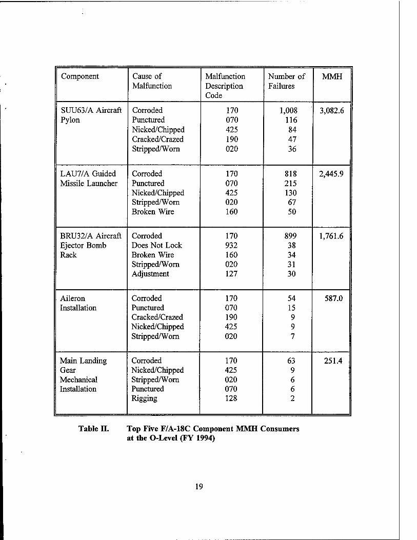
1. Top Five F/A-18C Component MMH Consumers at the O-Level
Table II lists the top five component MMH consumers for the period October 1993
to September 1994. The number one Hornet MMH consumer was the SUU63/A aircraft
pylon. Corrosion was the leading cause of failure; 3,082.6 MMHs were consumed fixing
pylon failures. The second largest MMH consumer was the LAU7/A guided missile
launcher. The leading cause of failure, once again, was corrosion; 2,445.9 MMHs were
consumed by launcher failures.
The BRU32/A aircraft ejector rack was the third leading consumer of MMHs.
Corrosion was again the leading cause of failure; 1,761.6 MMHs were consumed by
ejector rack failures. Aileron installation was the fourth leading MMH consumer at the
O-level. The number one cause of failure was corrosion. Aileron failures accounted for
587.0 MMHs.
The main landing gear mechanical installation completed the list of top five
component MMH consumers. Corrosion was the main cause of failure; 251.5 MMHs were
consumed. Additional weapon systems data can be found in Appendix A.
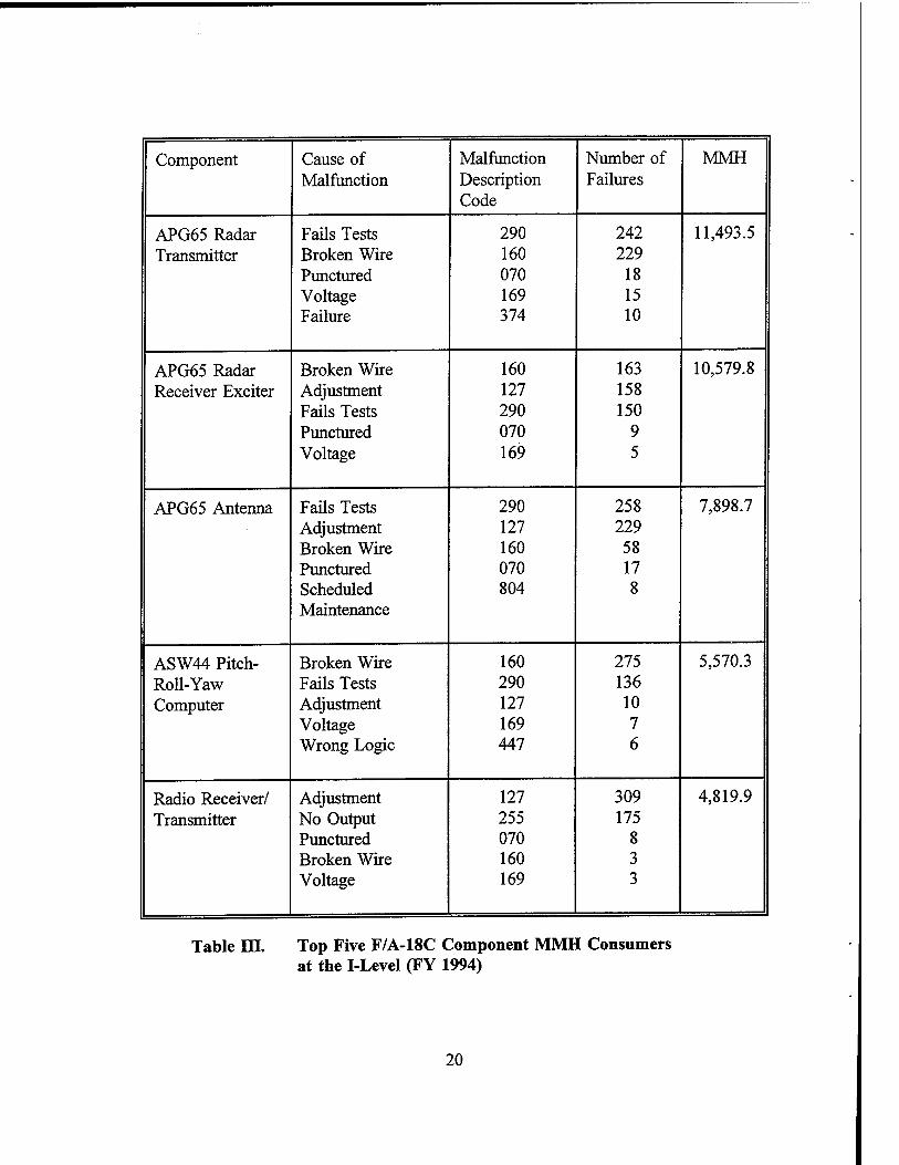
2. Top Five F/A-18C Component MMH Consumers at the I-Level
As listed in Table III, the APG652 radar transmitter, APG65 radar receiver exciter
and APG65 antenna consumed the majority of MMHs. These three components are
subsystem components of the weapons control system. They are identified by a WUC 74
two-digit system code.
2Weapon systems are categorized by equipment indicator letters. These letters indicate where the equipment is installed, what type of equipment it is and what function(s) the equipment performs. For example, the APG code is broken down as follows: A indicates equipment installed and operated in aircraft, P indicates radar equipment and G indicates fire control or search directing equipment.
18
Component Cause of Malfunction Number of MMH Malfunction Description
Code Failures
SUU63/A Aircraft Corroded 170 1,008 3,082.6 Pylon Punctured 070 116
Nicked/Chipped 425 84 Cracked/Crazed 190 47 Stripped/Worn 020 36
LAU7/A Guided Corroded 170 818 2,445.9 Missile Launcher Punctured 070 215
Nicked/Chipped 425 130 Stripped/Worn 020 67 Broken Wire 160 50
BRU32/A Aircraft Corroded 170 899 1,761.6 Ejector Bomb Does Not Lock 932 38 Rack Broken Wire 160 34
Stripped/Worn 020 31 Adjustment 127 30
Aileron Corroded 170 54 587.0 Installation Punctured 070 15
Cracked/Crazed 190 9 Nicked/Chipped 425 9 Stripped/Worn 020 7
Main Landing Corroded 170 63 251.4 Gear Nicked/Chipped 425 9 Mechanical Stripped/Worn 020 6 Installation Punctured 070 6
Rigging 128 2
Table II. Top Five F/A-18C Component MMH Consumers at the O-Level (FY 1994)
19
Component Cause of Malfunction Number of MMH Malfunction Description
Code Failures
APG65 Radar Fails Tests 290 242 11,493.5 Transmitter Broken Wire 160 229
Punctured 070 18 Voltage 169 15 Failure 374 10
APG65 Radar Broken Wire 160 163 10,579.8 Receiver Exciter Adjustment 127 158
Fails Tests 290 150 Punctured 070 9 Voltage 169 5
APG65 Antenna Fails Tests 290 258 7,898.7 Adjustment 127 229 Broken Wire 160 58 Punctured 070 17 Scheduled 804 8 Maintenance
ASW44 Pitch- Broken Wire 160 275 5,570.3 Roll-Yaw Fails Tests 290 136 Computer Adjustment 127 10
Voltage 169 7 Wrong Logic 447 6
Radio Receiver/ Adjustment 127 309 4,819.9 Transmitter No Output 255 175
Punctured 070 8 Broken Wire 160 3 Voltage 169 3
Table III. Top Five F/A-18C Component MMH Consumers at the I-Level (FY 1994)
20

Since the components are part of a common system, their data was aggregated
together. Fails diagnostic/automatic tests and broken wire/defective contact/connection
were the leading causes of failure. The APG65 components accounted for 29,972.0
MMHs.
The ASW44 pitch-roll-yaw computer was the fourth leading consumer of MMHs.
The leading cause of failure was broken wire/defective contact/connection. This type of
failure occurred 275 times. The second leading cause of failure was fails
diagnostic/automatic tests. It occurred 136 times and MMHs consumed by the ASW44
came to 5,570.3.
The radio receiver/transmitter (WUC 62X21) concluded the list of top five
component MMH consumers. The leading cause of failure was adjustment/alignment
improper; 4,819.9 MMHs were consumed during FY 1994.
3. F/A-18C MMH Costs
Table IV lists the costs for the O-level and I-Ievel top five component MMH
consumers. The total cost for the top five MMH consumers was $1,124,499.33 for
Hornet maintenance at both levels.
The Hornet MMH cost drivers occurred at the intermediate maintenance level. The
weapons control system components (WUCs 742G1, 742G2, 742G6) accounted for
approximately 62 percent of the total MMH cost When one factors in the ASW44 pitch-
roll-yaw computer and radio receiver/ transmitter failures, the I-level accounted for 83
percent total MMH costs in the F/A-18C.
C. E-2C HAWKEYE
The E-2C Hawkeye is a carrier-based Airborne Early Warning (AEW) aircraft
developed specifically for aircraft carrier operations. The Hawkeye's most distinctive
feature is a 24-foot diameter, saucer-like radome that houses the ultra high frequency
(UHF) radar. The radar gives the aircraft an effective detection range of approximately
240 nautical miles. It has both over land and water capability. More than 250 air targets
21

Component WUC MMH MMH Cost Per Hour
MMH Costs
O-Level
SUU63/A Aircraft Pylon
75E51 3,082.6 $23.19 $71,485.49
LAU7/A Guided Missile Launcher
751B6 2,445.9 $23.19 $56,720.42
BRU32/A Aircraft Ejector Bomb Rack
754CD 1,761.6 $23.19 $40,851.50
Aileron Installation
14211 587.0 $23.19 $13,612.53
Main Landing Gear Mechanical Installation
13C11 251.4 $23.19 $5,829.97
I-Level
APG65 Radar Transmitter
742G1 11,493.5 $23.19 $266,534.27
APG65 Radar Receiver Exciter
742G2 10,579.8 $23.19 $245,345.56
APG65 Antenna 742G6 7,898.7 $23.19 $183,170.85
ASW44 Pitch- Roll-Yaw Computer
57D91 5,570.3 $23.19 $129,175.26
Radio Receiver/ Transmitter
62X21 4,819.9 $23.19 $111,773.48
Total MMH Cost $1,124,499.33
Table IV. F/A-18C Hornet MMH Costs (FY 1994)
can be simultaneously tracked and up to 30 interceptors can be controlled. (Polmar,
1987) As of September 30, 1994, there were 123 E-2C aircraft in the Navy inventory.
22

1. Top Five E-2C Component MMH Consumers at the O-Level
Table V lists the top five component MMH consumers for the period October 1993
to September 1994. The number one Hawkeye component MMH consumer was the
variable pitch propeller. Corrosion was the primary cause of failure; this was followed
closely by internal/external leaking. Propeller failures accounted for 4,808.3 MMHs.
The second leading MMH consumer was the power plant system installation/engine
assembly. Corrosion was once again the leading cause of failure. Related failures
accounted for 2,716.0 MMHs.
Utility lights consumed the third largest amount of MMHs. Burned out light
bulbs/fuses was the leading cause of failure. Utility light failures accounted for 1,639.1
MMHs. The rudder was the fourth leading consumer of MMHs at the O-level. Corrosion
was the primary cause of failure. Rudder failures consumed 1,298.7 MMHs.
The O-level's fifth largest MMH consumer was the propeller control assembly.
Corrosion, again, was the leading cause of failure. The propeller control assembly
consumed 510.7 MMHs.
2. Top Five E-2C Component MMH Consumers at the I-Level
The radar navigation (RNAV) system (WUC 72) had four of the top five
component MMH consumers. The components (WUCs 726J2, 726J4, 728E2, 728E1) are
part of a common system and the data is therefore aggregated. Table VI and Appendix
A have more detailed data. Broken wire/defective contact/connector, adjustment/
alignment improper and "no output" were the leading causes of failure. The RNAV
system accounted for 7,383.3 MMHs. The AIC14 intercommunication system (ICS)
control was the remaining top five MMH consumer. All five leading causes of failure
were closely distributed. The AIC14 accounted for 2,491.9 MMHs.
3. E-2C MMH Costs
The Hawkeye's total MMH cost was $483,465.12 for the top five selected weapon
systems data. Organizational level MMH cost accounted for approximately 53 percent of
the total cost. As documented in Table VII, the variable pitch propeller (WUC 32512)
was the major O-level cost driver. It accounted for 23 percent of the total MMH cost
23

Component Cause of Malfunction Number of MMH Malfunction Description
Code Failures
Variable Pitch Corroded 170 67 4,808.3 Propeller Stripped/Worn 020 62
Deteriorated 117 44 Adjustment 127 44 Out of Balance 458 40
Power Plant Corroded 170 241 2,716.0 System Install/ Adjustment 127 70 Engine Contamination 306 70 Assembly Stripped/Worn 020 68
Leaking 381 36
Utility Light Burned Out Bulbs/Fuses
080 1,060 1,639.1
Broken Wire 160 100 Punctured 070 76 Corroded 170 31 Internal Failure 374 13
Rudder Corroded 170 95 1,298.7 Stripped/Worn 020 40 Cracked 190 32 Nicked 425 32 Punctured 070 19
Propeller Corroded 170 14 510.7 Control Leaking 381 8 Assembly Punctured 070 5
Fluctuates 037 4 Adjustment 127 3
Table V. Top Five E-2C Component MMH Consumers at the O-Level (FY 1994)
24

Component Cause of Malfunction Malfunction Description Code
Number of Failures
MMH
Azimuth Range Adjustment 127 102 7,160.5 Indicator Broken Wire
Fails Tests Punctured Internal Failure
160 290 070 374
85 75 15 4
AIC14 ICS No Output 255 77 2,491.9 Control Punctured
Broken Wire Adjustment Internal Failure
070 160 127 374
63 57 31 10
Azimuth Range Punctured 070 15 202.2 Indicator Broken Wire
Adjustment Stuck/Binding Fails Tests
160 127 135 290
12 7 2 2
Digital Data Punctured 070 7 17.0 Converter Broken Wire
Internal Failure 160 374
1 1
Digital Data Adjustment 127 1 3.6 Computer
Table VI. Top Five E-2C Component MMH Con! miners at the I-Level (FY 1994)
25

Component WUC MMH MMH Cost Per Hour
MMH Costs
O-Level
Variable Pitch Propeller
32512 4,808.3 $23.19 $111,504.48
Power Plant System Installation/ Engine Assembly
29E10 2,716.0 $23.19 $62,984.04
Utility Light 4422K 1,639.1 $23.19 $38,010.73
Rudder 14121 1,298.7 $23.19 $30,116.85
Propeller Control Assembly
32513 510.7 $23.19 $11,843.13
I-Level -
Azimuth Range Indicator
726J2 7,160.5 $23.19 $166,052.00
AIC14 ICS Control 64184 2,491.9 $23.19 $57,787.16
Azimuth Range Indicator
726J4 202.2 $23.19 $4,689.02
Digital Data Converter
728E2 17.0 $23.19 $394.23
Digital Data Computer
728E1 3.6 $23.19 $83.48
Total MMH Cost $483,465.12
Table VII. E-2C Hawkeye MMH Costs (FY 1994)
26

Forty-seven percent of the total MMH cost was accumulated at the intermediate
maintenance level. The azimuth range indicator (WUC 726J2) was the number one cost
driver, accounting for 34 percent of the total cost. The combined I-level cost driver data
for WUCs 726J2, 726J4, 728E2 and 728E1 accounted for only 35 percent of the total
MMH cost.
D. S-3B VIKING
The S-3B Viking is a Navy, aircraft carrier deployable, anti-submarine warfare
(ASW) aircraft. It has an internal weapons bay and carries an assortment of weapons,
including torpedoes. It has two wing pylons capable of carrying Harpoon anti-ship
missiles, a variety of bombs, aerial refueling stores that provide an in-flight refueling
capability, and general material transport via a blivet. The aircraft's ASW systems
include magnetic anomaly detection (MAD), forward-looking infrared radar (FLIR), and
sonobuoys in fuselage chutes. (Polmar, 1987) As of September 30, 1994, there were 103
S-3B aircraft in the Navy inventory.
1. Top Five S-3B Component MMH Consumers at the O-Level
Table VIII lists the top five component MMH consumers for the period of October
1993 to September 1994. The ASW33 flight data computer was the number one O-level
MMH consumer. Broken wire/defective contact/ connector was the leading cause of
failure. This was followed by internal failure of the component. The ASW33 accounted
for 2,697.0 MMHs.
The number two item on the MMH consumer list was the switch logic unit.
Broken wire/defective contact/connector once again was the leading cause of failure. The
switch logic unit accounted for 2,489.4 MMHs. The integrated radio controller consumed
the third largest amount of MMHs at the O-Level. Again, broken wire/defective
contact/connector was the number one cause of failure. It occurred 310 times and 1,879.4
MMHs were consumed by integrated radio controller failures.
The BRU14 bomb rack assembly placed fourth among MMH consumers.
Corrosion was the prime reason for failure. The BRU14 accounted for 877.2 MMHs.
27

Component Cause of Malfunction Malfunction Description Code
Number of Failures
MMH
ASW33 Flight Broken Wire 160 559 2,697.0 Data Computer Internal Failure 374 297
Adjustment 127 128 Punctured 070 55 No Output 255 29
Switch Logic Broken Wire 160 470 2,489.4
Unit No Output 255 138 Fails Tests 290 82 Internal Failure 374 79 Corroded 170 44
Integrated Radio Broken Wire 160 310 1,879.4 Controller Burned Out
Bulbs/Fuses 080 242
No Output 255 80 Internal Failure 374 77 Punctured 070 44
BRU14 Bomb Corroded 170 620 877.2 Rack Assembly Broken Wire 160 68
Punctured 070 26 Adjustment 127 22 Stripped/Worn 020 9
Engine Wing Corroded 170 113 425.8 Pylon Install/ Punctured 070 18 Assembly Peeled/Ruptured 429 17
Stripped/Worn 020 8 Cracked/Crazed 190 8
Table VIII. Top Five S-3B Component MMH Consumers at the O-Level (FY 1994)
28
Fifth on the list of failures was the engine wing pylon installation/assembly. Again,
corrosion was the primary cause of failure; 425.8 MMHs were consumed by these
failures.
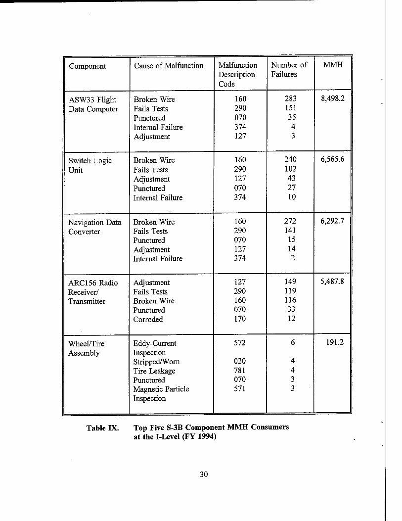
2. Top Five S-3B Component MMH Consumers at the I-Level
The ASW33 flight data computer was the number one consumer of MMHs at the
I-level. As listed in Table IX, broken wire/defective contact/connector was the main
cause of failure. ASW33 failures accounted for 8,498.2 MMHs.
The switch logic unit was the second leading consumer of MMHs. The main
cause of failure was broken wire/defective contact/connector. This type of malfunction
occurred 240 times; 6,565.6 MMHs were consumed by switch logic unit failures.
Placing third among MMH consumers was the navigation data converter. Again,
the leading cause of failure was broken wire/defective contact/connector. The navigation
data converter accounted for 6,292.7 MMHs. The ARC 156 radio receiver/transmitter was
the fourth leading MMH consumer. Adjustment/alignment was the leading cause of
failure. This was followed closely by fails diagnostic/automatic tests. ARC156 failures
consumed 5,487.8 MMHs.
Fifth on the I-level's MMH consumer list was wheel/tire assemblies. The leading
cause of failure was eddy-current inspection, followed closely by stripped/worn
discrepancies. The wheel/tire assemblies accounted for 191.2 MMHs.
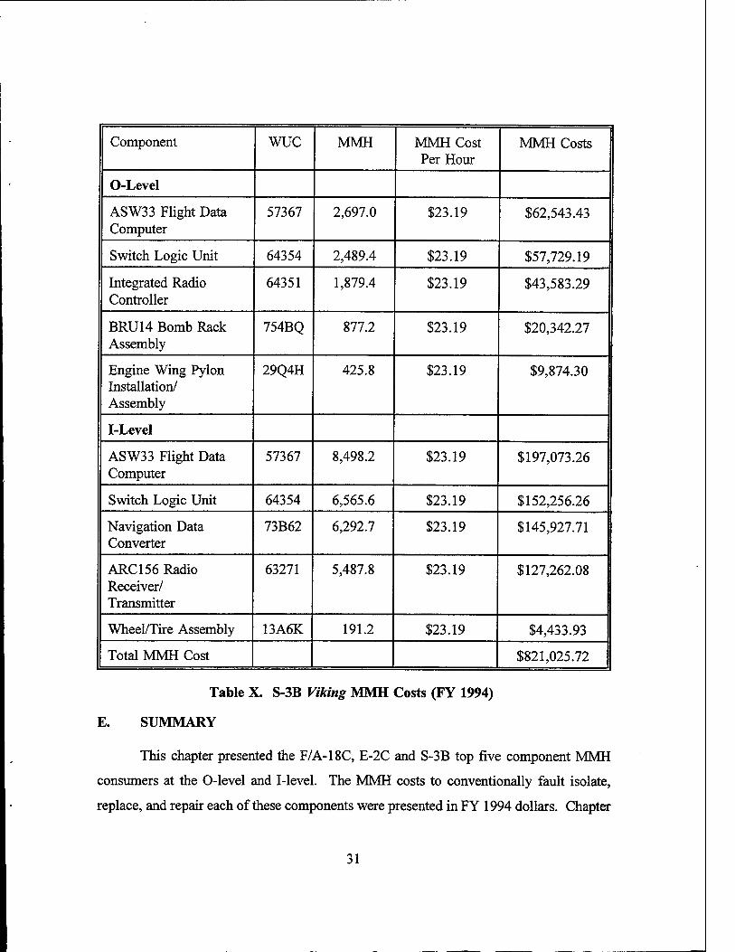
3. S-3B MMH Costs
The total MMH cost was $821,025.72 for Viking top five MMH consumers for O-
level and I-level as listed in Table X. The organizational maintenance level accounted
for 24 percent of the total cost. The ASW33 flight data computer was the number one
O-level cost driver at $62,543.43.
Intermediate maintenance level repair accounted for 74 percent of the total cost.
The ASW33 flight data computer again accounted for $197,073.26 or 24 percent of the
total cost. The ASW33 switch logic unit was the second leading cost driver at a cost of
$152,256.26. This was followed by the ASW33 navigation data converter at a cost of
$145,927.71.
29
Component Cause of Malfunction Malfunction Description Code
Number of Failures
MMH
ASW33 Flight Broken Wire 160 283 8,498.2 Data Computer Fails Tests 290 151
Punctured 070 35 Internal Failure 374 4 Adjustment 127 3
Switch Logic Broken Wire 160 240 6,565.6
Unit Fails Tests 290 102 Adjustment 127 43 Punctured 070 27 Internal Failure 374 10
Navigation Data Broken Wire 160 272 6,292.7 Converter Fails Tests 290 141
Punctured 070 15 Adjustment 127 14 Internal Failure 374 2
ARC156 Radio Adjustment 127 149 5,487.8 Receiver/ Fails Tests 290 119 Transmitter Broken Wire 160 116
Punctured 070 33 Corroded 170 12
Wheel/Tire Eddy-Current 572 6 191.2 Assembly Inspection
Stripped/Worn 020 4 Tire Leakage 781 4 Punctured 070 3 Magnetic Particle 571 3 Inspection
Table IX. Top Five S-3B Component MMH Consumers at the I-Level (FY 1994)
30
Component WUC MMH MMH Cost Per Hour
MMH Costs
O-Level
ASW33 Flight Data Computer
57367 2,697.0 $23.19 $62,543.43
Switch Logic Unit 64354 2,489.4 $23.19 $57,729.19
Integrated Radio Controller
64351 1,879.4 $23.19 $43,583.29
BRU14 Bomb Rack Assembly
754BQ 877.2 $23.19 $20,342.27
Engine Wing Pylon Installation/ Assembly
29Q4H 425.8 $23.19 $9,874.30
I-Level
ASW33 Flight Data Computer
57367 8,498.2 $23.19 $197,073.26
Switch Logic Unit 64354 6,565.6 $23.19 $152,256.26
Navigation Data Converter
73B62 6,292.7 $23.19 $145,927.71
ARC 156 Radio Receiver/ Transmitter
63271 5,487.8 $23.19 $127,262.08
Wheel/Tire Assembly 13A6K 191.2 $23.19 $4,433.93
Total MMH Cost $821,025.72
Table X. S-3B Viking MMH Costs (FY 1994)
E. SUMMARY
This chapter presented the F/A-18C, E-2C and S-3B top five component MMH
consumers at the O-level and I-level. The MMH costs to conventionally fault isolate,
replace, and repair each of these components were presented in FY 1994 dollars. Chapter
31

IV presents an overview of expert systems and introduces the readers to expert systems
users. Also, the chapter reviews some of the benefits that expert systems provide.
32
IV. EXPERT SYSTEMS OVERVIEW
Since this thesis attempts to determine if there is a benefit from developing and
applying expert systems for selective aircraft maintenance diagnostics, a brief discussion
on their characteristics, uses, and benefits is in order.
An expert system is a computer software program that attempts to replicate the
knowledge and decision making capability that human experts have acquired. Human
experts make decisions, recommendations, and perform tasks. Frequently, experts also
train others to do these same tasks or make the same decisions. Expert systems may also
be designed to perform such functions. (Bennett, 1983) A human expert is defined as
a person who, through training and experience, can perform a task with a degree of skill
that is beneficial to capture and distribute. The person filling this role is usually a top-
level task performer although sometimes capturing and automating the judgment of even
an average decision maker can be beneficial. (Prerau, 1990)
An expert system, like a human expert, often finds it necessary to extract
additional information or data from the user by asking questions related to the problem.
In many cases the system can also answer questions about why certain information is
needed and the reasoning steps used to reach a conclusion or make the recommendations
for solving the problem. (Mockler, 1987)
As compared to conventional computer programs, expert systems may be
characterized by the following distinct features. They:
1. Make decisions
2. Are based on heuristics3
3. Are more flexible
4. Can handle uncertainty
3Heuristics are defined as rules of thumb or strategies used to solve problems.
33

5. Can work with partial information, inconsistencies, or partial beliefs
6. Can provide explanations of results
7. Use symbolic reasoning
8. Are primarily declarative
9. Separate control and knowledge (Prerau,1990)
Expert systems are based primarily on symbolic reasoning about concepts rather
than numeric calculations. The systems are programmed using declarative rather than
procedural approaches. The programming techniques allow program control to be
separated from domain4 knowledge. The use of declarative knowledge separated from
program control often makes expert systems more flexible and easier to revise and update
than conventional programs. (Prerau, 1990)
1. Components of an Expert System
Any expert system consists of two components: the knowledge base and the
inference engine (Powell, 1993). The knowledge base stores the facts and heuristics of
domain experts. It also includes expert techniques on how and when to use these facts
and heuristics. The inference engine provides for system control. It applies the expert
domain knowledge (which is in the knowledge base) to what is known about the present
situation (which is the information in the working memory) to determine new information
about the domain. (Prerau, 1990)
2. Developing an Expert System
According to a model developed by Prerau, development of an expert system
consists of four elementary steps. The first step is to select a domain for the expert
system. Step two is to select one or more recognized domain experts who have credibility
in their field of work. The third step is to determine the techniques, knowledge and
4Domain is defined as the problem area of interest.
34

heuristics used by the expert(s) to perform tasks in their domain. The final step is to
design and implement a portable computer program that embodies domain expert's
techniques, knowledge and heuristics.
This requires the acquisition of the knowledge that the expert has gained through
years of experience in a selected domain and the implementation ofthat knowledge in an
expert system computer program. (Prerau, 1990)
A. USERS OF EXPERT SYSTEMS
Expert systems are widely used by private industry and to a lesser degree by
military organizations, both domestically and internationally. Automobile, aerospace,
engineering, manufacturing and medical applications have been developed.
The following paragraphs provide three specific examples of how expert systems
have been employed in the aerospace field.
1. McDonnell Douglas Corporation
Modern combat aircraft are highly complex weapon systems composed of hundreds
of black boxes and thousands of wires. This complexity makes it difficult to isolate
failures that occur within an aircraft. The difficulty in isolating a failure is magnified
when an aircraft has just completed the manufacturing process. (Lischke, 1992)
The Technical Expert Aircraft Maintenance System (TEAMS) is an interactive
system that supports the diagnosis of problems on new McDonnell Douglas aircraft.
TEAMS is an expert system that provides the aircraft mechanic with the knowledge and
experience information needed to successfully repair an aircraft. By helping mechanics
make correct repair decisions, TEAMS reduces the aircraft costs by shortening the time
needed to deliver the aircraft and reducing the inventory of spare parts required for
preparing an aircraft for delivery. TEAMS is being developed for McDonnell Aircraft's
Production Programs, including the F-15E and T-45TS. (Lischke, 1992)
35

2. Center for Artificial Intelligence Applications (CAIA)
Turbine engine design and analysis is a complex engineering process that relies on
previous field experience, testing and computer analysis. A prototype system known as
ENgine Structural Analysis Consultant (ENSAC) was developed by CAIA to help an
inexperienced structural analyst in (1) choosing the appropriate type of engine analysis to
perform, (2) choosing what analysis code to use, (3) determining data requirements, and
(4) reducing the number of common learning mistakes. (Papp, Braisted and Taylor, 1992)
ENSAC parameter inputs include data from eight engine sections, a variety of
engine components, five types of material and operating environmental conditions.
Results of the prototype system suggests that structural analysts were able to
increase their productivity. The ENSAC expert system uses: (1) menu-driven displays,
(2)is programmed with software that enables analysts to learn in an unaided manner, and
(3) uses familiar International Business Machines (IBM) personal computers.
3. United States Air Force (USAF)
F-16 Falcon electronic system's reliability and maintainability have increased since
the aircraft's acceptance by the Air Force in the mid-1970s. However, when an electronic
system or component fails, many man-hours are expended in troubleshooting, isolating
and repairing the discrepancy.
To assist USAF technicians to repair cannot duplicate (CND) and "Retest OK"
(RETOK) flight control discrepancies, Honeywell developed the Flight Control
Maintenance Diagnostic System (FCMDS) (Schroder, Smith, Bursch and Meisner 1992).
A controlled experiment was conducted at Luke Air Force Base, Arizona, from
September 1990 to June 1991. Some technicians used FCMDS and other technicians used
technical manuals to isolate and diagnose F-16 CND and RETOK discrepancies. The
experimental constraints that were imposed were that technicians had 45 minutes to
complete the maintenance actions and the work had to be completed singlehandedly
without any outside assistance.
Results of the field test show enhanced levels of performance can be achieved, at
all technician levels, by using a computer-aided maintenance system. The average fault
36

isolation time was reduced by 26 percent and diagnostic accuracy was improved by 92
percent over standard flight line practices. (Schroder, Smith, Bursch and Meisner, 1992)
B. BENEFITS OF USING EXPERT SYSTEMS
Some of the benefits that can be realized by using expert systems include: (1)
gains in productivity, (2) continuous improvement in quality, (3) improved level of human
performance, (4) decreased time to perform on-equipment/off-equipment maintenance, (5)
preservation of vital knowledge, and (6) reduction in part inventory level requirements.
The following paragraphs examine specific industrial users that have reaped
benefits of using an expert system.
1. Dupont
At Dupont's River Works in Sabine, Texas, technicians are trained to repair
computers. Since computers seldom fail, the technicians' skills were lacking in hands-on
computer repairs. To increase the technicians' proficiency in repairing computers, Dupont
developed an expert system to continuously train technicians and to maintain a real-time
database on repair procedures. The company saved $400,000 in the first year it used the
expert system and the system paid for itself in three months. (Heizer and Render, 1993)
2. Toyota Motor Company
The computerization and increasing complexity of automobiles, combined with an
insufficient number of qualified auto mechanics, proved disastrous for Toyota.
Approximately 40 percent of the parts that were removed and replaced were done so
unnecessarily and consumers were unhappy. To regain consumers' confidence, Toyota
researched and developed an Atrex expert system. Atrex helped mechanics proficiently
troubleshoot auto problems, increased their productivity ten fold by reducing the number
of troubleshooting hours and most of all-saved Toyota's reputation. (Feigenbaum,
McCorduck and Nii, 1989)
37

C. SUMMARY
This chapter provided a background and overview on expert systems. The
following chapter addresses the issue of using expert systems to fault isolate
systems/components of three aircraft.
38

MAINTENANCE MAN-HOUR COST SAVINGS USING EXPERT SYSTEMS
This chapter introduces the concept of using expert systems to help fault isolate
F/A-18C, E-2C and S-3B weapon systems and/or components. By using expert systems
to assist in the fault isolation process, there is a strong possibility that O- and I-level
maintenance man-hours (MMHs) could be reduced and MMH cost savings realized.
The chapter first documents the researchers initial attempt to assess the potential
savings in MMH using data from the NALDA and interviews with subject matter experts
from the three weapon systems. It then lays out an empirical model that was developed.
The paradigm can serve as a generic model for any type of aviation weapon system to
calculate potential cost savings from using expert systems.
To assist in determining the possibility of MMH cost savings, interviews were
conducted with Navy enlisted aircraft maintenance technicians and technical represen-
tatives. They were provided information on expert systems, their uses, associated benefits
and how this technology could assist in correcting system/component malfunctions.
The maintenance personnel were asked to screen maintenance action forms (MAFs)
at their activity, conduct brainstorming sessions with their counterparts, review
maintenance procedures and provide relative aircraft maintenance information to the
authors.
Because of the limited time allotted to thesis research in the curriculum (a six
quarter program) and the fact that this research was not sponsored, thus restricting the
amount of travel by the authors, some limitations and assumptions have been made.
Based upon our professional judgment and experience as aircraft maintenance
officers, it was assumed (through a limited sample) that the information provided by the
technicians and representatives contacted would be similar to a broader fleet-wide
response. The information is used throughout this chapter to calculate MMH cost savings
and evaluate the potential use of expert systems in the Naval aviation maintenance field.
39
A. KEY TERMS AND RATES USED TO CALCULATE MMH COST SAVINGS
Key terminology is defined in order to provide the reader with a clear
understanding of how MMH cost savings were calculated. The terms defined are: (1)
MMHs, (2) fault isolation percentage, (3) pertinency rate, and (4) efficiency rate.
1. MMHs
MMHs are the total accumulated direct labor hours expended in performing a
maintenance action. Direct MMHs are man-hours expended by assigned personnel to
complete work. This includes the functions of preparation, inspection, disassembly, fault
isolation, adjustment, replacement or reassembly of parts and calibration/tests required in
restoring an item to a serviceable status.
It also includes such tasks as checking out and returning tools, looking up part
numbers in illustrated parts breakdown manuals, transmitting required information to
supply points and completing associated documentation. (OPNAVINST 4790.2E, Volume
V)
2. Fault Isolation Percentage
Fault isolation time is the total time expended in isolating the primary cause of
malfunction. It is a subset of MMHs, and as such, is considered a percentage of MMHs.
It has been the experience of the researchers that it is not unusual for fault isolation time
to be 50-80 percent of the available MMHs expended.
For example, if 100 MMHs are expended in returning a system/component to a
serviceable status, and fault isolation time is 80 MMHs, the fault isolation percentage is
80 percent (80 MMHs divided by 100 MMHs). This is a key point, since in this study
the fault isolation percentage is a critical term used to calculate MMH cost savings.
3. Pertinency Rate
The pertinency rate is that portion of aircraft system/component failures to which
an expert system would cover the fault isolation process. It includes the fault isolation
MMH reduction rate that may be possible through the use of expert systems. Recall that
40

an expert system incorporates documented factual knowledge available to the average
technician with the heuristic knowledge of a domain expert. For example, let us say that
with factual knowledge, the average technician can correctly fault isolate 70 out of 100
components. The heuristic knowledge of a domain expert will allow an additional 15
components that previously could not be fault isolated to now be correctly diagnosed.
Therefore, with an expert system, the average technician could correctly fault isolate 85
out of 100 components. The pertinency rate in this case would then be 85 percent.
4. Efficiency Rate
The efficiency rate is the ability to correctly fault isolate aircraft system/component
failures. It encompasses using either conventional methods (as described in Chapter III)
or using expert systems.
Supporters of expert systems claim the fault isolation accuracy rate can often be
increased up to 92 percent (Schroeder, Smith, Bursch, Meisner, 1992). In other words,
an expert system's fault isolation procedures would correctly diagnose a fault nine out of
ten times. This is due in part because expert systems often provide instant access to a
knowledge base that may store years of aviation maintenance expertise.
An expert system's encapsulated knowledge can enable average technicians to
rapidly resolve complex aircraft maintenance problems. Some would argue it would be
overly optimistic to initially expect the fault isolation accuracy rate to reach the maximum
of 92 percent (cited by Schroeder, et al), for a newly developed expert system. System
accuracy would improve over time. Using prudent, but realistic figures to demonstrate
MMH cost savings, the authors chose efficiency rates of 70 and 90 percent to apply to the
examples in this chapter. Seventy percent on the low side was a realistic figure. After
all, if one assumed a rate of 50 percent (only every other time would the expert system
correctly fault isolate), it is unlikely that technicians would use such a system for long.
41
B. OVERVIEW ON CALCULATING AVERAGE MMH COST SAVINGS
For the aircraft systems and components involved in deriving average MMH cost
savings, the same steps were used to calculate the cost savings at the O- and I-levels. The
average MMH cost saving differences were due to differences between aircraft MMHs,
fault isolation percentages, and pertinency rates.
As previously stated, MMHs were extracted from the NALDA database for the
time frame October 1993 >.o September 1994. Fault isolation percentages and pertinency
rates were provided by the previously mentioned technicians and technical representatives.
The chosen e:fficienc> rates of 70 and 90 percent remain constant throughout this chapter
to compute average MMH cost savings.
Calculating Average MMH Cost Savings
There are four simple steps in calculating the average MMH cost savings listed in
the tables. They are:
• MMHs expended on a failed component multiplied by the applicable fault isolation percentage. This provides the average fault isolation man-hours.
• The average fault isolation man-hours are then multiplied by the applicable pertinency rate to derive the average pertinent man-hours.
• The average pertinent man-hours are then multiplied by the applicable efficiency rate. This produces the average man-hour savings achievable.
• The average man-hour savings achievable figures are then multiplied by the E-5 composite labor rate ($23.19 FY 1994 dollars in this case) to derive average MMH cost savings.
C. F/A-18C HORNET AVERAGE MMH COST SAVINGS
Practicality, convenience, time zones and close geographic proximity pointed the
authors in the direction of NAS Lemoore to gather research data. The AIMD assistant
aircraft maintenance officer was a former NPS graduate and familiar with the topic of
42

expert systems. He offered the quality assurance/analysis division as the best choice, in
terms of experience and expertise, to assist the authors with data assimilation.
AIMD quality assurance representatives (QARs) provided the Hornet's fault
isolation percentages and pertinency rates at the O- and I-levels. It is the author's
experience that most QARs at any AIMD have had previous O-level experience. Also,
these top performers are often among the most experienced and senior technicians in the
organization. QARs familiar with the various O- and I-level components consulted with
respective maintenance technicians who fault isolate, replace, and repair the specific
components in question.
1. O-Level Cost Savings
At the O-level, technicians determined that expert systems would not be applicable
to fault isolate the top five component MMH consumers. Their experience indicated the
top five component cause of malfunctions (corrosion, nicked/chipped, cracked/crazed,
wear, defective connections) were readily identified using conventional methods.
Therefore, no fault isolation percentages or pertinency rates applied at the O-level.
As a result, no F/A-18C Hornet average MMH cost savings were computed for the O-
level.
2. I-Level Cost Savings
At the I-level, the first three component MMH consumers were associated with the
weapons control system (WUC 74). These components included the APG65 radar
transmitter, APG65 receiver exciter and APG65 antenna. The fourth and fifth leading
component MMH consumers were the ASW44 pitch-roll-yaw computer and the ARC
radio receiver/transmitter. The technicians estimated they spent 25 percent of their time
fault isolating these components.
Pertinency rate estimates varied amongst components. For the APG65
components, technicians assigned a 75 percent pertinency rate, indicating that an average
technician or domain expert assistance was required 75 percent of the time in fault
isolation. They estimated a 50 percent pertinency rate for the ASW44 pitch-roll-yaw
computer and a 30 percent pertinency rate for the ARC radio receiver/transmitter. This
43

is due to the greater effectiveness of current diagnostic methods, repair manuals and less
complexity involved with these systems.
Table XI lists the cost saving estimates for the F/A-18C Hornet if expert systems
were employed at the I-level. The computations yielded an annual MMH cost savings
range of $108,396.34 to $139,366.73 using 70 and 90 percent expert system efficiency
rates. The three APG65 components account for approximately 84 percent of this savings,
or between $91,225.40 and $117,289.80.
D. E-2C HA WKEYE AVERAGE MMH COST SAVINGS
Again, practicality, convenience, time zones and geographic proximity pointed the
authors in the direction of NAS Miramar as the logical choice for gathering E-2C
Hawkeye data. QARs from AIMD NAS Miramar provided the Hawkeye 's maintenance
information. These technicians possessed a comprehensive knowledge and experience
base of the Hawkeye's avionics, power plants, airframes and electrical systems at the O-
and I-levels.
In addition to O-level avionics/armament and quality assurance/analysis division
experience, the I-level avionics technician has supervised the operation and maintenance
of Radar Countermeasures (RADCOM) test benches and module/micro-miniature repair
branch at the I-level. He was familiar with each of the top five component MMH
consumers and their respective fault isolation/replacement/repair procedures at the I-level.
1. O-Level Cost Savings
The O-level's top five component cause of malfunctions were not considered
overly complex to fault isolate. Based on the technicians' input, an expert system was
not needed to help fault isolate these five systems/components. Chapter III, Table V may
be consulted to refresh the readers' memory of the Hawkeye's O-level maintenance data.
The propeller/power plant systems technicians foresaw no expert system applica-
bility for the variable pitch propeller, power plant installation/engine assembly or propeller
control assembly. These were the first, second and fifth highest MMH consumers,
44

respectively. They believed the MIMs adequately document the commonly encountered
malfunctions and corrective action procedures for the related systems/components.
The electrical systems technician did not feel expert system technology was
applicable to the utility light, the third highest MMH consumer. This was due to the
simplistic light design and the ease to rapidly correct related malfunctions.
45
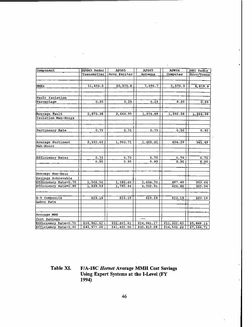
Component APG65 Radar APG65 APG65 ASW44 ARC Radio Transmitter Rcvr Exciter Antenna Computer Rcvr/Trans
MMHs 11,493.5 10,579.8 7,898.7 5,570.3 4,819.9
Fault Isolation Percentage 0.25 0.25 0.25 0.25 0.25
Average Fault 2,873.38 2,644.95 1,974.68 1,392.58 1,204.98 Isolation Man-Hours
Pertinency Rate 0.75 0.75 0.75 0.50 0.30
Average Pertinent 2,155.03 1,983.71 1,481.01 696.29 361.49 Man-Hours
Efficiency Rates 0.70 0.70 0.70 0.70 0.70 0.90 0.90 0.90 0.90 0.90
Average Man-Hour
Savings Achievable Efficiency Rate=0.70 1,508.52 1,388.60 1,036.70 487.40 253.04 Efficiency Rate=0.90 1,939.53 1,785.34 1,332.91 626.66 325.34
E-5 Composite $23.19 $23.19 $23.19 $23.19 $23.19 Labor Rate
Average MMH
Cost Savings ■ —
Efficiency Rate=0.70 $34,982.62 $32,201.61 $24,041.17 $11,302.83 $5,868.11 Efficiency Rate=0.90 $44,977.66 $41,402.06 $30,910.08 $14,532.22 $7,544.71
Table XI. F/A-18C Hornet Average MMH Cost Savings Using Expert Systems at the I-Level (FY 1994)
46
The airframes system technician also felt that an expert system was not applicable
to the rudder system, the fourth highest MMH consumer. This was due to the nature of
commonly encountered malfunctions and the adequacy of MMs to help fault isolate/
replace/repair rudder system components.
2. I-Level Cost Savings
The I-level avionics technician foresaw potential MMH cost savings for the two
azimuth range indicators (WUCs 726J2, 726J4) if expert systems were used at the I-level.
He indicated that 65 percent of the MMHs were attributable to fault isolation.
These items are fairly time consuming to diagnose. A 35 percent pertinency rate was
assigned for the expert system. The MIMs and current diagnostic methods are fairly
effective for these components. The combined MMH cost savings for these two
components would then yield between $27,190.51 and $34,959.23 annually.
Records indicate very little time was spent fault isolating the AIC14 ICS control
(approximately 10 percent). This was due to rapid and effective diagnosis when the
RADCOM test bench was used. Thus, expert systems were not needed to facilitate the
ICS control maintenance effort. Fault isolation percentages and pertinency rates were not
applicable.
The digital data converter and computer are also tested on the RADCOM test
benches. Technicians estimated a 40 percent fault isolation rate of overall MMHs and a
50 percent pertinency rate due to the components' complexity. The combined MMH cost
savings for these components only yield $66.88 to $85.99 annually because the
components failed infrequently.
The azimuth range indicator components are part of the larger main display unit
(MDU) systems in the aft crew area of the E-2C. These units are being replaced by the
newer enhanced main display unit (EMDU) systems. There was not any available EMDU
data at NALDA since these units were still under contract support.
AIMD did not possess the repair capability for the EMDU systems, but there was
a tentative test program system anticipated for the RADCOM test benches. This means
47

the units are presently beyond the repair capability of I-level maintenance and are
forwarded to the D-level for repair.
At the D-level, Grumman Aerospace Company technical representatives perform
the diagnosis and repair of EMDUs using laptop computer technology. The avionics
technician anticipated increased EMDU fault isolation percentages and pertinency rates
upon entrance into the AIMD repair pipeline. Table XII displays the potential Hawkeye 's
MMH cost savings at the I-level.
E. S-3B VIKING AVERAGE MMH COST SAVINGS
NAS North Island was chosen as the site for gathering S-3B data for the same
reasons as the F/A-18C and E-2C, its geographic closeness. The authors chose VS-33 as
the representative O-level activity. We knew the maintenance/material control officer
(MMCO) and the squadron was not deployed. The MMCO recommended that the authors
contact Mr. Jim Vizzard (Lockheed technical representative) at AIMD. He has a
reputation as the Vikings' I-level expert.
1. O-Level Cost Savings
The O-level avionic and electrical system technicians indicated an expert system
would be extremely beneficial in fault isolating the ASW33 flight data computer broken
wire/defective contact/connection cause of malfunction.
They felt an expert system would be beneficial because the number of MIMs that
must be consulted, to trace out computer wire bundle runs, made fault isolation a complex
and time consuming process. Using an expert system would reduce the MIM require-
ments. It was believed that fault isolation time could be significantly reduced.
Also, by using diagrams and pictures in the expert system, the location of plugs
and connectors could be readily identified. This would be especially helpful to
inexperienced technicians. It would allow them to rapidly locate potential computer
related problems without the aid of an experienced technician as is often the case now.
48

Component Az Range AIC14 ICS Az Range Dgtl Data Dgtl Data Indicator Control Indicator Converter Computer
MMHs 7,160.5 2,491.9 202.2 17.0 3.6
Fault Isolation 0.65 0.10 0.65 0.40 0.40 Percentage
Average Fault 4,654.33 249.19 131.43 6.80 1.44 Isolation Man-Hours
Pertinency Rate 0.35 0.00 0.35 0.50 0.50
Average Pertinent 1,629.01 0.00 46.00 3.40 0.72 Man-Hours
Efficiency Rates 0.70 0.70 0.70 0.70 0.70 0.90 0.90 0.90 0.90 0.90
Average Man-Hour
Savings Achievable Efficiency Rate=0.70 1,140.31 0.00 32.20 2.38 0.50 Efficiency Rate=0.90 1,466.11 0 41.40 3.06 0.65
E-5 Composite $23.19 $23.19 $23.19 $23.19 $23.19 Labor Rate
Average MMH
Cost Savings Efficiency Rate=0.70 $26,443.78 $0.00 $746.73 $55.19 $11.69 Efficiency Rate=0.90 $33,999.15 $0.00 $960.08 $70.96 $15.03
Table XII. E-2C Hawkeye Average MMH Cost Savings Using Expert Systems at the I-Level (FY 1994)
49

A third expert system benefit could be the reduction of A-799 WRAs that were
unnecessarily removed and replaced in fault isolating ASW33 flight data computer
discrepancies. A-799s contributed only three percent to the total ASW33 flight data
computer failures (34 A-799s divided by 1155 ASW33 flight data computer failures in
FY 1994).
The technicians estimated a fault isolation percentage of 60 percent and a
pertinency rate of 80 percent due to system complexity and the effectiveness of technical
publications. Based on these estimates, the ASW33 flight data computer MMH yearly
cost savings would be between $21,014.59 and $27,018.76.
The switch logic unit and integrated radio controller were related system units.
They were both subject to the same broken wire/defective contact/connection cause of
malfunction. Fault isolation time could be reduced by the use of an expert system
according to the technicians. Their reasoning was similar to the previous fault isolation
problem for the ASW33 flight data computer. In addition, it was also pointed out that
expert system usage would be beneficial in fault isolating the "no output" cause of
malfunction.
This analogy seemed logical because "no output" was a leading cause of failure
for the switch logic unit and integrated radio controller. Technicians stated that the "no
output" malfunction routinely consumed a large amount of MMHs. Their experience
indicated that the fault isolation process was lengthy in trying to narrow the common
failure causes to such items as a defective circuit breaker, blown fuse, open ground, bad
power supply or combination.
An expert system that stores the indications associated with the causes of
component failure and is able to determine the correct remedies to make the systems or
components serviceable would be valuable. Both technicians agreed such technology
could reduce the number of MMHs.
For example, with a fault isolation percentage and pertinency rate for the Viking
switch logic unit and integrated radio controller of 80 percent each, the combined MMH
50

cost savings would be between $45,387.99 to $58,355.98. Table XIII lists the Viking's
potential O-level cost savings.
2. I-Level Cost Savings
The I-level avionics expert was a Lockheed technical representative assigned to
AIMD North Island. He spent most of his time fault isolating WRAs/SRAs. He has been
involved with S-3B repair for many years. His current specialty is avionics repair using
the Versatile Avionics Shop Test (VAST) bench system. VAST is capable of diagnosis
and repair of a wide variety of aircraft weapon systems.
VAST benches exist both ashore and afloat and have been in existence for many
years. They are physically large and complex, requiring considerable set-up time. They
are scheduled to be replaced by the modern Consolidated Automated Support System
(CASS) in November 1995.
Out of the "Top 5" Viking I-level component MMH consumers, the first four
WRAs are diagnosed and repaired using the VAST test bench. The four include the
ASW33 flight data computer, the switch logic unit, the navigational data converter and
the ARC 156 radio receiver/transmitter. All of these components suffer from similar
malfunctions: a broken wire/ defective contact/connection, failed diagnostic/automatic
tests, and improper adjustment/alignment. These malfunctions produce the majority (over
93 percent) of associated discrepancies for these components.
Since the technical representative spent most of his time fault isolating
WRAs/SRAs on the VAST bench, he recommended fault isolation time as 60 percent of
the MMHs. His pertinency rate was estimated to be 15 percent. He anticipated more
benefits from expert systems once the new CASS replaces the much older VAST bench.
The fact that the VAST bench will soon be replaced is a prime reason for not considering
development of an expert system for it. There is neither the time necessary for
development nor a large enough return on investment.
Calling upon the technical representative's comprehensive experience with the S-
3B Viking, an inquiry was also made into the applicability of an expert system for
diagnosing the fifth leading MMH consumer, wheel/tire assemblies and related
51

Component ASW33 Flight Switch Logic Integrated Radio
Data Computer Unit Controller
-
MMHs 2,697.0 2,489.4 1,879.4
Fault Isolation 0.60 0.80 0.80
Percentage
Average Fault 1,618.20 1,991.52 1,503.52
Isolation Man-Hours
Pertinency Rate 0.80 0.80 0.80
Average Pertinent 1,294.56 1,593.22 1,202.82
Man-Hours
Efficiency Rates 0.70 0.70 0.70
0.90 0.90 0.90
Average Man-Hour
Savings Achievable
Efficiency Rate=0.70 906.19 1,115.25 841.97
Efficiency Rate=0.90 1,165.10 1,433.89 1,082.53
E-5 Composite $23.19 $23.19 $23.19
Labor Rate
Average MMH
Cost Savings
Efficiency Rate=0.70 $21,014.59 $25,862.68 $19,525.31
Efficiency Rate=0.90 $27,018.76 $33,252.01 $25,103.97
Table XIII. S-3B VikingMMH Cost Savings Using Expert Systems at the O-Level (FY 1994)
52

components. He believed these items were solvable using conventional fault isolation
methods rather than expert systems. This makes sense. The majority of conventional
fault isolation methods used on these components are eddy-current and magnetic particle
inspections or the MIMs. They provide an adequate fault isolation capability.
Based upon the information related to the first four top MMH consumers at the
I-level, expert systems incorporation could save an estimated $39,218.72 to $50,424.06
in MMH costs annually. While this is not overwhelming savings, it is primarily due to
the current VAST limitations (20 year old design, complexity, lengthy set up and run
time). Benefits are anticipated to increase with the introduction of CASS. Table XIV
illustrates the procedures used for determining MMH cost savings.
After examining the results of the work that produced Tables XI-XIV, the authors'
concluded that the method used had weaknesses. The data was extrapolated from
NALDA and fault isolation percentages and pertinency rates were based on phone
interviews. The question was raised as to whether this was a truly objective and
quantitative method or was the method too subjective and qualitative. It sorted out to be
a combination of both methods.
Much was learned in the gathering of data and interviews. In critically examining
the initial effort, the researchers were able to formulate a basic empirical model for
estimating potential MMH cost savings by using expert systems to assist in the fault
isolation process. A S-3B Viking I-level domain expert assisted in the development of the
model and furnished data used in the following example.
F. THE SfflRKEY-SCHANZ EXPERT SYSTEM MAINTENANCE MAN- HOUR COST SAVINGS MODEL
In the course of this research, it became evident that the S-3B Viking's I-level
process presented an opportunity for developing an empirical model that could be used
to assess potential MMH cost savings when an expert system is incorporated into the
diagnostic process. Each of the top four I-level MMH consumers for the S-3B is repaired
53

Component ASW33 Flight Switch Logic Navigation Data ARC156 Radio Data Computer Unit Converter Rcvr/Trans
MMHs 8,498.2 6,565.6 6,292.7 5,487.8
Fault Isolation 0.60 0.60 0.60 0.60 Percentage
Average Fault 5,098.92 3,939.36 3,775.62 3,292.68 Isolation Man-Hours
Pertinency Rate 0.15 0.15 0.15 0.15
Average Pertinent 764.84 590.90 566.34 493.90 Man-Hours
Efficiency Rates 0.70 0.70 0.70 0.70 0.90 0.90 0.90 0.90
Average Man-Hour
Savings Achievable Efficiency Rate=0.70 535.39 413.63 396.44 345.73 Efficiency Rate=0.90 688.35 531.81 509.71 444.51
E-5 Composite $23.19 $23.19 $23.19 $23.19 Labor Rate
Average MMH
Cost Savings Efficiency Rate=0.70 $12,415.62 $9,592.14 $9,193.45 $8,017.51 Efficiency Rate=0.90 $15,962.93 $12,332.76 $11,820.14 $10,308.23
Table XIV. S-3B Viking Average MMH Cost Savings Using Expert Systems at the I-Level (FY 1994)
54

on the VAST bench by maintenance technicians. In a significant number of cases, a
domain expert is required to assist in determining the fault. In this case, the domain
expert (a Lockheed technical representative from NAS North Island) explained that he
would group faulty components into four categories, based upon the amount of time
consumed in fault isolation. The four categories have been designated as average,
difficult, complex and unrepairable.
An average component is one which current procedures (i.e., publications, test
programs, and average technician aptitude) result in the successful isolation and repair of
the malfunction. For model purposes, the authors designated the MMH associated with
an average component as factor A.
A difficult component is a component requiring factor A MMHs, plus the
additional fault isolation time of a human expert (highly experienced Naval technician or
NETS/CETS technical representative) to successfully repair the component. A difficult
component's MMHs are designated as factor B.
A complex component refers to a component which is eventually successfully
repaired at the I-level, requiring both factors A and B, plus additional fault isolation time
by a domain expert. A complex component's MMHs are designated as factor C.
An unrepairable component refers to a component that is considered unrepairable
at the I-level. It is comprised of the time associated with factors A, B, and C, plus
additional time up to a maximum preset number of fault isolation hours. These
components are considered beyond the organization's repair capability and are forwarded
to the next higher repair facility. They are termed "BCM", beyond the capability of
maintenance. MMHs associated with an unrepairable component is designated as factor
D.
The Expert System MMH Cost Savings Model that follows consists of an eight
step process. The discussion below defines each step in the model. S-3B data is then
used to demonstrate the application of each step.
55

Step 1
Assign fault isolation times to each component category (factors A, B, C, and D). The time assignments are determined by grouping components in the four categories and analyzing the fault isolation times for each category. While the example that follows uses set times, the reader should understand that these times may vary for other aircraft systems based upon real world experience and practices.
For the S-3B top four MMH consumers, average components (factor A) make up
60 percent of all components. Average components are fault isolated, on average, in one
hour. Malfunctions of this type consist primarily of components which involve straight-
forward diagnosis and replacement of a single SRA.
Difficult components (factor B) make up 30 percent of all components. The
average fault isolation time for this category was three hours. Thus, total fault isolation
time averages four hours (1 hour (A) + 3 hours (B)) for components in this category.
These components often entail some ambiguities in the fault isolation process, sometimes
being isolated to more than one SRA. They usually involve basic SRA replacement.
Complex components (factor C) make up approximately five percent of all
components. The fault isolation time for this category was two additional hours. Total
fault isolation time averages six hours (1 hour (A) + 3 hours (B) + 2 hours (C)) for
components in this category. For example, these discrepancies may entail difficult to
diagnose chassis wiring problems. But they are still repairable if adequate expertise is
available.
Unrepairable components (factor D) make up five percent of the components. The
fault isolation time policy for these components allows for an additional two hours before
the components are determined to be unrepairable. Total fault isolation time for
unrepairable components averaged eight hours (1 hour (A) + 3 hours (B) + 2 hours (C)
+ 2 hours (D)). These components may involve chassis wiring problems. Fault isolation
is complex and time consuming, often requiring more than eight hours to accomplish.
After eight hours, the technical representative deems the component beyond economical
repair at the I-level and the component is forwarded to the D-level.
56

Step 2
Assign a MMH cost per hour for each of the fault isolation factors defined in step 1.
For our model, the MMH cost per hour is referred to as factor M. The MMH cost
per hour for the various military paygrades can be determined by consulting the
NAVCOMPT Notice 7041. Also, Table I located in Chapter II of this study, depicts the
MMH cost per hour calculation process.
The MMH cost per hour is $23.19 (FY 1994) based on an E-5 paygrade for this
example model.
Step 3
Determine the total number of component failures over a given time frame.
The total number of component failures is designated as factor N. The total
number of failures can be extracted from the NALDA data base. The time frame used
to determine N is assigned by the person conducting the study.
The example model uses 1,000 failed components over a one year period.
Step 4
Allocate the percentage of the total number of component failures to each of the four categories.
A domain expert would determine these percentages based on personal experience
with the test facilities, technicians, and components. The domain expert would also
consider local policy as to when components are considered beyond economic repair of
the maintenance organization.
For this model the following variables are assigned. Pj is the percentage of failed
components associated with factor A. P2 is the percentage of failed components
associated with factor B. P3 is the percentage of failed components associated with factor
C. P4 is the percentage of failed components associated with factor D.
As discussed under step 1, the domain expert assigned a category breakout of the
following in our example: P, is 60 percent (i.e., 60 percent of all the components were
57
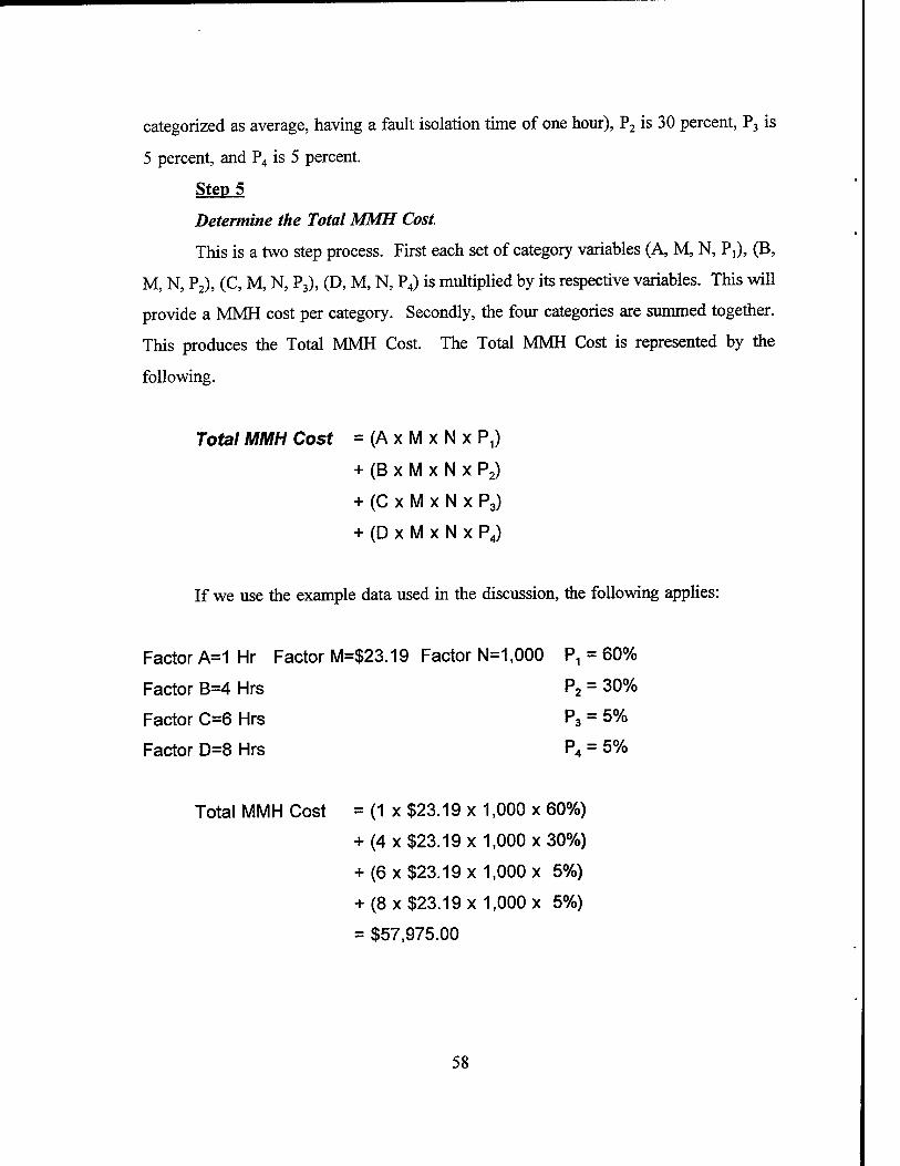
categorized as average, having a fault isolation time of one hour), P2 is 30 percent, P3 is
5 percent, and P4 is 5 percent.
Step 5
Determine the Total MMH Cost.
This is a two step process. First each set of category variables (A, M, N, P,), (B,
M, N, P2), (C, M, N, P3), (D, M, N, P4) is multiplied by its respective variables. This will
provide a MMH cost per category. Secondly, the four categories are summed together.
This produces the Total MMH Cost. The Total MMH Cost is represented by the
following.
Total MMH Cost = (A x M x N x P,)
+ (B x M x N x P2)
+ (C x M x N x P3)
+ (D x M x N x P4)
If we use the example data used in the discussion, the following applies:
Factor A=1 Hr Factor M=$23.19 Factor N=1,000 Pn = 60%
Factor B=4 Hrs P2 = 30%
Factor C=6 Hrs P3 = 5%
Factor D=8 Hrs P4 = 5%
Total MMH Cost = (1 x $23.19 x 1,000 x 60%)
+ (4 x $23.19x1,000x30%)
+ (6 x $23.19 x 1,000 x 5%)
+ (8 x $23.19 x 1,000 x 5%)
= $57,975.00
58

This amount is the total MMH cost at the I-Ievel for all of the top four
components.
Step 6
Determine the impact of applying an expert system to assist in the fault isolation process.
This figure will be a percentage of the overall fault isolation time for each
category (factors A, B, C, D). The reduced factors are designated as: factor Ax, factor
Bj, factor Cj, and possibly factor DL
The domain expert believed that for average components, factor A was already at
a minimum in terms of fault isolation efficiency. It would benefit little from expert
system technology. However, when applying an expert system to the fault isolation
process, we would expect that each category of component may expect some improvement
(i.e.,reduction) in the fault isolation time. This is because, even for average components,
when examining the process domain experts will likely add some heuristics to the fault
isolation process, thus improving it. Difficult and complex components (factors B and
C) are the categories that would benefit the most from expert system technology for the
S-3B components used in this example. Previous experience of the thesis advisor suggests
that factor B's and factor C's fault isolation times could be expected to be reduced, in the
range of 30 to 90 percent by applying the knowledge of an expert system.
First, using a conservative approach based on the assumption that expert system
technology would reduce the fault isolation time of factor B and factor C each by 30
percent, factors B! and Q are calculated as follows:
Factor A =1 Hr = Factor A,
Factor B = Factor A +3 Hrs =4 Hrs
Factor B, =1 Hr +3 Hrs(100%-30%)=1 Hr +2.1 Hrs =3.1Hrs
Factor C = Factor A + Factor B +2 Hrs =6 Hrs
Factor C, =1 Hr +3 Hrs(100%-30%) +2 Hrs(100%-30%) =1 Hr + 2.1 Hr +1.4 Hrs=4.5 Hrs
59
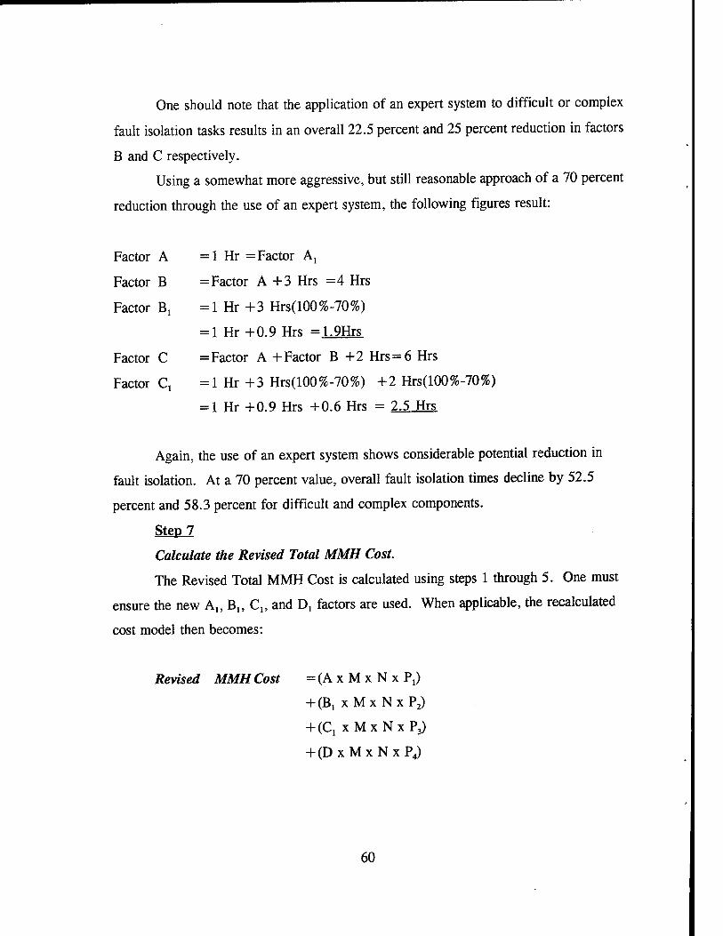
One should note that the application of an expert system to difficult or complex
fault isolation tasks results in an overall 22.5 percent and 25 percent reduction in factors
B and C respectively.
Using a somewhat more aggressive, but still reasonable approach of a 70 percent
reduction through the use of an expert system, the following figures result:
Factor A =1 Hr = Factor Ax
Factor B = Factor A +3 Hrs =4 Hrs
Factor Bx =1 Hr +3 Hrs(100%-70%)
= 1 Hr+0.9 Hrs =1.9Hrs
Factor C = Factor A + Factor B +2 Hrs = 6 Hrs
Factor C, =1 Hr +3 Hrs(100%-70%) +2 Hrs(100%-70%)
= 1 Hr +0.9 Hrs +0.6 Hrs = 2.5 Hrs
Again, the use of an expert system shows considerable potential reduction in
fault isolation. At a 70 percent value, overall fault isolation times decline by 52.5
percent and 58.3 percent for difficult and complex components.
Step 7
Calculate the Revised Total MMH Cost.
The Revised Total MMH Cost is calculated using steps 1 through 5. One must
ensure the new A„B„C„ and D1 factors are used. When applicable, the recalculated
cost model then becomes:
Revised MMH Cost = (A x M x N x P,)
+ (B,xMxNxP2)
+ (Cj xMxNxP3)
+ (DxMxNxP4)
60

Using the 30 percent improvement in fault isolation gained using an expert system, the
revised MMH cost would be as follows:
Example data:
Factor A = 1 Hr Factor M = $23.19 Factor N = 1,000 P, = 60%
Factor B, = 3.1 Hrs P2 = 30%
Factor C, = 4.5 Hrs P3 = 5%
Factor D = 8 Hrs P4 = 5%
Revised MMH Cost = (1.0 x $23.19 x 1,000x60%)
+ (3.1 x $23.19 x 1,000x30%)
+ (4.5 x $23.19 x 1,000 x 5%)
+ (8.0 x $23.19 x 1,000 x 5%)
= $49,974.45
The MMH cost savings from using an expert system estimated to provide a 30
percent would be 13.8 percent. Recall this savings is figured using only the top four
MMH component consumers. Using the higher 70 percent factor, the result would be:
Factor A = 1 Hr Factor M = $23.19 Factor N = 1,000 P, = 60%
Factor B1 = 1.9 Hrs P2 = 30%
Factor C, = 2.5 Hrs P3= 5% Factor D = 8 Hrs P4= 5%
Revised MMH Cost = (1.0 x $23.19 x 1,000x60%)
+ (1.9 x $23.19 x 1,000x30%)
+ (2.5 x $23.19 x 1,000 x 5%)
+ (8.0 x $23.19 x 1,000 x 5%)
- = $39,307.05
61

The MMH cost savings from using an expert system estimated to provide a 70
percent would be 32.2 percent. Recall this savings is figured using only the top four
MMH component consumers.
Step 8
Determine the Expert System MMH Cost Savings.
The Expert System Cost Savings is determined by subtracting the Revised MMH
Cost from the Total MMH Cost, i.e.,Expert System MMH Cost Savings =Total MMH
Cost - Revised MMH Cost.
The S-3B I-level model expert system MMH cost savings is derived as follows:
Using a 30 percent MMH reduction:
Expert system MMH cost savings =
$57,975.00
$49,974.45
$ 8.000.55 savings
Using a 70 percent MMH reduction:
Expert system MMH cost savings =
$57,975.00
$39,307.05
$18.667.95 savings
Table XV summarizes the MMH and MMH cost savings from using an expert
system to fault isolate I-level discrepancies on the S-3B.
Factors D and Dl are assumed to be constant and beyond the range of expert
system improvement since these components are beyond the economical repair capability
of the domain expert.
62

Original MMHs
MMHs
Saved
MMH Cost Per
Hour
Cost Savings
%of MMHs Saved
Expert System Impact of 30%
2,500 MMHs
345 MMHs
$23.19 $8,000.55 13.8%
Expert System Impact of 70%
2,500 MMHs
805 MMHs
$23.19 $18,667.95 32.2%
Table XV. Expert System Impact on S-3B MMHs and MMH Cost Savings
Another way is to look at the savings on a per component basis. The example
model consists of 1,000 components. The average cost savings per component is as
follows:
The average MMH cost per component was $57.98.
Using a 30 percent MMH reduction:
$8,000.55/1,000 components = $8.00/component.
This represents a 13.8 percent savings per component
Using a 70 percent MMH reduction:
$18,667.95/1,000 components = $18.67/component
This represents a 32.2 percent savings per component.
63

The examples used in the model are presented, in condensed versions, for both a
30 and 70 percent MMH reduction in Figures 1 and 2 at the end of this chapter.
G. SUMMARY
This chapter documented the potential applicability of expert systems to shorten
the fault isolation time for specific aircraft components. It documents the initial approach
taken. It was presented to serve as a demonstration of the kind of path future researchers
may initially wish to consider, but as was learned in this research, they should not. The
second portion of the chapter presented an empirical model that was developed to estimate
the MMH cost savings from using expert systems technology. Chapter VI delineates
research questions and answers, conclusions, lessons learned, and recommendations for
further research.
64
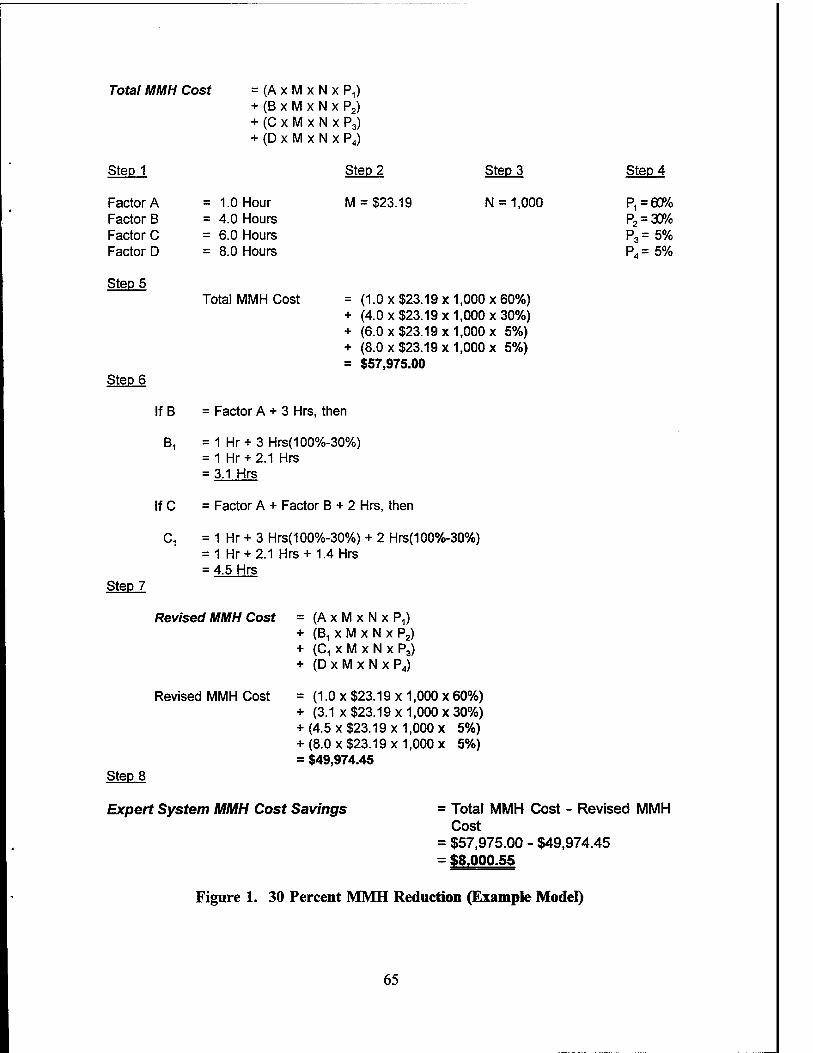
Total MMH Cost = (AxMxNxP,) + (B x M x N x P2) + (C x M x N x P3) + (D x M x N x P4)
Step 1 Step 2 Step 3 Step 4
Factor A = 1.0 Hour M = $23.19 N = 1,000 ^=60% Factor B = 4.0 Hours P2 = 30% Factor C = 6.0 Hours P3= 5% Factor D = 8.0 Hours P4= 5%
Step 5 Total MMH Cost = (1.0 x $23.19x1,000x60%)
+ (4.0 x $23.19 x 1,000 x 30%) + (6.0 x $23.19 x 1,000 x 5%) + (8.0 x $23.19 x 1,000 x 5%) = $57,975.00
Step 6
If B = Factor A + 3 Hrs, then
B1 = 1 Hr + 3 Hrs(100%-30%) = 1 Hr + 2.1 Hrs = 3.1 Hrs
If C = Factor A + Factor B + 2 Hrs, then
C, = 1 Hr + 3 Hrs(100%-30%) + 2 Hrs(100%-30%) = 1 Hr + 2.1 Hrs+1.4 Hrs = 4.5 Hrs
Step 7
Revised MMH Cost = (AxMxNxP,) + (B1 x M x N x P2) + (C, x M x N x P3) + (DxMxNxPJ
Revised MMH Cost = (1.0 x $23.19x1,000x60%) + (3.1 x $23.19 x 1,000 x 30%) + (4.5 x $23.19 x 1,000 x 5%) + (8.0 x $23.19 x 1,000 x 5%) = $49,974.45
Step 8
Expert System MMH Cost Savings = Total MMH Cost - Revised MMH Cost
= $57,975.00 - $49,974.45 = $8.000.55
Figure 1. 30 Percent MMH Reduction (Example Model)
65

Total MMH Cost
Step 1
Factor A Factor B Factor C Factor D
= 1.0 Hour = 4.0 Hours = 6.0 Hours = 8.0 Hours
= (AxMxNxP,) + (B x M x N x P2) + (C x M x N x P3) + (D x M x N x P4)
Step 2
M = $23.19
Step 3
N = 1,000
Step 4
^=60% P2 = 30% P3= 5% P4= 5%
Step 5
Step 6
Step 7
Total MMH Cost = (1.0 x $23.19 x 1,000 x 60%) + (4.0 x $23.19 x 1,000 x 30%) + (6.0 x $23.19 x 1,000 x 5%) + (8.0 x $23.19 x 1,000 x 5%) = $57,975.00
If B = Factor A + 3 Hrs, then B, = 1 Hr + 3 Hrs(100%-70%)
= 1 Hr +0.9 Hrs = 1.9 Hrs
If C = Factor A + Factor B + 2 Hrs, then C, = 1 Hr + 3 Hrs(100%-70%) + 2 Hrs(100%-70%)
= 1 Hr + 0.9Hrs + 0.6 Hrs = 2.5 Hrs
Revised MMH Cost
Revised MMH Cost
= ( A x M x N x P,) + (B, x M x N x P2) + (C1xMxNxP3) + ( D x M x N x P4)
= (1.0 x $23.19 x 1,000 x 60%) + (1.9 x $23.19 x 1,000 x 30%) + (2.5 x $23.19 x 1,000 x 5%) + (8.0 x $23.19 x 1,000 x 5%) = $39,307.05
Step 8
Expert System MMH Cost Savings = Total MMH Cost Cost
= $57,975.00 - $39,307.05 = $18.667.95
Revised MMH
Figure 2. 70 Percent MMH Reduction (Example Model)
66

VI. RESEARCH QUESTIONS AND ANSWERS/CONCLUSIONS/ LESSONS LEARNED/RECOMMENDATIONS
Naval aviation maintenance managers are responsible for ensuring aircraft
maintenance continues to be performed in a safe, efficient manner. This proves to be a
continual challenge considering declining DOD resources, the decommissioning of aircraft
squadrons and a general reduction in forces.
Maintenance managers must continually seek new ways to optimize scarce
resources and assist technicians with maintaining aircraft systems/components at all three
maintenance levels. Currently, aviation maintenance technicians and technical
representatives use conventional fault isolation methods to return aircraft
systems/components to a functional status.
These conventional fault isolation methods consume an enormous amount of
MMHs. Since both authors are experienced aviation maintenance managers, the decision
was made to investigate a potential resource to possibly reduce the consumption of
MMHs. This is why the authors chose to introduce the concept of applying expert
systems to help diagnosis aircraft discrepancies. The primary objective of this research
was to determine a process for determining the impact on direct labor MMHs of applying
expert systems to assist in diagnosis of aircraft discrepancies. The secondary objective
of this research was to identify direct labor MMH costs associated with Hornet, Hawkeye,
and Viking aircraft at the organizational and intermediate maintenance levels.
The primary research question addressed was:
• What is the empirical model for deriving the potential direct labor MMH cost savings by using expert systems to assist fault isolation of Hornet, Hawkeye and Viking systems/components?
The secondary research questions addressed were:
• What are some of the potential benefits of using expert systems in the Naval aviation maintenance field?
67

• What are the top five component MMH consumers at the organizational maintenance level for the Hornet, Hawkeye and Viking aircraft during FY 1994?
• What are the top five component MMH consumers at the intermediate maintenance level for the Hornet, Hawkeye and Viking aircraft during FY 1994?
• What are the direct labor MMH costs, using conventional fault isolation methods to identify failed components, for the three aircraft during FY 1994?
A. RESEARCH QUESTIONS AND ANSWERS
This section provides the answers to the primary and secondary research questions.
Can a model be developed to derive the potential direct labor MMH cost savings by using expert systems to assist fault isolation of Hornet, Hawkeye and Viking systems/components?
It was found that it was possible to develop such a model. The Shirkey-Schanz
Expert System Maintenance Man-Hour Cost Savings Model was developed by the authors
to determine the potential direct labor MMH cost savings from using expert systems to
fault isolate aircraft systems/components. The empirical model groups components into
categories based upon their average fault isolation times. The component categories were
designated average, difficult, complex, or unrepairable. Each category was assigned an
average fault isolation time to repair that category of component based upon a domain
expert's recommendation. In the example used for this research, if a component required
over eight hours of repair it was considered beyond the economical repair capability of
the maintenance organization. Such components were classified in the unrepairable
category.
The difficult and complex component categories were chosen as targets for
potential expert system development. These two categories were primarily chosen
because:
68

1. These components require significantly greater fault isolation times;
2. A key reason for this is that there is a lack of factual/documented knowledge available to the technician;
3. The heuristic knowledge of a technical representative is usually required to correctly fault isolate these components within a reasonable period of time.
The empirical model developed may be used to calculate MMH cost savings at the
organizational and intermediate maintenance levels for various type/model/series of
aircraft.
What are some of the potential benefits of using expert systems in the Naval aviation maintenance field?
Expert systems offer several potential benefits to the Naval aviation maintenance
process. First, is a reduction in MMH because of more efficient and effective fault
isolation. Technicians and technical representatives in each of the three aircraft
investigated expressed a need for better fault isolation methodologies and techniques for
various discrepancy areas. Also, aviation technicians today are never without a sizeable
backlog of awaiting maintenance discrepancies. The fact that they are able to reduce their
fault isolation time will allow them to use this time to work on this backlog.
A second benefit is improved operational readiness. The fact that an item can be
fault isolated more quickly means that the system will be returned to an operationally
ready status sooner. Other studies have documented such opportunities, for example,
(Powell, 1994).
Many discrepancies require the assistance of a domain expert. Unfortunately,
experts can only be at one place at a time; they also have a limited number of hours per
day they are available. This brings up a third benefit. Expert systems and the knowledge
they contain can be inexpensively reproduced and distributed widely. They can be
employed simultaneously at 10 squadrons scattered around the world. An expert system
is also available 24 hours a day to provide assistance. Something even the most dedicated
expert cannot accomplish 365 days a year.
69

Expert systems can also improve aircraft maintenance by reducing A-799 rates,
i.e.,components returned to an RFI status because no defect could be found.
What are the top five component MMH consumers at the organiza- tional maintenance level for the Hornet, Hawkeye and Viking aircraft during FY 1994?
The top five MMH consumers at the O-level for the three aircraft during FY 1994
were:
F/A-18C Hornet
Component MMH
SUU63/A aircraft pylon 3,082.6
LAU7/A guided missile launcher 2,445.9
BRU32/A aircraft ejector bomb rack 1,761.6
Aileron installation 587.0
Main landing gear mechanical installation 251.4
E-2C Hawkeye
Component
Variable pitch propeller
Power plant system install/engine assembly
Utility light
Rudder
Propeller control assembly
MMH
4,808.3
2,716.0
1,639.1
1,298.7
510.7
S-3B Viking
Component
ASW33 flight data computer
Switch logic unit
Integrated radio controller
BRU14 bomb rack assembly
Engine wing pylon installation/assembly
MMH
2,697.0
2,489.4
1,879.4
877.2
425.8
70
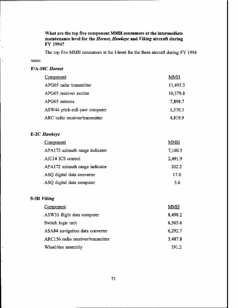
What are the top five component MMH consumers at the intermediate maintenance level for the Hornet, Hawkeye and Viking aircraft during FY 1994?
The top five MMH consumers at the I-level for the three aircraft during FY 1994
were:
F/A-18C Hornet
Component MMH
APG65 radar transmitter 11,493.5
APG65 receiver exciter 10,579.8
APG65 antenna 7,898.7
ASW44 pitch-roll-yaw computer 5,570.3
ARC radio receiver/transmitter 4,819.9
E-2C Hawkeye
Component
APA 172 azimuth range indicator
AIC14 ICS control
APA 172 azimuth range indicator
ASQ digital data converter
ASQ digital data computer
MMH
7,160.5
2,491.9
202.2
17.0
3.6
S-3B Viking
Component
ASW33 flight data computer
Switch logic unit
ASA84 navigation data converter
ARC 156 radio receiver/transmitter
Wheel/tire assembly
MMH
8,498.2
6,565.6
6,292.7
5,487.8
191.2
71

What are the direct labor MMH costs, using conventional fault isola- tion methods to identify failed components, for the three aircraft during FY 1994?
For Hornet maintenance at the organizational and intermediate levels, the total cost
was $1,124,499.33 for the top five component MMH consumers. The primary cost
drivers occurred at the I-level, which included the weapons control system components
(APG65 radar transmitter, APG65 receiver exciter, APG65 antenna). These three
components accounted for approximately 62 percent of the total MMH cost. When the
authors factored in the ASW44 pitch-roll-yaw computer and radio receiver/transmitter, the
I-level accounted for 83 percent of the total direct MMH labor cost.
The Hawkeye's total direct labor MMH cost was $483,465.12 for the top five
consumers at the O- and I-levels. Organizational level MMH costs accounted for
approximately 53 percent of the total cost. The variable pitch propeller was the major O-
level cost driver. It accounted for 23 percent of the total direct labor MMH cost.
Forty-seven percent of the Hawkeye 's total direct labor MMH cost was accumu-
lated at the I-level. The azimuth range indicator (WUC 726J2) was the number one cost
driver. It accounted for 34 percent of the total cost.
The total direct labor MMH cost was $821,025.72 for the Viking's top five MMH
consumers at the O- and I-levels. The organizational maintenance level accounted for 24
percent of the total cost. The ASW33 flight data computer was the number one O-level
cost driver at $462,543.43.
The intermediate maintenance level accounted for 74 percent of the total cost. The
ASW33 flight data computer again accounted for $197,073.26 or 24 percent of the total
cost. The switch logic unit was the second leading cost driver at a cost of $152,256.26
for FY 1994. This was followed by the navigation data converter at a cost of
$145,927.71.
72

B. CONCLUSIONS
From the research completed, the authors have determined it is possible to develop
an empirical model to derive potential direct labor MMH cost savings from expert
systems. The model is flexible and easily modified to determine MMH cost savings for
various type/model/series of aircraft and repair facilities.
The potential benefits of expert systems include reduced MMHs through more
efficient and effective fault isolation. Reduced fault isolation also serves to reduce the
backlog of awaiting maintenance discrepancies. Another benefit is improved operational
readiness by returning systems to ready status sooner through reduced fault isolation time.
The primary MMH consumers for all three aircraft investigated were based on the
top five component direct labor MMH consumers. For the Hornet the primary cost driver
consisted of the APG65 weapons control system, accounting for 62 percent of the total
MMH cost at the O- and I- levels. The Hawkeye's primary MMH consumer at the O-
level was the variable pitch propeller, accounting for 53 percent of the total cost. The
azimuth range indicator was the primary cost driver for the Hawkeye at the I-level,
accounting for 34 percent of the direct labor consumed. The ASW33 was the Viking's
primary cost driver at the O- and I- levels, accounting for over 80 percent of the total O-
and I- level maintenance costs for the top five components.
C. LESSONS LEARNED
This research uncovered several areas that may prove advantageous for further
investigation. The authors originally started in the general direction of identifying the cost
drivers for several aircraft. The potential application areas for using expert systems was
to be made. Determining which area would provide the most meaningful data and
specific information, while weeding out areas beyond the scope and time constraints of
the thesis, proved to be a major learning experience.
The following areas may provide assistance for those pursuing further investigation
into the application of expert systems in the field of Naval aviation maintenance.
73

1. NALDA
Currently, on line access to the NALDA data base is not available at the Naval
Postgraduate School (NPS). Such access would be very valuable in reducing the turn
around time required to obtain aircraft maintenance data. The scope of this thesis had to
be significantly reduced because the turn around time associated with data gathering was
extensive. The data gathering process involved determining a reliable and valid source
of data, the methods required to extract the data from an extremely large database, and
then processing the data into manageable and meaningful information. Not having direct
access to the NALDA database, the authors were fortunate to find an exceptionally astute
and cooperative contact at AIMD NAS Lemoore. Our point of contact, AZl(AW)
Gilman, possessed the expertise to extract NALDA data, using the NAS Lemoore access
node. We provided the background and purpose of the study and the type of data we
were interested in.
Retrieving NALDA data consisted of submitting a request using a password and
the required NALDA system data access codes. Turn around time took several work days
and resulted in large amounts of raw data. AZl(AW) Gilman would then process the data
into meaningful information necessary to facilitate the thesis effort.
Normal turn around was one or two weeks depending on the amount of data
extracted. The information obtained would then be used to determine the fault isolation
percentages and pertinency rates from field technicians. The typical time to obtain
relevant information from technicians added an additional two to three weeks.
Thankfully, AZl(AW) Gilman unselfishly provided his support.
All in all, gathering data from the NALDA database using the process described
was time consuming and not a very efficient process. A significant reduction in
communications and the time required to get data from the NALDA database would result
if NPS had an on-site access node.
74

2. Logistics Management Decision Support System (LMDSS)
LCDR Mike Kelly of NAMO provided a demonstration of LMDSS capabilities at
NPS in March 1995. Using LMDSS he accessed the NALDA database from NPS
terminals and extracted our required data in only 20 minutes. It had taken us months and
a trip to NAS Lemoore to obtain similar data. This thesis project is not the only one that
has required access to NALDA data. Several other students have completed theses which
were dependent on NALDA data. They also faced similar delays in obtaining information
because of the difficulty in accessing NALDA.
LMDSS access from NPS would: (1) alleviate data retrieval time delays, (2)
reduce thesis travel time, (3) reduce thesis travel costs, and (4) reduce the amount of
assistance solicited from fleet personnel.
LMDSS has only been in existence for two years and is accessible via the Internet.
The advantages of LMDSS is that it is instinctive, has push button features and is user
friendly. It allows the user to access data in a manner similar to a "Windows" graphical
user interface application. Data can be gathered based on aircraft type/model/series. The
results are tabulated into an easily useable form.
LMDSS access requires authorization by NAMO and hands on training. NPS
would have to request such authorization via message or naval letter. For long term
continuity, it is recommended that a computer specialist from NPS attend the three- week
NAMO LMDSS computer course. If available, a significant number of aerospace
maintenance and supply officers would use this resource in their research or course work.
3. Electro-Optical Test Set (EOTS)
NAS Lemoore is considered to have the most successful EOTS repair facility in
the Navy. Over the years, the technical representatives have assimilated a tremendous
amount of heuristic knowledge that is vital in efficiently repairing the Hornet's FLIR
system using the test bench. Based on our trip to NAS Lemoore, we believe the EOTS
bench at the AIMD would be a prime candidate for the development of an expert system.
This knowledge has never been incorporated into the operating procedures and
documentation for the system. If the knowledge was encapsulated into an expert system,
75

the impact would prove exceptionally beneficial to Navy maintenance technicians in the
field.
Another justification for an expert system is that with decreased funding, it is
inevitable that there will be some decrease in the number of NAESU technical
representatives in the years ahead. When such experts leave the Navy, the expertise and
knowledge they have accumulated over decades will leave with them. An expert system
would capture this valuable knowledge.
4. VAST/CASS
With the VAST bench being replaced in late 1995, there is little reason to develop
an expert system if development time and potential return on investment are taken under
consideration. With CASS introduction into the fleet at the end of calendar year 1995,
expert systems technology could find a more applicable avenue for development. CASS
will consist of much newer technology requiring development of a new set of heuristic
data and test programs. This integrated approach between expert systems and CASS is
also the preferred method of incorporation according to a NAVAIRSYSCOM representa-
tive. While it is not evident that an expert system in this area would payoff, it seems that
this would be a primary area for further study and investigation.
5. A-799
Another area for potential further review would be in the area of A-799s. As
mentioned in Chapter II, the term A-799 refers to a specific action taken code. In this
case, an item sent to the next higher level of maintenance. Such items are returned to an
RFI status because the repair facility could not find an associated component defect. In
other words, they are perfectly functional parts.
Because of time and funding constraints we were unable to address this issue in
our research. However, we were able to make an initial investigation into A-799s based
on an entire system's two-digit WUC. A two digit code is a much more encompassing
category, as compared to a five digit WUC for singular components. An entire system
is composed of many components which require repair at different types of maintenance
facilities. For example, a two digit WUC would fall under the category bombing
76
navigation systems or interphone systems. A five digit WUC includes specific
components of the system, such as a navigational data converter or a switch logic unit.
Potential A-799 areas to investigate include the full cost and the net price of a
system component. By investigating these two areas, the current procurement cost,
current repair cost, depot washout factor and carcass loss factor of a component can be
determined. Also, a component surcharge is applied to both the full cost and net price
of a component. Therefore, the authors recommend investigating the component
surcharge issue since the following costs may be revealed: (1) supply operations, (2)
transportation, (3) inventory losses, (4) obsolescence, (5) inflation, and (6) inventory
management.
MMHs expended by military, civilian and contractor personnel and other cost
considerations, such as direct labor MMH costs, indirect costs (e.g., travel costs) and
overhead costs, lend themselves to investigation. Lastly, the impact of A-799s on
operational readiness can be investigated.
Appendix B is a suggested flow chart representation of the A-799 issues discussed.
An in-depth examination of A-799 issues, on a single aircraft system, could easily
encompass an entire single thesis topic. We believe such a study is warranted.
6. NETS/CETS
NETS/CETS man-hours were explored as a potential area in which to reduce costs
by applying expert systems. Unfortunately, the differences between military man-hour
accounting methods compared with civilian man-hour accounting methods could not be
resolved. Military man-hours are accounted for on the VIDS/MAFs, and were accessible
via the NALDA database. The civilian man-hours were broken down into more general
tasking areas.
Due to insufficient time, we were not able to further explore the NETS/CETS
man-hour issues to obtain potential cost saving estimates. This topic could be another
potential thesis for students who endeavor to "crack the code" of compatibility between
military and civilian man-hour accounting systems.
77

D. RECOMMENDATIONS
Based upon research conducted in this thesis, conclusions and lessons learned in
the previous section, the following recommendations are offered:
•
•
•
Recommend future research be conducted to determine the applicability of expert systems to help fault isolate Hornet I-level components. Expert systems appear to be applicable to help maintenance technicians fault isolate the Hornet's APG65 radar transmitter, APG65 receiver exciter, and APG65 antenna at the I-level. Based on conversations with technicians, the three APG65 components are categorized as difficult or complex components. This marks the three components as prime candidates to apply expert systems to reduce the fault isolation times, reduce MMHs and save money.
Continue pursuit of LMDSS access from NPS. This could greatly enhance the research capabilities of faculty and students. Current requirements for data retrieval, thesis travel, travel costs, and assistance from fleet personnel could be reduced if LMDSS access is available from NPS.
A prime candidate for the development of an expert system is the EOTS facility at AIMD NAS Lemoore. The technical representatives have assimilated a tremendous amount of heuristic knowledge and data that proves vital for the successful repair of fleet assets. The heuristic data enables NAS Lemoore's EOTS facility to maintain itself as the most successful repair facility of its type in the fleet. Development of an expert system could preserve the vital repair data and prevent its loss in the event that some technical representatives support is further reduced.
The authors recommend further investigation into the implementation of expert systems into the upcoming CASS since the current VAST system is due for replacement late in calendar year 1995. Expert system heuristics must be kept current and updated for eventual incorporation into test programs as part of a continual improvement process. Continued research into the most promising areas of costs/benefits, compatibility and effectiveness could provide a vital core toward the merging of CASS and its test programs with expert systems.
The A-799 issue and the application of expert systems in Naval aviation maintenance field is another area that requires investigation. The adverse impact on operational readiness, associated costs, unnecessary removal/replacement of perfectly functional parts and wasted MMHs are only a few good reasons that this area requires investigation.
78
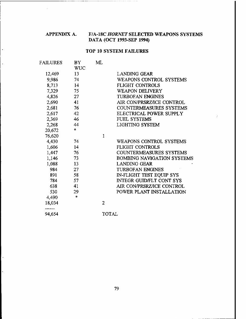
APPENDIX A. F/A-18C HOBNET SELECTED WEAPONS SYSTEMS DATA (OCT 1993-SEP 1994)
TOP 10 SYSTEM FAILURES
JLURES BY wuc
12,469 13 9,986 74 8,713 14 7,329 75 4,826 27 2,690 41 2,681 76 2,617 42 2,369 46 2,268 44
20,672 *
76,620 4,430 74 1,606 14 1,447 76 1,146 73 1,088 13
984 27 891 58 784 57 638 41 530 29
4,490 *
18,034
ML
LANDING GEAR WEAPONS CONTROL SYSTEMS FLIGHT CONTROLS WEAPON DELIVERY TURBOFAN ENGINES AIR CON/PRSRZ/ICE CONTROL COUNTERMEASURES SYSTEMS ELECTRICAL POWER SUPPLY FUEL SYSTEMS LIGHTING SYSTEM
WEAPONS CONTROL SYSTEMS FLIGHT CONTROLS COUNTERMEASURES SYSTEMS BOMBING NAVIGATION SYSTEMS LANDING GEAR TURBOFAN ENGINES IN-FLIGHT TEST EQUIP SYS INTEGR GUID/FLT CONT SYS AIR CON/PRSRZ/ICE CONTROL POWER PLANT INSTALLATION
94,654 TOTAL
79

F/A-18C HORNET SELECTED WEAPONS SYSTEMS DATA (OCT 1993-SEP 1994)
TOP 10 EMT BY SYSTEM
ML FLIGHT CONTROLS LANDING GEAR WEAPONS CONTROL SYSTEMS TURBOFAN ENGINES WEAPON DELIVERY FUEL SYSTEMS AIR COND/PRSRZ/SURFACE ICE CONTROL ELECTRICAL POWER SUPPLY POWER PLANT INSTALLATION COUNTERMEASURES SYSTEMS
WEAPONS CONTROL SYSTEMS FLIGHT CONTROLS COUNTERMEASURES SYSTEMS BOMBING NAVIGATION SYSTEMS ELECTRICAL POWER SUPPLY INTEGRATED GUIDANCE/FLT CONT SYSTEMS LANDING GEAR IN-FLIGHT TEST EQUIPMENT SYSTEMS TURBOFAN ENGINES INTERPHONE SYSTEMS
HOURS BYWUC 23,627.6 14 17,841.5 13 15,594,2 74 9.6^9 7 27 7,e 9.1 75 7,5 8,2 46 6,508.7 41
5,734.1 42 4,893.4 29 3,979.4 76
135,441.6 32,385.7 *
36,790.4 74 12,067.9 14 11,750.4 76 10,934.1 73
5,608.4 42 5,431.8 57
5,425.1 13 4,798.7 58
3,742.3 27 2,935.9 64
22,413.0 *
121,898.0
257,339.6 TOTAL
80

TOP 5 COMPONENT FAILURES
FAILURES BY WUC ML 1,647 75E51 SUU63/A AIRCRAFT PYLON 1,624 751B6 LAU7/A GUIDED MISSILE
LAUNCHER 1,526 13C11 MAIN LANDING GEAR MECH
INSTALLATION 1,442 14211 AILERON INSTALLATION 1,283 754CD BRU32/A ACFT BOMB EJECTOR
RACK 69,098 *
76,620 1 631 742G6 AS3254/APG65 ANTENNA 560 742G1 T1377/APG65 RADAR
TRANSMITTER 513 62X21 RT1250/ARC RADIO RECEIVER
XMTR 500 742G2 R2089/APG65 RADAR RECEIVER
EXCITER 464 57D91 CP1330/ASW44 ROLL-PITCH-
YAW CMPTR 15,366 *
18,034 2
94,654 TOTAL
81

F/A-18C HORNET SELECTED WEAPONS SYSTEMS DATA (OCT 1993-SEP 1994)
TOP 5 ML 1 COMPONENT FAILURES BY MALFUNCTION
FAILURES BY MAL
818 170 215 070
130 425 67 020
wuc
50 160
142 1,422
*
1,008 116
170 070
84 47 36
425 190 020
108 1,399 899 38
*
170 932
34 160
31 020
30 127
129 1,161
*
54 15
170 070
9 9 7
190 425 020
25 119
*
751B6
75E51
754CD
14211
CORRODED PUNCTD/RUPTURED/TORN/ BRKN/CUT/BURST NICKED/CHIPPED STPJPPED/WORN/CHAFED/ FRAYED BROKEN WIRE/DEFEC/ CONTACT/CONNECTION
LAU7/A GUIDED MISSILE LAUNCHER CORRODED PUNCTD/RUPTURED/ TORN/BRKN/CUT/BURST NICKED/CHIPPED CRACKED/CRAZED STRIPPED/WORN/ CHAFED/FRAYED
SUU63/A AIRCRAFT PYLON CORRODED DOES NOT ENGAGE/LOCK/ UNLOCK PROPERLY BROKEN WIRE/DEFEC CONTACT/CONNECTION STRIPPED/WORN/ CHAFED/FRAYED ADJUSTMENT/ALIGNMENT IMPROPER
BRU32/A ACFT BOMB EJECTOR RACK CORRODED PUNCTD/RUPTURED/ TORN/BRKN/CUT/BURST CRACKED/CRAZED NICKED/CHIPPED STRIPPED/WORN/ CHAFED/FRAYED
AILERON INSTALLATION
82

63 170 9 425 6 020
6 070
2 128
14 *
100
CORRODED NICKED/CHIPPED STRIPPED/WORN/ CHAFED/FRAYED PUNCTD/RUPTURED/ TORN/BRKN/CUT/BURST RIGGING/INDEXING INCORRECT
13C11 MAIN LANDING GEAR MECH INSTALLATION
4,201 TOTAL
EMT FOR TOP 5 ML 1 COMPONENT FAILURES
HOURS BYWUC 1,663.1 75E51 1,405.4 751B6
898.6 754CD 317.7 14211 159.3 13C11
SUU63/A AIRCRAFT PYLON LAU7/A GUIDED MISSILE LAUNCHER BRU32/A ACFT BOMB EJECTOR RACK AILERON INSTALLATION MAIN LANDING GEAR MECH INSTALLATION
4,444.1 TOTAL
83

F/A-18C HORNET SELECTED WEAPONS SYSTEMS DATA (OCT 1993-SEP 1994)
MMH FOR VERIFIED ML 1 FAILURES
HOURS 14,324.9 47,839.0 35,641.9
BYWUC 75 14 13
WEAPON DELIVERY FLIGHT CONTROLS LANDING GEAR
97,805.8 TOTAL
MMH FOR TOP 5 ML 1 COMPONENT FAILURES
HOURS 3,082.6
2,445.9
1,761.6
587.0
251.4
BYWUC 75E51 SUU63/A AIRCRAFT
PYLON 751B6 LAU7/A GUIDED MISSILE
LAUNCHER 754CD BRU32/A ACFT BOMB
EJECTOR RACK 14211 AILERON
INSTALLATION 13C11 MAIN LANDING GEAR
MECH INSTALLATION
8,128.5 TOTAL
84
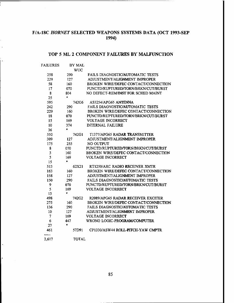
F/A-18C HORNET SELECTED WEAPONS SYSTEMS DATA (OCT 1993-SEP 1994)
TOP 5 ML 2 COMPONENT FAILURES BY MALFUNCTION
FAILURES BY MAL WUC
258 290 229 127 58 160 17 070 8 804 25 *
595 742G6 242 290 229 160 18 070 15 169 10 374 36 *
550 742G1 309 127 175 255 8 070 3 160 3 169 15 *
513 62X21 163 160 158 127 150 290 9 070 5 169 13 *
498 742G2 275 160 136 290 10 127 7 169 6 447 27 *
461 57D91
FAILS DIAGNOSTIC/AUTOMATIC TESTS ADJUSTMENT/ALIGNMENT IMPROPER BROKEN WIRE/DEFEC CONTACT/CONNECTION PUNCTD/RUPTUREDnrORN/BRKN/CUT/BURST NO DEFECT-REM/INST FOR SCHED MAINT
AS3254/APG65 ANTENNA FAILS DIAGNOSTIC/AUTOMATIC TESTS BROKEN WIRE/DEFEC CONTACT/CONNECTION PUNCTD/RUPTURED/TORN/BRKN/CUT/BURST VOLTAGE INCORRECT INTERNAL FAILURE
T1377/APG65 RADAR TRANSMITTER ADJUSTMENT/ALIGNMENT IMPROPER NO OUTPUT
PUNCTD/RUPTURED/TORN/BRKN/CUT/BURST BROKEN WIRE/DEFEC CONTACT/CONNECTION VOLTAGE INCORRECT
RT1250/ARC RADIO RECEIVER XMTR BROKEN WIRE/DEFEC CONTACT/CONNECTION ADJUSTMENT/ALIGNMENT IMPROPER FAILS DIAGNOSTIC/AUTOMATIC TESTS
PUNCTD/RUPTURED/TORN/BRKN/CUT/BURST VOLTAGE INCORRECT
R2089/APG65 RADAR RECEIVER EXCITER BROKEN WIRE/DEFEC CONTACT/CONNECTION FAILS DIAGNOSTIC/AUTOMATIC TESTS ADJUSTMENT/ALIGNMENT IMPROPER VOLTAGE INCORRECT WRONG LOGIC-PROGRAM/COMPUTER
CP1330/ASW44 ROLL-PITCH-YAW CMPTR
2,617 TOTAL
85

EMT FOR TOP 5 ML 2 COMPONENT FAILURES
HOURS BY WUC 5.474.8 742G1 T1377/APG65 RADAR TRANSMITTER 5.300.9 742G2 R2089/APG65 RADAR RECEIVER EXCITER 3,833.1 742G6 AS3254/APG65 ANTENNA 3,051.3 57D91 CP1330/ASW44 ROLL-PITCH-YAW CMPTR 2,483.9 62X21 RT1250/ARC RADIO RECEIVER XMTR
20,144.0 TOTAL
86

F/A-18C HOBNET SELECTED WEAPONS SYSTEMS DATA (OCT 1993-SEP 1994)
HOURS 69,209.2 4,924.5 9,669.9
MMH FOR VERD7D2D ML 2 FAILURES
BYWUC 74 WEAPONS CONTROL SYSTEMS 62 VHF COMM SYSTEMS 57 INTEGRATED GUIDANCE/FLT CONT SYSTEMS
83,803.6 TOTAL
MMH FOR TOP 5 ML 2 COMPONENT FAILURES
HOURS BY 11,493.5 742G1 10,579.8 742G2 7,898.7 742G6 5,570.3 57D91 4,819.9 62X21
40,362.2
T1377/APG65 RADAR TRANSMITTER R2089/APG65 RADAR RECEIVER EXCITER AS3254/APG65 ANTENNA CP1330/ASW44 ROLL-PITCH-YAW CMPTR RT1250/ARC RADIO RECEIVER XMTR
TOTAL
TOP 10 NMCS COMPONENTS
HOURS 103,943.2 77,267.9 74,650.0 66,991.5 56,427.8 46,520.7 46,401.9 36,409.5 35,065.7 34,937.1
1,517,638.7
2,096,254.0
BY BEST- 27400 14513 742G6 14211 14612 742G1 14312 57D91 14412 58X17
TOTAL
WUC F404-GE-ENGINE LEADING EDGE FLAP DRIVE INSTL AS3254/APG65 ANTENNA AILERON INSTALLATION TRAILING EDGE FLAP CONTROL T1377/APG65 RADAR TRANSMITTER STABILIZER CONTROL INSTALLATION CP1330/ASW44 ROLL-PITCH-YAW CMPTR RUDDER CONTROL ID2389/A INTEG FUEL-ENGINE IND
87
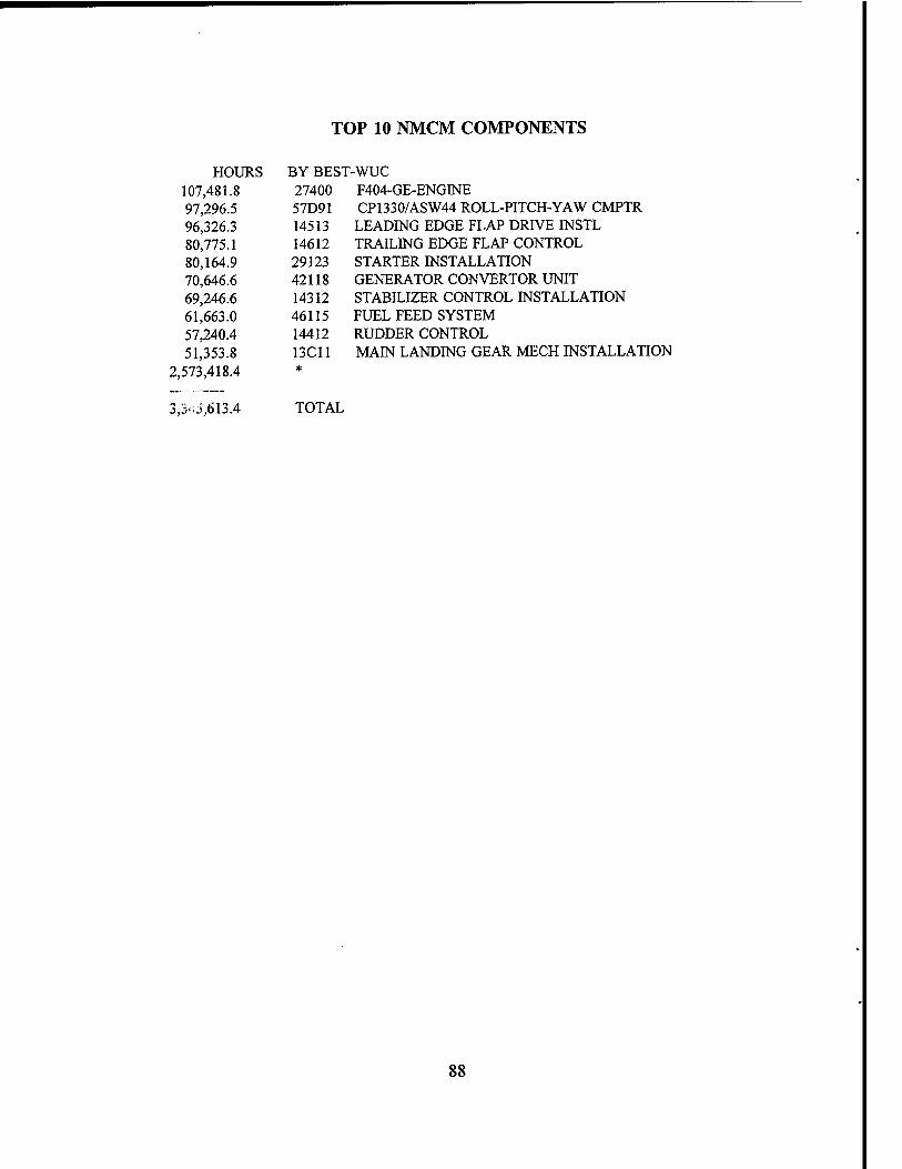
TOP 10 NMCM COMPONENTS
HOURS BY BEST- 107,481.8 27400 97,296.5 57D91 96,326.3 14513 80,775.1 14612 80,164.9 29123 70,646.6 42118 69,246.6 14312 61,663.0 46115 57,240.4 14412 51,353.8 13C11
2,573,418.4 *
-wuc F404-GE-ENGINE CP1330/ASW44 ROLL-PITCH-YAW CMPTR LEADING EDGE FLAP DRIVE INSTL TRAILING EDGE FLAP CONTROL STARTER INSTALLATION GENERATOR CONVERTOR UNIT STABILIZER CONTROL INSTALLATION FUEL FEED SYSTEM RUDDER CONTROL MAIN LANDING GEAR MECH INSTALLATION
3,3^5,613.4 TOTAL
88

F/A-18C HORNET SELECTED WEAPONS SYSTEMS DATA (OCT 1993-SEP 1994)
TOP 5 A799 MMH/SYSTEMS
HOURS BY WUC ML
6.490.7 74 WEAPONS CONTROL SYSTEMS 2.092.5 57 INTEGRATED GUIDANCE/FLT CONT SYSTEMS 2.040.6 14 FLIGHT CONTROLS 1.749.3 27 TURBOFAN ENGINES 1.710.5 13 LANDING GEAR
11,166.4 * 25,250.0 1 8,303.0 74 WEAPONS CONTROL SYSTEMS 3.239.6 73 BOMBING NAVIGATION SYSTEMS 2.063.8 57 INTEGRATED GUIDANCE/FLT CONT SYSTEMS 1,489.6 58 IN-FLIGHT TEST EQUIPMENT SYSTEMS 1,014.6 75 WEAPON DELIVERY 8.002.4 *
24,113.0 2
49,363.0 TOTAL
89

E-2C HAWKEYE SELECTED WEAPONS SYSTEMS DATA (OCT 1993-SEP 1994)
TOP 10 SYSTEM FAILURES
FAILURES BY WUC ML
6,888 72 RADAR NAVIGATION SYSTEMS 4,427 44 LIGHTING SYSTEMS 3,756 29 POWER PLANT INSTALLATION 3,368 13 ALIGHTING/LAUNCHING SYSTEM 2,981 14 DIRECTIONAL FLT CONTROLS/LIFT SYSTEM 2,703 41 ENVIRONMENTAL CONTROLS/PNEUMATIC SYS 2,681 42 ELEC PWR SPLY/DISTRIBUTION/LTG SYS 2,106 32 HYDRAULIC PROPELLERS 1,788 12 FURNISHINGS/COMPARTMENTS 1,724 22 TURBOSHAFT ENGINES
17,023 * 49,445 1 4,167 72 RADAR NAVIGATION SYSTEMS
846 73 BOMBING NAVIGATION SYSTEMS 789 56 FLIGHT REFERENCE SYSTEMS 463 61 HF COMMUNICATIONS SYSTEMS 446 13 ALIGHTING/LAUNCHING SYSTEMS 443 64 INTERPHONE SYSTEMS 437 29 POWER PLANT INSTALLATION 427 51 INSTRUMENTATION SYSTEMS 414 41 ENVIRONMENTAL CONTROLS/PNEUMATIC SYS 392 22 TURBOSHAFT ENGINES
3,091 * 11,915 2
61,360 TOTAL
90

E-2C HAWKEYE SELECTED WEAPONS SYSTEMS DATA (OCT 1993-SEP 1994)
TOP 10 EMT BY SYSTEM
RADAR NAVIGATION SYSTEMS DIRECTIONAL FLT CONTROLS/LIFT SYSTEM POWER PLANT INSTALLATION ELEC PWR SPLY/DISTRIBUTION/LTG SYSTEM HYDRAULIC PROPELLERS ENVIRONMENTAL CONTROLS/PNEUMATIC SYS ALIGHTING/LAUNCHING SYSTEM TURBOSHAFT ENGINES LIGHTING SYSTEMS FLIGHT REFERENCE SYSTEMS
RADAR NAVIGATION SYSTEMS BOMBING NAVIGATION SYSTEMS HF COMMUNICATIONS SYSTEMS COUNTERMEASURES SYSTEMS FLIGHT REFERENCE SYSTEMS POWER PLANT INSTALLATION IFF SYSTEMS INSTRUMENTATION SYSTEMS INTERPHONE SYSTEMS INTEGRATED GUIDANCE/FLT CONT SYSTEMS)
HOURS BY WUC ML
18,750.3 72 10,110.1 14 8,431.2 29 8,093.3 42 7,898.4 32 7,704.0 41 6,876.3 13 5,251.3 22 4,837.0 44 3,615.2 56
33,491.0 *
115,058.1 1 35,707.0 72 11,637.5 73 4,117.8 61 3,785.2 76 3,091.4 56 3,048.5 29 2,576.2 65 2,476.1 51 2,442.8 64 2,432.0 57 17,311.0 *
88,625.5 2
203,683.6 TOT.A
91

TOP 5 COMPONENT FAILURES
FAILURES
1,331 901 645 621 599
45,348 49,445
524 294 291 273 263
10,270 11,915
61,360
BYWUC ML
4422K UTILITY LIGHT 32512 VARIABLE PITCH PROPELLER 14121 RUDDER 29E10 POWER PLANT SYSTEM INSTL/ENGINE ASSY 32513 PROPELLER CONTROL ASSEMBLY
726J4 IP 1040/APA172 AZ RANGE IND (CONTD) 726J2 IP 1040/APA172 AZ RANGE INDICATOR 728E1 CP1084/ASQ DGTL DATA CMPTR 46A1 728E2 CV2868/ASQ DIGITAL DATA CONV 46A2 64184 C2645/AIC14 ICS CONTROL
TOTAL
92

E-2C HAWKEYE SELECTED WEAPONS SYSTEMS DATA (OCT 1993-SEP 1994)
TOP 5 ML 1 COMPONENT FAILURES BY MALFUNCTION
FAILURES BY MAL WUC
1,060 080 100 160 76 070 31 170 13 374 51 *
1,331 4422K 241 170 70 127 70 306 68 020 36 381 136 *
621 29E10 67 170 62 020 44 117 44 127 40 458 140 *
397 32512 95 170 40 020 32 190 32 425 19 070 58 *
276 14121 14 170 8 381 5 070 4 037 3 127 15 *
49 32513
BURNED OUT (LIGHT BULBS/FUSES) BROKEN WIRE/DEFECTIVE/CONNECTION PUNCTD/RUPTURED/TORN/BRKN/CUT/BURST CORRODED INTERNAL FAILURE
UTILITY LIGHT CORRODED ADJUSTMENT/ALIGNMENT IMPROPER CONTAMINATION (NON-METALLIC) STRIPPED/WORN/CHAFED/FRAYED LEAKING-INTERNAL/EXTERNAL
POWER PLANT SYS INSTL/ENGINE ASSY CORRODED STRIPPED/WORN/CHAFED/FRAYED DETERIORATED/ERODED ADJUSTMENT/ALIGNMENT IMPROPER OUT OF BALANCE
VARIABLE PITCH PROPELLER CORRODED STRIPPED/WORN/CHAFED/FRAYED CRACKED/CRAZED NICKED/CHIPPED PUNCTD/RUPTURED/TORN/BRKN/CUT/BURST
RUDDER CORRODED LEAKING-INTERNAL/EXTERNAL PUNCTD/RUPTURED/TORN/BRKN/CUT/BURST FLUCTUATES/OSCILLATES ADJUSTMENT/ALIGNMENT IMPROPER
PROPELLER CONTROL ASSEMBLY
2,674 TOTAL
93

EMT FOR TOP 5 ML 1 COMPONENT FAILURES
HOURS BY WUC 1,939.4 32512 VARIABLE PITCH PROPELLER 1,186.4 29E10 POWER PLANT SYSTEM INSTL/ENGINE ASSY L083.0 4422K UTILITY LIGHT
706.4 14121 RUDDER 206.6 32513 PROPELLER CONTROL ASSEMBLY
5,121.8 TOTAL
94

E-2C HAWKEYE SELECTED WEAPONS SYSTEMS DATA (OCT 1993-SEP 1994)
HOURS 18,502.7 16,748.9 7,644.8
20,030.8
MMH FOR VERIFIED ML 1 FAILURES
BYWUC 32 HYDRAULIC PROPELLERS 29 POWER PLANT INSTALLATION 44 LIGHTING SYSTEMS 14 DIRECTIONAL FLT CONTROLS/LIFT SYSTEM
62,927.2 TOTAL
MMH FOR TOP 5 ML 1 COMPONENT FAILURES
HOURS BYWUC 4,808.3 32512 VARIABLE PITCH PROPELLER 2,716.0 29E10 POWER PLANT SYSTEM INSTL/ENGINE ASSY 1,639.1 4422K UTILITY LIGHT 1,298.7 14121 RUDDER
510.7 32513 PROPELLER CONTROL ASSEMBLY
10,972.8 TOTAL
TOP 5 ML 2 COMPONENT FAILURES BY MALFUNCTION
FAILURES BY MAL WUC
102 127 85 160 75 290 15 070 4 374
13 *
294 726J2 77 255 63 070 57 160 31 127 10 374 25 *
263 64184 15 070 12 160 7 127 2 135 2 290 6 *
44 726J4
ADJUSTMENT/ALIGNMENT IMPROPER BROKEN WIRE/DEFEC/CONTACT/CONNECTION FAILS DIAGNOSTIC/AUTOMATIC TESTS PUNCTD/RUPTURED/TORN/BRKN/CUT/BURST INTERNAL FAILURE
IP1040/APA172 AZ RANGE INDICATOR NO OUTPUT PUNCTD/RUPTURED/TORN/BRKN/CUT/BURST BROKEN WIRE/DEFEC CONTACT/CONNECTION ADJUSTMENT/ALIGNMENT IMPROPER INTERNAL FAILURE
C2645/AIC14 ICS CONTROL PUNCTD/RUPTURED/TORN/BRKN/CUT/BURST BROKEN WIRE/DEFEC CONTACT/CONNECTION ADJUSTMENT/ALIGNMENT IMPROPER STRUCK/BINDING/JAMMED FAILS DIAGNOSTIC/AUTOMATIC TESTS
IP1040/APA172 AZ RANGE IND (CONTD)
95
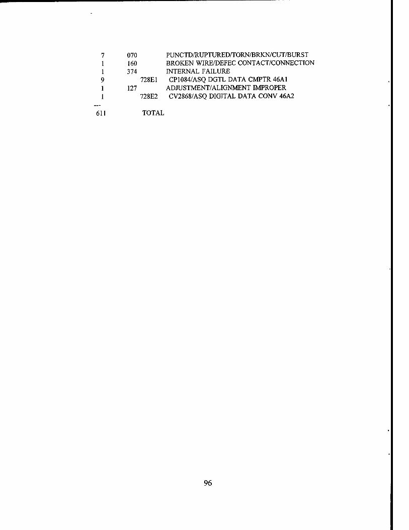
7 070 1 160 1 374 9 1 127 1
PUNCTD/RUPTURED/TORN/BRKN/CUT/BURST BROKEN WIRE/DEFEC CONTACT/CONNECTION INTERNAL FAILURE
728E1 CP1084/ASQ DGTL DATA CMPTR 46A1 ADJUSTMENT/ALIGNMENT IMPROPER
728E2 CV2868/ASQ DIGITAL DATA CONV 46A2
611 TOTAL
96

E-2C HAWKEYE SELECTED WEAPONS SYSTEMS DATA (OCT 1993-SEP 1994)
EMT FOR TOP 5 ML 2 COMPONENT FAILURES
HOURS BY1
3,941.1 726J2 1,437.6 64184
157.2 726J4 17.0 728E2 1.8 728E1
5,554.7
IP1040/APA172 AZ RANGE INDICATOR C2645/AIC14 ICS CONTROL IP1040/APA172 AZ RANGE IND (CONTD) CV2868/ASQ DIGITAL DATA CONV 46A2 CP1084/ASQ DGTL DATA CMPTR 46A1
TOTAL
MMH FOR VERIFIED ML 2 FAILURES
HOURS 64,381.5 4,256.8
BYWUC 72 RADAR NAVIGATION SYSTEMS 65 INTERPHONE SYSTEMS
68,638.3 TOTAL
MMH FOR TOP 5 ML 2 COMPONENT FAILURES
HOURS BYWUC 7,160.5 2,491.9
202.2 17.0 3.6
9,875.2
726J2 64184 726J4 728E2 728E1
TOTAL
IP1040/APA172 AZ RANGE INDICATOR C2645/AIC14 ICS CONTROL IP1040/APA172 AZ RANGE IND (CONTD) CV2868/ASQ DIGITAL DATA CONV 46A2 CP1084/ASQ DGTL DATA CMPTR 46A1
TOP 10 NMCS COMPONENTS
HOURS BY BEST- 21,144.1 1441B 20,922.8 14121 14,750.0 728E1 14,258.1 1451A 11,841.8 62X2K 11,244.0 728E2 9,692.8 726DW 8,435.6 32513 7,789.4 726T3 7,588.7 14521
633,731.1 *
-WUC FEEL SPRING PUSHROD RUDDER CP1084/ASQ DGTL DATA CMPTR 46AI BUNGEE F1556 BANDPASS FILTER
CV2868/ASQ DIGITAL DATA CONV 46A2 AM6412/APS120 RF AMPLIFIER
PROPELLER CONTROL ASSEMBLY O1720/APS125 PULSE GENERATOR ELEVATOR TANDEM ACTUATOR
761,398.4 TOTAL
97

E-2C HAWKEYE SELECTED WEAPONS SYSTEMS DATA (OCT 1993-SEP 1994)
TOP 10 NMCM COMPONENTS
HOURS BY BEST 120,731.2 14121 57,421.8 223D1 45,216.9 29E11 44,834.4 32513 38,775.2 29E1B 37,869.1 14141 36,242.6 14131 27,804.1 45111 25,705.3 14521 23,549.5 4512Q
1,553,793.4 *
2,011,943.5 TOTAL
-wuc RUDDER FUEL SYSTEM ASSEMBLY ENGINE ACCESSORIES INSTALLATION PROPELLER CONTROL ASSEMBLY ENGINE OIL COOLER INSTALLATION
LANDING FLAPS ELEVATOR VARIABLE DISPLACEMENT PUMP 3000 P ELEVATOR TANDEM ACTUATOR HYDRAULIC HOSE/TUBING
TOP 5 A799 MMH/SYSTEMS
HOURS
2,415.8 1,274.4
727.4 724.8 637.6
6,048.7 11,828.7 5,129.3 1,960.4
789.7 674.8 669.2
4,261.2 13.484.6
BY WUC ML
72 RADAR NAVIGATION SYSTEMS 42 ELEC PWR SPLY/DISTR/LTG SYSTEMS 14 DIRECTIONAL FLT CONT/LIFT SYSTEM 41 ENVIRON CONTROLS/PNEUMATIC SYS 29 POWER PLANT INSTALLATION
72 RADAR NAVIGATION SYSTEMS 73 BOMBING NAVIGATION SYSTEMS 61 HF COMM SYSTEMS 56 FLIGHT REFERENCE SYSTEMS 64 INTERPHONE SYSTEMS
25,313.3 TOTAL
98

S-3B VIKING SELECTED WEAPONS SYSTEMS DATA (OCT 1993-SEP 1994)
TOP 10 SYSTEM FAILURES
COUNT BY WUC ML
8,762 73 BOMBING NAVIGATION SYSTEMS 6,988 14 FLIGHT CONTROLS 6,978 13 LANDING GEAR 6,659 42 ELECTRICAL POWER SYSTEM 4,926 29 POWER PLANT INSTALLATION 4,248 44 LIGHTING SYSTEM 3,417 27 TURBOFAN ENGINES 2,867 41 AIR CON/PRSRZ/ICE CONTROL 2,720 72 RADAR NAVIGATION SYSTEMS 2,691 64 INTERPHONE SYSTEMS
20,872 * 71,128 1 5,098 73 BOMBING NAVIGATION SYSTEMS 1,247 13 LANDING GEAR 1,126 64 INTERPHONE SYSTEMS 1,124 72 RADAR NAVIGATION SYSTEMS 1,074 14 FLIGHT CONTROLS
967 57 INTGRTD GDNCE/FLT CONT SYS 820 71 RADIO NAVIGATION SYSTEMS 743 29 POWER PLANT INSTALLATION 627 42 ELECTRICAL POWER SYSTEM 593 27 TURBOFAN ENGINES
5,237 * 18,656 2
89,784 TOTAL
99

TOP 10 EMT BY SYSTEM
SUM BY WUC ML
19,262.7 14 FLIGHT CONTROLS 16.094.7 73 BOMBING NAVIGATION SYSTEMS 13.779.8 42 ELECTRICAL POWER SYSTEM 11.031.2 13 LANDING GEAR 7,979.2 29 POWER PLANT INSTALLATION 7,854.6 27 TURBOFAN ENGINES 5,083.8 41 AIR CONDITIONING/PRSRZ/ICE CONTROL 4,949.0 44 LIGHTING SYSTEM 4.573.5 72 RADAR NAVIGATION SYSTEMS 4,096.0 46 FUEL SYSTEM
33,270.8 * 127.975.3 1 40,708.1 73 BOMBING NAVIGATION SYSTEMS 9.086.6 64 INTERPHONE SYSTEMS 8,691.8 72 RADAR NAVIGATION SYSTEMS 7,717.5 57 INTEGRATED GUIDANCE/FLT CONT SYSTEMS 5.831.8 77 PHOTOGRAPHIC/RECONNAISSANCE SYSTEMS 5.639.9 71 RADIO NAVIGATION SYSTEMS 4,799.8 13 LANDING GEAR 4.636.7 14 FLIGHT CONTROLS 4,407.2 65 IFF SYSTEMS 4,143.4 63 UHF COMMUNICATIONS
24.825.3 * 120,488.1 2
248.463.4 TOTAL
TOP 5 COMPONENT FAILURES
COUNT BY WUC ML
1,492 29Q4H ENG PYLON INST/ASSY 1,180 57367 CP1074/ASW33 FLT DATA
COMPUTER 947 64351 LS601/AI INTERCOMMUNICA-
TION STATION 914 64354 CV3048/AICONV
INTERCONNECT BOX 810 754BQ BRU14 BOMB RACK
ASSEMBLY 65,785 * 71,128 1
100

709 13A6K WHL/TIRE ASSY/BK ASSY/SHTL Y/DUAL FL
492 57367 CP1074/ASW33 FLT DATA COMPUTER
452 73B62 CV2745/ASA84 NAV DATA CONVERTER
450 63271 RT1017/ARC156 RADIO RCVR-XMTR
430 64354 CV3048/AI CONV INTERCONNECT BOX
16,123 *
18,656 2
89,784 TOTAL
TOP 5 ML 1 COMPONENT FAILURES BY MALFUNCTION
COUNT BY MAL WUC
559 160 297 374 128 127 55 070 29 255 87 *
1,155 57367 310 160 242 080 80 255 77 374 44 070 186 *
939 64351 470 160 138 255 82 290 79 374 44 170 97 *
910 64354 620 170 68 160 26 070 22 127 9 020
37 *
782 754BQ
BROKEN WIRE/DEFEC CONTACT/CONNECTION INTERNAL FAILURE ADJUSTMENT/ALIGNMENT IMPROPER PUNC/RUPTURED/TORN/BRKN/CUT/BURST NO OUTPUT
CP1074/ASW33 FLT DATA COMPUTER BROKEN WIRE/DEFEC CONTACT/CONNECTION BURNED OUT (LIGHT BULBS/FUSES) NO OUTPUT INTERNAL FAILURE PUNC/RUPTURED/TORN/BRKN/CUT/BURST
LS601/AI INTERCOMMUNICATION STATION BROKEN WIRE/DEFEC CONTACT/CONNECTION NO OUTPUT FAILS DIAGNOSTIC/AUTOMATIC TESTS INTERNAL FAILURE CORRODED
CV3048/AI CONV INTERCONNECT BOX CORRODED BROKEN WIRE/DEFEC CONTACT/CONNECTION PUNC/RUPTURED/TORN/BRKN/CUT/BURST ADJUSTMENT/ALIGNMENT IMPROPER STRIPPED/WORN/CHAFED/FRAYED
BRU14 BOMB RACK ASSEMBLY
101

CORRODED PUNC/RUPTURED/TORN/BRKN/CUT/BURST PEELED/BLISTERED STRIPPED/WORN/CHAFED/FRAYED CRACKED/CRAZED
29Q4H ENGINE WING PYLON INSTALLATION/ASSY
3,980 TOTAL
EMT FOR TOP 5 ML 1 COMPONENT FAILURES
113 170 18 070 17 429 8 020 8 190
30 *
194
SUM BY^ 1,582.4 57367 1,401.5 64354 1,132.3 64351
706.3 754BQ 301.3 29Q4H
5,123.8
CP1074/ASW33 FLT DATA COMPUTER CV3048/AI CONV INTERCONNECT BOX LS601/AI INTERCOMMUNICATION STATION BRU14 BOMB RACK ASSEMBLY ENGINE WING PYLON INSTALLATION/ASSY
TOTAL
MMH FOR VERIFIED ML 1 FAILURES
SUM 5,781.1 6,227.6 2,259.7
14,368.4
BY WUC 57 64 75
TOTAL
INTEGRATED GUIDANCE/FLT CONT SYSTEMS INTERPHONE SYSTEMS WEAPON DELIVERY
MMH FOR TOP 5 ML 1 COMPONENT FAILURES
SUM BY^ 2,697.0 57367 2,489.4 64354 1,879.4 64351
877.2 754BQ 425.8 29Q4H
8,368.8 TOTAL
CP1074/ASW33 FLT DATA COMPUTER CV3048/AI CONV INTERCONNECT BOX LS601/AI INTERCOMMUNICATION STATION BRU14 BOMB RACK ASSEMBLY ENGINE WING PYLON INSTALLATION/ASSY
102

TOP 5 ML 2 COMPONENT FAILURES BY MALFUNCTION
COUNT BY MAL WUC
283 160 151 290 35 070 4 374 3 127 10 *
486 57367 272 160 141 290 15 070 14 127 2 374 7 *
451 73B62 149 127 119 290 116 160 33 070 12 170 18 *
447 63271 240 160 102 290 43 127 27 070 10 374 6 *
428 64354 6 572 4 020 4 781 3 070 3 571 9 *
29 13A6K
BROKEN WIRE/DEFEC CONTACT/CONNECTION FAILS DIAGNOSTIC/AUTOMATIC TESTS PUNC/RUPTURED/TORN/BROKEN/CUT/BURST INTERNAL FAILURE ADJUSTMENT/ALIGNMENT IMPROPER
CP1074/ASW33 FLT DATA COMPUTER BROKEN WIRE/DEFEC CONTACT/CONNECTION FAILS DIAGNOSTIC/AUTOMATIC TESTS PUNCT/RUPTURED/TORN/BROKEN/CUT/BURST ADJUSTMENT/ALIGNMENT IMPROPER INTERNAL FAILURE
CV2745/ASA84 NAV DATA CONVERTER ADJUSTMENT/ALIGNMENT IMPROPER FAILS DIAGNOSTIC/AUTOMATIC TESTS BROKEN WIRE/DEFEC CONTACT/CONNECTION PUNCT/RUPTURED/TORN/BROKEN/CUT/BURST CORRODED
RT1017/ARC156 RADIO RCVR-XMTR BROKEN WIRE/DEFEC CONTACT/CONNECTION FAILS DIAGNOSTIC/AUTOMATIC TESTS ADJUSTMENT/ALIGNMENT IMPROPER PUNCT/RUPTURED/TORN/BROKEN/CUT/BURST INTERNAL FAILURE
CV3048/AI CONV INTERCONNECT BOX EDDY-CURRENT INSPECTION STRIPPEDAVORN/CHAFED/FRAYED TIRE LEAKAGE EXCESSIVE OR BLOWOUT PUNCT/RUPTURED/TORN/BROKEN/CUT/BURST MAGNETIC PARTICLE INSPECTION
WHL/TIRE ASSY/BK ASSY/SHTLY/DUAL FL
1,841 TOTAL
103
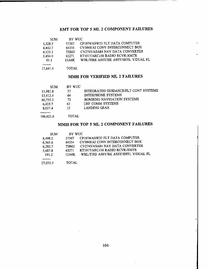
EMT FOR TOP 5 ML 2 COMPONENT FAILURES
SUM BY WUC 5,528.3 57367 CP1074/ASW33 FLT DATA COMPUTER 4,442.7 64354 CV3048/AI CONV INTERCONNECT BOX 4,125.3 73B62 CV2745/ASA84 NAV DATA CONVERTER 3,454.0 63271 RT1017/ARC156 RADIO RCVR-XMTR
91.1 13A6K WHL/TIRE ASSY/BK ASSY/SHTL Y/DUAL FL
17,641.4 TOTAL
MMH FOR VERIFIED ML 2 FAILURES
SUM BY WUC 11,981.8 57 INTEGRATED GUIDANCE/FLT CONT SYSTEMS 13,413.4 64 INTERPHONE SYSTEMS 66,753.3 73 BOMBING NAVIGATION SYSTEMS 6,435.7 63 UHF COMM SYSTEMS 8,037.4 13 LANDING GEAR
106,621.6 TOTAL
MMH FOR TOP 5 ML 2 COMPONENT FAILURES
SUM BY WUC 8,498.2 57367 CP1074/ASW33 FLT DATA COMPUTER 6.565.6 64354 CV3048/AI CONV INTERCONNECT BOX 6.292.7 73B62 CV2745/ASA84 NAV DATA CONVERTER 5^487.8 63271 RT1017/ARC156 RADIO RCVR-XMTR
191.2 13A6K WHL/TIRE ASSY/BK ASSY/SHTL Y/DUAL FL
27,035.5 TOTAL
104
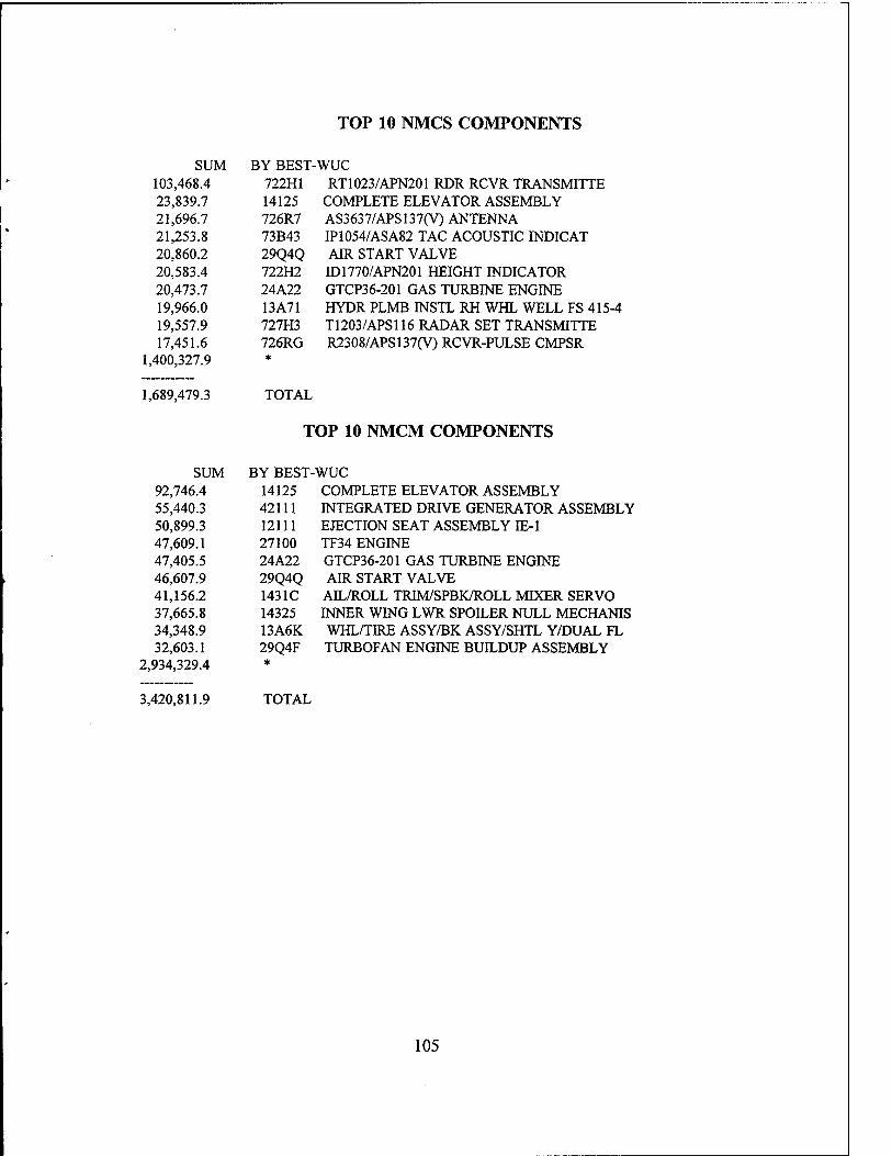
TOP 10 NMCS COMPONENTS
SUM BY BEST- 103,468.4 722H1 23,839.7 14125 21,696.7 726R7 21,253.8 73B43 20,860.2 29Q4Q 20,583.4 722H2 20,473.7 24A22 19,966.0 13A71 19,557.9 727H3 17,451.6 726RG
1,400,327.9 *
1,689,479.3 TOTAL
■wuc RT1023/APN201 RDR RCVR TRANSMITTE
COMPLETE ELEVATOR ASSEMBLY AS3637/APS137(V) ANTENNA IP1054/ASA82 TAC ACOUSTIC INDICAT AIR START VALVE ID1770/APN201 HEIGHT INDICATOR GTCP36-201 GAS TURBINE ENGINE HYDR PLMB INSTL RH WHL WELL FS 415-4 T1203/APS116 RADAR SET TRANSMITTE R2308/APS137(V) RCVR-PULSE CMPSR
TOP 10 NMCM COMPONENTS
SUM BY BEST-WUC 92.746.4 14125 COMPLETE ELEVATOR ASSEMBLY 55,440.3 42111 INTEGRATED DRIVE GENERATOR ASSEMBLY 50,899.3 12111 EJECTION SEAT ASSEMBLY IE-1 47.609.1 27100 TF34 ENGINE 47.405.5 24A22 GTCP36-201 GAS TURBINE ENGINE 46,607.9 29Q4Q AIR START VALVE 41.156.2 1431C AEL/ROLL TRIM/SPBK/ROLL MIXER SERVO 37.665.8 14325 INNER WING LWR SPOILER NULL MECHANIS 34.348.9 13A6K WHL/TIRE ASSY/BK ASSY/SHTL Y/DUAL FL 32,603.1 29Q4F TURBOFAN ENGINE BUILDUP ASSEMBLY
2,934,329.4 *
3,420,811.9 TOTAL
105

TOP 5 A799 MMH/SYSTEMS
SUM BY WUC ML
2,636.1 73 BOMBING NAVIGATION SYSTEMS 820.3 14 FLIGHT CONTROLS 648.8 72 RADAR NAVIGATION SYSTEMS 637.9 13 LANDING GEAR 538.1 46 FUEL SYSTEM
5,226.3 *
10,507.5 1 6,274.3 73 BOMBING NAVIGATION SYSTEMS 1,349.4 57 INTEGRATED GUIDANCE/FLT CON 1,273.3 72 RADAR NAVIGATION SYSTEMS 1,193.9 64 INTERPHONE SYSTEMS 1,077.1 71 RADIO NAVIGATION SYSTEMS 6,111.2 *
17,279.2 2
27,786.7 TOTAL
106

APPENDIX B. A-799
Component cost
FUVStandardl cost I
Current procurement cost
j Surcharge
Costs of Supply ops
^ Inventory ** Losses
Transportation
Obsolescence I
Price stabilzationAnflation
Inventory malnt
A-799 considerations
Current repair cost
Depot washout factor Y
Carcass loss factor
!•
CMian tech reps I
Contractor lech reps
Military techs
Direct Costs I
Ovllan, contractor, miitary man-hour
Othercost I considerations I
Indirect costs
I Overhead | costs I
107

108

LIST OF REFERENCES
Bennett, J.L..Building Decision Support Systems. Addison-Wesley, 1983.
Mockler, R.J.. Knowledge-Based Systems for Management Decisions. Prentice- Hall, 1987.
Prerau. D.S..Developing and Managing Expert Systems. Addison-Wesley, 1990.
Powell, S.H., Economic Analysis of the MK 92 Mod 2 Fire Control System Maintenance Advisor Expert System. Master's Thesis, Naval Postgraduate School, Monterey, California, September 1993.
Lischke, M.P., TEAMS: Technical Expert Aircraft Maintenance System. Proceedings of the IEEE 1992 National Aerospace and Electronics Conference, 1992.
Papp, M.L.,Braisted, W.R.,and Taylor, W.R.. A Prototype Expert System for Analysis of Turbine Engine Components. Proceedings of the IEEE 1992 National Aerospace and Electronics Conference, 1992.
Schroeder, J.B., Smith, G.M.,and Bursch, P., and Meisner. J.W..Field Test of an Advanced Maintenance System. IEEE Annual Reliability and Maintainability Symposium, 1992.
Heizer, J., and Render, B., Production and Operations Management. Third Edition, Allyn and Bacon, 1993.
Fiegenbaum, E., and others, The Rise of the Expert Company. Vintage Books, 1989.
Office of Management and Budget, Budget of the United States Government Tables Fiscal Year 1995, U.S. Government Printing Office, Washington 1994.
Polmar, N.. The Ships and Aircraft of the U.S. Fleet. Fourteenth Edition, Naval Institute Press, 1987.
Chief of Naval Operations Instructions 4790.2E.The Naval Aviation Maintenance Program (NAMP). OPNAVINST 4790.2E, Volume I, 1 January 1989.
109
Chief of Naval Operations Instructions 4790.2E, The Naval Aviation Maintenance Program (NAMP). OPNAVINST 4790.2E, Volume II, 1 January 1989.
Chief of Naval Operations Instructions 4790.2E.The Naval Aviation Maintenance Program (NAMP). OPNAVINST 4790.2E, Volume IV, 1 January 1989.
Chief of Naval Operations Instructions 4790.2E, The Naval Aviation Maintenance Program (NAMP). OPNAVINST 4790.2E, Volume V, 1 January 1989.
Naval Aviation Engineering Service Unit (NAESU) 50th Anniversary Brochure.
Blanchard, B.S., Logistics Engineering and Management. Fourth Edition, Prentice- Hall, 1992.
110
BIBLIOGRAPHY
Attics, L., and Sveitis, J.. Inside Navigation System Intelligent Diagnostic Expert (INSIDE). Proceedings of the IEEE 1990 National Aerospace and Electronics Conference, 1990.
Van Hook, G.E.. An Expert System for Shipboard Maintenance. Master's Thesis, Naval Postgraduate School, Monterey, California, 1990.
Christensen, D.K., and Pasadilla, M.O.. The Design of a Prototype Personal Computer Database for the Expert System Advisor for Aircraft Maintenance Scheduling (ESAAMS). Master's Thesis, Naval Postgraduate School, Monterey, California, 1991.
Marathe. H.Y..Liu. C.C.and Tsai. M.S.. An Qn-Line Operational Expert System With Data Validation Capabilities. IEEE Transactions on Power Systems, 1991.
Ill

112
INITIAL DISTRIBUTION LIST
1. Defense Technical Information Center 2 Cameron Station Alexandria, VA 22304-6145
2. Library, Code 52 2 Naval Postgraduate School Monterey, CA 93943-5101
3. Donald R. Eaton (RADM Retired) (Code SM/Et) 3 Naval Postgraduate School Monterey, CA 93943-5103
4. Professor Martin J. McCaffrey (Code SM/Mf) 2 Naval Postgraduate School Monterey, CA 93943-5103
5. Professor Alan W. McMasters (Code SM/Mg) 1 Naval Postgraduate School Monterey, CA 93943-5103
6. CDR Mark Meredith 1 COMNAVAIRSYSCOM PMA-260 COMNAVAIRSYSCOM HQ PMA-260 D 21 1420 Jefferson Davis Highway Arlington, VA 22243
7. LCDR Marty Jones 1 AIMD AAMO NAS Lemoore, CA 93246-5001
113

8. LT John Kemna i Quality Assurance Division Defense Plant Representative Office McDonnell Douglas Corporation P.O. Box 516, Mailcode 0011360 St. Louis, MO 63166-0516
9. LCDR Keith E. Schanz 2 2701 Wild West Trau Cool, CA 95614
10. LT Donnie L. Shirkey 2
7175 Topaz Street Alta Loma, CA 91701
11. Defense Logistics Studies 1 Information Exchange U.S. Army Logistics Management College Ft Lee, VA 23801-6043
114