a modular control system for warehouse automation - algorithms and simulations in usarsim
TRANSCRIPT

A Modular Control System for Warehouse Automation- Algorithms and Simulations in USARSim
Damjan Miklic, Tamara Petrovic, Mirko Coric, Zvonimir Piskovic, and Stjepan Bogdan
Abstract— In this paper, we present a control system fora fully autonomous material handling facility. The scenariowe are considering is motivated by the 2011 IEEE VirtualManufacturing Automation Challenge (VMAC). It consists ofmultiple autonomously guided vehicles (AGVs), transportingpallets of various goods between several input and output loca-tions, through an unstructured warehouse environment. Onlya map of the warehouse and a pallet delivery list are provideda priori. Pallets must be delivered to the output locations inthe shortest time possible, while respecting the ordering ofdifferent pallet types specified by the delivery list. The presentedcontrol system handles all aspects of warehouse operation, fromindividual vehicle control to high-level mission planning andcoordination. Delivery mission assignments are optimized usingdynamic programming and simulated annealing techniques.Mission executions are coordinated using graph search methodsand a modified version of the Banker’s algorithm, to ensuresafe, collision and deadlock-free system operation. Systemperformance is evaluated on a virtual warehouse model, usingthe high fidelity USARSim simulator.
I. INTRODUCTION
In recent years, Automated Guided Vehicles (AGVs) arestarting to impact material handling and logistics in thesame ways that robotic manipulators have been benefitingmanufacturing processes. Modern distribution centers, portsand other large material handling facilities are reducingcosts and increasing throughput by employing fleets ofAGVs for transportation tasks. However, the existing large-scale solutions require significant infrastructural investmentsto ensure safe and reliable vehicle operation. Small andmedium manufacturers require even more flexible and power-ful control systems, which would enable AGVs to operate inunstructured environments with minimal interventions in theinfrastructure, and even share their workspace with humanworkers [1]. Providing such levels of autonomy and safety toa multi-AGV system represents an challenging and excitingarea of research.
Because of the significant complexity of modern man-ufacturing process, and nontrivial interactions between thediscrete-event supervisory control and continuous-state con-trol loops at the lower level, extensive testing must beperformed in order to verify safe and correct behavior ofan automated material handling system. Performing suchtesting or experimenting with new control designs on areal system is infeasible for economical and safety reasons.Another important consideration in the design process isthe ability to measure and benchmark the performance of
All authors are with Faculty of Electrical Engineeringand Computing, University of Zagreb, 10000 Zagreb, [email protected]
the control system. With these goals in mind, The NationalInstitute of Standards and Technology (NIST), together withIEEE, is organizing the Virtual Manufacturing Automation(VMA) Competition, an annual event aimed at promotingscientific progress in the field of manufacturing automation.The competition is based on USARSim [2], a high-fidelitysimulator of robots and environments built on top of theUnreal Tournament game engine. Competition rules act as aset of benchmarks for evaluating the performance of factoryautomation systems.
In this paper, we present our warehouse automation solu-tion that was demonstrated at the 2011 IEEE VMAC. Thissolution builds on and extends our previous VMAC system,described in [3]. In our new system, we rely on the previouslydescribed algorithms for automated map processing, while allother system components have been completely redesignedand reimplemented. Instead of the monolithic architecture oflast years’ solution, the new system features a modular andscalable design, which allows us to exchange and experimentwith different control and coordination algorithms. Low-levelpath planning and waypoint navigation controllers now lever-age the power and built-in algorithms of the Robot OperatingSystem (ROS) [4]. Delivery mission assignments are nowdone on-line, and are optimized using dynamic programmingand simulated annealing techniques [5]. Mission executionsare coordinated using graph search methods and a modifiedversion of the Banker’s algorithm[6], to ensure safe, collisionand deadlock-free system operation. System evaluation isperformed on the newer version of the USARSim simulator,featuring much more realistic physical models.
The paper is organized as follows. This year’s competitionscenario is described in Section II. An outline of the proposedsystem architecture is given in Section III. Section IV,Section V and Section VI provide details on the implementedplanning and scheduling algorithms. Performance evaluationresults are presented in Section VII, and Section VIII pro-vides concluding remarks and directions for future work.
II. WAREHOUSE SCENARIO
The warehouse scenario that we are considering in thiswork is based on the Mobility elemental test of the 2011IEEE Virtual Manufacturing Automation Competition [7].It aims to recreate some of the challenges faced by small-and medium-sized manufacturers, when applying automationto legacy manufacturing facilities [1]. The warehouse setupfeatures four Kiva-like AGVs, transporting pallets of goodsthrough an unstructured environment. The vehicles can pickup pallets by driving underneath and engaging a vertical
2012 IEEE International Conference on Robotics and AutomationRiverCentre, Saint Paul, Minnesota, USAMay 14-18, 2012
978-1-4673-1405-3/12/$31.00 ©2012 IEEE 3449

actuator that lifts the pallet off the ground. The physicaldimensions of the AGVs are given in Table I.
TABLE I: AGV dimensions.
Length Width Height Weight Wheelradius
Spinspeed
0.762m 0.635m 0.406m 150kg 0.1m 20rad/s
A sample warehouse layout, used at the 2011 VMAC,is shown in Fig. 1. It features three loading stations,where goods are ”produced” (spawned into the simulation).Each loading station, labeled Loading-A through Loading-C, produces a different type of goods. Goods need to bedelivered to unloading stations, labeled Truck-1 and Truck-2, representing delivery truck trailors. At the beginning ofa simulation, the AGVs are spawned at the four dockingstations. The environment is unstructured in the sense that ithas no special markers, rails or similar objects to facilitatevehicle localization and navigation. A warehouse floorplanis provided a priori to the control software in the form of aMapInfo Interchange File (MIF) with an accompanying MIDfile.
Fig. 1: A sample warehouse environment.
In the envisioned VMAC scenario, the loaded trucks needto make deliveries to several different locations. As everylocation requires a specific quantity of each type of goods,this places certain restrictions on the order in which goodsshould be loaded onto trucks. These restrictions are specifiedin XML-formatted Truck order files (one file per truck).The overall goal of the control software is to complete allthe loading jobs in the shortest possible amount of time,while respecting the required loading order. The competitionis carried out in several rounds, each round placing morecomplex loading order restrictions.
III. THE CONTROL ARCHITECTURE
Implementing a system that is capable of ensuring com-pletely autonomous operation of a warehouse is a complextask. In order to manage this complexity, we have adopteda modular and layered approach, breaking the system downinto several modules. Each module manages a well-definedsegment of system operation and communicates to othermodules through its interface. An interface consists of aset of messages that the module can generate and receive.This approach greatly facilitates the development, testingand performance evaluation of the system because individualmodules can be developed and tested separately. Further-more, any module can easily be replaced by a differentimplementation, as long as it has the same interface. Finally,this approach enables us to seamlessly transition betweensimulators with different levels of realism, and to eventuallygo from simulation to a real system, with only minor changesin the controller code.
Fig. 2: Control architecture overview.
The overall architecture of our warehouse automationsystem is depicted in Figure 2. The main components thatcan be identified are Map processing, Mission planning, Taskscheduling, Vehicle motion control, Warehouse status andsimulation modules. Mission planning and task schedulingrepresent the core of the control system, as they implementall the high-level warehouse management logic, and are re-
3450
sponsible for safe and efficient system operation. The missionplanning module processes the XML-formatted Order fileand assigns pallet delivery missions to available vehicles. Thescheduling software allocates paths and ensures collision-freevehicle motion by assigning priorities in case of conflict.The scheduling module passes commands directly to mo-tion controllers on-board the vehicles, through a message-based interface over the TCP/IP network. The interfaceconsists of simple ”GoTo”-type motion commands, so thescheduling software will work with any kind of vehicle, realor simulated, that can interpret the commands an executethese simple motions. Both the mission planning and taskscheduling modules work with a graph-based representationof the warehouse environment. The warehouse graph isgenerated by the map processing module from the .MIF and.MID map files.
Motion controllers for individual vehicles are implementedusing localization and navigation algorithms provided byROS. In order to leverage the power of ROS, we have devel-oped two software interface nodes. One node implements thecommunication protocol with the high-level warehouse con-trol system, accepting motion commands and passing themon to the ROS navigation stack. The other node implementsthe USARSim communication protocol, accepting sensordata and passing motor velocity setpoints to the simulatedvehicles. With this design, the entire warehouse managementsystem could be transfered to real, physical robots, simplyby replacing the USARSim node with a node that can readthe sensors and pass setpoints to actual robotic hardware.
The high-level planning an scheduling software is themost complex part of the whole warehouse managementsystem. It takes a lot of simulation iterations and test-debug-modify cycles to achieve error-free operation and optimizeperformance. For running a high number of simulations andevaluating only the performance of the planning and schedul-ing modules, it is unnecessary and cumbersome to use a high-fidelity simulator modeling physical interactions between thevehicles and the environment. Therefore, our system alsofeatures a lightweight discrete-event-based simulator calledWAREHOUSim, for testing and evaluating the planningand scheduling logic. Because the simulator conforms tothe communication protocol of the scheduling module, wecan seamlessly transfer the tested and verified planning andscheduling algorithms to the USARSim system.
IV. SUPERVISORY CONTROL SYSTEM
Supervisory control is the highest level of warehousecontrol that processes pallet delivery demands on one handand communicates with low level vehicle control on theother.
The supervisory control system consists of two modules:mission planning and task scheduling. Mission planning isthe highest level algorithm that directly processes palletdelivery demands in form of .xml files, and afterwardsdispatches missions (tasks) to vehicles in order to meet thegiven requirements. The task scheduling module is startedafter dispatching is done, and its role is to control execution
of the assigned missions over time. This includes i) routing- deciding which of the possible alternative routes vehicleis going to take and ii) scheduling - coordination of move-ment for a group of vehicles by designing specific priorityassignment policy.
Situations that the scheduling algorithm needs to predictand avoid are collisions and deadlocks. The goal of the super-visor is to ensure safe and accurate system functioning, whileoptimizing system performance in terms of total time andenergy spent (distance traveled) for meeting pallet deliverydemands.
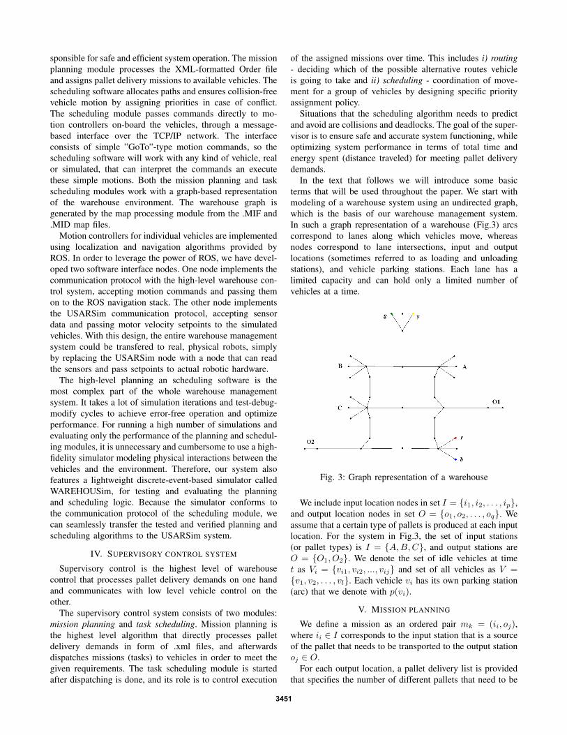
In the text that follows we will introduce some basicterms that will be used throughout the paper. We start withmodeling of a warehouse system using an undirected graph,which is the basis of our warehouse management system.In such a graph representation of a warehouse (Fig.3) arcscorrespond to lanes along which vehicles move, whereasnodes correspond to lane intersections, input and outputlocations (sometimes referred to as loading and unloadingstations), and vehicle parking stations. Each lane has alimited capacity and can hold only a limited number ofvehicles at a time.
Fig. 3: Graph representation of a warehouse
We include input location nodes in set I = {i1, i2, . . . , ip},and output location nodes in set O = {o1, o2, . . . , oq}. Weassume that a certain type of pallets is produced at each inputlocation. For the system in Fig.3, the set of input stations(or pallet types) is I = {A,B,C}, and output stations areO = {O1, O2}. We denote the set of idle vehicles at timet as Vi = {vi1, vi2, ..., vij} and set of all vehicles as V ={v1, v2, . . . , vl}. Each vehicle vi has its own parking station(arc) that we denote with p(vi).
V. MISSION PLANNING
We define a mission as an ordered pair mk = (ii, oj),where ii ∈ I corresponds to the input station that is a sourceof the pallet that needs to be transported to the output stationoj ∈ O.
For each output location, a pallet delivery list is providedthat specifies the number of different pallets that need to be
3451

transported to it. With all such delivery lists defined, missionplanning algorithm determines the set of missions that needto be done, and we denote this set as M = {m1,m2, ...,mn}.
For example if the pallet delivery list for warehousein Fig. 3 is provided only for station O2 and is givenas {A,B,B,C,C}, the set of missions is then M ={(A,O2), (B,O2), (B,O2), (C,O2), (C,O2)}.
The procedure for mission assignment is started at timet if there is an idle vehicle, which does not perform anymission (Vi 6= ∅) and there is at least one non-assignedmission (M 6= ∅).
Using an algorithm for vehicle dispatching, we need todetermine a mapping of the set of idle vehicles Vi on the(part of) the active missions set M , in order to minimize thetime needed to execute all active missions using the givenresources (vehicles).
While developing the described solution for 2011 VMAC,we evaluated several mission assignment algorithms, includ-ing simple cyclic selection of input and output station for avehicle, selection of an input/output location with the high-est number of requested pallets etc. The best performancewas achieved using the Munkres algorithm combined withsimulated annealing. These algorithms are described in thetext that follows.
A. Munkres algorithm
The first step towards solving the mission assignmentproblem is to calculate the performance cost of each missionin M by each vehicle in V . The cost ct(i, k) is calculatedas the shortest distance that the vehicle vi needs to cross,starting from its current position at time t, over the inputlocation, to the output location of the corresponding activemission mk. If the vehicle at time t executes a mission andis not idle, we take into account the path it needs to crossto finish its current mission.
The cost function that needs to be minimized in thisoptimization problem is given as:
Ct(x) =∑vi∈V
∑mj∈M
ct(i, j)xvimj , (1)
where:
xvimj =
{1 if vehicle vi is assigned to mission mj
0 otherwise(2)
A solution can be obtained using Munkres algorithm, oneof most known combinatorial optimization algorithms forlinear assignment problems in polynomial time [8]. Sinceour problem is not quadratic, we use the Munkres algorithmmodified for rectangular problems [9].
The output from the algorithm is an optimal assignmentstrategy X = {{vi,mj} : vi ∈ V,mj ∈ M}, such that inoptimal case mission mi is assigned to vehicle vj .
Having determined the strategy X , we calculate decisionfunction Xt ⊂ X , which includes only those pairs {vi,mj}where a mission is going to be assigned to a vehicle at timet. The decision function is such that a mission is assignedonly to currently idle vehicles.
A special case of the assignment problem that was givenin 2011 VMAC is a situation where a truck needs to deliversets of pallets at several different stops. To simplify palletunloading, one defines the order in which pallets need tobe loaded onto the truck. Missions corresponding to theoutput location (truck) ok can in that case be written as:(Mk1,Mk2, ...,Mkg) where all missions in set Mk1 mustdeliver pallets before missions in set Mk2, etc.
In this case, the algorithm first adds the set Mk1 tothe active mission set M (which is to be assigned duringthe optimization procedure). After all missions in set Mk1
deliver pallets, set Mk2 is added to M etc. Having the activemission set M determined, the procedure is the same as forsingle stop demand.
B. Simulated annealing
The objective of Munkres algorithm (1) is to minimizethe total distance traveled by the vehicles. However, shortertraveled distance does not necessary mean shorter time sincevehicles, in order to avoid collisions, must in many casesstop and let other vehicles pass. More vehicles sharingcommon route parts means more waiting, and eventuallya shorter route might become less favorable. Since it isinfeasible to predict possible collision situations, to get amore accurate assignment strategy, we modify optimizationproblem to penalize route overlapping. As the optimizationmethod, we use simulated annealing [5]. The starting pointfor the simulated annealing is the solution of the Munkresalgorithm.
A new cost matrix, Coverlap, is then calculated so thatthe cost of a route increases for the total length of itsoverlap with other routes. In each step of the algorithm, anew neighborhood solution is chosen by: i) assigning of adifferent task to a single vehicle or ii) swapping of tasks oftwo vehicles. If the cost of the neighboring solution is lowerthan the current cost, the neighbor is accepted as the new bestsolution. If it is of higher cost, it is accepted with certainprobability, which depends on variable T (temperature),and decreases as the algorithm evolves depending on thevalue of α cooling constant. Algorithm terminates after agiven number of iterations (Imax).
We will clarify the mission assignment procedure forthe situation given in Fig. 3 and active missions M ={(A,O2), (B,O2), (B,O2), (C,O2), (C,O2)}. All vehiclesare idle, that is, V = Vi = {b, r, g, y}. Since all vehiclesare idle, cost is the shortest distance needed to execute amission. The cost matrix is given as:
C0 =
m1 m2 m3 m4 m5
b 7806 7663 7663 5796 5796r 7805 7662 7662 5795 5795g 7407 5825 5825 5797 5797y 7410 5827 5827 5800 5800
The output from the Munkres algorithm is the following
mapping: X = {{b,m3}, {r,m4}, {g,m1}, {y,m2}}. In thenext part, this solution is forwarded to the simulated anneal-ing procedure with parameters: T = 5800, α = 0.6, Imax =
3452

10. Simulated annealing redispatches missions to penalizepath overlapping. The result is the modified assignment:X = {{b,m2}, {r,m1}, {g,m4}, {y,m3}}.
VI. TASK SCHEDULING
Having assigned missions to vehicles, the routing algo-rithm determines which route the vehicle is going to travel tosuccessfully finish the given mission. Routing can in generalbe static (route does not change during mission execution)and dynamic (route is allowed to change). Our approachcombines the properties of both approaches.
The basic idea behind the route assignment is that a vehiclecan be given a certain route if and only if it is safe, that is, ifall other missions can afterwards be finished without colli-sions and deadlocks. A trivial example for a non-safe route isone where a vehicle is blocking another vehicle, preventingit from finalizing its own mission. Route interactions can bevery complex even for medium-scale systems, which makesavoidance of similar situations difficult.
A new route is assigned to a vehicle in two specificsituations: i) a new missions is assigned to a vehicle ii)a vehicle has picked up a pallet at the input station i. Theassigned route consists of two parts:
1) path from the current position to the next (input/output)station
2) path from the next station to the parking stationWhen a new mission is assigned to a vehicle (v), theroute that is assigned first is the shortest possible. If thisassignment is not verified to be safe, the algorithm tries tofind a longer, but safe route. If there is not a single saferoute, the vehicle remains in its idle node (if no route hasbeen previously assigned to it), or continues to move alongits (safe) route to the parking station, continuously checkingwhether a safe route to the given input station i exists. Inthe worst case, a route will be assigned in its parking station[10].
The scheduling algorithm, which acts as a centralizedsupervisor, is called each time some vehicle arrives in frontof a node, which can correspond to a crossroad or a station.The algorithm knows the positions and routes for all vehiclesand its role is to allow or deny vehicle transfer to the nextarc on its route.
As we have said before, scheduling should verify thatthe system is always in a safe state, where there existat least one scenario of vehicles movements such that allmissions can be safely executed. All other states are eitherdeadlock or are going to inevitably end up in a deadlock.The vehicle transfer should be denied if and only if it willlead the system into a deadlock. Unfortunately, the problemof state safety verification is in general NP-complete [11], sovarious polynomial algorithms that identify only necessaryconditions for system safety are used today in practicalapplications.
Our approach, which is thoroughly described in [10], isbased on Banker’s algorithm [6]. According to the Banker’salgorithm, a state is safe if missions can finish sequentially,one by one. Since this is a rather conservative strategy, we
modified it to check not only if the requested transition issafe, but also if a vehicle can, by advancing on its route, getto a Banker’s safe state. This modification results in increasein vehicle utilization for certain types of layouts.
VII. PERFORMANCE EVALUATION IN USARSIM
The developed warehouse management solution is evalu-ated in both WAREHOUSim simulator and USARSim sim-ulation environment. System functionality and performancewere analyzed for the warehouse layout shown in Fig.1 for three different scenarios (S1, S2 and S3) given inTable II. Simulation included four Kiva-like vehicles. Foreach scenario, one pallet delivery list is provided for everytruck (T1, T2). All scenarios have the same total numberof packages, with a different number of stops that truckis required to make to deliver the packages to their finaldestinations. For example, in S2, truck T2 first needs to loadone A package for Stop 3, then one A and two C packages(in any order) for Stop 2, and one A and one B package forStop 1.
TABLE II: Delivery mission scenarios.
Stop1 Stop2 Stop3 WHSim USARSimT1 2A,3B,C - - AABBCB AABBCB S1T2 3A,B,2C - - CBCACA CBCAACT1 2A,3B,C - - AACBBB AACBBB S2T2 A,B A,2C A BA-CCA-A BA-CCA-AT1 A,B,C A,B B ACB-AB-B ACB-AB-B S3T2 A,B A,2C A ABC-CA-A BAC-AC-A
TABLE III: Algorithm performance metrics.
Distance Time Pallets Idle WaitingS1 818m 6:51 12 0% 11.64%S2 793m 7:56 12 1.78% 14.74% WHSimS3 814m 7:33 12 3.43% 15.33%S1 814m 20:40 12 0% 20.64%S2 801m 21:35 12 3.18% 21.3% USARSimS3 788m 18:12 12 4.6% 14.08%
Performance results are shown in Table III. For eachscenario we logged the total distance traveled, total timeneeded to fulfill the order, total number of pallets that aredelivered, the average time all vehicles spent idle in theirparking station and the average time each vehicle spentwaiting due to the scheduling policy restrictions.
Simulation results in both simulators show that the averageidle time increases with scenario complexity (number oftruck stops). That is due to the properties of mission planningalgorithm, which ensures that any missions correspondingto a certain truck stop can not be started before missionsfor all subsequent stops are done. The total time neededto finalize the order is lowest for scenario with one stop,that is, no order requirements. An interesting observationis that for the third scenario, S3, the USARSim simulationachieved the best performance in comparison with other two,which is an unexpected result. This is partially due to the factthat for real vehicles, like the ones simulated in USARSim,the time required to complete a delivery depends not only
3453
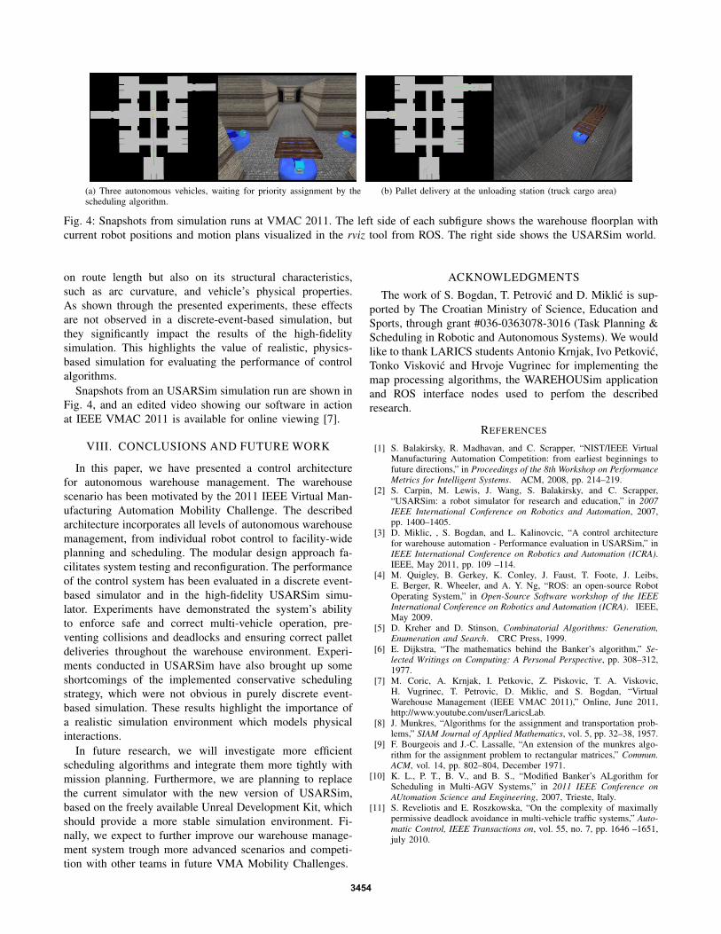
(a) Three autonomous vehicles, waiting for priority assignment by thescheduling algorithm.
(b) Pallet delivery at the unloading station (truck cargo area)
Fig. 4: Snapshots from simulation runs at VMAC 2011. The left side of each subfigure shows the warehouse floorplan withcurrent robot positions and motion plans visualized in the rviz tool from ROS. The right side shows the USARSim world.
on route length but also on its structural characteristics,such as arc curvature, and vehicle’s physical properties.As shown through the presented experiments, these effectsare not observed in a discrete-event-based simulation, butthey significantly impact the results of the high-fidelitysimulation. This highlights the value of realistic, physics-based simulation for evaluating the performance of controlalgorithms.
Snapshots from an USARSim simulation run are shown inFig. 4, and an edited video showing our software in actionat IEEE VMAC 2011 is available for online viewing [7].
VIII. CONCLUSIONS AND FUTURE WORK
In this paper, we have presented a control architecturefor autonomous warehouse management. The warehousescenario has been motivated by the 2011 IEEE Virtual Man-ufacturing Automation Mobility Challenge. The describedarchitecture incorporates all levels of autonomous warehousemanagement, from individual robot control to facility-wideplanning and scheduling. The modular design approach fa-cilitates system testing and reconfiguration. The performanceof the control system has been evaluated in a discrete event-based simulator and in the high-fidelity USARSim simu-lator. Experiments have demonstrated the system’s abilityto enforce safe and correct multi-vehicle operation, pre-venting collisions and deadlocks and ensuring correct palletdeliveries throughout the warehouse environment. Experi-ments conducted in USARSim have also brought up someshortcomings of the implemented conservative schedulingstrategy, which were not obvious in purely discrete event-based simulation. These results highlight the importance ofa realistic simulation environment which models physicalinteractions.
In future research, we will investigate more efficientscheduling algorithms and integrate them more tightly withmission planning. Furthermore, we are planning to replacethe current simulator with the new version of USARSim,based on the freely available Unreal Development Kit, whichshould provide a more stable simulation environment. Fi-nally, we expect to further improve our warehouse manage-ment system trough more advanced scenarios and competi-tion with other teams in future VMA Mobility Challenges.
ACKNOWLEDGMENTS
The work of S. Bogdan, T. Petrovic and D. Miklic is sup-ported by The Croatian Ministry of Science, Education andSports, through grant #036-0363078-3016 (Task Planning &Scheduling in Robotic and Autonomous Systems). We wouldlike to thank LARICS students Antonio Krnjak, Ivo Petkovic,Tonko Viskovic and Hrvoje Vugrinec for implementing themap processing algorithms, the WAREHOUSim applicationand ROS interface nodes used to perfom the describedresearch.
REFERENCES
[1] S. Balakirsky, R. Madhavan, and C. Scrapper, “NIST/IEEE VirtualManufacturing Automation Competition: from earliest beginnings tofuture directions,” in Proceedings of the 8th Workshop on PerformanceMetrics for Intelligent Systems. ACM, 2008, pp. 214–219.
[2] S. Carpin, M. Lewis, J. Wang, S. Balakirsky, and C. Scrapper,“USARSim: a robot simulator for research and education,” in 2007IEEE International Conference on Robotics and Automation, 2007,pp. 1400–1405.
[3] D. Miklic, , S. Bogdan, and L. Kalinovcic, “A control architecturefor warehouse automation - Performance evaluation in USARSim,” inIEEE International Conference on Robotics and Automation (ICRA).IEEE, May 2011, pp. 109 –114.
[4] M. Quigley, B. Gerkey, K. Conley, J. Faust, T. Foote, J. Leibs,E. Berger, R. Wheeler, and A. Y. Ng, “ROS: an open-source RobotOperating System,” in Open-Source Software workshop of the IEEEInternational Conference on Robotics and Automation (ICRA). IEEE,May 2009.
[5] D. Kreher and D. Stinson, Combinatorial Algorithms: Generation,Enumeration and Search. CRC Press, 1999.
[6] E. Dijkstra, “The mathematics behind the Banker’s algorithm,” Se-lected Writings on Computing: A Personal Perspective, pp. 308–312,1977.
[7] M. Coric, A. Krnjak, I. Petkovic, Z. Piskovic, T. A. Viskovic,H. Vugrinec, T. Petrovic, D. Miklic, and S. Bogdan, “VirtualWarehouse Management (IEEE VMAC 2011),” Online, June 2011,http://www.youtube.com/user/LaricsLab.
[8] J. Munkres, “Algorithms for the assignment and transportation prob-lems,” SIAM Journal of Applied Mathematics, vol. 5, pp. 32–38, 1957.
[9] F. Bourgeois and J.-C. Lassalle, “An extension of the munkres algo-rithm for the assignment problem to rectangular matrices,” Commun.ACM, vol. 14, pp. 802–804, December 1971.
[10] K. L., P. T., B. V., and B. S., “Modified Banker’s ALgorithm forScheduling in Multi-AGV Systems,” in 2011 IEEE Conference onAUtomation Science and Engineering, 2007, Trieste, Italy.
[11] S. Reveliotis and E. Roszkowska, “On the complexity of maximallypermissive deadlock avoidance in multi-vehicle traffic systems,” Auto-matic Control, IEEE Transactions on, vol. 55, no. 7, pp. 1646 –1651,july 2010.
3454