à - msi-viking.com · 23 11$33à./3(" +à".,/ 1 3.12 1ÕÇÇÅÄ à ÃÃÕÒÁÔÅà...
TRANSCRIPT


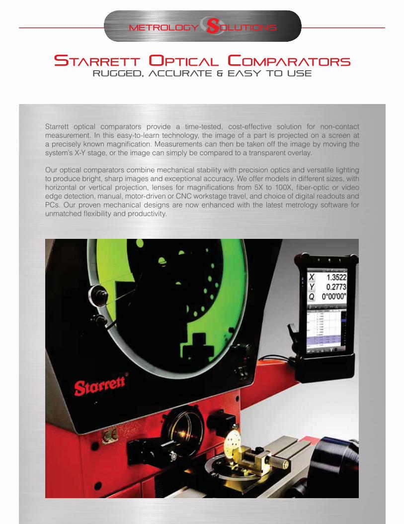
Starrett optical comparators provide a time-tested, cost-effective solution for non-contact measurement. In this easy-to-learn technology, the image of a part is projected on a screen at a precisely known magnification. Measurements can then be taken off the image by moving the system’s X-Y stage, or the image can simply be compared to a transparent overlay.
Our optical comparators combine mechanical stability with precision optics and versatile lighting to produce bright, sharp images and exceptional accuracy. We offer models in different sizes, with horizontal or vertical projection, lenses for magnifications from 5X to 100X, fiber-optic or video edge detection, manual, motor-driven or CNC workstage travel, and choice of digital readouts and PCs. Our proven mechanical designs are now enhanced with the latest metrology software for unmatched flexibility and productivity.

• 16" (400mm) diameter screen with crosslines, overlay
clips and hood
• Dual mirror design for vertically erect image
• 21.3"x5.1" (540x130mm) stage surface
• 12"x6" (300x152mm) of XY stage travel, 2” (50mm)
focus travel
• 110lb (50kg) maximum load capacity
• Bayonet lens socket for quick magnification changes
• All metal construction for optimum stability
• Fine adjustment for X and Y axes
• Fast traverse, zero backlash mechanism for X-axis
• Heidenhain glass scales for 0.00002" (0.5μm) X and Y
resolution
• Helix angle adjustment with ±15° Vernier scale
• 250W quartz halogen surface illumination with fiber-
optic delivery
• 150W quartz halogen profile illumination
• 5X, 10X, 20X, 25X, 31.25X, 50X, 100X projection lenses
• Fiber-optic edge detection
• OV2 Video Adapter for video edge detection
• Manual, motorized or CNC stage motion control
• Choice of Quadra-Chek digital readouts, tablet
computer with MetLogix M2 software, or all-in-one
touch-screen computer with MetLogix M3 software
• 23" (58cm) or 32" (81cm) cabinet stand
The Starrett HB400 horizontal optical comparator provides exceptional performance with a fully-usable 16" diameter viewing screen, a 21"x5" workstage, 12"x6" of stage travel, and high 110lb workload capacity. Linear glass scales provide 0.00002" (0.5μm) of resolution. A bayonet lens socket accepts a choice of seven lenses or an OV2 Video Adapter for video edge detection (VED). Optional optical edge detection removes operator subjectivity in locating edges.
The HB400 can be converted from optical comparator to vision metrology system operation when the Starrett OV2 Optical Video Adapter is installed in place of one of the two lenses in the lens slide. This provides the ultimate system flexibility.

Mounted to comparator arm x x x
Color graphics x x x
Touch-screen operation x x x
MS Windows operating system x x
X-Y-Q (angle) measurements x x x x
2D geometry software w/ skew x x x x
Optical edge detection option x x x x
Video edge detection option x x
CAD file import & export option x x
CNC drive option x x x
Software developer MetLogix Metronics / Heidenhain
Software on tablet PC with, color touch-screen (10"), 2D geometry software for point, line, circle, distance, angle and skew. Windows® 7 operating system and Wi-Fi network connectivity for import/export of CAD files and data. Supports optical edge detection and CNC control.
on an all-in-one PC. All features of the M2 tablet, but with a larger 21.5" touch-screen. Supports both optical edge detection and video edge detection.
QC221/ND1203 Digital Readout. Monochrome LCD screen (5.7"), sealed metal housing, 2D geometry software. Supports optical edge detection.
QC321/ND1303 Digital Readout. All features of the QC221/ ND1203, but with a larger color touch-screen (8.4"). Supports CNC control and either optical edge detection or video edge detection
Clockwise from the top:MetLogix M3Quadra-Chek QC321MetLogix M2 10" tablet
29” (730mm)
Starrett HD400
6” (150mm)
8” (200mm) 41” (1035mm)
43”
(108
5mm
)
Gross weight: 385lb (175kg)
Net Weight: 320lb (145kg)
Shipping dimensions: 47"x32"x50" (120x80x127cm).
The HB400 is available with a choice of seven projection lenses and the Starrett OV2 Optical Video Adapter, a video camera which can be installed in place of a projection lens to provide video edge detection (VED). All lens assemblies and the OV2 are mounted by a bayonet fitting, which allows quick changeover between magnifications or between optical projector and VED operation.
Starrett manufactures a comprehensive range of fixtures and accessories for our line of optical comparators. Each accessory is made from the highest material and is machined, assembled and inspected to the same stringent quality standards as the comparator itself.
Precision Centers and Vees
Rotary Vee Blocks
Rotary Vises Cabinet Stands
Vertical Glass Plate Holders
Magnification Check Gradules
Fixed Vises
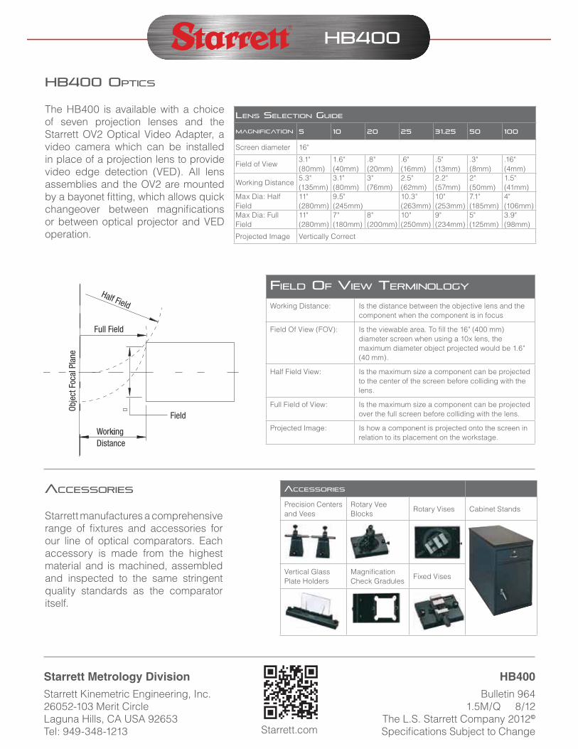
Half Field
Full Field
Obje
ct F
ocal
Pla
ne
WorkingDistance
Field
Starrett Kinemetric Engineering, Inc. 26052-103 Merit Circle Laguna Hills, CA USA 92653 Tel: 949-348-1213
Bulletin 964 1.5M/Q 8/12
The L.S. Starrett Company 2012Specifications Subject to ChangeStarrett.com
Screen diameter 16"
Field of View3.1"(80mm)
1.6"(40mm)
.8"(20mm)
.6"(16mm)
.5"(13mm)
.3"(8mm)
.16"(4mm)
Working Distance5.3"(135mm)
3.1"(80mm)
3"(76mm)
2.5"(62mm)
2.2"(57mm)
2"(50mm)
1.5"(41mm)
Max Dia: Half Field
11"(280mm)
9.5"(245mm)
10.3"(263mm)
10"(253mm)
7.1"(185mm)
4"(106mm)
Max Dia: Full Field
11"(280mm)
7"(180mm)
8"(200mm)
10"(250mm)
9"(234mm)
5"(125mm)
3.9"(98mm)
Projected Image Vertically Correct
Working Distance: Is the distance between the objective lens and the component when the component is in focus
Field Of View (FOV): Is the viewable area. To fill the 16" (400 mm) diameter screen when using a 10x lens, the maximum diameter object projected would be 1.6" (40 mm).
Half Field View: Is the maximum size a component can be projected to the center of the screen before colliding with the lens.
Full Field of View: Is the maximum size a component can be projected over the full screen before colliding with the lens.
Projected Image: Is how a component is projected onto the screen in relation to its placement on the workstage.