a multi-environment thermal control system with … · a multi-environment thermal control system...
TRANSCRIPT

American Institute of Aeronautics and Astronautics
1
A Multi-Environment Thermal Control System With Freeze-Tolerant Radiator
Weibo Chen, David Fogg, Nick Mancini Creare Inc., Hanover, New Hampshire, 03755
John Steele, Gregory Quinn United Technologies Corporation Aerospace Systems, Windsor Locks, Connecticut, 06096
Grant Bue, Sean Lillibridge NASA Lyndon B. Johnson Space Center, Houston, Texas, 77062
Future space exploration missions require advanced thermal control systems (TCS) to dissipate heat from spacecraft, rovers, or habitats operating in environments that can vary from extremely hot to extremely cold. A lightweight, reliable TCS is being developed to effectively control cabin and equipment temperatures under widely varying heat loads and ambient temperatures. The system uses freeze-tolerant radiators, which eliminate the need for a secondary circulation loop or heat pipe systems. Each radiator has a self-regulating variable thermal conductance to its ambient environment. The TCS uses a nontoxic, water-based working fluid that is compatible with existing lightweight aluminum heat exchangers. The TCS is lightweight, compact, and requires very little pumping power. The critical characteristics of the core enabling technologies were demonstrated. Functional testing with condenser tubes demonstrated the key operating characteristics required for a reliable, freeze-tolerant TCS, namely (1) self-regulating thermal conductance with short transient responses to varying thermal loads, (2) repeatable performance through freeze-thaw cycles, and (3) fast start-up from a fully frozen state. Preliminary coolant tests demonstrated that the corrosion inhibitor in the water-based coolant can reduce the corrosion rate on aluminum by an order of magnitude. Performance comparison with state-of-the-art designs shows significant mass and power saving benefits of this technology.
I. Introduction Future spacecraft, rovers, and habitats will require high-performance thermal control systems that can dissipate a
wide range of heat loads in harsh thermal environments. Environmental temperatures can vary by more than 200 K during each environmental cycle (Stephan 2011) and heat loads can change by an order of magnitude when the power supply mainly comes from solar panels. However, cabin temperatures must be controlled within a narrow range to ensure the comfort of crew members and to reduce thermal stresses in electronic components and other equipment. Therefore, a future TCS must be able to vary the thermal conductance between the cabin and the ambient over a wide range. Furthermore, when the cabin heat load is low and ambient is very cold, temperatures in radiators can fall below the freezing point of the working fluid. Fluid freezing poses many hazards. One such hazard is potential rupture of the radiator tubes due to the expansion of the working fluid during local freezing or thawing processes. Another problem is the very slow thawing process during which the TCS will not be able to achieve its full heat dissipation capacity. Several approaches have been studied to achieve variable thermal conductance and freeze-tolerance. For example, a two-loop configuration was studied for NASA Altair Lunar Lander (Stephan 2011). This approach uses a secondary circulation loop with working fluid that has a freezing temperature well below the minimum environment temperature that the radiator would experience. This requires an interface heat exchanger between the loops and a separate circulation pump for the secondary loop. Furthermore, working fluids with low freezing temperatures typically have poor thermal and fluid properties, requiring larger heat exchangers or higher pumping power. A variation of this approach uses loop heat pipes to eliminate the circulation pump; however, this adds complexity during start-up and mass to the system. Other approaches to prevent freezing include (1) using survival heaters to prevent working fluid from freezing, (2) actively controlling radiator conductance by varing the radiator exposed
https://ntrs.nasa.gov/search.jsp?R=20130011331 2018-08-25T08:18:08+00:00Z

American Institute of Aeronautics and Astronautics
2
surface areas or surface effective emissivity (Bannon et al. 2010), (3) removing working fluid from some of the radiator tubes to reduce active areas and therefore the heat dissipation capacity (Ganapathi et al. 2009), and (4) allowing working fluid to freeze on the internal surfaces of radiator tubes while maintaining a small liquid flow through the center of the tubes (Nabity et al. 2008). However, all these methods incur some performance penalties in terms of mass, power, reliability, and recovery time, or pose technical challenges due to their low TRL. For these reasons, there is a strong need for an alternative lightweight, reliable TCS that self regulates its thermal conductance and can tolerate freezing of its working fluid.
II. TCS With Freeze-Tolerant and Varaiable-Conductance Radiator A single-loop TCS with freeze-tolerant radiator that has variable thermal conductance is being developed at
Creare. As shown in Figure 1, the TCS uses a single-phase circulation loop inside the cabin for heat acquisition and transfer, and a low-pressure, two-phase loop outside the cabin for heat rejection. Single-phase circulating water in the hot portion of the circulation loop is cooled in a membrane evaporator by evaporating a very small fraction of the circulating water. The resulting water vapor condenses in the freeze-tolerant condenser, which has a self-regulating thermal conductance to control the heat rejection rate. The condenser has unique design features that allow water vapor to flow into the condenser and condensate to flow out of the condenser even when a large section of the condenser tube is frozen, thus enabling the radiator to continue to work effectively. An ejector pump then draws the condensate from the external condenser back into the main loop. Each radiator passively self-regulates its thermal conductance to the ambient environment, giving them heat rejection turndown ratios higher than 20. The pumped coolant loop uses a benign working fluid that consists mainly of water with a very low concentration of corrosion inhibitors and biocides, which ensures the working fluid is compatible with existing aluminum heat exchangers, crew health, and vehicle systems.
Figure 1. Layout of a Single-Loop TCS With Freeze-Tolerant Condensers/Radiators Having a Variable Thermal Conductance
The TCS also can provide a very high cooling power if needed by directly venting water vapor to the external environment. The vent valve in the TCS also allows venting of noncondensable gas in the condensers during scheduled maintenance.
The TCS combines components that are being developed at Creare, and technologies that have already been developed at NASA JSC and United Technologies Corporation Aerospace Systems (UTAS) to create a thermal control system that will meet the challenges of temperature control on future manned spacecraft. The three key elements in the TCS and their features are discussed below.

American Institute of Aeronautics and Astronautics
3
Subcooled, Single-Phase Loop Inside Cabin. The single-phase loop inside the cabin is pressurized to a level high enough to provide sufficient subcooling to prevent two-phase flow in this loop. This allows the use of simple single-phase heat exchangers to absorb heat. Using a single-phase loop also eliminates potential flow instability associated with two-phase flows and thus simplifies system design, operation, control, and maintenance. This is especially true in a system that has multiple cold plates with different flow resistances and heat loads. The subcooling also prevents cavitation in circulation pumps, simplifying pump design and enhancing pump reliability. The pumps control the loop circulation flow rate to maintain the cabin temperature. These design features lead to a compact, lightweight TCS with a large heat transfer capacity.
Direct Evaporative Chiller. Heat rejection from the single-phase loop is accomplished by direct evaporative cooling. A small fraction of the circulation water evaporates to cool the bulk circulating flow. The resulting water vapor flows to the parallel radiation-cooled condensers outside the cabin. The condensate is drawn back to the loop inside the cabin with a passive, cavitation-tolerant ejector pump. For a fixed evaporation pressure, the heat rejection rate in the evaporative chiller can be controlled by the circulation water flow rate. Due to the high heat transfer coefficient associated with the evaporation process, the evaporative chiller is far more compact than a single-phase, liquid-to-liquid heat exchanger in a conventional system using a secondary loop. Furthermore, for a given size radiator panel, the maximum heat rejection capacity of a two-phase flow is appreciably higher than that of a single-phase flow. This is because the temperature of a two-phase flow does not decrease as it flows across the condenser, while a single-phase flow always does. Compared to a system using heat pipes (including loop heat pipes) in its external secondary loop, our system eliminates the need for interface heat exchangers, heat pipe accumulators, and bypass control needed in extremely cold environments. Current heat pipes also have the shortcoming of limited heat transport capacity and operating stability issues associated with multiple condensers.
The configuration of the internal portion of our TCS is similar to the liquid cooling loop in future spacesuits incorporating the Spacesuit Water Membrane Evaporator (SWME) currently under study by NASA for evaporative cooling (Bue and Makinen 2011). Our TCS eliminates water venting by incorporating radiation cooled condensers to condense water vapor and draw the condensate back inside the cabin. Minimizing consumables is critical for future long-duration exploration missions.
Freeze-Tolerant Condensers/Radiators. The radiation cooled condenser is freeze-tolerant and has design features that self-regulate its thermal conductance to the ambient environment. The variable conductance allows the TCS to maintain a stable evaporation pressure for the evaporative chiller, and thus a stable cabin temperature even when the variations in cabin heat loads and ambient temperature are large. The freeze-tolerant condensers also enable water as working fluid. This eliminates the need for other working fluids with very low freezing temperatures that have much poorer thermophysical properties relative to water.
III. Condenser/Radiator Design Optimization Condenser Design Features. The radiation-cooled condensers are designed to tolerate freezing of the working
fluid and yet continue to reject heat. Compared with other radiator designs, the key difference in this condenser/radiator is the continuous connection between the vapor channel and the condensate return channel.
The condenser has three distinct operating regions. Close to the vapor inlet is the active region operating at the inlet vapor temperature; at the distal end is the inactive region at the effective sink temperature; and in between lies a short transition zone. The length of the active region is proportional to the condensation rate. It increases with TCS input power which leads to more vapor. The length of the active region also increases when the effective sink temperature is increased due to the lower local condensation heat flux. When the active regime extends to the distal end of the condenser tube, the condenser heat rejection capacity reaches its maximum value. This ability of the condenser to regulate the length of its own active region enables it to achieve a variable thermal conductance to the ambient environment.
With a relatively uniform heat sink temperature over the entire radiator panel, the far end of the condenser tube will always be at the lowest temperature of the entire tube. Therefore, water will tend to start to freeze at that end. The frozen section will gradually extend toward the vapor inlet as the heat load decreases or the ambient temperature decreases. This behavior will prevent water from being trapped between two iced sections. This feature prevents excessive stresses in the condenser tube associated with fluid expansion during freeze-thaw cycles.
Condenser Design Analysis. To maintain a comfortable cabin environment, the evaporative chiller needs to operate at a saturation temperature below 20°C. The corresponding saturation vapor pressure is only 17.5 torr. Therefore, pressure drop within the vapor lines connecting the evaporative chiller to condensers must be limited to no more than 2 torr. This low-pressure drop requirement, coupled with the low density of water vapor, necessitates a condenser tube with a relatively large diameter. Other design constraints for the condenser/radiator, including the

minimum panel lengt
Given rejection ra38.4 W at f
The tradimensionsanalysis coin the cond
Figure 5 min, the and 90% oraised to 3the two-phcan recovethe freezinsaturation p
Figure 2.temperatuthe vapor
Figure two-phase power, as eof the froze
tube wall thickth, are imposedthese constrainate. The optimfull power withansient thermas, radiator heaode predicts thedenser. 2 shows the pradiator opera
of condenser len5 W, the two-p
hase zone expaner very quicklyng process (t =pressure.
Predicted Rures at locatioinlet.
3 shows the rzone decrease
expected. At then zone is abou
Americ
kness for the cd in the radiatonts, the design
mal design is a h a heat sink te
al response of at load profile, e time-varying
predicted thermates at a steadyngth is at tempphase region qnds to a length
y from a nearly= 120 min). T
Response of ns that are 10
radiator respones approximatehe input powerut 40% of the c
can Institute of
condenser, the or design optimn parameters fo
1 m long paneemperature of 2the radiator issaturation tem
g radiator tempe
mal response o state with the
peratures well bquickly advanch of about 80%y fully frozen sThe pressure d
Freeze-Tolera0 cm apart. Th
nses to an inpuely proportionar of 20 W, whicondenser leng
f Aeronautics a
4
minimum radmization procesor the panel arel with a cond200 K. s calculated wimperature, sinkerature profile,
f the radiator ttwo-phase zon
below the freezces and melts th
% of the condenstate. Figure 2drop during th
ant Radiator he first and la
ut power step-dally. The pressich is about 50
gth.
and Astronauti
diator panel thiss. re optimized fodenser tube pitc
ith a 2-D numk temperature, , pressure drop
to a power ramne extending ozing point. Whhe ice downstrnser tube. This2 also shows thhe entire proce
r to a Powerast locations a
down. As the psure drop acros0% of the radia
ics
ickness, and th
or minimum mch of 0.150 m
merical model. and panel init
p, and the lengt
mp from 5 W only about 5 cmhen the heat loaream. Within l analysis confi
he effect of latess remains le
r Ramp. Solare 0.05 m and
power decreasss the radiatorator maximum
he minimum ra
mass for a givecapable of rej
Based on thetial temperatureth of two-phas
to 35 W. Befom into the conad is instantanless than 10 miirms that the ratent heat of fusess than 10%
lid lines repd 0.95 m away
ses, the length r also decrease
m capacity, the
adiator
en heat jecting
e panel es, the e zone
ore t = denser eously inutes, adiator sion in of the
resent y from
of the es with length
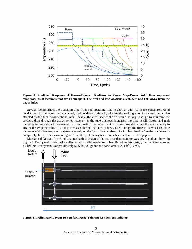
Figure 3. temperatuvapor inle
Severalconductionaffected bypressure drincreases iabsorb theincreases wcompletely
MechanFigure 4. Ea 6 kW rad
Figure 4. P
LiquidReturn
Start-upheater
Predicted Rures at locationet.
l factors affectn via the watery the tube crosrop through thin proportion t
evaporator hewith diameter, y thawed, as shnical Design. A
Each panel condiator system is
Preliminary L
d n
p
Americ
Response of Fns that are 10
t the transitionr, radiator panss-sectional arhe active zoneo volume store
eat load that inthe condenser
hown in Figure A preliminary
nsists of a colles approximatel
Layout Design
Vapor Inlet
can Institute of
Freeze-Tolera0 cm apart. Th
n time from onnel, and condenrea. Ideally, the; however, as ed. Fortunately
ncreases duringcan rely on the2 and the prelmechanical de
ection of parallly 50.5 lb (23 k
for Freeze-To
f Aeronautics a
5
nt Radiator he first and las
ne operating lonser primarily e cross-sectionthe tube diam
y, the latent heg the thaw proe fusion heat toiminary test reesign of the ralel condenser tukg) and the pan
olerant Conde
1m
and Astronauti
to Power Stst locations ar
oad to anotherdictates the m
nal area wouldmeter increaseseat of fusion p
ocess. Even thoo absorb its ful
esults discussedadiator demonsubes. Based on
nel area is 250
enser/Radiato
ics
tep-Down. Sore 0.05 m and
r with ice in tmelting rate. Rd be large enou, the time to f
provides ampleough the time ll heat load befd later in this pstrator was devn this design, thft2 (23 m2).
or
olid lines repr0.95 away fro
the condenser. Recovery time i
ugh to minimifill, freeze, ande thermal capato thaw a largfore the conden
paper. veloped, as shohe predicted m
resent om the
Axial is also ize the d melt city to
ge tube nser is
own in mass of

American Institute of Aeronautics and Astronautics
6
IV. Ejector Pump Design The ejector pump is a critical system component responsible for returning the low-pressure condensate in the
radiator panel back to the high-pressure cabin loop. To raise the pressure of the condensate back to the cabin loop pressure, our approach is to use a single-stage ejector that uses a small flow of high-pressure water from the main circulation loop to raise the condensate pressure to an intermediate pressure, e.g., 10 psia, and then employ a small booster pump to complete the process. The intermediate pressure only needs to be high enough to avoid cavitation in the booster pump. For a 6 kW cooling system, the primary flow rate is only about 4 g/s, or 32 lb/hr. This is only about 10% of the main pump flow rate. The ideal power input for the booster pump is only about 1.5 W.
We completed scoping analyses to develop a preliminary ejector pump design that will recirculate radiator condensate with 5°C of subcooling using a primary motive stream at 45 psia. To prevent cavitation in the suction flow, which would increase suction flow volumetric flow rate and thus reduce the ejector entrainment ratio, we limit the maximum acceleration pressure drop from the suction inlet to the mixing chamber inlet to less than 0.05 psi. As a result, the suction flow area must be relatively large.
A preliminary ejector design, with dimensions determined from conservation laws and empirical diffuser performance maps, was analyzed with a CFD model for incompressible fluid. Figure 5 shows the ejector pump model. The nozzle diameter is only about 0.5 mm.
Figure 5. CAD Model of a Preliminary TCS Ejector Pump
The computational domain is axisymmetric and thus only a 20-degree section of the entire ejector was modeled. Mesh refinement near the walls and mixing regions resolves boundary layer growth (particularly in the diffuser), as well as the shearing region where the high-speed nozzle exit flow and the entrained suction flow meet. Pressure boundary conditions are imposed at the inlet (45 psia), suction inlet (0.26 psia), and diffuser outlet (11 psia), and the resulting mass flow rates were determined from the CFD results.
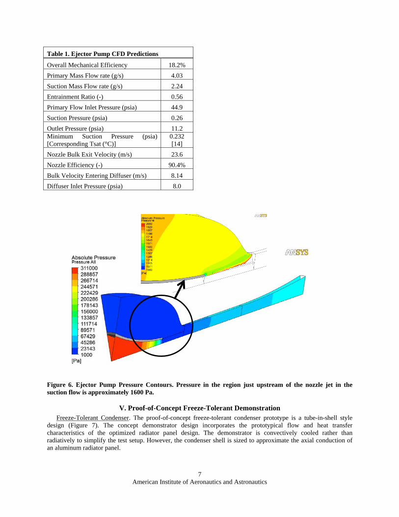
The resulting primary flow rate is 4.03 g/s and the suction flow rate is 2.24 g/s, corresponding to an entrainment ratio of 0.56 with an ideal exit pumping power of 1.47 W. Table 1 provides a summary of all key ejector performance data predicted by the CFD analysis.
Figure 6 shows the pressure contours within the ejector. The ejector design includes a larger suction throat which reduces the acceleration pressure drop and thus cavitation potential. The minimum pressure in this region is about 1600 Pa which corresponds to a saturation temperature of 14°C. Short regions of sub-saturation pressures are allowable as the cavitation bubbles have fast, but finite growth rates. If the fluid transit period across the low-pressure region is sufficiently small, minute vapor bubbles might not have adequate time to grow before entering higher pressure regions where they will condense.
The CFD results were also used to iteratively determine the optimum length of the mixing section. The mixing section must be long enough to allow the suction flow and primary flow to reach the same speed and pressure. An excessively long mixing chamber, however, can cause large flow losses due to wall friction. We iteratively adjust the chamber length to maximize the ejector performance (i.e., maximize suction flow rate) for the given pressure boundaries.
Primary flow
Suction flow
Mixing Chamber
Diffuser
Nozzle
Outlet
American Institute of Aeronautics and Astronautics
7
Table 1. Ejector Pump CFD Predictions
Overall Mechanical Efficiency 18.2%
Primary Mass Flow rate (g/s) 4.03
Suction Mass Flow rate (g/s) 2.24
Entrainment Ratio (-) 0.56
Primary Flow Inlet Pressure (psia) 44.9
Suction Pressure (psia) 0.26
Outlet Pressure (psia) 11.2 Minimum Suction Pressure (psia) [Corresponding Tsat (°C)]
0.232 [14]
Nozzle Bulk Exit Velocity (m/s) 23.6
Nozzle Efficiency (-) 90.4%
Bulk Velocity Entering Diffuser (m/s) 8.14
Diffuser Inlet Pressure (psia) 8.0
Figure 6. Ejector Pump Pressure Contours. Pressure in the region just upstream of the nozzle jet in the suction flow is approximately 1600 Pa.
V. Proof-of-Concept Freeze-Tolerant Demonstration Freeze-Tolerant Condenser. The proof-of-concept freeze-tolerant condenser prototype is a tube-in-shell style
design (Figure 7). The concept demonstrator design incorporates the prototypical flow and heat transfer characteristics of the optimized radiator panel design. The demonstrator is convectively cooled rather than radiatively to simplify the test setup. However, the condenser shell is sized to approximate the axial conduction of an aluminum radiator panel.

American Institute of Aeronautics and Astronautics
8
Figure 7. Phase I Prototype Condenser Design
Prototypical Condenser Test Facility. Figure 8 provides a schematic of the test facility to demonstrate the key features of the freeze-tolerant condenser. The major components consist of a low-pressure evaporator, a prototypical condenser tube, and a convectively cooled radiator load simulator.
The evaporator consists of a stainless steel tube, an internal circulating micro-pump, an external tape heater, and a liquid spray tube. The evaporator simulates the output vapor flow from a membrane evaporative chiller in an actual TCS. The vapor production rate is adjusted using the tape heater. A high-accuracy pressure gauge provides precise measurement of the saturation pressure, and consequently, saturation temperature. A T-type thermocouple immersed in the evaporator provides a secondary check of the vapor state leaving the evaporator.
Figure 8. Schematic of Test Facility
An outer tube surrounding the condenser tube serves as a radiative load simulator. Air circulates through the annular gap between the condenser tube and the simulator shell to convectively cool the condenser. The thermal resistance from the condensed vapor to the air flow is representative of the resistance from the condensing vapor to the radiative heat sink in actual applications. A propylene glycol-water loop flows in a counter-flow heat exchanger to chill the air prior to the radiative load simulator.
Ten thermocouples were installed axially along the condenser tube. The tip of each thermocouple is positioned in the midpoint of the condenser tube wall and reflects the fluid temperature inside the condenser. The array of thermocouples provides information regarding the axial temperature profile inside the condenser, allowing us to observe how the active and frozen condenser lengths change depending on the load. The temperature change of the
Condenser Outer Tube
Embedded Thermocouples
Cooling Jacket
air across tthe condenthermocou
Condenthe freeze-(2) effectiv
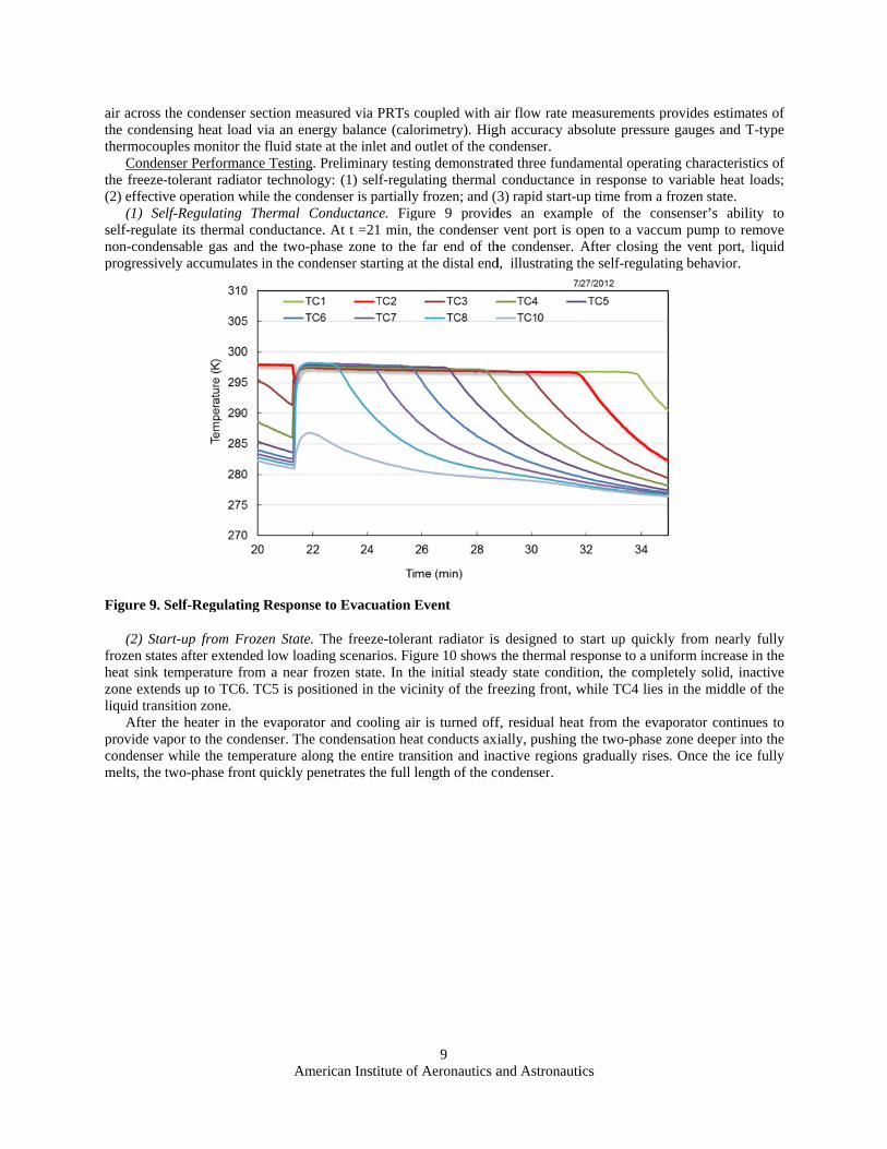
(1) Selself-regulanon-condeprogressive
Figure 9. S
(2) Stafrozen statheat sink tzone extenliquid trans
After thprovide vacondenser melts, the t
the condenser nsing heat loaduples monitor thnser Performan-tolerant radiatve operation whlf-Regulating
ate its thermal nsable gas andely accumulate
Self-Regulatin
art-up from Fres after extendtemperature fronds up to TC6.sition zone. he heater in th
apor to the condwhile the temtwo-phase fron
Americ
section measud via an energyhe fluid state ance Testing. Prtor technologyhile the condenThermal Conconductance. Ad the two-phases in the conde
ng Response to
rozen State. Thded low loadingom a near froz TC5 is positio
he evaporator adenser. The co
mperature alongnt quickly pene
can Institute of
ured via PRTs cy balance (calo
at the inlet and reliminary testi: (1) self-regulnser is partially
nductance. FigAt t =21 min, se zone to the
enser starting at
o Evacuation E
he freeze-tolerg scenarios. Figzen state. In thoned in the vic
and cooling aiondensation heag the entire tranetrates the full l
f Aeronautics a
9
coupled with aorimetry). Higoutlet of the coing demonstratlating thermal y frozen; and (3gure 9 providthe condenser
e far end of tht the distal end
Event
rant radiator isgure 10 shows he initial steadcinity of the fre
ir is turned offat conducts axinsition and inalength of the c
and Astronauti
air flow rate mgh accuracy abondenser. ted three fundaconductance i
3) rapid start-udes an exampr vent port is ohe condenser. Ad, illustrating th
s designed to sthe thermal re
dy state conditeezing front, w
f, residual heatially, pushing tactive regions ondenser.
ics
measurements pbsolute pressure
amental operatiin response to up time from a ple of the conopen to a vaccuAfter closing the self-regulat
start up quickesponse to a untion, the compwhile TC4 lies
t from the evathe two-phase gradually rise
provides estimae gauges and T
ing characterisvariable heat frozen state. nsenser’s abilum pump to rethe vent port, ting behavior.
ly from nearlyniform increaseletely solid, inin the middle
aporator continzone deeper ins. Once the ice
ates of T-type
stics of loads;
lity to emove liquid
y fully e in the nactive
of the
nues to nto the e fully

Figure 10.
(3) Freloading corapidly abssuch cyclitemperatur
Figure 11.
The conthe condenheater pow
. Start-up Fro
eeze-Thaw Cyconditions. The sorb the heat asic loading is dre remained fix
. Freeze-Thaw
ndenser starts nser inlet valvewer is set to 0
Americ
m Near Froze
cles. Orbiting sradiator must
s heat load incdepicted in Fi
xed throughout
w Cycle Behav
at a steady cone is closed, preW followed s
can Institute of
en State
pacecraft and pbe able to ac
reases at otherigure 11. In tt the test.
vior
ndition dissipateventing vapor hortly by an i
f Aeronautics a
10
periodic equipccommodate frr points. The abthis scenario,
ting 45 W withfrom flowing
ncrease to 18
and Astronauti
pment operationreezing duringbility of the frethe convectiv
h an active reginto the condeW. The conde
ics
n will subject tg cold or low eeze-tolerant coe cooling air
gion extending enser. At this penser increases
the radiator to loading phaseondenser to adflow rate and
to TC4. At 11point, the evaps the inactive
cyclic es, and djust to d inlet
5 min, porator region

American Institute of Aeronautics and Astronautics
11
from TC5 to TC2. At 170 min, the condenser inlet valve is opened with the heater power returning to 45 W. The active, two-phase zone advances in response to the increased heat load. Axial conduction begins the melting process of the frozen zone. Within 15 minutes, the condenser has regulated itself to a point where it is rejecting the increased load, despite the fact that the melting process is not complete. The latent heat of fusion allows the radiator to accomodate a fast power ramp to its full design load even though the time to reestablish a steady operating state takes nearly 40 minutes. This example clearly demonstrates the freeze-tolerance capability.
VI. Demonstration of Biocide and Corrosion Inhibitors
Water is the most benign working fluid and has the best transport and thermodynamic properties. However, pure water is corrosive to pipes and heat exchangers made of aluminum alloys. To overcome this problem and to prevent formation of biofilm, corrosion inhibiting and biocidal additives must be introduced in the water. UTAS has identified a promising organic acid-based corrosion inhibition package for water in aluminum heat exchangers. Test results show that the additives are stable over a wide temperature range (275 K to 333 K) and through a 24-hour freeze/thaw cycle. Furthermore, short-term corrosion test data indicate greater than an order of magnitude reduction in aluminum corrosion rate. The results of this development effort are briefly discussed below.
An iterative process was undertaken to determine the appropriate concentration of each ingredient in the water-based coolant. This was a balancing act between ideal target concentrations and the solubility of the mixture in the target temperature range (275 K to 333 K) and through a freeze/thaw cycle. Solubility was based on visual examination of the solutions to ensure clarity with no signs of precipitation and/or stratification.
CPP (Cyclic Potentiodynamic Polarization) was used as an analysis tool to estimate the corrosion rate of aluminum alloy heat exchanger material in the subject coolant. Tafel extrapolation per ASTM G 102 was performed on the CPP data curves to provide a corrosion rate estimate. This method is also capable of revealing any tendency for pitting for the combination of material and environment (in this case, the subject coolant). Aluminum Alloy 6951 samples were soaked in the coolant solution for approximately 2.5 weeks before testing.
Figure 12 represents the results of a CPP corrosion test. These curves are plots of the log of corrosion current in amperes (amperes per square centimeter for a 1 cm2 sample) as a function of polarization potential in volts vs. a Saturated Calomel Electrode (S.C.E.). The red curves give the raw data, and the green curve shows the curve model used in the Tafel Extrapolation, which gave corrosion rates of 0.229 mpy for this trial.
Figure 13 shows the generic corrosion rate of aluminum as a function of pH value. At a pH value of 7.8 (the pH of the developed coolant), the corrosion rate is ~0.1 mm per year (or 3.9 mpy). This was used as a baseline data point to compare to the corrosion rate of Al 6951 alloy coupons submerged in the subject coolant for a two-week period of time. It should be noted that the pH of water with no buffer is expected to increase over time when in contact with aluminum due to the generation of aluminum hydroxide corrosion products. The corrosion rate, therefore, would be expected to increase over time with no buffer.

American Institute of Aeronautics and Astronautics
12
Figure 12. CPP Corrosion Test With Tafel Extrapolation in Water Based Coolant. Corrosion rate = 0.229 MPY.
Figure 13. Generic Corrosion Rate of Aluminum in Water1
Additionally, UTAS has developed a micro-gravity compatible means to introduce a long-acting, low vapor pressure biocide (ortho-phthalaldehyde) to water-based coolant systems. This biocide has been implemented on the International Space Station in the Internal Active Thermal Control System (IATCS) and has demonstrated high antimicrobial character lasting several months at a time from a single dose.
VII. Performance Comparison With Other Technologies A preliminary study was conducted by UTAS to compare the freeze-tolerant radiator and TCS mass to the mass
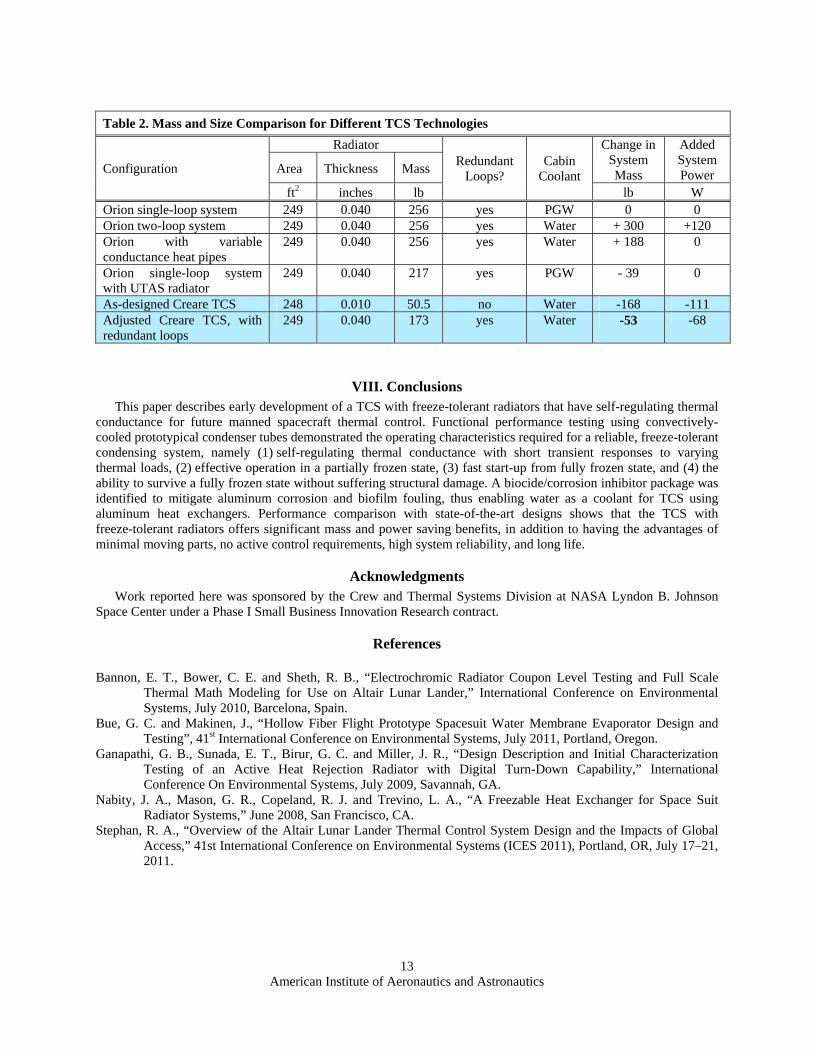
of other TCS and radiator combinations. Comparisons were made to the Orion TCS and radiator and to a lightweight body-panel UTAS radiator design. The preliminary freeze-tolerant radiator design was adjusted to have the same area, thickness, and redundancy as the competing radiators, while the Creare TCS mass and power were adjusted for the specific set of valves and pumps that are unique to that system. As shown in Table 2, the study by UTAS showed that Creare’s radiator mass is 43 lb lighter than the lightweight UTAS radiator mass while the system-specific components such as boost pumps, ejectors, and isolation valves only add about 30 lb back to the system. As a result, the total mass and power of Creare’s TCS is 13 lbm less than what might be considered an Orion single-loop TCS. Creare’s TCS also benefits from pumping water instead of a 50/50 mix of propylene glycol and water, which saves pumping power in the primary coolant loop. Even when considering the need for boost pumps, the power savings would be about 68 watts compared to the single-loop Orion baseline and 188 watts compared with the two-loop Orion system. More importantly, Creare’s TCS has the benefit of using water as a nontoxic coolant inside the cabin, and the coolant is compatible with lightweight aluminum heat exchangers.
1 <http://www.corrosion-doctors.org/Corrosion-by-Water/Constituents.htm>
10-10 10-9 10-8 10-7 10-6 10-5 10-4-1.0
-0.5
0
0.5
1.0
I (Amps/cm2)
E (
Vol
ts)
vs.
S.C
.E.
American Institute of Aeronautics and Astronautics
13
Table 2. Mass and Size Comparison for Different TCS Technologies
Configuration
Radiator Redundant
Loops? Cabin
Coolant
Change in System Mass
Added System Power Area Thickness Mass
ft2 inches lb lb W Orion single-loop system 249 0.040 256 yes PGW 0 0 Orion two-loop system 249 0.040 256 yes Water + 300 +120 Orion with variable conductance heat pipes
249 0.040 256 yes Water + 188 0
Orion single-loop system with UTAS radiator
249 0.040 217 yes PGW - 39 0
As-designed Creare TCS 248 0.010 50.5 no Water -168 -111 Adjusted Creare TCS, with redundant loops
249 0.040 173 yes Water -53 -68
VIII. Conclusions This paper describes early development of a TCS with freeze-tolerant radiators that have self-regulating thermal
conductance for future manned spacecraft thermal control. Functional performance testing using convectively-cooled prototypical condenser tubes demonstrated the operating characteristics required for a reliable, freeze-tolerant condensing system, namely (1) self-regulating thermal conductance with short transient responses to varying thermal loads, (2) effective operation in a partially frozen state, (3) fast start-up from fully frozen state, and (4) the ability to survive a fully frozen state without suffering structural damage. A biocide/corrosion inhibitor package was identified to mitigate aluminum corrosion and biofilm fouling, thus enabling water as a coolant for TCS using aluminum heat exchangers. Performance comparison with state-of-the-art designs shows that the TCS with freeze-tolerant radiators offers significant mass and power saving benefits, in addition to having the advantages of minimal moving parts, no active control requirements, high system reliability, and long life.
Acknowledgments Work reported here was sponsored by the Crew and Thermal Systems Division at NASA Lyndon B. Johnson
Space Center under a Phase I Small Business Innovation Research contract.
References
Bannon, E. T., Bower, C. E. and Sheth, R. B., “Electrochromic Radiator Coupon Level Testing and Full Scale Thermal Math Modeling for Use on Altair Lunar Lander,” International Conference on Environmental Systems, July 2010, Barcelona, Spain.
Bue, G. C. and Makinen, J., “Hollow Fiber Flight Prototype Spacesuit Water Membrane Evaporator Design and Testing”, 41st International Conference on Environmental Systems, July 2011, Portland, Oregon.
Ganapathi, G. B., Sunada, E. T., Birur, G. C. and Miller, J. R., “Design Description and Initial Characterization Testing of an Active Heat Rejection Radiator with Digital Turn-Down Capability,” International Conference On Environmental Systems, July 2009, Savannah, GA.
Nabity, J. A., Mason, G. R., Copeland, R. J. and Trevino, L. A., “A Freezable Heat Exchanger for Space Suit Radiator Systems,” June 2008, San Francisco, CA.
Stephan, R. A., “Overview of the Altair Lunar Lander Thermal Control System Design and the Impacts of Global Access,” 41st International Conference on Environmental Systems (ICES 2011), Portland, OR, July 17–21, 2011.