a multichannel relay mac protocol for ieee 802.11 wireless
TRANSCRIPT

INTERNATIONAL JOURNAL OF COMMUNICATION SYSTEMSInt. J. Commun. Syst. 2014; 27:3064–3081Published online 19 March 2013 in Wiley Online Library (wileyonlinelibrary.com). DOI: 10.1002/dac.2526
A multichannel relay MAC protocol for IEEE 802.11wireless LANs
Dong-Wook Kim1, Wan-Seon Lim2 and Young-Joo Suh3,*,†
1Smart Grid Security Research Department, the Attached Institute of ETRI, Daejeon, Korea2Real-Time Computing Laboratory, Department of Electrical Engineering and Computer Science, The University of
Michigan, Ann Arbor, MI 48109-2121, USA3Division of IT Convergence Engineering (ITCE) and Department of Computer Science Engineering (CSE), POSTECH,
Pohang, Korea
SUMMARY
One of the challenging issues in wireless LANs (WLANs) is improving the network throughput. One ofthe possible solutions for the issue is maximizing the number of concurrent transmissions. Although someprotocols have been proposed to exploit transmission concurrency in WLANs, their performance dependson the degree of the interference among links. Also, it is hard to obtain interference information becauseof their dynamics. In this paper, we propose an enhanced medium access control (MAC) protocol forWLANs, named multichannel relay MAC (MRMAC), which is able to transmit multiple frames simultane-ously without considering interference. To enable concurrent transmissions, MRMAC adopts the concept offrame relaying. Furthermore, MRMAC utilizes several nonoverlapping channels to eliminate interferences.Through extensive simulations, we found that MRMAC shows better performance than existing well-knownMAC protocols. Copyright © 2013 John Wiley & Sons, Ltd.
Received 30 August 2011; Revised 19 November 2012; Accepted 18 January 2013
KEY WORDS: concurrent transmission; multichannel; relay mechanism; medium access control; 802.11wireless LANs
1. INTRODUCTION
IEEE 802.11-based wireless LANs (WLANs) [1] have become popular these days thanks to theirlow cost and easy access. Recently, most mobile devices such as laptops and mobile phones areequipped with WLAN interfaces. Because of the explosive use of WLAN devices, providing highnetwork throughput under limited bandwidth becomes one of the most challenging issues.
Maximizing the number of concurrent transmissions can improve the network throughput. Oneway to increase transmission concurrency is to exploit spatial reuse. There have been extensiveefforts [2–9] to increase the degree of concurrency under a single channel by exploiting spatialreuse via tuning transmission power, carrier sensing threshold, and data rate. However, if mul-tiple links are close to each other such that they can interfere with each other, it is difficult toachieve concurrency. Another way to increase the transmission concurrency is to utilize multiplechannels where IEEE 802.11a and IEEE 802.11b support 12 and 3 nonoverlapping channels,respectively. There is no interference among links that use different nonoverlapping channels.Several multichannel medium access control (MAC) protocols [10–12] have been designed toexploit nonoverlapping channels efficiently in multihop wireless networks. Because these proto-cols provide interference-free concurrent transmissions regardless of nodes’ proximity, the networkthroughput in multichannel environments can be improved.
*Correspondence to: Young-Joo Suh, Division of ITCE and Department of CSE, POSTECH, Pohang, Korea.†E-mail: [email protected]
Copyright © 2013 John Wiley & Sons, Ltd.
A MULTICHANNEL RELAY MAC PROTOCOL FOR IEEE 802.11 WIRELESS LANS 3065
These protocols [2–8, 10–12] work well in multihop wireless networks where nodes can directlycommunicate with each other. However, because two or more transmissions are not activated simul-taneously in an infrastructure WLAN where all communications take place via access point (AP), itis difficult to adopt those protocols in an infrastructure WLAN. Recently, Hu et al. [13,14] have pro-posed new protocols for enabling concurrent transmissions in WLANs by adopting a frame-relayingmechanism. A frame-relaying mechanism in [15–18] is used to improve network throughput byexploiting faster two-hop transmissions via relay nodes, whereas it is used in [13,14] to make multi-ple links so that simultaneous transmissions of multiple links are possible even in the infrastructureWLAN. However, these protocols have a limitation of the possibility of transmission concurrencybeing dependent on the degree of interference among links.
In this paper, we propose a new MAC protocol for an infrastructure WLAN, called multichannelrelay MAC (MRMAC), which is able to transmit multiple frames simultaneously without interfer-ence by utilizing several nonoverlapping channels in IEEE 802.11 WLANs. We design a decisionalgorithm for determining a set of frames to be transmitted and relay nodes participating in the trans-missions and for allocating channels to be used for transmissions. Also, we propose a medium accessoperation of MRMAC for the concurrent frame transmissions. We performed extensive simulationsbased on ns-2 [19] to evaluate the performance of MRMAC. Our evaluation results demonstrate thatMRMAC shows better throughput and delay performance than existing protocols.
The remainder of this paper is organized as follows. In Section 2, we describe background andrelated work. In Section 3, we present the motivation of this work. Then, the detailed operation ofMRMAC is explained in Section 4. We evaluate the performance of MRMAC through extensivesimulations in Section 5, and then we close the paper with concluding remarks in Section 6.
2. BACKGROUND AND RELATED WORK
Recently, the concept of using relay nodes to improve the throughput of wireless networks hasreceived much attention in the literature [15–18, 20–23]. The key motivation of the studies is thatcommunications through relay nodes located between a transmitter and receiver can provide higherlink quality than direct link. Several relay MAC protocols [15–18] exploiting the feature have beenproposed. Because multihop relaying at the MAC layer may support higher data rates than a single-hop transmission, multihop transmissions via relay can reduce data transmission time comparedwith direct transmission and thus improve the network throughput. Generally, if the following relaycondition is satisfied, frame relaying can be used to improve network throughput.
1
RS,RC
1
RR,D<
1
RS,D(1)
where RS,R, RR,D, and RS,D denote the transmission rates between a transmitter and relay node, arelay node and receiver, and a transmitter and receiver, respectively.
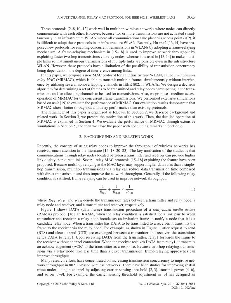
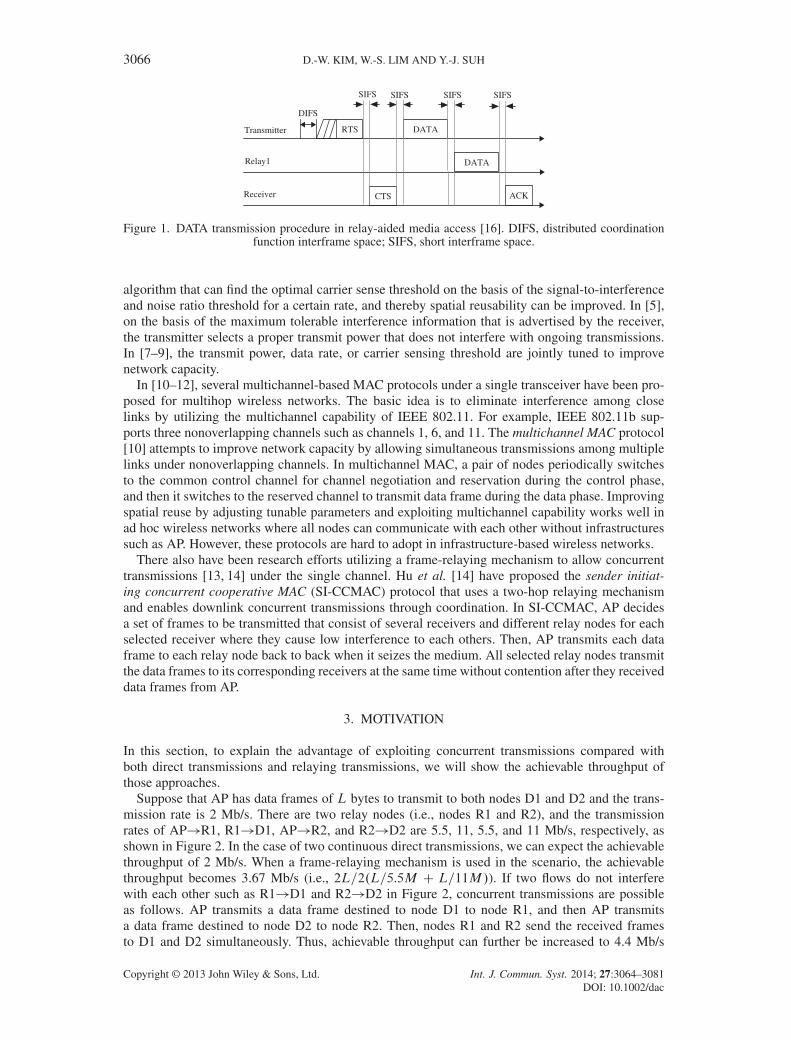
Figure 1 shows DATA (data frame) transmission procedure of a relay-aided media access(RAMA) protocol [16]. In RAMA, when the relay condition is satisfied for a link pair betweentransmitter and receiver, a relay node broadcasts an invitation frame to notify a node that it is acandidate relay node. When a transmitter has DATA to be transmitted to a receiver, it transmits theframe to the receiver via the relay node. For example, as shown in Figure 1, after request to send(RTS) and clear to send (CTS) are exchanged between a transmitter and receiver, the transmittersends DATA to relay1. Upon receiving DATA from the transmitter, relay1 forwards the frame tothe receiver without channel contention. When the receiver receives DATA from relay1, it transmitsan acknowledgement (ACK) to the transmitter as a response. Because two-hop relaying transmis-sions via a relay node take less time than a direct transmission, frame-relaying approaches canimprove throughput.
Many research efforts have concentrated on increasing transmission concurrency to improve net-work throughput in 802.11-based wireless networks. There have been studies for improving spatialreuse under a single channel by adjusting carrier sensing threshold [2, 3], transmit power [4–6],and so on [7–9]. For example, the carrier sensing threshold adjustment in [3] has designed an
Copyright © 2013 John Wiley & Sons, Ltd. Int. J. Commun. Syst. 2014; 27:3064–3081DOI: 10.1002/dac
3066 D.-W. KIM, W.-S. LIM AND Y.-J. SUH
Transmitter
Relay1
Receiver
RTS
DIFS
SIFS SIFS SIFS
CTS
DATA
DATA
SIFS
ACK
Figure 1. DATA transmission procedure in relay-aided media access [16]. DIFS, distributed coordinationfunction interframe space; SIFS, short interframe space.
algorithm that can find the optimal carrier sense threshold on the basis of the signal-to-interferenceand noise ratio threshold for a certain rate, and thereby spatial reusability can be improved. In [5],on the basis of the maximum tolerable interference information that is advertised by the receiver,the transmitter selects a proper transmit power that does not interfere with ongoing transmissions.In [7–9], the transmit power, data rate, or carrier sensing threshold are jointly tuned to improvenetwork capacity.
In [10–12], several multichannel-based MAC protocols under a single transceiver have been pro-posed for multihop wireless networks. The basic idea is to eliminate interference among closelinks by utilizing the multichannel capability of IEEE 802.11. For example, IEEE 802.11b sup-ports three nonoverlapping channels such as channels 1, 6, and 11. The multichannel MAC protocol[10] attempts to improve network capacity by allowing simultaneous transmissions among multiplelinks under nonoverlapping channels. In multichannel MAC, a pair of nodes periodically switchesto the common control channel for channel negotiation and reservation during the control phase,and then it switches to the reserved channel to transmit data frame during the data phase. Improvingspatial reuse by adjusting tunable parameters and exploiting multichannel capability works well inad hoc wireless networks where all nodes can communicate with each other without infrastructuressuch as AP. However, these protocols are hard to adopt in infrastructure-based wireless networks.
There also have been research efforts utilizing a frame-relaying mechanism to allow concurrenttransmissions [13, 14] under the single channel. Hu et al. [14] have proposed the sender initiat-ing concurrent cooperative MAC (SI-CCMAC) protocol that uses a two-hop relaying mechanismand enables downlink concurrent transmissions through coordination. In SI-CCMAC, AP decidesa set of frames to be transmitted that consist of several receivers and different relay nodes for eachselected receiver where they cause low interference to each others. Then, AP transmits each dataframe to each relay node back to back when it seizes the medium. All selected relay nodes transmitthe data frames to its corresponding receivers at the same time without contention after they receiveddata frames from AP.
3. MOTIVATION
In this section, to explain the advantage of exploiting concurrent transmissions compared withboth direct transmissions and relaying transmissions, we will show the achievable throughput ofthose approaches.
Suppose that AP has data frames of L bytes to transmit to both nodes D1 and D2 and the trans-mission rate is 2 Mb/s. There are two relay nodes (i.e., nodes R1 and R2), and the transmissionrates of AP!R1, R1!D1, AP!R2, and R2!D2 are 5.5, 11, 5.5, and 11 Mb/s, respectively, asshown in Figure 2. In the case of two continuous direct transmissions, we can expect the achievablethroughput of 2 Mb/s. When a frame-relaying mechanism is used in the scenario, the achievablethroughput becomes 3.67 Mb/s (i.e., 2L=2.L=5.5M C L=11M/). If two flows do not interferewith each other such as R1!D1 and R2!D2 in Figure 2, concurrent transmissions are possibleas follows. AP transmits a data frame destined to node D1 to node R1, and then AP transmitsa data frame destined to node D2 to node R2. Then, nodes R1 and R2 send the received framesto D1 and D2 simultaneously. Thus, achievable throughput can further be increased to 4.4 Mb/s
Copyright © 2013 John Wiley & Sons, Ltd. Int. J. Commun. Syst. 2014; 27:3064–3081DOI: 10.1002/dac

A MULTICHANNEL RELAY MAC PROTOCOL FOR IEEE 802.11 WIRELESS LANS 3067
AP
D1R1
R2
D2
11 Mbps
D3
Figure 2. An example scenario to show the advantage of using concurrent transmission. AP, access point.
(i.e., 2L=.L=5.5M C L=5.5M C L=11M/) with the help of transmission concurrency. Althoughcontrol overhead can decrease the actual throughput, we can still expect improved throughput, if theframe size is not too small [13, 14].
However, using concurrent transmissions in a single channel has several limitations as follows.First, AP should be aware of the interference information of all possible links in the network. It ispossible for AP to know the interference map among all links in the network if each node notifies APof its perceived interference level from all the other nodes. This may cause much control overhead.Second, the AP has difficulty maintaining the accurate interference level of each node experiencedby the other nodes in mobile scenarios. Another limitation of the approach is the possibility of trans-mission concurrency being dependent on the degree of interference among nodes. As an example,if two links (links R1!D1 and R2!D2 in Figure 2) interfere with each other, both links cannotbe activated simultaneously. To handle this, we propose MRMAC, which utilizes nonoverlappingchannels to eliminate interference so that it allows multiple frames to be transmitted simultaneouslywithout interference.
4. MULTICHANNEL RELAY MEDIUM ACCESS CONTROL PROTOCOL
In this section, we describe the operation of the proposed protocol called MRMAC, which exploitsthe frame relay mechanism and nonoverlapping channels to enable interference-free concurrenttransmissions in a WLAN. First, we explain the system model of MRMAC. Next, we will describethe relay node notification procedures and the maintenance of the relay nodes at both AP and othernodes. Then, we will explain the decision algorithm performed in AP to prepare a set of framesto be transmitted at the channel access. After explaining the decision algorithm, we describe themedium access operation among AP, relay nodes, and receivers. Last, we explain the effect of chan-nel switching delay and throughput analysis and discuss some issues considered for incorporatingMRMAC into IEEE 802.11.
4.1. System model
First, we explain the system model in MRMAC. We assume that a single AP and several nodesexist in an infrastructure WLAN. Also, there is no energy constraint of node, node failure, and net-work partitioning. But we assume that frame loss may occur because of either collision by hiddennode or channel error. And all nodes are working on the distributed coordination function (DCF)-mode-based IEEE 802.11 and can overhear the ongoing frames even if they are encoded. AP takesresponsibility for transmitting frames to the intended receivers, whereas the other nodes transmit
Copyright © 2013 John Wiley & Sons, Ltd. Int. J. Commun. Syst. 2014; 27:3064–3081DOI: 10.1002/dac

3068 D.-W. KIM, W.-S. LIM AND Y.-J. SUH
their frames toward AP. The nodes except AP can act as relay nodes for some links. Last, AP canobtain the information about unused or rarely used channel by adjacent APs.
4.2. Relay node notification and maintenance
In MRMAC, nodes can act as relay nodes if some conditions are satisfied. If those nodes exist,they will perform relay node notification procedure periodically to notify AP about the informationthat it is a candidate relay node for some links. AP maintains the received information in a table,referred to as RelayTable, and uses it when executing the decision algorithm, explained in the nextsubsection.
Now, we explain how nodes can know that it can be a relay node. In 802.11-based wireless net-works, nodes between a transmitter and receiver can overhear ongoing frames (e.g., DATA or ACK)between them. When a node overhears a data frame and if it can decode that frame, it can knowthe transmission rate between the transmitter and receiver from the physical layer convergence pro-tocol (PLCP) header of a data frame (i.e., RS,D) and the MAC addresses of both the transmitterand receiver from the MAC header of the frame. Also, the node can estimate the channel conditionbetween the transmitter and itself by measuring the signal strength of the received data frame. Fromthe signal strength, the node determines the supportable transmission rate between the transmitterand itself (i.e.,RS,R) similar to that in [24]. Specifically, a node compares the received signal strengthwith the threshold value, which can satisfy a required bit error rate for the each modulation scheme.By doing so, it can choose the most proper transmission rate for each node. When the intendedreceiver of a data frame decodes the data frame successfully, it will send ACK as a response aftera short interframe space (SIFS). Thus, although ACK has no transmitter’s MAC address field, thenode overhearing both ACK and a data frame can infer the MAC address of the transmitter. Fromthe received signal strength of ACK, the node overhearing ACK can choose the transmission ratebetween itself and the receiver (i.e., RR,D). In addition, both RTS and CTS can be also used tomeasure channel conditions.
Once a node acquires RS,D, RS,R, and RR,D, it determines whether it can be a relay node or not fordata transmissions between the transmitter and receiver by checking the condition in Equation (1).If the condition is satisfied, it can act as a candidate relay node for the link pair between the trans-mitter and receiver. The candidate relay node stores the corresponding information in a table thathas five fields: MAC addresses of the transmitter and receiver, RS,R, RR,D, and RS,D. A candidaterelay node prepares an advertisement message that contains its table information and forwards it toAP periodically.
When receiving the advertisement message, AP stores the corresponding information in theRelayTable, which has five fields for each entry: STA ID, RESTA ID, RS,R, RR,D, and RS,D. STA IDand RESTA ID denote the MAC addresses of the receiver and relay nodes, respectively. The tablehas one or more entries for a STA ID, which means that one or more nodes can be candidate relaynodes for the receiver. AP maintains the latest RelayTable information to avoid abnormal opera-tions. For this, whenever receiving advertisement messages from candidate relay nodes or receivingcontrol frames (such as CTS and ACK) from some nodes, AP updates the entries associated withthe received messages in its RelayTable. Also, for stale information to be dealt with, each entry inthe table is maintained by a timer. If AP cannot receive any information for a certain entry until theexpiration of the timer, it deletes the entry from the RelayTable.
Similar to the AP, nodes have staRelayTable, which is used to find relay nodes for faster transmis-sion of their own uplink frames. When a node overhears an advertisement message from a certainnode, it checks its MAC address in the message. If it is found, the node stores the associated infor-mation in its staRelayTable, which has four fields for each entry: RESTA ID, RS,R, RR,D, and RS,D.Nodes maintain their table with the latest information by a timer similar to APs.
4.3. Decision algorithm
In MRMAC, before the channel access, AP executes the decision algorithm consisting of both theframe selection and the channel assignment, which selects a set of frames and allocates channels tothose frames, respectively.
Copyright © 2013 John Wiley & Sons, Ltd. Int. J. Commun. Syst. 2014; 27:3064–3081DOI: 10.1002/dac

A MULTICHANNEL RELAY MAC PROTOCOL FOR IEEE 802.11 WIRELESS LANS 3069
Figure 3. Frame selection part in decision algorithm. DCF, distributed coordination function; MRMAC,multichannel relay medium access control.
Table I. Notations used in multichannel relay medium access control.
Notations Definitions
m The number of available nonoverlapping channelsOq A list of frames in the access point’s queueOs A list of selected frames to be transmitted in OqOd A list of the receiver address for each frame in OsOr A list of the selected relay node address for each frame in Osj Oxj The number of elements in Ox (x 2 {q, s, d , r})Ox.i/ i th element in Oxd Oq.i/ The receiver of frame Oq.i/
rj
Oq.i/A candidate relay node j of frame Oq.i/
L Oq.i/ The packet length of frame Oq.i/
First, we explain the frame selection algorithm where m is the number of available nonoverlap-ping channels. The frame selection algorithm is used to determine the following: (i) a set of framesto be transmitted; and (ii) a set of nodes acting as a relay node for each selected frame. Figure 3shows the details of frame selection, and Table I shows the notations used in the decision algorithm.For the while loop (steps 5–20), AP checks frames in the queue one by one until either no moreframes exist in the queue or the number of selected frames is greater than m. We limit jOsj to m toguarantee interference-free transmissions among selected frames.
In each iteration, AP first checks whether the receiver for the i th frame of the queue is the sameas either the receiver or its relay node for each of the selected frames or not (step 7). The reason forthe step is to make several disjoint links for enabling concurrent transmissions among them. If step7 is satisfied, the AP examines its RelayTable by using the receiver of the i th frame as the indexto find a possible relay node (step 8). The candidate relay nodes should satisfy the condition that
Copyright © 2013 John Wiley & Sons, Ltd. Int. J. Commun. Syst. 2014; 27:3064–3081DOI: 10.1002/dac
3070 D.-W. KIM, W.-S. LIM AND Y.-J. SUH
they are neither the receivers nor the relay nodes for the selected frames (step 9). Then, a node withminimum TMRMAC among candidate relay nodes is selected as a relay node for the frame (step 11).TMRMAC.L,R,D/ means the time required for transmitting a frame of L bytes to receiver D viarelay node R, which is expressed as
TMRMAC.L,R,D/D T .L,RAP,R/C T .L,RR,D/C 3tSIFSC 2TACK (2)
where TACK is the transmission time for ACK, T .L,RAP,R/ is the transmission time of a data framewithRAP,R (the transmission rate between AP and relay nodeR), T .L,RR,D/ is the transmission timeof a data frame with RR,D (the transmission rate between relay node R and receiver D). Then, APcompares the minimum TMRMAC.L,R,D/ with TDCF.L,D/. TDCF.L,D/ means the time requiredfor transmitting a frame of L bytes to receiver D directly and is expressed as
TDCF.L,D/D T .L,RAP,D/C tSIFSC TACK (3)
where T .L,RAP,D/ is the transmission time of a data frame with RAP,D (the transmission ratebetween AP and receiver D). If TMRMAC is less than TDCF, the frame is inserted into Os, and thereceiver and its selected relay node are also inserted into Od and Or , respectively (steps 15 and 16).Then, if jOsj is smaller than m, AP goes to step 6 and executes the algorithm again with the nextframe in the Oq.
If there is no candidate relay node that satisfies steps 9 and 10 or if the minimum TMRMAC is largerthan TDCF, the next step is as follows. If the frame is the first frame in the queue (i.e., i equals 0 instep 17), AP stops the frame selection part. Otherwise, AP continues the frame selection algorithmfor the next frame of Oq (step 6). As results of the frame selection algorithm, Os and Or can be obtainedby AP, which will be used in the medium access operation. To reduce the processing time, AP onlykeeps a pointer of each selected frame in Os instead of a copy for each one.
After executing the frame selection algorithm, AP performs the channel assignment algorithm,which allocates a different channel to each selected frame. The allocated channel is used to transmita data frame between the receiver of the frame and its relay node. There are two types of channelsin MRMAC: a primary channel and a secondary channel. The primary channel is a main channelused for transmissions between AP and its associated nodes in a WLAN. The secondary chan-nel is any channel except the primary channel, and AP exploits unused or rarely used channels assecondary channels.
When the number of selected frames (i.e., jOsj) is 1, AP allocates the frame to the primary channel.Otherwise (i.e., jOsj > 2), AP allocates a different nonoverlapping channel to each of the selectedframes as follows. AP allocates the primary channel to a frame that has the maximum T .L,RR,D/
value in Os, whereas the other channels (i.e., secondary channel) are assigned randomly to the remain-ing frames in Os. Then, AP sorts both Os and Or such that the frame using the primary channel isserved last, whereas the others are served randomly. The reason why the frame with the maximumT .L,RR,D/ value is served last is to allow nodes using a secondary channel to participate in thenext channel contention in time. Suppose that the data transmission under the primary channel isterminated but the data transmission under a secondary channel is not terminated yet. In this case,the nodes using the secondary channel cannot participate in the next channel contention in time.To avoid such problem, AP allocates a frame with the maximum T .L,RR,D/ value to the primarychannel where the frame is transmitted at last.
In a decision algorithm, if the first frame in AP’s queue is able to be transmitted via relay nodes,the frame selection part could choose multiple frames to be relayed regardless of their queue posi-tions. Thus, some relay frames arriving in the AP’s queue later than some direct transmission framesmight be served in advance. However, because AP always transmits the first frame of the queue ina channel access, the serving opportunity to be transmitted is the same between those frames. Thecomputational complexity of the decision algorithm depending on j Oqj, N , and m is represented asO(j Oqj �N �m2CjOsj � log jOsj)= O(j Oqj �N �m2), where N is the number of elements in the RelayTable.Because the complexity is relatively small, it is possible for AP to finish the execution of the deci-sion algorithm before the backoff expiration. However, if AP does not complete the execution of thealgorithm by the end of backoff time, it will do the backoff procedure again.
Copyright © 2013 John Wiley & Sons, Ltd. Int. J. Commun. Syst. 2014; 27:3064–3081DOI: 10.1002/dac
A MULTICHANNEL RELAY MAC PROTOCOL FOR IEEE 802.11 WIRELESS LANS 3071
Frame
ControlDuration
TX
num (j)
Relay node
address
Bytes: 2 2 6 1
TX
list1...
TX
list jFCS
Bcast
address
Receiver
address
Channel
number
13 4
6 1
13
Bytes: 6
6
AP
address
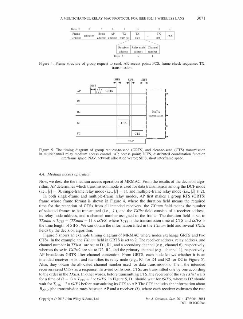
Figure 4. Frame structure of group request to send. AP, access point; FCS, frame check sequence; TX,transmission.
AP
R1
R2
GRTS
D1
D2
CTS
NAV
DIFS
SIFS
CTS
SIFS SIFS
DATA
transmission
Figure 5. The timing diagram of group request-to-send (GRTS) and clear-to-send (CTS) transmissionin multichannel relay medium access control. AP, access point; DIFS, distributed coordination function
interframe space; NAV, network allocation vector; SIFS, short interframe space.
4.4. Medium access operation
Now, we describe the medium access operation of MRMAC. From the results of the decision algo-rithm, AP determines which transmission mode is used for data transmission among the DCF mode(i.e., jOsj D 0), single-frame relay mode (i.e., jOsj D 1), and multiple-frame relay mode (i.e., jOsj > 2).
In both single-frame and multiple-frame relay modes, AP first makes a group RTS (GRTS)frame whose frame format is shown in Figure 4, where the duration field means the requiredtime for the reception of CTSs from all intended receivers, the TXnum field means the numberof selected frames to be transmitted (i.e., jOsj), and the TXlist field consists of a receiver address,its relay node address, and a channel number assigned to the frame. The duration field is set toTXnum � TCTS C .TXnumC 1/ � tSIFS, where TCTS is the transmission time of CTS and tSIFS isthe time length of SIFS. We can obtain the information filled in the TXnum field and several TXilstfields by the decision algorithm.
Figure 5 shows an example timing diagram of MRMAC where nodes exchange GRTS and twoCTSs. In the example, the TXnum field in GRTS is set to 2. The receiver address, relay address, andchannel number in TXlist1 are set to D1, R1, and a secondary channel (e.g., channel 6), respectively,whereas those in TXlist2 are set to D2, R2, and the primary channel (e.g., channel 1), respectively.AP broadcasts GRTS after channel contention. From GRTS, each node knows whether it is anintended receiver or not and identifies its relay node (e.g., R1 for D1 and R2 for D2 in Figure 5).Also, they obtain the allocated channel number used for data transmissions. Then, the intendedreceivers send CTSs as a response. To avoid collisions, CTSs are transmitted one by one accordingto the order in the TXlist. In other words, before transmitting CTS, the receiver of the i th TXlist waitsfor a time of .i � 1/� TCTSC i � tSIFS. In Figure 5, D1 should wait for tSIFS, whereas D2 shouldwait for TCTSC2�tSIFS before transmitting its CTS to AP. The CTS includes the information aboutRAP,D (the transmission rates between AP and a receiver D), where each receiver estimates the rate
Copyright © 2013 John Wiley & Sons, Ltd. Int. J. Commun. Syst. 2014; 27:3064–3081DOI: 10.1002/dac

3072 D.-W. KIM, W.-S. LIM AND Y.-J. SUH
AP DATA1
R1
D1
ACK
SIFS SIFS SIFS
ACK
DATA1
Figure 6. The timing diagram of DATA transmission in a single-frame relay mode. ACK, acknowledgement;AP, access point; SIFS, short interframe space.
from the channel condition of the received GRTS. Through overhearing CTS sent by a receiver, theselected relay node for the receiver estimates RR,D (the transmission rate between the receiver andthe relay node). If one or more CTSs during the expected time are received, the AP starts data frametransmission procedures. It removes the corresponding element in Os and Or about receivers that didnot send CTSs. If AP did not receive any CTSs from intended receivers, it removes all elements inOs and Or and stops the data frame transmission procedures.
Figure 6 illustrates the transmission procedure of the single-frame relay mode, which is similar tothe operation of existing frame-relaying mechanisms [15–18]. After control frames are exchangedbetween AP and D1, AP gets DATA1 from Os and transmits it to R1. The duration field is set totSIFS C TACK, which is the time required for the subsequent ACK reception. When R1 receivesDATA1 successfully, it sends ACK as a response after tSIFS. When AP receives ACK from R1, itdeletes DATA1 in its queue (i.e., Oq). Otherwise, AP will retransmit the frame. After transmittingACK, R1 forwards DATA1 to the intended receiver (i.e., D1). Last, D1 responds to R1 with ACK.
Now, we explain the medium access operation in the multiple-frame relay mode when jOsj is m(m > 2). After GRTS and m CTSs are exchanged among AP and its selected receivers, AP obtainsthe first data frame from Os and transmits it to the selected relay node for the frame. If AP receivesACK from the relay node that transmits ACK as a response, it removes the transmitted data framein its queue (i.e., Oq). Otherwise, AP will retransmit the frame at the next channel access. Whilewaiting for the ACK reception, AP prepares for the transmission of the next frame in Os in advance.Once the AP receives the ACK, it sends the next frame consecutively to its selected relay nodeafter tSIFS, which is similar to the transmission opportunity operation in IEEE 802.11e [25]. APcontinues back-to-back transmissions until the number of transmission trials is equal to jOsj.
Meanwhile, when a relay node receives a data frame from AP successfully, if the allocated chan-nel is not the primary channel, it switches to the allocated channel right after transmitting ACK toAP. And the intended receiver switches to the channel for the communication with the relay nodeonly if the relay node successfully receives a data frame from AP. When the channel is idle duringtDIFS, which is the time length of the DCF interframe space (DIFS), the relay node starts exchang-ing DATA and ACK with the intended receiver. It removes the data frame when receiving ACK fromthe receiver as a response. Once frames are exchanged, they return to the primary channel and waitto participate in the next channel contention. Now, let us examine how the receiver checks whetherthe relay node receives a data frame successfully or not when determining channel switch. It is pos-sible if the receiver overhears both a data frame and an ACK frame between AP and the relay node.However, the data frame is transmitted to the relay node with a rate higher than can be supportedby the receiver, so the receiver cannot overhear the frame. Also, because ACK has no transmissionfield, although the receiver can overhear ACK, it cannot know whether the ACK frame is sent byits relay node or not. To deal with this problem, we modify ACK to include the MAC address ofthe transmitter.
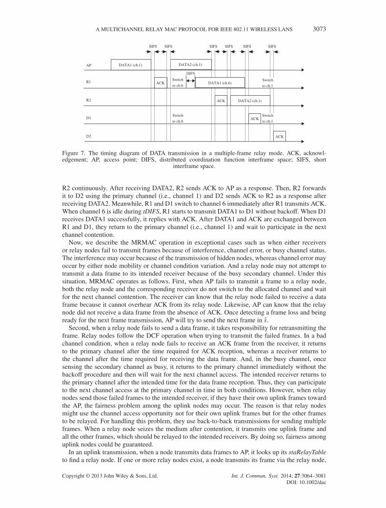
As an example, we explain the transmission procedure of the multiple-frame relay mode whenjOsj is 2, which is shown in Figure 7. After GRTS and CTSs are exchanged among AP, D1, and D2in Figure 5, AP extracts DATA1 from Os and transmits it to R1. If AP receives ACK from R1 as aresponse, it removes the DATA1 in its queue. Then, AP obtains DATA2 from Os and transmits it to
Copyright © 2013 John Wiley & Sons, Ltd. Int. J. Commun. Syst. 2014; 27:3064–3081DOI: 10.1002/dac
A MULTICHANNEL RELAY MAC PROTOCOL FOR IEEE 802.11 WIRELESS LANS 3073
AP DATA1 (ch.1)
R1
R2
D1
D2
ACK
Switch
to ch.6
Switch
to ch.6
DIFS
DATA1 (ch.6)
DATA2 (ch.1)
Switch
to ch.1
Switch
to ch.1
ACK
ACK
ACK
SIFS SIFS SIFS SIFS SIFS SIFS
DATA2 (ch.1)
Figure 7. The timing diagram of DATA transmission in a multiple-frame relay mode. ACK, acknowl-edgement; AP, access point; DIFS, distributed coordination function interframe space; SIFS, short
interframe space.
R2 continuously. After receiving DATA2, R2 sends ACK to AP as a response. Then, R2 forwardsit to D2 using the primary channel (i.e., channel 1) and D2 sends ACK to R2 as a response afterreceiving DATA2. Meanwhile, R1 and D1 switch to channel 6 immediately after R1 transmits ACK.When channel 6 is idle during tDIFS, R1 starts to transmit DATA1 to D1 without backoff. When D1receives DATA1 successfully, it replies with ACK. After DATA1 and ACK are exchanged betweenR1 and D1, they return to the primary channel (i.e., channel 1) and wait to participate in the nextchannel contention.
Now, we describe the MRMAC operation in exceptional cases such as when either receiversor relay nodes fail to transmit frames because of interference, channel error, or busy channel status.The interference may occur because of the transmission of hidden nodes, whereas channel error mayoccur by either node mobility or channel condition variation. And a relay node may not attempt totransmit a data frame to its intended receiver because of the busy secondary channel. Under thissituation, MRMAC operates as follows. First, when AP fails to transmit a frame to a relay node,both the relay node and the corresponding receiver do not switch to the allocated channel and waitfor the next channel contention. The receiver can know that the relay node failed to receive a dataframe because it cannot overhear ACK from its relay node. Likewise, AP can know that the relaynode did not receive a data frame from the absence of ACK. Once detecting a frame loss and beingready for the next frame transmission, AP will try to send the next frame in Os.
Second, when a relay node fails to send a data frame, it takes responsibility for retransmitting theframe. Relay nodes follow the DCF operation when trying to transmit the failed frames. In a badchannel condition, when a relay node fails to receive an ACK frame from the receiver, it returnsto the primary channel after the time required for ACK reception, whereas a receiver returns tothe channel after the time required for receiving the data frame. And, in the busy channel, oncesensing the secondary channel as busy, it returns to the primary channel immediately without thebackoff procedure and then will wait for the next channel access. The intended receiver returns tothe primary channel after the intended time for the data frame reception. Thus, they can participateto the next channel access at the primary channel in time in both conditions. However, when relaynodes send those failed frames to the intended receiver, if they have their own uplink frames towardthe AP, the fairness problem among the uplink nodes may occur. The reason is that relay nodesmight use the channel access opportunity not for their own uplink frames but for the other framesto be relayed. For handling this problem, they use back-to-back transmissions for sending multipleframes. When a relay node seizes the medium after contention, it transmits one uplink frame andall the other frames, which should be relayed to the intended receivers. By doing so, fairness amonguplink nodes could be guaranteed.
In an uplink transmission, when a node transmits data frames to AP, it looks up its staRelayTableto find a relay node. If one or more relay nodes exist, a node transmits its frame via the relay node,
Copyright © 2013 John Wiley & Sons, Ltd. Int. J. Commun. Syst. 2014; 27:3064–3081DOI: 10.1002/dac
3074 D.-W. KIM, W.-S. LIM AND Y.-J. SUH
which is similar to the operation of a single-frame relay mode in Figure 6. First, a node exchangesGRTS and CTS with AP. Then, it sends a data frame to the selected relay node. After responding tothe node, the relay node forwards the received frame to AP. If there is no relay node, the node willsend the frame to AP directly.
4.5. Effect of switching delay
In the multiple-frame relay mode of MRMAC, a receiver and relay node switch to a secondarychannel, exchange a data frame between them, and then return to the primary channel. Becausethese nodes have to switch channels twice per frame, someone may think that the switching delay,the time elapsed for switching channels, could degrade the network performance.
However, the impact of switching delay on network performance is negligible. We explain itwith an example shown in Figure 7. In the example, we assume that the length of both DATA1and DATA2 is L. In the figure, the operation of DATA1 transmission between R1 and D1 occursconcurrently with the operation of DATA2 transmission among AP, R2, and D2 using differentchannels. The required time for exchanging a data frame between R1 and D1 can be calcu-lated as T1 D 2ı C tDIFS C T .L,RR1,D1/ C tSIFS C TACK, where ı is the switching delay.Also, we can calculate that the required time for exchanging a data frame between AP and D2is T 2 D TMRMAC.L,R2,D2/ from Equation (2). If R1 and D1, which use the secondary chan-nel, return to the primary channel before the end of DATA2 transmission between R2 and D2(i.e., T1 6 T 2), the impact of the switching delay on network performance can be ignored.From the decision algorithm, we know that the frame with the largest T .L,RR,D/ value is servedlast, and thus T .L,RR2,D2/ is greater than or equal to T .L,RR1,D1/. Let us consider the worstcase where T .L,RR2,D2/ is equal to T .L,RR1,D1/. In this case, T1 6 T 2 can be expressed as2ı 6 T .L,RAP,R2/C 2tSIFSC TACK � tDIFS. Then, we can derive it as ı 6 TACK approximatelybecause T .L,RAP,R2/ is greater than .TACKC 3tSIFS/ always. Thus, if ı is smaller than or equal toTACK, the performance degradation by ı does not occur because T1 is smaller than T 2 always in thecondition. For example, ı in off-the-shelf 802.11b, hardware is about 150 to 200 �s [26], but TACK isabout 300 �s.
4.6. Throughput analysis
In this section, we derive the maximum throughput of MRMAC in a given network where there existm available channels (i.e., one primary channel and (m�1) secondary channels) and several down-link flows of L byte size with average R Mb/s. For simplicity, we assume that there are a sufficientnumber of relay nodes (named as R1, R2, and so on) so that m back-to-back transmissions alwayscould be initiated. Also, we assume the ideal channel condition (i.e., no hidden terminals), no uplinkflows (i.e., no collisions), and saturated traffic for each flow. Last, we ignore the processing delay ofthe decision algorithm.
In these circumstances, becausem frames are transmitted in a single-channel access in MRMAC,the MRMAC’s expected throughput can be estimated as
ETMRMAC Dm �L � 8
tDIFSC tBackoffC TMRMAC.m/(4)
where tBackoff is the average time spent for backoff (i.e., CWmin=2 � tSlotTime in which CWmin
is the value for the minimum contention window) and TMRMAC.m/ is the total time requiredfor sending m data frames. We can calculate TMRMAC.m/ as TGRTS.m/ C m � .tSIFS C TCTS/ C˙miD1.tSIFS C T .L,RAP,Ri/ C tSIFS C TACK/ C tSIFS C T .L,R0R,D/ C tSIFS C TACK, where
TGRTS.m/ is the transmission time for GRTS with information about m frames and R0R,D is theminimum transmission rate of m transmission rates between selected relay nodes and receivers.If Rr1 is the average transmission rate between AP and selected relay nodes and Rr2 is theaverage rate of the minimum transmission rates (i.e., R0R,D), TMRMAC.m/ could be expressed as
Copyright © 2013 John Wiley & Sons, Ltd. Int. J. Commun. Syst. 2014; 27:3064–3081DOI: 10.1002/dac
A MULTICHANNEL RELAY MAC PROTOCOL FOR IEEE 802.11 WIRELESS LANS 3075
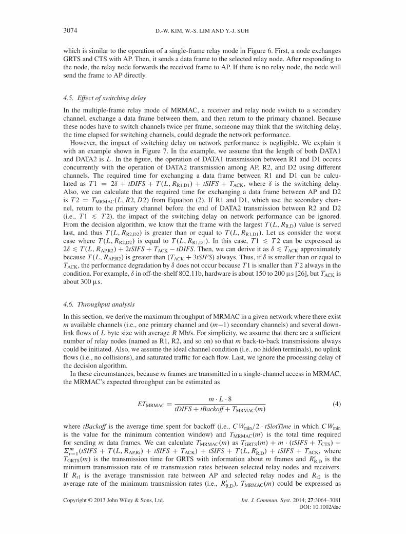
Figure 8. Throughput analysis of multichannel relay medium access control (MRMAC), relay-aidedmedia access (RAMA), distributed coordination function (DCF) with two-way handshake according to the
frame size.
TGRTS.m/ C m � TCTS C m � T .L,Rr1/ C T .L,Rr2/ C .m C 1/ � TACK C .3m C 2/ � tSIFS. In thesame manner, the expected throughputs of both RAMA and DCF with two-way handshake could beestimated easily.
Figure 8 shows the results of throughput analysis for MRMAC, RAMA, and DCF according todata sizes ranging from 400 to 2000 bytes. We set CWmin at 31, R at 2 Mb/s, Rr1 at 11 Mb/s, andRr2 at 5.5 Mb/s. Also, m is set to either 2 or 3. In the figure, ‘MRMAC-2ch’ denotes MRMAC pro-tocol with two channels and ‘MRMAC-3ch’ denotes MRMAC protocol with three channels. Theresults in the data size of lower than 400 bytes are not indicated in the figure because no gain isexpected by MRMAC and RAMA over DCF. Except in this case, we can see that MRMAC showsimproved performance over RAMA and DCF. Specifically, when the data size increases, MRMACshows much better improvement than other protocols. For example, when the data size is 600 bytes(or 2000 bytes), the aggregate throughput of MRMAC-2ch and MRMAC-3ch is about 7.4% and25.1% (26.1% and 48.9%) better than RAMA, respectively.
4.7. Discussion
Now, we examine some issues that should be considered for incorporating MRMAC into IEEE802.11. First, AP should implement the decision algorithm that selects multiple frames to be servedin a single-channel access. Second, the modifications in some frames (e.g., GRTS, ACK, and DATA)are required. GRTS, a new control frame, should be defined for initiating the medium access opera-tion for MRMAC where the frame format is shown in Figure 4. And ACK needs to be modified toinclude the MAC address of a transmitter. Also, when a transmitter sends DATA to be relayed to thecorresponding relay node, it should include the MAC address of the intended receiver in the DATA.For this, a transmitter exploits the reserved address 4 field in the MAC header. Last, nodes shouldmodify DCF operations so that they follow the MRMAC’s medium access operation.
Although these modifications make it difficult to adopt MRMAC in IEEE 802.11 standards, theseare not just a matter of MRMAC. Most of the relay-based MAC protocols [15–17] are also requiredto change the operation in IEEE 802.11 standards as well as to define some control frames to enablethe relay operation. Nevertheless, MRMAC has better throughput and delay performance than theother relay-based MAC protocols [15–17]. Now, we explain whether MRMAC can be integratedwith the practical relay MAC protocol such as [18] or not. Lim et al. [18] have proposed a practicalrelay MAC protocol using proxy nodes that act as a relay node. The approach does not need themodification of nodes, which is its main advantage when compared with the previous approaches[15–17], and thus is easy to deploy. However, because it requires new nodes (i.e., proxy node) sup-porting relay capability, it is not cost-effective. Unfortunately, MRMAC cannot adapt the approachbecause the nodes should obtain some information from GRTS such as channel information tochange its channel to a secondary channel.
Copyright © 2013 John Wiley & Sons, Ltd. Int. J. Commun. Syst. 2014; 27:3064–3081DOI: 10.1002/dac
3076 D.-W. KIM, W.-S. LIM AND Y.-J. SUH
5. PERFORMANCE EVALUATION
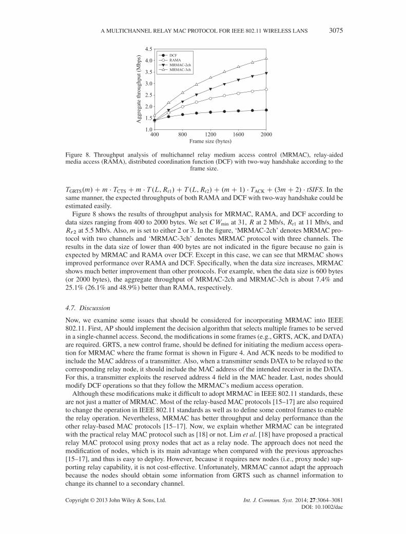
In this section, we evaluate the performance of MRMAC by using an ns-2 simulator [19] and com-pare it with DCF without RTS/CTS and RAMA [16], one of the representative frame-relayingprotocols. We assume that nodes can select the optimal rate according to the current channel condi-tion in DCF. Also, RAMA uses RTS and CTS exchange only when the relay transmission betweena transmitter and a receiver is enabled. In the direct transmission, RAMA follows DCF to reducecontrol overhead. And we do not compare MRMAC with SI-CCMAC [14] because SI-CCMAC hasdifficulty obtaining an interference map in the network in mobile environments. In our simulations,the two-ray path loss model is used as the radio propagation model and the random-way point mobil-ity model is used as the mobility model [27]. We set the nodes such that each has an IEEE 802.11binterface with IEEE 802.11b parameters shown in Table II. AP can use three nonoverlapping chan-nels that are not used by nearby APs; the queue size of AP is set to 100. The transmission power ofnodes is set to 0.001 W (i.e., 0 dBm), where the transmission range of the base rate (i.e., 1 Mb/s)with the power is about 340 m. Also, each relay candidate node sends advertisement messages toAP every 2 s.
In our simulation, we used both User Datagram Protocol (UDP) and Transfer Control Protocol(TCP) flows, and all nodes except AP become receivers of these flows. In UDP, AP generatesconstant-bit-rate traffic per node. We measured the performance of DCF, RAMA, and MRMACby varying the number of nodes and the traffic rate. In TCP, TCP NewReno is used, and the TCPframe size is set to 1024 bytes. We measured the TCP performance of the three protocols by varyingthe number of nodes. We measured aggregate throughput and delay in the case of UDP and aggre-gate throughput and round-trip time (RTT) in the case of TCP. The aggregate throughput is the totalsum of DATA delivered to receivers per second during the simulation time. The delay is defined asthe time difference between the time when a frame is inserted to the queue of a transmitter and thetime when the frame is delivered successfully to the intended receiver. RTT is defined as the timedifference between the time when the source node sends a TCP frame and the time when it receivesthe ACK of the frame.
5.1. User Datagram Protocol Performance according to the number of nodes
We observed the impact of the number of relay nodes on the UDP performance by varying thenumber of nodes except AP from 10 to 40. AP is in the center of a circle whose radius is 340 m,and all nodes move at a maximum speed of 5 m/s within the circle. AP generates UDP traffic witha constant bit rate of 1 Mb/s where the network is saturated and the number of downlink flows is
Table II. Simulation parameters
Parameters Values
Preamble length 144 bitsPLCP header length 48 bitsMAC header 272 bitsSlotTime 20 �sShort interframe space 10 �sDCF interframe space 50 �sRequest to send 352 �sClear to send 304 �sACK in DCF and relay MAC/ACK in MRMAC 304 �s/352 �sCWmin 31CWmax 1023Data rates 1, 2, 5.5, and 11 Mb/sChannel switching delay 224 �s
ACK, acknowledgement; DCF, distributed coordination function; MAC,medium access control; MRMAC, multichannel relay MAC.
Copyright © 2013 John Wiley & Sons, Ltd. Int. J. Commun. Syst. 2014; 27:3064–3081DOI: 10.1002/dac
A MULTICHANNEL RELAY MAC PROTOCOL FOR IEEE 802.11 WIRELESS LANS 3077
(a) (b)
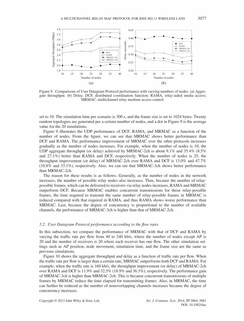
Figure 9. Comparisons of User Datagram Protocol performance with varying numbers of nodes. (a) Aggre-gate throughput. (b) Delay. DCF, distributed coordination function; RAMA, relay-aided media access;
MRMAC, multichannel relay medium access control.
set to 10. The simulation time per scenario is 300 s, and the frame size is set to 1024 bytes. Twentyrandom topologies are generated per a certain number of nodes, and a dot in Figure 9 is the averagevalue for the 20 simulations.
Figure 9 illustrates the UDP performance of DCF, RAMA, and MRMAC as a function of thenumber of nodes. From the figure, we can see that MRMAC shows better performance thanDCF and RAMA. The performance improvement of MRMAC over the other protocols increasesgradually as the number of nodes increases. For example, when the number of nodes is 10, theUDP aggregate throughput (or delay) achieved by MRMAC-2ch is about 9.1% and 35.4% (8.5%and 27.1%) better than RAMA and DCF, respectively. When the number of nodes is 25, thethroughput improvement (or delay) of MRMAC-2ch over RAMA and DCF is 13.0% and 47.7%(10.8% and 33.1%), respectively. Also, we can see that MRMAC-3ch shows better performancethan MRMAC-2ch.
The reason for these results is as follows. Generally, as the number of nodes in the networkincreases, the number of possible relay nodes also increases. Thus, because the number of relay-possible frames, which can be delivered to receivers via relay nodes increases, RAMA and MRMACoutperform DCF. Because MRMAC enables concurrent transmissions for those relay-possibleframes, the time required to transmit the same number of relay-possible frames in MRMAC isreduced compared with that required in RAMA, and thus RAMA shows worse performance thanMRMAC. Last, because the degree of concurrency is proportional to the number of availablechannels, the performance of MRMAC-3ch is higher than that of MRMAC-2ch.
5.2. User Datagram Protocol performance according to the flow rates
In this subsection, we compare the performance of MRMAC with that of DCF and RAMA byvarying the traffic rate per flow from 40 to 240 kb/s, where the number of nodes except AP is20 and the number of receivers is 20 where each receiver has one flow. The other simulation set-tings such as AP position, node movement, simulation time, and the frame size are the same asprevious simulations.
Figure 10 shows the aggregate throughput and delay as a function of traffic rate per flow. Whenthe traffic rate per flow is larger than a certain rate, MRMAC outperforms both DCF and RAMA. Forexample, when the traffic rate is 160 kb/s, the throughput improvement (or delay) of MRMAC-2chover RAMA and DCF is 11.9% and 32.5% (18.9% and 36.3%), respectively. The performance gainof MRMAC-3ch is higher than MRMAC-2ch. This is because concurrent transmissions of multipleframes by MRMAC reduce the time elapsed for transmitting frames. Also, in MRMAC, the timecan further be reduced as the number of nonoverlapping channels increases because the degree ofconcurrency increases.
Copyright © 2013 John Wiley & Sons, Ltd. Int. J. Commun. Syst. 2014; 27:3064–3081DOI: 10.1002/dac

3078 D.-W. KIM, W.-S. LIM AND Y.-J. SUH
(a) (b)
Figure 10. Comparisons of User Datagram Protocol performance with varying traffic rates per flow.(a) Aggregate throughput. (b) Delay. DCF, distributed coordination function; RAMA, relay-aided media
access; MRMAC, multichannel relay medium access control.
(a) (b)
Figure 11. Comparisons of Transfer Control Protocol performance with varying numbers of nodes.(a) Aggregate throughput. (b) Round-trip time. DCF, distributed coordination function; RAMA, relay-aided
media access; MRMAC, multichannel relay medium access control.
5.3. Transfer Control Protocol performance according to the number of nodes
Now, we evaluate the TCP performance of MRMAC according to the number of nodes to observe theimpact of the number of relay nodes. Simulation environments are the same as that in Section 5.1.Figure 11 shows the TCP performance of DCF, RAMA, and MRMAC. Similar to the simulationresults in Section 5.1, we can identify that MRMAC shows better throughput and RTT performancethan the other protocols for the same reason described in the previous subsections. For example,when the number of nodes is 20, the TCP aggregate throughput (or RTT) achieved by MRMAC-2chis about 11.3% and 40.6% (5.5% and 34.2%) better than RAMA and DCF, respectively. Also, wecan see that the performance gain of MRMAC-3ch is higher than that of MRMAC-2ch. For example,when there are 25 nodes, the TCP aggregate throughput (or RTT) by MRMAC-3ch is about 5.1%(8.7%) better than MRMAC-2ch.
5.4. User Datagram Protocol performance according to the number of contending nodes
Last, we look at how the UDP performance of three protocols changes as the contention levelincreases. For this, we vary the number of uplink nodes from 0 to 10 with a 200-kb/s traffic ratefor each uplink flow where the number of nodes except AP is 30. The uplink node is randomlyselected. The other simulation environments are the same as that in Section 5.1.
Copyright © 2013 John Wiley & Sons, Ltd. Int. J. Commun. Syst. 2014; 27:3064–3081DOI: 10.1002/dac

A MULTICHANNEL RELAY MAC PROTOCOL FOR IEEE 802.11 WIRELESS LANS 3079
Number of uplink nodes0 2 4 6 8 10
Dow
nlin
k th
roug
hput
(M
bps)
0.0
0.5
1.0
1.5
2.0
2.5
3.0
3.5DCFRAMAMRMAC-2chMRMAC-3ch
(a)
Number of uplink nodes0 2 4 6 8 10
Upl
ink
thro
ughp
ut (
Mbp
s)
0.0
0.4
0.8
1.2
1.6
2.0DCFRAMAMRMAC-2chMRMAC-3ch
(b)
Figure 12. Comparisons of User Datagram Protocol performance with varying numbers of uplink nodes.(a) Downlink throughput. (b) Uplink throughput. DCF, distributed coordination function; RAMA, relay-
aided media access; MRMAC, multichannel relay medium access control.
As shown in Figure 12, when the number of uplink nodes increases, the downlink throughputof three protocols gets worse because of the increased contention level but that of MRMAC stilloutperforms that of the others, similar to the previous simulation results. Furthermore, the morethe contention level imposes, the more is the downlink throughput gain in terms of the ratio ofMRMAC to the others. For example, when the number of uplink nodes is two, MRMAC-2ch pro-vides a higher downlink throughput than DCF and RAMA at about 49.7% and 9.8%, respectively.But, when the number of uplink nodes is 10, the downlink throughput achieved by MRMAC-2chis better than DCF and RAMA at about 79.3% and 66.2%, respectively. Also, we can see that theuplink throughput in MRMAC is higher than that of the others specially in the high-contention envi-ronments. MRMAC can provide a higher downlink throughput than the others with the help of theconcurrent transmissions of multiple downlink frames. Also, more time can be used for the uplinktraffic with the same reason, and thus, the uplink throughput of MRMAC is higher than that ofthe others.
6. CONCLUSION
In this paper, we proposed an enhanced MAC protocol called MRMAC that enhances the net-work throughput and delay of downlink transmissions in WLANs. The proposed MAC protocolhas been designed to enable interference-free concurrent transmissions by utilizing frame-relayingapproaches and several nonoverlapping channels in IEEE 802.11. MRMAC exploits frame-relayingtransmissions via relay nodes to allow transmission concurrency and multiple nonoverlapping chan-nels to enable interference-free transmissions among links. We designed a decision algorithm, whichconsists of a frame selection algorithm to select frames to be transmitted and relay nodes to partici-pate in the transmissions and a channel assignment algorithm to assign different channels for thoseframes. In addition, we proposed a medium access operation for concurrent data frame transmis-sions. Also, we explain the effect of switching delay, execute throughput analysis, and discuss someissues considered for incorporating MRMAC into IEEE 802.11. We showed the effectiveness of theproposed protocols via extensive simulation results.
ACKNOWLEDGEMENTS
This research was supported by a World Class University program funded by the Ministry of Educa-tion, Science, and Technology through the National Research Foundation of Korea (R31-10100). Thisresearch was supported by the MKE (The Ministry of Knowledge Economy), Korea, under the ITRC
Copyright © 2013 John Wiley & Sons, Ltd. Int. J. Commun. Syst. 2014; 27:3064–3081DOI: 10.1002/dac

3080 D.-W. KIM, W.-S. LIM AND Y.-J. SUH
(Information Technology Research Center) support program supervised by the NIPA (National IT Indus-try Promotion Agency) (NIPA-2012-H0301-12-3002). This work was supported by a National ResearchFoundation of Korea (NRF) grant funded by the Korean government (MEST) (2011-0029034).
REFERENCES
1. IEEE 802.11-2007. IEEE Standard—part 11: wireless LAN medium access control and physical layer specifications,June 2007.
2. Yang X, Vaidya NH. On the physical carrier sense in wireless ad hoc networks. Proceedings of IEEE INFOCOM,Miami, FL, USA, March 2005; 2525–2535.
3. Zhu J, Guo X, Yang LL, Conner WS. Leveraging spatial reuse in 802.11 mesh networks with enhanced physicalcarrier sensing. Proceedings of IEEE ICC, Paris, France, June 2004; 4004–4011.
4. Muqattash A, Krunz M. Power controlled dual channel (PCDC) medium access protocol for wireless ad hocnetworks. Proceedings of IEEE INFOCOM, San Francisco, California, USA, March 2003; 470–480.
5. Muqattash A, Krunz M. A single-channel solution for transmission power control in wireless ad hoc networks.Proceedings of ACM MobiHoc, Tokyo, Japan, May 2004; 210–221.
6. Monks JP, Bharghavan V, Mei W, Hwu W. A power controlled multiple access protocol for wireless packet networks.Proceedings of IEEE INFOCOM, Anchorage, Alaska, USA, April 2001; 219–228.
7. Akella A, Judd G, Steenkiste P, Seshan S. Self management in chaotic wireless deployments. Proceedings of ACMMobiCom, Cologne, Germany, August 2005; 185–199.
8. Kim TS, Lim H, Hou JC. Understanding and improving the spatial reuse in multihop wireless networks. IEEETransactions on Mobile Computing 2008; 7(10):1200–1212.
9. Wang JT. Joint rate regulation and power control for cochannel interference limited wireless networks. WileyInternational Journal of Communication Systems 2011; 24(8):967–977.
10. So J, Vaidya N. Multi-channel MAC for ad hoc networks, handling multi-channel hidden terminals using a singletransceiver. Proceedings of ACM MobiHoc, Tokyo, Japan, May 2004; 222–233.
11. Bahl P, Chandra R, Dunagan J. SSCH: slotted seeded channel hopping for capacity improvement in IEEE 802.11ad-hoc wireless networks. Proceedings of ACM MobiCom, Philadelphia, PA, USA, September 2004; 216–230.
12. Kao HH, Wu PJ, Lee CN. Analysis and enhancement of multi-channel MAC protocol for ad hoc networks. WileyInternational Journal of Communication Systems 2011; 24(3):310–324.
13. Hu Z, Tham C-K. CCMAC: coordinated cooperative MAC for wireless LANs. Proceedings of ACM MSWiM,Vancouver, Canada, October 2008; 60–69.
14. Hu Z, Tham C-K. SI-CCMAC: sender initiating concurrent cooperative MAC for wireless LANs. Proceedings ofACM WiOpt, Seoul, Korea, June 2009; 1–10.
15. Zhu H, Coa G. rDCF: a relay-enabled medium access control protocol for wireless ad hoc networks. IEEETransactions on Mobile Computing 2006; 5(9):1201–1214.
16. Zou S-H, Li B, Wu H-T, Zhang Q, Zhu W-W. A relay aided media access (RAMA) protocol in multi-rate wirelessnetworks. IEEE Transactions on Vehicular Technology 2006; 55(5):1657–1667.
17. Liu P, Tao Z, Narayanan S, Korakis T, Panwar SS. CoopMAC: a cooperative MAC for wireless LANs. IEEE Journalon Selected Areas in Communications 2007; 25(2):340–354.
18. Lim WS, Kim DW, Suh YJ. PR-MAC: a practical approach for exploiting relay transmissions in multi-rate WLANs.IEEE Transactions on Wireless Communications 2010; 9(1):66–71.
19. NS Official Website. (Available from: http://www.isi.edu/nsnam/ns/).20. Liu W, Jin H, Wang X, Guizani M. A novel IEEE 802.11-based MAC protocol supporting cooperative communica-
tions. Wiley International Journal of Communication Systems 2011; 24(11):1480–1495.21. An D, Woo H, Yoon H, Yeom I. Enhanced cooperative communication MAC for mobile wireless networks. Elsevier
Computer Networks 2013; 57(1):99–116.22. Rui X, Hou J, Zhou L. Decode-and-forward with full-duplex relaying. Wiley International Journal of Communication
Systems 2012; 25(2):270–275.23. Xu W, Lin J, Niu K, He Z. Error performance for relaying protocols with multiple decode-and-forward relays. Wiley
International Journal of Communication Systems 2010; 23(8):1016–1040.24. Pavon JP, Choi S. Link adaptation strategy for IEEE 802.11 WLAN via received signal strength measurement.
Proceedings of IEEE ICC, Anchorage, Alaska, USA, May 2003; 1108–1113.25. IEEE 802.11e. Part 11: wireless medium access control (MAC) and physical layer (PHY) specifications: medium
access control (MAC) enhancements for quality of service (QoS), supplement to IEEE 802.11 standard, November2005.
26. Maxim Integrated Products Inc. Sunnyvale, California, USA MAX2820, MAX2820A,MAX2821, MAX2821A 2.4GHz802.11b Zero-IF Transceivers Data Sheet Rev. 5; May 2005.
27. Rappaport T. Wireless Communications: Principle and Practice. Prentice Hall: Upper Saddle River, NJ,2001.
Copyright © 2013 John Wiley & Sons, Ltd. Int. J. Commun. Syst. 2014; 27:3064–3081DOI: 10.1002/dac
A MULTICHANNEL RELAY MAC PROTOCOL FOR IEEE 802.11 WIRELESS LANS 3081
AUTHORS’ BIOGRAPHIES
Dong-Wook Kim received his BS degree in Computer Engineering from KyungpookNational University, Daegu, Korea, in 2005 and his PhD degree in Computer Scienceand Engineering at Pohang University of Science and Technology (POSTECH), Pohang,Korea, in 2012. He is now with the Smart Grid Security Research Department,the Attached Institute of ETRI, Daejeon, Korea. His research interests include wireless LANMAC protocol, mobility management, wireless network security, and smart grid security.
Wan-Seon Lim received the BS, MS, and PhD degrees in computer science and engineer-ing at Pohang University of Science and Technology (POSTECH), Pohang, Korea. He iscurrently a research fellow in the University of Michigan, Ann Arbor, MI. His researchinterests include wireless LAN MAC protocol, ad hoc networks, and video streaming overwireless networks.
Young-Joo Suh received his BS and MS degrees in Electronics Engineering from HanyangUniversity, Seoul, Korea, in 1985 and 1987, respectively, and his PhD degree in Electri-cal and Computer Engineering from Georgia Institute of Technology, Atlanta, Georgia, in1996. He is currently a professor in the Department of Computer Science and Engineeringat the Pohang University of Science and Technology (POSTECH), Pohang, Korea. From1988 to 1990, he was a research engineer at the Central Research Center of LG ElectronicsInc., Seoul, Korea. From 1990 to 1993, he was an assistant professor in the Department ofComputer Science and Engineering at Chung-Cheong College, Korea. After receiving hisPhD, he worked as a postdoctoral researcher in the Computer Systems Research Laboratoryin the School of Electrical and Computer Engineering at the Georgia Institute of Technol-ogy from 1996 to 1997. From 1997 to 1998, he was a research fellow of the Real-Time
Computing Laboratory in the Department of Electrical Engineering and Computer Science at the University ofMichigan, Ann Arbor, MI. His current research interests include wireless LAN MAC protocol, mobility manage-ment, ad hoc networks, 4G wireless mobile networks, and so on. Dr. Suh is a member of the IEEE and the IEEECommunications Society.
Copyright © 2013 John Wiley & Sons, Ltd. Int. J. Commun. Syst. 2014; 27:3064–3081DOI: 10.1002/dac