a multispan prestressed box girder bridge - pci...rehabilitation of the boivre viaduct — a...
TRANSCRIPT
Rehabilitation of theBoivre Viaduct — A
Multispan PrestressedBox Girder Bridge
Charles C. ZollmanVice President
Sheladia Associates, Inc.New York, New York
Serge H. BarbauxChief EngineerCOFIROUTEParis, France
T his project confirms the veracity ofthe old adage that "necessity is the
mother of invention." Indeed, during aroutine inspection of the Boivre Via-duct, four types of cracks were discov-ered which prompted an in-depth in-spection of the structure in addition toconducting a field test with an actualtruck loading.
The field findings, together with a re-view of the original computations, ledengineers to the diagnosis that the
Note: An abbreviated version of this paperwas presented by Serge H. Barbaux on June17, 1985 at the 2nd Annual InternationalBridge Conference and Exhibition inPittsburgh, Pennsylvania, which was spon-sored by the Engineers Society of WesternPennsylvania.
bridge was underdesigned and thatstrengthening through rehabilitation ofthe structure became an absolute neces-sity. This paper describes the innovativerehabilitation methods adopted. Theseincluded the:
I. Use of stainless steel bars for thetransverse and vertical prestressing, re-quiring a novel type of anchorage.
2. Utilization (in the longitudinal di-rection) of galvanized strands 965 ft (294m) long, from one end of the viaduct tothe other.
3. Protection of the tendons from cor-rosion by means of a wax-based ma-terial with the development of therelated equipment for injection in theducts.
The bridge was totally rehabilitatedand subsequent detailed inspections at
22
regular intervals of time indicated thatthe adopted corrective measures didsuccessfully rehabilitate this bridge at areasonable cost.
GENERAL DESCRIPTIONOF STRUCTURE
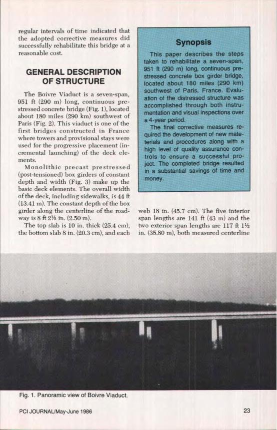
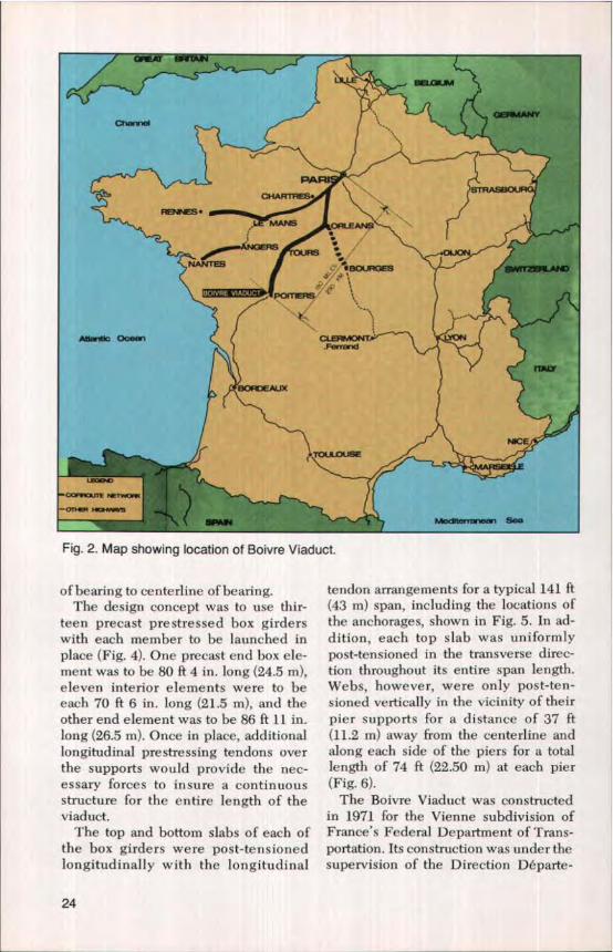
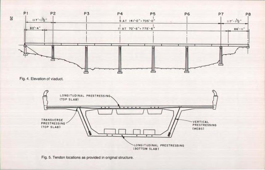
The Boivre Viaduct is a seven-span,951 ft (290 m) long, continuous pre-stressed concrete bridge (Fig. 1), locatedabout 180 miles (290 km) southwest ofParis (Fig. 2). This viaduct is one of thefirst bridges constructed in Francewhere towers and provisional stays wereused for the progressive placement (in-cremental launching) of the deck ele-ments.
Monolithic precast prestressed(post-tensioned) box girders of constantdepth and width (Fig. 3) make up thebasic deck elements. The overall widthof the deck, including sidewalks, is 44 ft(13.41 m). The constant depth of the boxgirder along the centerline of the road-way is 8 ft 2V in. (2.50 m).
The top slab is 10 in. thick (25.4 cm),the bottom slab 8 in. (20.3 cm), and each
SynopsisThis paper describes the steps
taken to rehabilitate a seven-span,951 ft (290 m) long, continuous pre-stressed concrete box girder bridge,located about 180 miles (290 km)southwest of Paris, France. Evalu-ation of the distressed structure wasaccomplished through both instru-mentation and visual inspections overa 4-year period.
The final corrective measures re-quired the development of new mate-terials and procedures along with ahigh level of quality assurance con-trols to ensure a successful pro-ject. The completed bridge resultedin a substantial savings of time andmoney.
web 18 in. (45.7 cm). The five interiorspan lengths are 141 ft (43 m) and thetwo exterior span lengths are 117 ft 11in. (35.80 m), both measured centerline
Fig. 1. Panoramic view of Boivre Viaduct.
PCI JOURNALJMay-June 1986 23
cry aa 9WAAW
PARTcHAPm S.
Fs. NMANS
1 rRS
NANTES BOURQES /CFO
Atlwi c OCR I:LEFEY10Nfr ,•
raur6OFK)ElW X
NICE
e
Gac^n rr+x„x
-Or H Nflr 8AO
gpAN Edten ,e , SO
Fig. 2. Map showing location of Boivre Viaduct.
of hearing to centerline of bearing.The design concept was to use thir-
teen precast prestressed box girderswith each member to be launched inplace (Fig. 4). One precast end box ele-ment was to be 80 ft 4 in. long (24.5 m),eleven interior elements were to beeach 70 ft 6 in. long (21.5 m), and theother end element was to be 86 ft 11 in.long (26.5 m). Once in place, additionallongitudinal prestressing tendons overthe supports would provide the nec-essary forces to insure a continuousstructure for the entire length of theviaduct.
The top and bottom slabs of each ofthe box girders were post-tensionedlongitudinally with the longitudinal
tendon arrangements for a typical 141 ft(43 m) span, including the locations ofthe anchorages, shown in Fig. 5. In ad-dition, each top slab was uniformlypost-tensioned in the transverse direc-tion throughout its entire span length.Webs, however, were only post-ten-sioned vertically in the vicinity of theirpier supports for a distance of 37 ft(11.2 m) away from the centerline andalong each side of the piers for a totallength of 74 ft (22.50 m) at each pier(Fig. 6).
The Boivre Viaduct was constructedin 1971 for the Vienne subdivision ofFrance's Federal Department of Trans-portation. Its construction was under thesupervision of the Direction Departe-
24
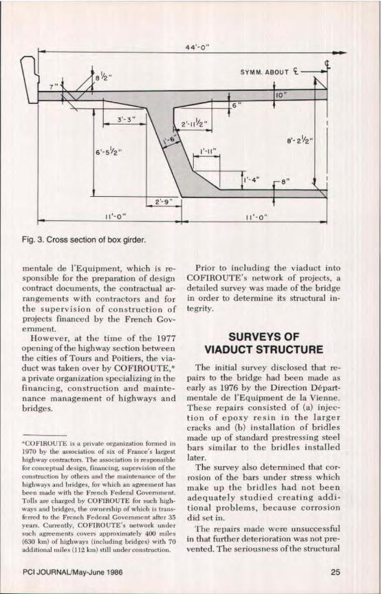
Fig. 3. Cross section of box girder.
mentale de l'Equipment, which is re-sponsible for the preparation of designcontract documents, the contractual ar-rangements with contractors and forthe supervision of construction ofprojects financed by the French Gov-ernment.
However, at the time of the 1977opening of the highway section betweenthe cities of Tours and Poitiers, the via-duct was taken over by COFIROUTE,*a private organization specializing in thefinancing, construction and mainte-nance management of highways andbridges.
*COFIROU1 E is a private organization formed in1970 by the association of six of France's largesthighway contractors. The association is responsibletot conceptual design, financing, supervision of theconstruction by others and the maintenance of thehighways arid bridges, for which an agreement hasbeen made with the French Federal Govemnient.Tolls are charged by COFIROUTE for such high-ways and bridges, the ownership of which is trans-ferred to the French Federal Government after 35years. Currently, COFIROUTE's network undersuch agreements covers approximately 400 miles(630 km) of highways (including bridges) with 70additional miles (112 kin) still umtereonstruction.
Prior to including the viaduct intoCOFIROUTE's network of projects, adetailed survey was made of the bridgein order to determine its structural in-tegrity.
SURVEYS OFVIADUCT STRUCTURE
The initial survey disclosed that re-pairs to the bridge had been made asearly as 1976 by the Direction Depart-mentale de l'Equipment de ]a Vienne.These repairs consisted of (a) injec-tion of epoxy resin in the largercracks and (b) installation of bridlesmade up of standard prestressing steelbars similar to the bridles installedlater.
The survey also determined that cor-rosion of the bars under stress whichmake up the bridles had not beenadequately studied creating addi-tional problems, because corrosiondid set in.
The repairs made were unsuccessfulin that further deterioration was not pre-vented. The seriousness of the structural
PCI JOURNAUMay-June 1986 25
Pf P2 P3 P4 P5 P6 P7 P8rn
Fig. 4. Elevation of viaduct.
LONGITUDINAL PRESTRESSING(TOP SLAB)
TRANSVERSEPRESTRESSING(TOP SLAB)
VERTICALPRESTRESSING(WEBS)
LONGITUDINAL PRESTRESSING(BOTTOM SLAB)
Fig. 5. Tendon locations as provided in original structure.

L0Czr
CCRf
C) ROSS BEANS
fi-- 43.00 m
m n
Fig. 6. Longitudinal section showing longitudinal tendons and anchorages for typical 141 ft (43 m) span.
CL PIER 1-- (L PIER
I/ ^^ ` LONGITUDINAL CRACK a roP SLA `^L
"-JUNCTIONOF WEB a TOP SLAB EB ICRACKSWEB CRACKS . b TYP.LONGITUDINAL CRACK 4 AT
L /JUNCTION OF WEB 8 BOTTOM SLAB
t (CRACKS " c " IN BOTTOM SLAB I N CROSS BEAMIN VICINITY OF PIER SUPPORT
141 0" I 141-0 141-0
4 Fig. 7. Longitudinal section through box girder showing the types of cracks together with their location and direction [typical 141 ft (43 m) span].
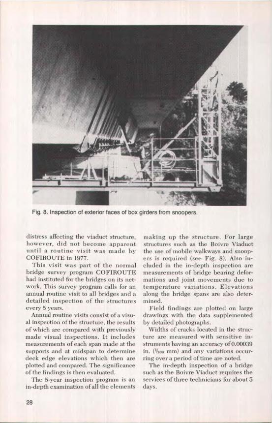
Fig. 8. Inspection of exterior faces of box girders from snoopers.
distress affecting the viaduct structure,however, did not become apparentuntil a routine visit was made byCOFIROUTE in 1977.
This visit was part of the normalbridge survey program COFIROUTEhad instituted for the bridges on its net-work. This survey program calls for anannual routine visit to all bridges and adetailed inspection of the structuresevery 5 years.
Annual routine visits consist of a visu-al inspection of the structure, the resultsof which are compared with previouslymade visual inspections. It includesmeasurements of each span made at thesupports and at midspan to determinedeck edge elevations which then areplotted and compared. The significanceof the findings is then evaluated.
The 5-year inspection program is anin-depth examination of all the elements
making up the structure. For largestructures such as the Boivre Viaductthe use of mobile walkways and snoop-ers is required (see Fig. 8). Also in-cluded in the in-depth inspection aremeasurements of bridge bearing defor-mations and joint movements due totemperature variations. Elevationsalong the bridge spans are also deter-rmrined.
Field findings are plotted on largedrawings with the data supplementedby detailed photographs.
Widths of cracks located in the struc-ture are measured with sensitive in-struments having an accuracy of 0.00039in. (Moo mm) and any variations occur-ring over a period of time are noted.
The in-depth inspection of a bridgesuch as the Boivre Viaduct requires theservices of three technicians for about 5days.
28
.D
0CMz
C
ANCHORAGE OF UPPER TENDONS
CCDED
LP
CRACKS
ANCHORAGE OF LOWER TENDONSEXTENSOMETRICGAUGES
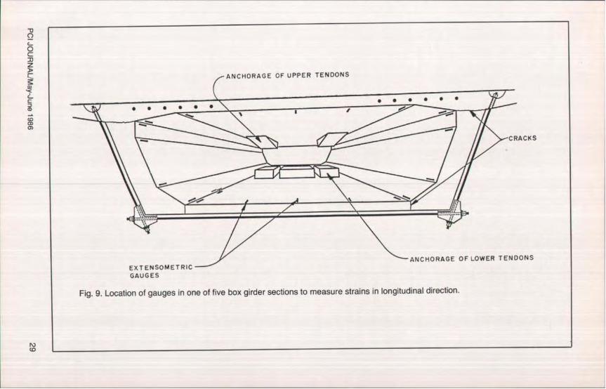
Fig. 9. Location of gauges in one of five box girder sections to measure strains in longitudinal direction.
N)CD

Fig. 10. Location of gauges in box girder to measure strains in transverse direction.
Findings of AnnualRoutine Survey
The cracking patterns uncoveredduring the routine inspection of thestructure are diagramatically shown inFig. 7 and can be categorized as follows:
Longitudinal Cracks — These crackscross the concrete width at the junctureof the webs and the bottom slab, as wellas at the juncture of the webs and topslab, almost completely separating theslabs from the webs (Cracks "a").
Inclined Web Cracks — In the webs,inclined cracks were found between thebottom and the top longitudinal ten-dons in the vicinity of the anchorages(Cracks "b").
Transverse Cracks — Transversecracks in the bottom slab were foundbehind the anchorages of the longitudi-nal tendons (Cracks "c").
Vertical Cracks — Localized, midspanvertical cracks occurred in the webs ofthe interior spans, beginning at the bot-tom of the webs for variable heights [30in. (76.2 cm) maximum height), andcould only be detected when thermalresponse parameters such as solar radi-ation, ambient temperatures, or windspeed fluctuations were acting on thestructure.
The seriousness of discovering such alarge number of cracks, some reaching
widths up to 1/a in. (6.35 mm), left theengineers no choice but to develop anadditional, comprehensive survey pro-gram for this specific viaduct. The pur-pose of this new survey was to obtain abetter understanding of the behavior ofthe structure so that adequate correctivemeasures could be developed andapplied.
Additional ComprehensiveSurvey Program forBoivre Viaduct
The additional survey program in-eluded the foIIowing tasks:
1. Detailed Monthly Site Inspections— These inspections included examin-ing the box girders carefully each monthand measuring the cracks found. By pro-gressively plotting the cracks, it waspossible to determine crack width vari-ations with elapsed time.
2. Detailed Inspection of ExteriorFaces of Box Girders — Detailed in-spections of the exterior faces of the boxgirders were made at 6-month intervalsfrom moving scaffolds and snoopers (seeFig. 8).
3. Topographic and Planimetric Con-trol System — A topographic andplanimetric control system using 162points inside the structure and distrib-
30
uted over 27 transverse sections (or sixpoints per section) was developed.
4. Extensometric Gauges — As shownin Figs. 9 and 10, a large number of ex-tensometric gauges were installed in thebox girders to measure strains in boththe longitudinal and transverse direc-tions. Altogether, a total of 110 longitu-dinal extensometric gauges were in-stalled in five transverse sections, i.e.,22 gauges per section, as shown in Fig. 9in order to measure strains in thelongitudinal direction. In addition, 77gauges were installed to measure thetransverse strains in seven sections(see Fig. 10).
5. Loading Tests — To determine theactual behavior of the structure underlive load, full scale loading tests wereconducted. These tests involved placingtrucks on the bridge decks.
Laser flexigraphs and inclinometerspositioned at the pier tops measured theresulting deformations. By means ofstrain gauges, the stress distribution be-tween webs and slabs was determinedfairly accurately.
Inspection and Loading Testsof Additional Survey Program
Both monthl y and 6-monthly bridgeinspections described above were madeduring a 4-year period in order to studyand evaluate the long-time behavior ofthe structure (see Fig. 11).
The major observations and findingswere as follows:
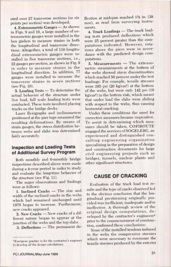
1. Inclined Cracks — The size andwidth of the inclined cracks in the webs.which had remained unchanged until1979 began to increase. Furthermore,new cracks appeared.
2. New Cracks — New cracks of a dif-ferent nature began to appear at thejunction of the webs and the top slabs.
3, Deflections — The permanent de-
*European practice is for the contractor's engineerto develop all the design calculations.
flection at midspan reached 1 y in. (38mm), as read from surveying instru-ments.
4. Truck Loadings — The truck load-ing tests produced deflections whichwere 25 percent greater than the com-putations indicated. However, rota-tions above the piers were in accor-dance with the predicted design com-putations.
5. Measurements — The extenso-metric measurements at the bottom ofthe webs showed stress discontinuitieswhich reached 50 percent under the testloadings: For example, tensile stresseswere 285 psi (20 kg'cm2) at the bottomof the webs, but were only 142 psi (10kg/cm) in the bottom slab, which meantthat under load the slabs were slidingwith respect to the webs, thus causinghorizontal cracking.
Under these conditions the need forcorrective measures became imperative.To assist in determining which mea-sures should be taken, COFIROUTEengaged the services of SOGELERG, anexperienced and distinguished con-sulting engineering organizationspecializing in the preparation of designand construction documents for largecivil engineering projects such asbridges, tunnels, nuclear plants andother significant structures,
CAUSE OF CRACKINGEvaluation of the truck load test re-
sults and the type of cracks observed Iedto the obvious conclusion that the lon-gitudinal prestressing originally pro-vided was inefficient, inadequate and/orineffective. A thorough review of theoriginal design computations, de-veloped by the contractor's engineers*prior to the commencement of construc-tion, confirmed these conclusions:
None of the installed tendons inducedin the webs the compressive stresseswhich were necessary to overcome thetensile stresses produced by the exterior
PI JOURNAL/May-June 1986 31
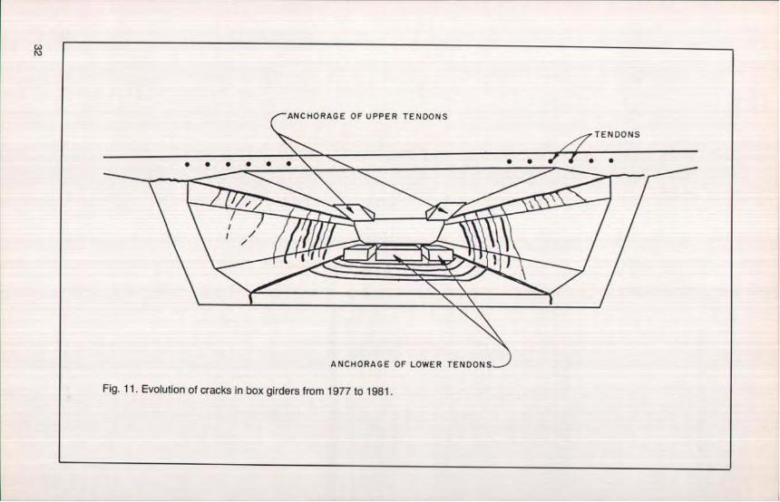
Fig. 11. Evolution of cracks in box girders from 1977 to 1981.
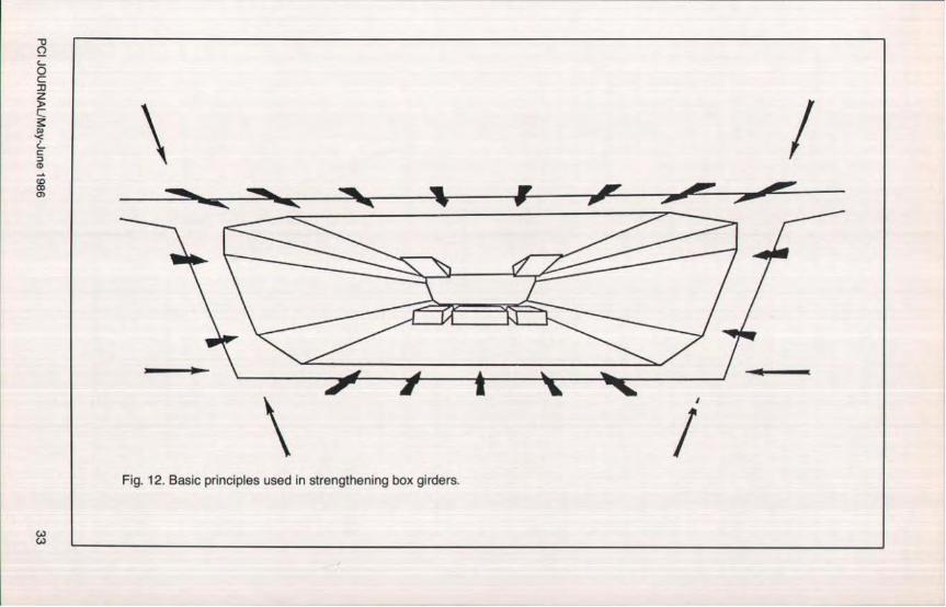
Fig. 12. Basic principles used in strengthening box girders.
0C30z
C-
=
Ioads. This was because all of the 142 ft(43 m) long tendons were straight andhad been placed in the slabs. Regret-tably, no longitudinal draped tendonsof any kind had been called for in thedesign/analysis. Therefore, the trans-verse and inclined tendons which wereinstalled in the structure did not providethe required compressive stresses in thewebs.
In addition, the longitudinal tendonswere anchored in clusters, producinghigh localized stress concentrations.The total forces produced were 3500kips (1760 short tons). The design asoriginally developed, combined withthe lack of adequate mild reinforcingsteel, made the necessary stress distri-bution an impossibility.
It also became evident that the crackshad dramatically changed the behaviorof the original monolithic structure andthat a new design/anal ysts had to bedeveloped for what was now a "cracked"
concrete structure.Before taking into account the crack-
ing of the concrete, computationsshowed that the tensile stresses at thebottom of the webs under normal loadsand conditions reached 990 psi (70 kg/cm 2 ). The shearing forces producedstresses of 700 psi (50 kg/em2 ). The de-termination of the stresses of a structuredesigned to be monolithic, but which isaltered by the presence of numerouscracks, is a very complex problem.
To overcome the difficulties, a com-puting procedure was established inwhich a finite element program forstress distribution in the vicinity of theanchorages was used. Taking into ac-count the severe cracking of the struc-ture, new calculations showed that thestressing operations of the tendonsshould have produced differentialmovements between the webs and thebottom slab of approximately to ¼ in.(3.2 to 6.4 mm).
HALF CROSS-SECTION
BRIDLE COURSEWATER PROOFING MEMIRANE
UPPER SLAB
LOWER SLAB
10•
WEB
19
1,9
STAINLESS STEELBARS IP 37MM L=IO'-4°
ESIN MORTAR
8" 1h14 STEEL SHOE
STAINLESS STEELBARS 0 37MM L244"
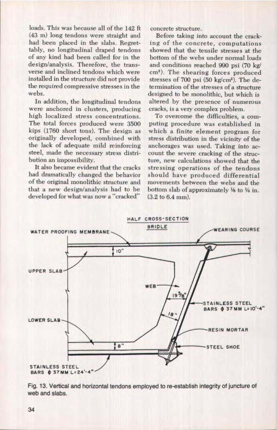
Fig. 13. Vertical and horizontal tendons employed to re-establish integrity of juncture ofweb and slabs.
34

ANCHORAGE END BLOCKXISTING TENDONS
,-lo NEW ANCHOR PLATELONGITUDINAL TENDONS
ANCHORAGECHAMBER
EXISTING ` ELASTOMERIC
TENDONS/ BEARING PAD'.-FRICTION
FREE BEARING
CENTER LINEEND SUPPORT
Fig. 14. Longitudinal section at end anchorage block showing new longitudinal tendons_
REQUIREMENTS FORADDITIONAL TENDONS
To rehabilitate and strengthen thestructure, it was necessary to install newtendons in such a manner that the re-sulting concrete stresses, produced bythe combination of the rehabilitatedexisting tendons and the new tendons,would remain within the allowablelimits in each and every section of thebox girder throughout the entire lengthof the viaduct (see Fig. 12).
To achieve this goal, it was necessaryto first re-establish the strength andstructural integrity of the junctures ofwebs and slabs and then to add, over theentire cross section of the box girder forthe entire length of the viaduct, com-pression forces which would producecompressive stresses of about 570 psi(40 kg/cm2).
Installing appropriately located verti-cal, transverse and longitudinal tendonswould produce, when stressed, the nec-essary forces for the required compres-sive stresses. To re-establish the effec-tiveness of the juncture of the slabs and
webs, and at the same time increase theshearing strength of the webs, newtransverse and vertical tendons (see Fig.13) near the pier supports for a distanceof about 42 ft (13 m) would produce therequired vertical compressive stresses.
Lastly, the installation of appropri-ately located longitudinal tendons (seeFig. 14) from one end of the viaduct tothe other would produce the additionalhorizontal compressive stresses desired.The new tendons, when combined withthe restored, existing longitudinal ten-dons in the slabs (the only existingflexural reinforcement so far) wouldmake the structure capable of carryingthe superimposed design loads whichthe originally constructed viaduct couldnot.
Based on the assumption that theabove forces could indeed be furnishedin the field and that the required resto-ration could be carried out, the actualstructural strength of the rehabilitatedstructure was recomputed by the finiteelement program mentioned previously.
These computations indicated that thecombined compressive stresses thus
PCI JOURNALMay-June 1986 35

produced would be about 3100 psi (220kg/cm) in the high stress concentrationareas near the pier supports.
To determine whether the existingconcrete in the bridge could safely sus-tain such high compressive stresses,sonic tests at 4500 points throughout thestructure were made. Note that the ac-tual concrete strengths varied from 6260to 10,700 psi (440 to 750 kglcmt).
The probability of finding concretecompressive strengths of less than 6400psi (450 kg/cm2) in areas of high stressconcentrations was considered minimal(less than 1 percent).
RequiredTransverse and VerticalPrestressing Forces
The required transverse and verticalprestressing of the box girders was to beaccomplished by means of externaltransverse tendons along the bottomslab and inclined vertical tendons alongthe webs as shown in Fig. 13. Thisformed a type of envelope defined here-in as a "bridle."
At the top slab the inclined tendonswere to be anchored in a pocket underthe wearing course (Fig. 13) while at thebottom a steel shoe arrangement, an-chored to the concrete by means of aresin mortar, was to be furnished. Thedesign/analysis indicated that a total of156 bridles would be required for theentire structure. Each bridle was de-signed to produce a force of 176 kips (85short tons),
1. Makeup of Transverse and VerticalTendons — To produce the necessary176 kip (85 short tons) force, six 1.45 in.(36.8 mm) diameter bars were requiredfor each of the 156 bridle tendons in-stalled over the entire viaduct. Thetwo bottom transverse bars were 24 ft 4in. (7.41 m) long and the four shorter in-clined bars were 10 ft 4 in. (3.15 m) long(see Fig. 15).
2. Criteria for Maintaining Stresses by
Means of External Tendons — The fol-lowing three basic criteria had to besatisfied:
(a) Prevention of Corrosion. Protec-tion against corrosion must be highlyefficient and long lasting because, inrestoration work particularly, access tomany tendon areas, especially at the an-chorages, may be difficult. Thus, a reli-able means of corrosion protection hadto be developed.
(b) Minimizing of Undesirable Strains.Since stress can only be inducedin tendons by strains which are a func-tion of tendon length, any variation instrain in short tendons, due to seating ofthe anchorage for example, can seriouslyaffect the magnitude of the stress re-quired to be maintained. Note that per-centage wise, for the same amount ofstrain, the stress losses will be muchgreater in short tendons than in longtendons. Thus, quality assurance controlbecomes a very important factor.
(c)Maintenance of Stress Induced. Toascertain that the stresses induced in thetendons proper and in their anchoragesare maintained, devices for checkingstresses at regular intervals had to bedeveloped.
3. Corrosion Protection — Selection ofType of Steel for Tendons — Since cor-rosion had set in the bars of the bridlesinstalled prior to COFIROUTE's sur-veys, it was considered imperative thatthe new exposed bars had to be pro-tected from corrosion, if indeed barswere to be used as tendons. It was nec-essary to develop bars made of a steelwhich would be inherently resistant tocorrosion while at the same time havethe appropriate mechanical propertieswhich are required in prestressing work.Corrosion resistance of such a steel fun-damentally results from the formationon its surface of a thin film of inertoxides, which is capable of spontaneousreconstruction in case of damage.
Meeting these criteria was an absolutenecessity in the case of the Boivre Via-duct because its lifetime expectancy de-
36
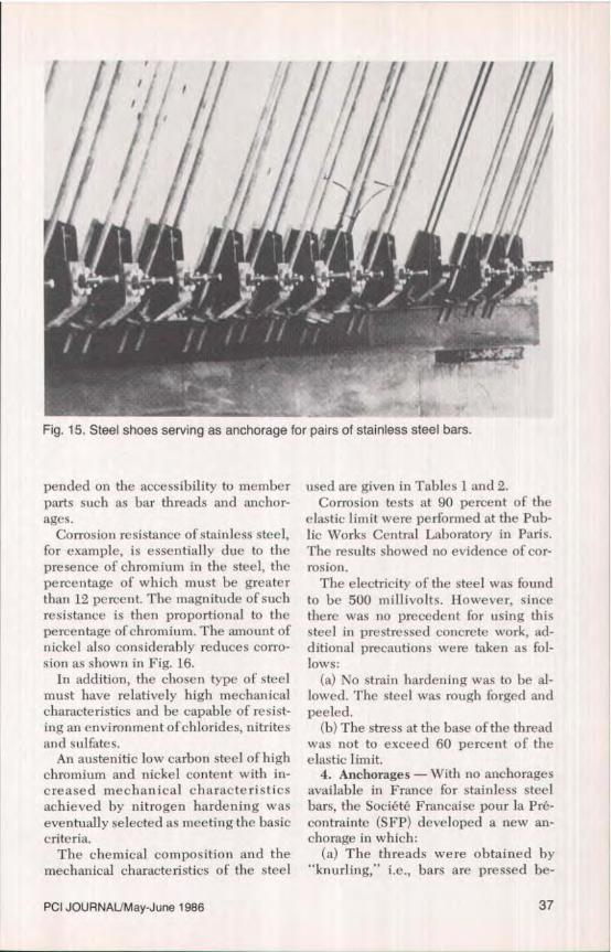
Fig. 15. Steel shoes serving as anchorage for pairs of stainless steel bars.
pended on the accessibility to memberparts such as bar threads and anchor-ages.
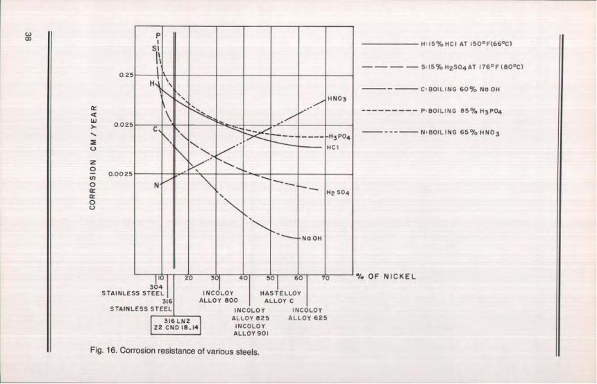
Corrosion resistance of stainless steel,for example, is essentially due to thepresence of chromium in the steel, thepercentage of which must be greaterthan 12 percent. The magnitude of suchresistance is then proportional to thepercentage of chromium. The amount ofnickel also considerably reduces corro-sion as shown in Fig. 16.
In addition, the chosen type of steelmust have relatively high mechanicalcharacteristics and he capable of resist-ing an environment of chlorides, nitritesand sulfates.
An austenitic low carbon steel of highchromium and nickel content with in-creased mechanical characteristicsachieved by nitrogen hardening waseventually selected as meeting the basiccriteria.
The chemical composition and themechanical characteristics of the steel
used are given in Tables 1 and 2.Corrosion tests at 90 percent of the
elastic limit were performed at the Pub-lic Works Central Laboratory in Paris.The results showed no evidence of cor-rosion.
The electricity of the steel was foundto be 500 millivolts. However, sincethere was no precedent for using thissteel in prestressed concrete work, ad-ditional precautions were taken as fol-lows:
(a) No strain hardening was to be al-lowed. The steel was rough forged andpeeled.
(b) The stress at the base of the threadwas not to exceed 60 percent of theelastic Iimit.
4. Anchorages — With no anchoragesavailable in France for stainless steelbars, the Societe Francaise pour la Pro-contrainte (SFP) developed a new an-chorage in which:
(a) The threads were obtained by"knurling," i.e., bars are pressed be-
PCI JOURNALJMay-June 1986 37
WMI PI
S^
H ^
HNO3
H3PO4
HC1
N ^H2 S0 4
NO 0H
I- CV JV) YV Zfl)I OV lV
304
STAINLESS STEEL INCOLOY HASTELLOY316 ALLOY 800 ALLOY C
STAINLESS STEEL INCOLOY INCOLOY316 LN2 I ALLOY 825 ALLOY 625
172 CNDI8..141 INCOLOYALLOY 901
0.2°
tz
0.02°
z0- 0.0025
0G:
0U
1415% HGAT 150°F(66°C)
-i - - S:15%H2SO4AT 176°F{80°C)
- C:BOILING 60% NOOH
--------- P : BOILING 85% H3PO4
--- N:BOfLING 65% HNO3
% OF NICKEL
Fig. 16. Corrosion resistance of various steels.

tween rollers which indent the threads.(b) Stainless steel and carbon steel
remained separate.(c) Nut and washer interfaces are
spherical, to minimize undesirablebending stresses. Thus, the anchorageconsists of a bar threaded at its ends, anut with a spherical base, a circularwasher with a spherical upper face, aninsulated washer, and a nylon washer(see Fig. 17a). A detail of the threads isshown in Fig. 17h.
5. Quality Assurance Control for Fab-rication of Bars — Four castings pro-duced about 38.5 short tons of stainlesssteel bars of the quality required. Fourcomplete corrosion tests, a tensile teston 1.45 in. (37 mm) diameter bar, threeseries of tensile controls on test speci-mens and a complete chemical analysiswere made for each casting. Each of thenuts, bars and washers were individu-ally checked.
All bars with their accessories weredelivered to the construction site incrates to which control certificates wereattached.
6. Laboratory Quality AssuranceControl of Bars — The laboratory testswere made iii the Central Public WorksLaboratory. Recording strain gauges,giving directly the stress-strain curves,were attached to each bar together witha mechanical extension gauge andGloetzl cell, which is a calibrated hy-draulic flat jack.
During the tests the required stress-strain procedures were defined and thesteel's mechanical characteristics wereverified.
7. Installation and Stressing of Trans-verse and Inclined Tendons
(a) Maintenance of Traffic. Since theBoivre Viaduct could not be closed tovehicular traffic, the installation andstressing of the transverse and inclinedtendons was difficult and thereforeschemes for maintaining traffic had to bedevised.
The requirement of maintaining threelanes of traffic open at all times could
Table 1. Chemical composition of stainlesssteel bars used in this project.
ElementPer-cent Element
Per-cent
Chromium 18.0 Silica 1.0Nickel 14.0 Sulfur 0.036Molybdenum 3.0 Phosphorus 0.030Manganese 2.0 Nitrogen 0.20Carbon 0.05 Iron 62.0
Table 2. Mechanical characteristics ofstainless steel bars used in this project.
Ultimate stress: 142,200 psi (100 kg/cm2)Elastic limit: 120,900 psi (85 kg/cm2)Minimum elongation (necking free): 6
percentMinimum elongation at rupture: 24
percentResilience at low temperature: 120 jlcm2Stress relaxation at 90 percent of elastic
limit; 2.4 percentModulus of elasticity: 25,600,000 psi
(18000 kg/cm2)
Note: The above mechanical characteristicscould be considerably increased by strain
hanle ring.
only he met after the completion of asecond bridge adjacent to the BoivreViaduct. Therefore, any rehabilitation ofthe viaduct could not commence until1976.
Two of the three lanes required tomaintain traffic became available on theadjacent new structure.
The third lane (on the original via-duct) was made available through theadoption of a three-stage rehabilitationprocedure:
During the first stage, the center laneremained open to traffic. This permittedall construction related to the installa-tion and stressing of the transverse andinclined tendons to be carried out.
During the second and third stages,traffic was permitted on either one of theoutside lanes, thus allowing construe-
PCI JQURNALlMay-June 1986 39

tion of the required new anchor blocksfor the new longitudinal tendons.
(b) Construction of Bridles. Sinceconstruction of the bridles requiredsimultaneous access to both the top andbottom of the structure, two walkwayswere required.
The most difficult operation was the
niI 1.d .,... Ukill 1 1 i5 16 '.f 1
Fig. 17a. Bar anchorage developed inFrance for stainless steel of the type usedin the rehabilitation of the viaduct.
boring of the holes through the top slabssince contact between the concrete andthe tendons had to be avoided. This re-quired a high degree of precision. Theboreholes were drilled with diamondcore drills.
(c) Stressing of Tendons. Six hydrau-lic jacks fed by six synchronized pumpswere used to stress the tendons. Stress-ing was to he executed in two steps sep-arated by an interval of time to allowtotal relaxation, i.e., to allow compensa-tion for initial creep losses. It was in-deed determined that the initial tensilelosses would not exceed 3 percent of theinitial stresses induced in the bars.
(d) Field Quality Assurance Control(1) Boreholes
An independent surveyorchecked the accuracy of thesize and location of the bore-holes.
(2) Stressing of TendonsA detailed quality assurancecontrol program for thestressing of the tendons wasdeveloped. It included thefollowing elements:
a. Mechanical strain gauges wereused to check the accuracy of thestressing procedures on 5 per-cent of the total number of ten-
Fig. 17b. Threads at end of bars.
40

dons, which represented 10 per-cent of the entire bridle tendons.
b. In each span one bridle tendonwas chosen at random to besubjected to the followingchecks:— Elongations by means of me-
chanical strain gauges placedon the bars making up thetendon.
— Four displacement gauges tobe set on the cracks.
— A series of 11 strain gauges tobe placed on the concrete. Inaddition, on one bridle ineach span, a series of Gloetzlcells were installed,
To further insure accuracy in thestressing operation, the elongations ofthe bars were isolated from all otherpossible related movements, such assettlement of the top slab and compres-sion of the anchorage components.
Finally, in order to observe thelong-term behavior of the gauges andGloetzl cells, these devices were in-stalled to remain in place permanently.
In general, it was found that the con-trol values attained in the field agreedfairly well with the predicted valuesobtained from the design calculations.
Longitudinal Prestressing
1. Composition and Number ofTendons — To withstand the normalload conditions, a compressive stress ofapproximately 600 psi (42 kglcm2 ) had tobe produced through additional longi-tudinal prestressing.
This stress corresponds in this case toa force of 6600 kips (3300 short tons)over the entire cross section of the boxgirders. Ten tendons, each +965 ft(±294 m) long and each made up ofseventeen % in. (15.7 mm) diameter gal-vanized strands totaling 3.95 stl in. (2550mm2 ), were required to produce thisprestressing force.
2. End Anchor Blocks — Computa-tions determined that the existing end
cross beams could not carry the 6600 kip(3300 short tons) force. Therefore, newreinforced concrete end anchorageblocks had to he designed and con-stnicted so that the forces could result ina uniform stress distribution. The exist-ing anchorages of the longitudinal ten-dons made the need for uniforml y dis-tributed stresses of the new tendons im-perative to avoid major problems.
The presence of the bridles dictatedthe location of the longitudinal tendonsand left the designer with no choice butto locate these inside of the box girders.To obtain the desired uniform compres-sive stress distribution in each sectionthroughout the entire length of thestructure, the resultant of the prestress-ing forces produced by these additionaltendons had to be located as closely aspossible to the center of gravity (neutralaxis) of the cross section of the boxgirders.
The problem is a relatively simpleone in the case of a noncracked beambut more complex for a cracked beam.To obtain a uniform stress distribution,the anchorage blocks were designedwith stiffeners.
The design called for the constructionof 3 ft 3 in. (1 m) thick reinforced con-crete end blocks to he stiffened by three6 ft 6 in. (2 m) thick beams and rein-forced with 500 lb of mild reinforcingsteel per cubic yard (about 300 kg/m3).
For details refer back to Fig. 14. The tenanchorages bear on two 4 ft x 3 ft 3 in.(120 x 1 m) steel plates (see Fig. 18).
3. Installation of Longitudinal Ten-dons and 'Their Protection FromCorrosion — Metal duct supports wereused to hold in place the 41/'2 in. (114mm) diameter reinforced glass fiberduct which enclosed the galvanizedsteel strands. The supports were boltedto reinforced concrete blocks spaced on13 ft (4 m) centers in order to preventpossible vibrating resonance problemsbetween the tendons and the structure(see Fig, 19).
Although the strands were galvanized
PCI JOURNAUMay-June 1966 41

Iv
END ANCHORAGE BLOCKBEARING ANCHORAGE PLATE
v ^ F^y^ ^ t • ^^` ^ 1r
r r
ANCHORAGE CHAMBER
Fig. 18. End view of end anchorage block showing location of tendon bearing plates.
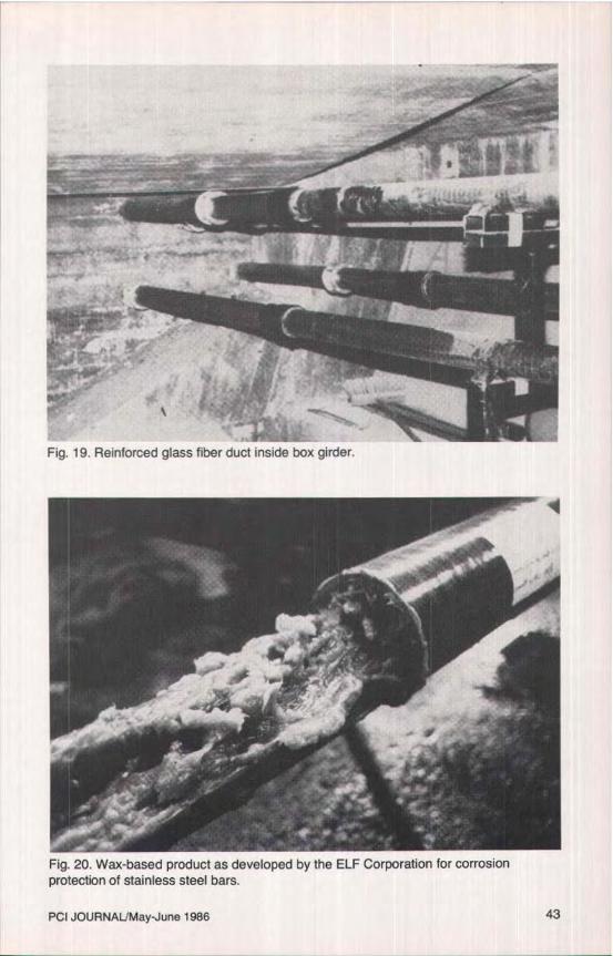
Fig. 19. Reinforced glass fiber duct inside box girder.
Fig. 20. Wax-based product as developed by the ELF Corporation for corrosionprotection of stainless steel bars.
PCI JOURNAL/May-June 1986 43
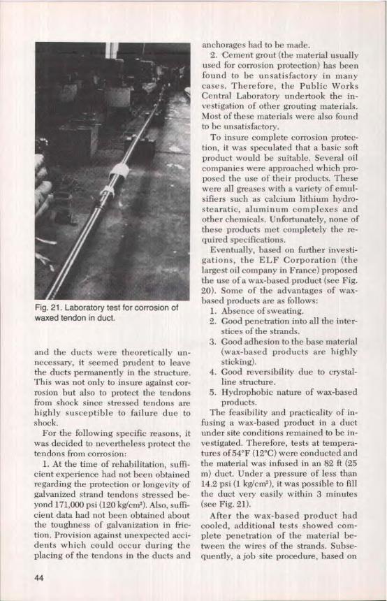
Fig. 21, Laboratory test for corrosion ofwaxed tendon in duct.
and the ducts were theoretically un-necessary, it seemed prudent to Ieavethe ducts permanently in the structure.This was not only to insure against cor-rosion but also to protect the tendonsfrom shock since stressed tendons arehighly susceptible to failure due toshock.
For the following specific reasons, itwas decided to nevertheless protect thetendons from corrosion:
1. At the time of rehabilitation, suffi-cient experience had not been obtainedregarding the protection or longevity ofgalvanized strand tendons stressed be-yond 171,000 psi (120 kglcm 2 ). Also, suffi-cient data had not been obtained aboutthe toughness of galvanization in fric-tion. Provision against unexpected acci-dents which could occur during theplacing of the tendons in the ducts and
anchorages had to be made,2. Cement grout (the material usually
used for corrosion protection) has beenfound to be unsatisfactory in manycases. Therefore, the Public WorksCentral Laboratory undertook the in-vestigation of other grouting materials.Most of these materials were also foundto be unsatisfactory.
To insure complete corrosion protec-tion, it was speculated that a basic softproduct would be suitable, Several oilcompanies were approached which pro-posed the use of their products. Thesewere all greases with a variety of emul-sifiers such as calcium lithium hydro-stearatic, aluminum complexes andother chemicals. Unfortunately, none ofthese products met completely the re-quired specifications.
Eventually, based on further investi-gations, the ELF Corporation (thelargest oil company in France) proposedthe use of a wax-based product (see Fig.20). Some of the advantages of wax-based products are as follows:
1. Absence of sweating.2. Good penetration into all the inter-
stices of the strands.3. Good adhesion to the base material
(wax-based products are highlysticking).
4. Good reversibility due to crystal-line structure.
5. Hydrophobic nature of wax-basedproducts.
The feasibility and practicality of in-fusing a wax-based product in a ductunder site conditions remained to be in-vestigated. Therefore, tests at tempera-tures of 54°F (12°C) were conducted andthe material was infused in an 82 ft (25m) duct. Under a pressure of less than14.2 psi (1 kg/cm2 ), it was possible to fillthe duct very easily within 3 minutes(see Fig. 21).
After the wax-based product hadcooled, additional tests showed com-plete penetration of the material be-tween the wires of the strands. Subse-quently, a job site procedure, based on
44
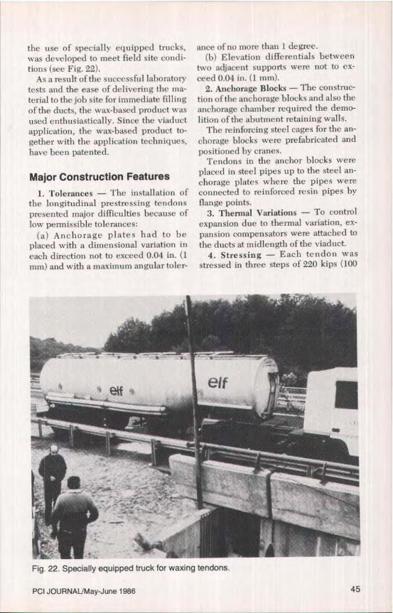
the use of specially equipped trucks,was developed to meet field site condi-tions (see Fig. 22).
As a result of the successful laboratorytests and the ease of delivering the ma-terial to the job site for immediate fillingof the ducts, the wax-based product wasused enthusiastically. Since the viaductapplication, the wax-based product to-gether with the application techniques,have been patented.
Major Construction Features1. Tolerances — The installation of
the longitudinal prestressing tendonspresented major difficulties because oflow permissible tolerances:
(a) Anchorage plates had to beplaced with a dimensional variation ineach direction not to exceed 0.04 in. (1mm) and with a maximum angular toler-
ance of no more than 1 degree.(b) Elevation differentials between
two adjacent supports were not to ex-ceed 0.04 in. (1 mm).
2. Anchorage Blocks — The construc-tion of the anchorage blocks and also theanchorage chamber required the demo-lition of the abutment retaining walls.
The reinforcing steel cages for the an-chorage blocks were prefabricated andpositioned by cranes.
Tendons in the anchor blocks wereplaced in steel pipes up to the steel an-chorage plates where the pipes wereconnected to reinforced resin pipes byflange points.
3. Thermal Variations — To controlexpansion due to thermal variation, ex-pansion compensators were attached tothe ducts at midlength of the viaduct.
4. Stressing — Each tendon wasstressed in three steps of 220 kips (100
Fig. 22. Specially equipped truck for waxing tendons.
PCI JOURNALIMay-June 1986 45
tons) each, at intervals of 1 month be-tween each step.
Three stages of 2200 kips (1000 tons)each for the ten tendons were required.Stressing demanded the use of two 500ton (454 t) capacity hydraulic jacks. Anelongation of 4 ft (12 m) was required toattain the total desired prestressingforce per tendon.
5. Protection Against Corrosion -Immediately after completion of thestressing operation, the wax-based ma-terial was introduced under Iow pres-sure at the lowest point of the tendons.Note that the previously mentionedspecially fitted trucks were used for thisoperation.
For each 965 ft (294 m) tendon, theanti-corrosion injection was completedin 40 minutes, including preparatorywork.
To protect the protruding 4 ft (1.2 m)length of tendon so that it could serve asa means of restressing should the needarise at some later date, steel coverswere used to seal the ends of the ten-dons.
Supervision of Construction
The supervision of construction in-cluded the following items of work:
1. Checking the characteristics of thematerial to insure that specificationswere met.
2. Recording by means of straingauges that the stressing of each pair oftendons was carried out accurately.
3. Measuring the size of main cracksafter each 2200 kip (1000 tons) stage.
4. Measurement of force transmissionratios were made on the first two ten-dons even though the tendons werestraight and the duct surfaces unusuallysmooth. The measured ratios rangedfrom 98 to 99 percent.
5. Checking jack pressures againstelongations during the entire stressingof the 965 ft (294 m) Iong tendons, withthe total elongation to be approximately4 ft (1.2 m).
It was determined that the field workwas carried out in accordance with thedesign computations.
EFFICIENCY OF THEREHABILITATION
To assess the efficiency of the rehabil-itation work performed on the BoivreViaduct, the structural and thermal be-havior of the bridge were evaluated to-gether with a review of the completiondates of the project.
Structural Behavior
To determine whether the rehabilita-tion measures described hereinachieved their purpose, all the elementsof the initial bridge inspected were re-viewed.
The easiest, simplest and most rapidway was to reload the structure with thetrucks as initially carried out and to re-cord the stresses produced in the reha-bilitated structure. This was done byconnecting all the previously installedextensometric and strain gauges placedon the cracks to a computer with twoscanners.
The truck loading gave excellent pos-itive results:
1. The deformations, which were 25percent larger than those indicated bythe computations made prior to the re-pair, were now 15 to 20 percent less.
2. Rotations remained slightly lessthan those computed.
3, The transmission of forces from onespan to the adjacent span became nor-mal again.
4. Stress diagrams in the box girdersection became linear again.
Thermal Behavior
Changes in stress due to temperaturevariations were recorded during a con-tinuous 24-hour period. From these ob-servations a temperature-stress rela-
46
tionship was calculated and a smallcomputer program was set up. Notethat thermal variations had to bedistinguished from the effects dueto loads.
Completion of RehabilitationWork
The Boivre Viaduct was never closedto traffic. Reconstruction began in Sep-tember 1982 and was completed in April1984 even though no construction waspermitted between April and Sep-tember 1983 in order to accommodatesummer travel.
CONTINUING OBSERVATIONOF VIADUCT'S BEHAVIORIn addition to the use of the checking
devices which were left in the structure,additional detailed inspections wereplanned at 6-month intervals.
During the first such inspection, madein September 1984, the tensile stressesin the bridle bars were checked. Nor-mally, such checking is made by meansof hydraulic jacks. However, becauseof the large number of bridles, a newtensile check method based on vi-bration frequency of the bars wasdeveloped.
Prior to attaching the vibratory gaugesto the bars in order to measure the ten-sile stresses in the bars, the gauges werecalibrated with high precision. Then thebars were made to vibrate by means of'asledge hammer.
Measurements of the cracks indicateda substantial reduction in their widths.Several cracks which were 0.04 in. (1mm) in size before the repairs measured
now 0.004 to 0.008 in. (0.1 to 0.2 mm),and no new cracks appeared.
Strain gauges between the webs andslabs indicated that no movements ofany kind such as sliding was takingplace.
After making due allowance for tem-perature differential between stainlesssteel and concrete, the actual stress vari-ations were found to be close to the val-ues anticipated by the design computa-tions.
CONCLUDING REMARKSThe normal behavior of the rehabili-
tated bridge at present, and as antici-pated, justified the total cost of the re-pair work which was of the order of 15million French Francs, i.e., about$1,800,000,* including all truck loadingtests and engineering studies. The costof a new viaduct, excluding demolitioncosts, would have been 27 millionFrench Francs or $3,300,000_
One side benefit of this project is thatthe rehabilitation effort stimulated thedevelopment of new techniques andmaterials for this type of constructionwhich resulted in reduced costs andgreater efficiency. For example, strainhardened stainless steel can now beused at higher stresses and provide re-sistance to corrosion.
The wax-based corrosion protectivematerial has been used effectively inthree other major bridges near the townof Nick, and after numerous additionaltests has performed to the satisfaction ofall parties concerned.
*Based on 8.2 French Francs per U.S. dollar.
NOTE: Discussion of this paper is invited. Please submityour comments to PCI Headquarters by January 1, 1987.
PCI JOURNALJMay-June 1986 47