a n a lternative g reen s creen k eying m ethod f or f ilm v isual e ffects
TRANSCRIPT

The International Journal of Multimedia & Its Applications (IJMA) Vol.7, No.2, April 2015
DOI : 10.5121/ijma.2015.7201 1
AN ALTERNATIVE GREEN SCREEN KEYING
METHOD FOR FILM VISUAL EFFECTS
Jin Zhi
Department of Creative Professions & Digital Arts,
University of Greenwich, United Kingdom
ABSTRACT
This study focuses on a green screen keying method developed especially for film visual effects. There are a
series of ways of using existing tools for creating mattes from green or blue screen plates. However, it is
still a time-consuming process, and the results vary especially when it comes to retaining tiny details, such
as hair and fur. This paper introduces an alternative concept and method for retaining edge details of
characters on a green screen plate, also, a number of connected mathematical equations are explored. At
the end of this study, a simplified process of applying this method in real productions is also tested.
KEYWORDS
Digital Compositing, Green Screen Keying, Visual Effects
1. INTRODUCTION
The green / blue screen keying technique has been used frequently in many fields for removing a
background from a subject, this technique also is called chroma keying in the visual effects
industry. The chroma keying technique was used for the first time in a feature film in 1933
[Richard 1994]. A further development of properly using the chroma keying process for creating
a traveling matte [1] was in the film, entitled ‘The Thief of Bagdad ’ in 1940 [2].
In the current digital era, because digital camera sensors are most sensitive to green color [Bryce
1976], the green screen is used more than other colors on set. However unlike digital sensors,
film cameras allow the light to pass through the other two layers of the R,G,B channels in order
to get the layer to record its particular color. Many visual effects film scenes choose green or blue
screens as a backdrop based on particular needs in the scenes.
In the visual effects industry, footage for film and TV commercials is usually shot at a higher
quantization, and scanned as well as delivered as a 10-bit DPX (log) [3] file format to visual
effects companies in order to fit the visual effects pipeline. As a part of the film chain, footage is
scanned from negative film to digital data and 10-bit logarithmic color space DPX (or Cineon)
files represent printing density, which is at the minimum quantization needed to retain the
original data information from negative film such as color component crosstalk and gamma value
[4].

The International Journal of Multimedia & Its Applications (IJMA) Vol.7, No.2, April 2015
2
There are many practical ways of keying mattes from green / blue screen plates. Instead of using
a single technique to create a single matte, it is often the case that a number of different mattes
are generated [Ron 2008]. In general, the most often used approach is to combine two types of
mattes: the garbage (core) matte and the soft matte.
A garbage matte is a quickly hand-drawn matte, which excludes parts of an image that a green /
blue screen would not remove. A soft matte is usually produced as a result of the green / blue
screen plates with fine details especially around edge of characters [5]. The result of adding these
two mattes together creates a high quality matte that will be ready for the next process. However,
the question is that soft mattes need to be created carefully in order to extract all the intricate
details, such as hair and thus the creation of soft mattes is a time-consuming process.
2. KEY FACTORS OF GREEN / BLUE SCREEN FOOTAGE
2.1. Chroma Subsampling
A typical way of encoding RGB color information is to use Y’CbCr color space. Y’ usually
denotes the luma component, Cb the blue-difference, and Cr indicates the red-difference chroma
component. Because of storage and transmission limitations, especially in the case of video
signals and digital photographs, and because the human visual system is more sensitive to
variations of luminance than color [6], a digital signal can be optimized by devoting wider
bandwidth to the luma component than to Cb and Cr color difference components. However,
some heavy compression schemes can cause degradation to green / blue screen keying. There is
no visual difference perceived, however, saturation compression in digital images results in
significant artifacts, which affect the final green / blue screen keying result.
There are several typical types of subsampling available for film and digital data encoding, such
as 4:4:4 Y’CbCr, 4:2:2, etc. High-end film scanners usually use 4:4:4 Y’CbCr, meaning all
components have the same sample rate. One SDI (serial digital interface) link carries a 4:2:2
signal, the other link carries a 0:2:2, and when these two links are combined they create a 4:4:4
signal. Some digital cameras do not have any chroma subsampling and record 4:4:4 R’G’B over
dual-link HD-SDI. Many other high-end digital cameras, such as Digital Betacam, DVCPRO50
/DVCPRO HD can encode two chroma components at half the sample rate of a luma component
with little to no visual difference [7].
Figure 1. A comparison of 4:4:4 and 4:2:2 encoded image

The International Journal of Multimedia & Its Applications (IJMA) Vol.7, No.2, April 2015
3
2.2. Linear and logarithmic color Space
Nowadays, most VFX studios choose linear color space [8] in their visual effects pipelines, one
of those major digital compositing applications – The Foundry Nuke is also designed to work in
linear color space, which is also called physical color space. In physical color space light laws
behave following linear laws. Additionally, mathematical formulas used for manipulating images
are designed to work well in physical color space.
Film scanned digital data in logarithmic color space is designed to carry as much color
information as possible, when a 10-bit log file is converted to a linear color space it stores data in
equal increments and each tonal step has equal weight. If the value range 0 to 1023 is remapped
to the project range, and conversion points are 95 and 685 on the 0-1023 scale, then pixel values
below 95 represent black values, and above 685 are considered. The logarithmic formula is
written as follows:
y = logb(x) (1)
y is the exponent and b is the base, a logarithm to base 10 (b=10) is called the common logarithm.
For instance, the log base 10 of 1000 is 3, or log10(1000) = 3, which equates to 103 = 1000. If a
visual effects project is set to 16-bit, once the 10-bit log file is converted to linear color space, the
value 95 becomes 0 and 685 becomes 32,768. Therefore the acceptable exposure range for the
log interpretation takes up roughly 58% of the project range. With the log interpretation, 33% is
lost to superwhite values and 9% is lost to superblack values. As a result, the log file appears
washed out on 8-bit computer monitors [9].
2. FORMAT AN ALTERNATIVE APPROACH OF KEYING GREEN SCREEN
According to the background knowledge introduced in the above sections, we intend to use green
screen plates as an example in the following experiments. However, the method used in the
experiment can also be applied to blue screen plates. The following image (Figure 2) shows how
a green screen plate looks with the 10-bit DPX file format in log color space on an 8-bit computer
display. As an industry-standard workflow in digital visual effects, all elements in different color
spaces will be converted into linear color space before any manipulation.
Figure 2. A 10-bit DPX file image in log color space

The International Journal of Multimedia & Its Applications (IJMA) Vol.7, No.2, April 2015
4
The following image shows the 10-bit DPX file image in linear color space after being converted
in a digital compositing application, and viewed on the same 8-bit computer monitor under sRGB
LUT.
Figure 3. The 10-bit DPX file image in linear color space
3.1. Process analyses of this approach of green screen keying
Unlike many other traditional ways of creating mattes from green / blue screens, a key concept of
this approach is first to extract green colors from the green screen plates, and then bake the plates
into background plates by using a number of mathematical equations, then, at the end, adding
another matte generated from the same green / blue screen plates on top of the one created
through the mathematical equations. By combining these two elements together, objects are
extracted from green / blue screen plates, and a reasonable amount of detail is retained on the
final composition. In order to simplify the complexity of these mathematical calculations for
artists, a gizmo node is created and introduced. Since the idea and mathematical equations are
clearly laid out, a simplified version of the mathematical calculations can be created and used in
other node-based as well as layer-based compositing applications, such as The Foundry’s Nuke,
Eyeon Fusion and Adobe After Effects.
Figure 4. The gizmo node
The gizmo node in Figure 4 shows the node with all the mathematical calculations inside and
three inputs for connecting different plates, such as fg (foreground), bg (background) and backing
color.
3.2. Analyses of mathematical equations inside the gizmo node
Digital compositing in VFX studios is processed in linear light space and prefers floating point in
order to keep high dynamic values. At the top part of the following image, there are three plates
(Read16, Read17 and Read18), which have been converted into linear color space through
previous operations. However, in order for the mathematical calculations to be carried out
correctly in this process, all plates in linear color space from this step must be converted back to
log color space first so the R,G,B values of the plates from the floating point values are decreased
to normal values.

The International Journal of Multimedia & Its Applications (IJMA) Vol.7, No.2, April 2015
5
Figure 5. All the steps inside the gizmo node
Figure 6. A comparison of two identical images in linear color space and log color space and being viewed
under linear LUT
The International Journal of Multimedia & Its Applications (IJMA) Vol.7, No.2, April 2015
6
Pixel values in the red square region of the upper image in Figure 6 show in R,G,B channels as
follows:
0.79644, 7.65045, 12.37791 (2)
In contrast, the lower image indicates the same green screen plate but in log color space being
viewed under linear LUT. Its R,G,B values in the same analyzed region show as follows:
0.64070, 092744, 098851 (3)
As we can see, pixel values especially in green and blue channels in (2) are much higher than the
values in (3), which are less than 1. Therefore the brightest area of the plate does not look blown
out like the upper image when the two images are displayed on 8-bit computer monitors.
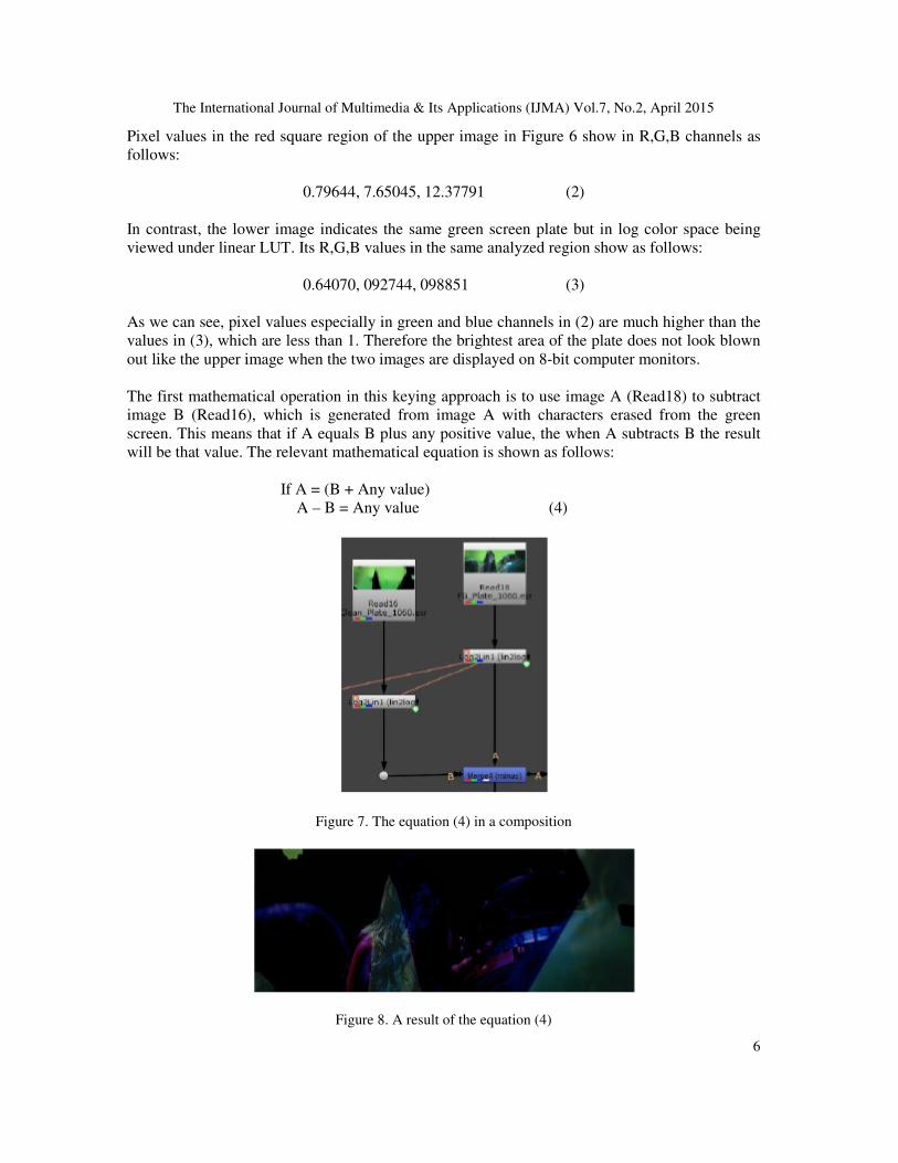
The first mathematical operation in this keying approach is to use image A (Read18) to subtract
image B (Read16), which is generated from image A with characters erased from the green
screen. This means that if A equals B plus any positive value, the when A subtracts B the result
will be that value. The relevant mathematical equation is shown as follows:
If A = (B + Any value)
A – B = Any value (4)
Figure 7. The equation (4) in a composition
Figure 8. A result of the equation (4)

The International Journal of Multimedia & Its Applications (IJMA) Vol.7, No.2, April 2015
7
From this step, further processes will be divided into two branches in order to improve the final
result.
Step one:
Following the main stream down in Figure 5, there are three additional steps after the equation
(4) shown in Figure 7: these are to decrease the overall saturation, to increase the contrast value
and to bring down the overall luminance. The improved result is shown below:
Figure 9. Shows the improved result
Step two:
The result of (4), shown in Figure 8 generated some negative values in the background and
shadow areas of the characters in some areas. In order to create a matte based on this result,
weneed to convert those negative values back to positive. In mathematics, the absolute value |x|
of a real number x is the non-negative value of x without regard to its sign. Namely, |x| = x for a
positive x, |x| = −x for a negative x, and |0| = 0 [10]. For instance, the absolute value of 2 is 2, and
the absolute value of −2 is also 2. As a result, if we use the result which contains minus values in
the R,G,B channels to subtract another image with 0,0,0 pixel values in R,G,B then the absolute
value of the result will become positive. A simple equation is shown below:
Abs(A-B) (5)
A visual result of this equation is shown in Figure 10.
Figure 10. A visual result of equation (5)

The International Journal of Multimedia & Its Applications (IJMA) Vol.7, No.2, April 2015
8
An existing equation for converting a color image into a gray scale image is used in Figure 11 to
generate a black/white scale matte image based on the result of equation (5). The equation and its
result is laid out as follows:
Gray = (r*0.299) + (g*0.587) + (b*0.114) (6)
Figure 11. Shows a visual result of equation (6)
As a final combining result of step one and two, we use the result of Figure 11 as an alpha to
decrease the overall saturation of Figure 9. The result is shown below in Figure 12, which will be
added onto a background plate.
Figure 12. A final combining result of step one and two with negative pixel values in R,G,B channels
According to the mathematical equation below, image A with minus values plus image B is
shown in Figure 13.
(-A) + B = B + (-A) = B –A (7)
Figure 13. Image A (left) with minus pixel values plus image B (right)
Figure 14 below shows the visual result of the equation (7) in log color space being viewed on an
8-bit computer monitor under sRBG LUT.

The International Journal of Multimedia & Its Applications (IJMA) Vol.7, No.2, April 2015
9
Figure 14. A final visual result of equation (7)
Before the result is used as a final background plate for a composition, the log color space needs
to be converted back to linear color space and the pixel values returned to floating point. As we
can see from the result below, the character edge details, especially hair details, have been baked
into the background.
Figure 15. The final result converted from log to linear color space
The last step of this approach of green screen keying is to generate a separate matte from the
original green screen plate and add it on top of the background plate shown in Figure 15.
Figure 16. Above image shows a matte generated from the original green screen plate

The International Journal of Multimedia & Its Applications (IJMA) Vol.7, No.2, April 2015
10
The final finished composition created by using this approach is shown below:
Figure 17. Shows a final composition
The following images compare three results, image A shows the result created by using the
approach in the ZZ_Keyer node. Image B shows the result generated by other keying methods.
For comparative purposes, image C shows the result of image B subtracted from image A. From
the result, we can clearly see how much of the detail has been restored, especially around the
edges of the characters.
Figure 18. A comparison of the results
As this is a complex process, the following image shows a simplified version of this approach.
The ZZ_Keyer node is connected to three plates – Foreground, Background and Backing Colorin
order to accomplish all the mathematical calculations necessary.

The International Journal of Multimedia & Its Applications (IJMA) Vol.7, No.2, April 2015
11
Figure 19. A simplified version of this approach
A final composition is shown in Image A (left) in Figure 20. In order to demonstrate how much
detail, especially hair detail is retained through this approach, image B (right) is a subtraction
result from another composition result, which was created by using a traditional keying method.
Figure 20. The left image shows a final composition resulting from using this approach. The right image
indicates the improved quality of hair detail
4. CONCLUSIONS
This study has briefly covered the historical background of using green or blue screen footage in
feature films, also, the film industry format which retains higher value footage as well as a typical
way of creating mattes in the visual effects industry were also discussed. In order to provide a
better understanding of two key factors for green or blue screen keying by using this keying
approach, a detailed analysis of chroma subsampling and some typical types of subsampling
available for film and digital data encoding, such as 4:4:4 Y’CbCr, 4:2:2 were also explained. As
a second key factor of green or blue screen keying for this approach, a series of principles of
linear and log color space were mathematically analyzed as well. In the process of analyzing this
newly demonstrated method of green screen keying, a pair of 10-bit DPX images in linear and
log color spaces viewed on an 8-bit computer monitor under sRGB LUT were presented. For a
full understanding of this keying method, a number of core mathematical equations integral to
this approach were also laid out. For instance in (4), the equation explained the first important
step of this approach. Two further steps were introduced separately with results and related

The International Journal of Multimedia & Its Applications (IJMA) Vol.7, No.2, April 2015
12
equations were clearly demonstrated in each section. For example, step two explained three key
equations: Abs(A-B), Gray = (r*0.299) + (g*0.587) + (b*0.114) and (-A) +B = B + (-A) = B – A.
An image eventually demonstrated the result of this approach in Figure 15. In addition, there
were examples of two extra results of a final composition and a comparative result of an
improvement through using this method exhibited in Figure 17 and Figure 18. A simplified
version with a premade node was demonstrated in Figure 19. In addition to Figure 19, a final
compositing result as well as the result of an improvement in hair detail were also given in Figure
20.
ACKNOWLEDGEMENTS
The author would like to thank the following organizations and people: The Moving Picture
Company, London. Cinesite Visual Effects, London. CPDA, University of Greenwich. Ms
Suzanne Moxhay, Ms Hey Kyoung Kim and many other people, who helped with this study.
REFERENCES
[1] Richard, J (1994) “RKO Film Grosses: 1931-1951”, Historical Journal of Film Radio and Television
14, 1, pp55.
[2] GORBACHEV, B. K (1961). Tekhnika kombinirovannykh s’’emok. Moscow, 2nd ed.
[3] Snider., David., Glenn K., Ken C., and Michael M (1993) Digital Moving-Picture Exchange: File
Format and Calibration, SMPTE Journal, pp712-714.
[4] Mike. S (2011). The Art of Digital Color. Fxfuide
[5] Mark, C.V., Craig, B (2002). The Invisible Art: The Legends of Movie Matte Painting. Chronicle
Books, pp33.
[6] Livingstone, M (2002) The First Stages of Processing Color and Luminance: Where and What.
Vision and Art: The Biology of Seeing. New York: Harry N. Abrams, pp46–67.
[7] Chrles, P (2003). Digital Video and HDTV: Algorithms and Interfaces. Morgan-Kaufmann. 24,
pp291-292.
[8] Larry, G., and eugene, E (2007). GPU Gems 3. Chapter 24.
[9] Lee, L (2010). Professional Digital Compositing. Wiley Publishing, Inc., Indianapolis, pp47-51.
[10] Hazewinkel, M (2001). Absolute value, Encyclopedia of Mathematics, Springer
AUTHORS
Dr Jin Zhi has a very wide higher education background in tradition art, design
and digital moving images, film production as well as film visual effects and 3D
CGI. Jin is currently working at Creative Professions & Digital Arts, University of
Greenwich. In the past 10 years, Jin worked in various VFX studios including The
Moving Picture, London and Cinesite Kodak Visual Effects. Meanwhile, Dr Jin
also worked as a visiting lecturer in a number of universities in the UK as well as
South Korea such as University of Westminster, London and Konkuk University
in Seoul, South Korea. As a film VFX Compositor, Jin’s visual effects works are
included in following commercial feature films: Prometheus (2012), Wrath of the Titans (2012), John
Carter (2012), Harry Potter and the Deathly Hallows: Part 2 (2012). Jin’s expertise and research interests
widely covered in different areas in film & television post-production, especially film digital compositing,
film & TV visual effects productions, creating 3D CG elements for feature films as well as digital moving
image design, etc. In addition, Dr Jin has been certified as a Nuke Trainer by the Foundry UK in 2015.