a new algorithm for rotation detection in iris pattern
TRANSCRIPT

HAL Id: hal-01551719https://hal.inria.fr/hal-01551719
Submitted on 30 Jun 2017
HAL is a multi-disciplinary open accessarchive for the deposit and dissemination of sci-entific research documents, whether they are pub-lished or not. The documents may come fromteaching and research institutions in France orabroad, or from public or private research centers.
L’archive ouverte pluridisciplinaire HAL, estdestinée au dépôt et à la diffusion de documentsscientifiques de niveau recherche, publiés ou non,émanant des établissements d’enseignement et derecherche français ou étrangers, des laboratoirespublics ou privés.
Distributed under a Creative Commons Attribution| 4.0 International License
A New Algorithm for Rotation Detection in Iris PatternRecognition
Krzysztof Misztal, Jacek Tabor, Khalid Saeed
To cite this version:Krzysztof Misztal, Jacek Tabor, Khalid Saeed. A New Algorithm for Rotation Detection in IrisPattern Recognition. 11th International Conference on Computer Information Systems and IndustrialManagement (CISIM), Sep 2012, Venice, Italy. pp.135-145, �10.1007/978-3-642-33260-9_11�. �hal-01551719�

A new algorithm for rotation detection in irispattern recognition
Krzysztof Misztal1,2, Jacek Tabor2, and Khalid Saeed1
1 AGH University of Science and TechnologyFaculty of Physics and Applied Computer Science
al. A. Mickiewicza 30, 30-059 Krakow, [email protected], [email protected]
2 Jagiellonian UniversityFaculty of Mathematics and Computer Science
Lojasiewicza 6, 30-348 Krakow, [email protected]
Abstract. A new method for finding the rotation angle in iris imagesfor biometric identification is presented in this paper. The proposed ap-proach is based on Fourier descriptors analysis and algebraic propertiesof vector rotation in complex space.
Keywords: iris pattern recognition, rotation estimation, rotation recov-ery, Fourier descriptors
1 Introduction
The iris is an important candidate for the source of the unique human populationcharacteristics. It is very stable over time – the iris is determined during the firstyears of our lives and does not change until the death. Moreover, the study showsthe iris structure is minimally dependent on our genes and allows to identify evenidentical twins. In addition, the modern iris biometrics systems are fast and havea high accuracy verification.
In light of the above, it seems that the iris is ideal for biometrics. However,the iris recognition process is complex and the construction of a complete systemrequires addressing a number of problems. The current approaches to iris patternrecognition include: the Gabor wavelet approach by Daugman [2], the Laplacianparameter approach by Wildes et al. [9], zero-crossings of the wavelet transformat various resolution levels by Boles et al. [1], the Independent Component Anal-ysis approach by Huang et al. [6], the texture analysis using multi-channel Gaborfiltering and wavelet transform by Zhu et al. [10], and many others ideas. Eachmethod has its own advantages and disadvantages.
Let us focus our attention on the classical John Daugman algorithm [3] – themost popular approach to individual identification by iris pattern recognition.and discuss how the algorithm copes with rotations. Let us start with the ex-planation and role of iris rotation angle. Fig. 1 present rotated and non-rotatediris images. When capturing iris images, most systems seek to achieve the same

(a) (b)
Fig. 1: Iris images: original (non-rotated) and rotated (23 degree).
environmental conditions and the position of the face. Under some assumed re-strictions the obtained images provide the highest reliability of identificationmethods. However, these methods are not comfortable for the users. The systemproposed by Daugman detects the rotation angle by ”brute force”, i.e., by test-ing all accessible angles and selects the best of them. However, such a way, aswe will show later is not optimal in practice. Our aim in this paper is to presentalternative approach to this method. The method determines the rotation angledirectly. Based on this knowledge we hope to develop a more efficient algorithmto identify individuals.
In the first part of our work we briefly describe the classical Daugman algo-rithm. In the next chapter we will focus on the problem of detecting the rotationangle of the iris image. Then we describe the rotation angle estimation algo-rithm using Fourier transform. Further considerations will include constructionof our algorithm. The last part of the work contains numerical experiments thatdemonstrate how our rotation angle estimation algorithm is relatively insensitiveto both the eye and the camera:
– rotation,– contrast modification,– illumination level modification,– blurring,– sharpening.
This makes it suitable to be used even in the first stage of preprocessing imagesfor the algorithm of individual verification.
2 Iris code matching algorithms survey
In this section we describe the main stages in the iris pattern recognition algo-rithm proposed by John Daugman [3].
After positive iris detection on an image and automatic segmentation we canmatch the iris region. To simplify, we assume we can describe the iris using onlytwo circles – the arcs of the upper and lower eyelids are invisible on the surface
of the iris. The next step in the iris pattern recognition algorithm performs thenormalization process, which includes conversion of the iris annulus into therectangular sized fixed image.
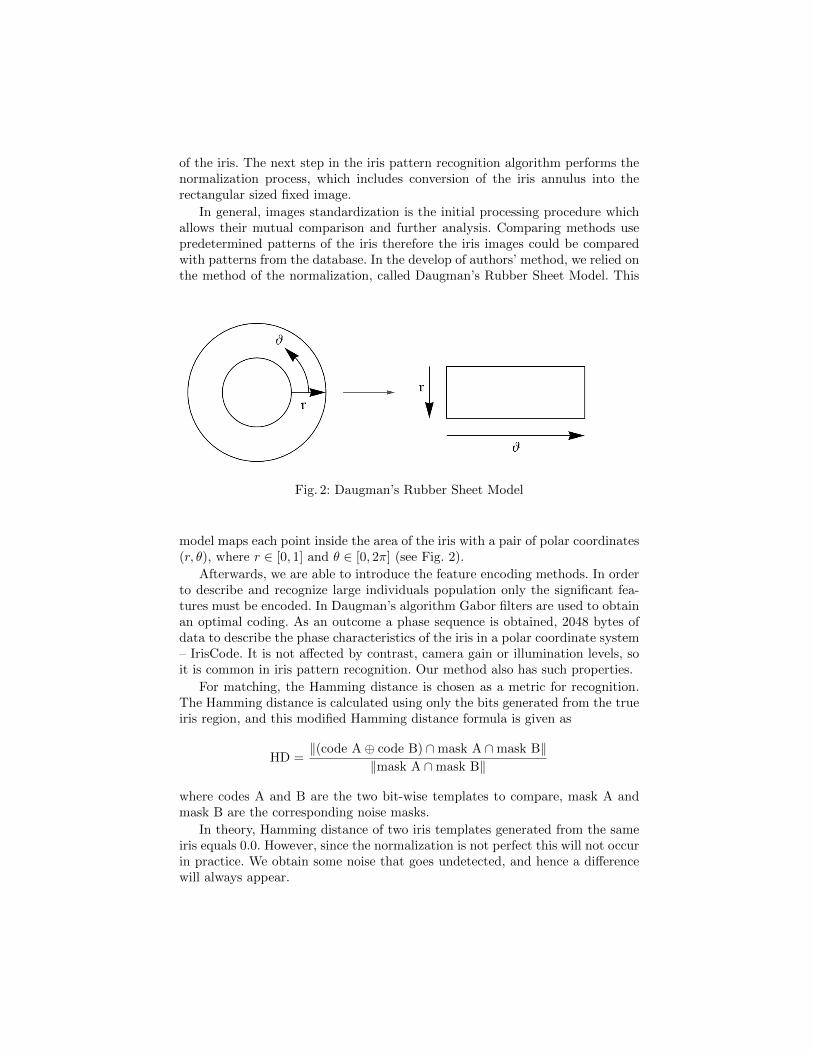
In general, images standardization is the initial processing procedure whichallows their mutual comparison and further analysis. Comparing methods usepredetermined patterns of the iris therefore the iris images could be comparedwith patterns from the database. In the develop of authors’ method, we relied onthe method of the normalization, called Daugman’s Rubber Sheet Model. This
Fig. 2: Daugman’s Rubber Sheet Model
model maps each point inside the area of the iris with a pair of polar coordinates(r, θ), where r ∈ [0, 1] and θ ∈ [0, 2π] (see Fig. 2).
Afterwards, we are able to introduce the feature encoding methods. In orderto describe and recognize large individuals population only the significant fea-tures must be encoded. In Daugman’s algorithm Gabor filters are used to obtainan optimal coding. As an outcome a phase sequence is obtained, 2048 bytes ofdata to describe the phase characteristics of the iris in a polar coordinate system– IrisCode. It is not affected by contrast, camera gain or illumination levels, soit is common in iris pattern recognition. Our method also has such properties.
For matching, the Hamming distance is chosen as a metric for recognition.The Hamming distance is calculated using only the bits generated from the trueiris region, and this modified Hamming distance formula is given as
HD =‖(code A⊕ code B) ∩mask A ∩mask B‖
‖mask A ∩mask B‖
where codes A and B are the two bit-wise templates to compare, mask A andmask B are the corresponding noise masks.
In theory, Hamming distance of two iris templates generated from the sameiris equals 0.0. However, since the normalization is not perfect this will not occurin practice. We obtain some noise that goes undetected, and hence a differencewill always appear.

2.1 Daugman’s approach – brute force matching
The following method, suggested by Daugman, corrects the misalignment in thenormalized iris pattern. In order to cope with rotational inconsistencies, whenthe Hamming distance of two templates is calculated, one template is shifted toone bit left and right. Then the Hamming distance values are calculated. Thisbit offset in the horizontal direction corresponds to the primary market areaof the iris angle indicated by the Rubber Sheet Model. As for the iris distancewe choose only the lowest, which corresponds to the best match between twotemplates.
Fig. 3: The shifting process for one shift left and right.
The number of bits transferred during each shift by two times the number offilters used, since each filter will generate two bits of information from one pixelnormalized region. The real number of changes necessary to normalize rotationalinconsistencies will be determined by the maximum angle difference between twopictures of the same eye. One change is defined as one shift to the left, then oneshift to the right. The example of shifting process is presented in Fig. 3.
In practice, when we configure the algorithm, we fix the maximum numberof shifts to the left and to the right. This brute force rotation angle estimationby comparisons is made with each element in the database – this is the maindisadvantage of this method.

2.2 Authors’ Approach: Fourier Descriptor Extended Method –angle calculation
Discrete Fourier Transform (DTF). For convenience of the reader and toestablished notation we recall the basic definitions of DFT. DFT transforms(c0, . . . , cN−1) ∈ Cn into a sequence (C0, . . . , CN−1) of complex numbers usingthe frequency domain representation:
Ck =1√N
N−1∑n=0
cn exp
(− i2πnk
N
), 0 ≤ k ≤ N − 1,
where cn = an + ibn, for k = 0, . . . , N − 1. This representation is widely used indata compression [7], partial differential equations, data mining, etc.
It is easy to see that
C0 =1√N
N−1∑n=0
cn
and
C1 =1√N
N−1∑n=0
cn exp
(− i2πn
N
). (1)
Remark 1. Fourier descriptors can be used to capture the main details of aboundary. This property is valuable because the coefficients usually keep theshape information. Thus they can be used as the basis for differentiating betweendistinct boundary shapes [5].
(a) (b)
Fig. 4: Example of two shapes with digital boundary. The rotation of the secondone does not allow to estimate angle of rotation.

This allows recovering the rotation for images with ordinary boundaries (seeFig. 4). However, it is useless in the case of rotation of the circles. Moreover, itcan be affected by image modification like contrast correction, gamma correction,blurring, etc.
The Fourier descriptor approach to rotation detection in iris patternrecognition. In this section we present how to recover the rotation angle us-ing the modified idea of Fourier transform with vector angle calculation. Themethod from the above remark is not suitable in this situation, because the irisis represented as concentric circles and their rotations cannot be detected byboundary positions testing.
Assume that after using Daugman’s Rubber Sheet Model we obtain twonormalized iris I and IR for original and rotated images respectively. Images areassumed to be in gray-scale and each pixel in the image is coded by a numberfrom the set {0, . . . , 255}. Next, we resize the images to obtain the same size, forexample we set the new size to 8× 256 (image height × width).
As an outcome we obtain two matrices
I = (ckn)k,n ∈M8×256(IR),
IR = (cRkn)k,n ∈M8×256(IR).
Next, we construct the vectors of features describing I and IR by Fourier de-scriptors. For each row of these matrices we calculate the first Fourier descriptoraccording to equation (1)
Ck =1
16
255∑n=0
ckn exp
(− i πn
128
), for k = 1, . . . , 8,
CRk =1
16
255∑n=0
cRkn exp
(− i πn
128
), for k = 1, . . . , 8.
We putx = (C1, . . . , C8), xR = (CR1 , . . . , C
R8 ).
Under the considerations of subsection about Fourier Descriptor Method, we getthat those vectors are in the form x = eiϕv, xR = w, for some v, w ∈ C8.
Remark 2. The problem of finding the angle of rotation in the iris images canbe formulated mathematically as follows.
Let non-trivial vectors v, w ∈ C8 be fixed. We are looking for the minimumof the function f :
fv,w : [0, 2π] 3 ϕ→ ‖eiϕv − w‖2 ∈ IR+.
These functions describe the rotation one of the vectors relatively to the secondone. We want to reduce the vectors to the same one-dimensional linear subspace.This will reduce the difference between them.

After simple transformation we get
fv,w(ϕ) = ‖v‖2 + ‖w‖2 − (eiϕ〈v, w〉+ eiϕ〈v, w〉)= ‖v‖2 + ‖w‖2 − 2<(eiϕ〈v, w〉).
It is easy to see that the minimum is reached when the value of
<(eiϕ〈v, w〉)
is the largest. A trivial observation shows that
<(eiϕ〈v, w〉) ≤ |eiϕ〈v, w〉| = |〈v, w〉|, for ϕ ∈ [0, 2π].
Consequently, we get eiϕ = 〈v, w〉/|〈v, w〉|, since z · z = |z|2 for z ∈ C and|eiϕ| = 1. Thus the minimum of the function f is reached for
ϕ = Arg〈v, w〉|〈v, w〉|
. (2)
Thus, with a description by a vector of features, we can find the angle by whichthe iris has been rotated.
Therefore, we can apply observation from previous section and by equation(2) we obtain
ϕ = Arg〈x, xR〉|〈x, xR〉|
, (3)
where ϕ is the desired angle.Summarizing, our approach to the problem of rotation angle estimation is
stated as follows:
1. perform Daugman’s Rubber Sheet Model standardization for I and IR (weuse rubber sheets of 8× 256);
2. calculate Fourier Transform for each row of rubber sheets;3. select the first Fourier descriptor from each rubber’s row and build the vec-
tors x and xR;4. estimate angle of rotation using equation (3);5. compare irises by Hamming distance using estimated angle.
The above steps link properties of the Fourier transform and the algebraic cal-culations. The computation is based on simple mathematical operations whichmake it easy for implementation.
3 Application in iris matching
In the last part of this work we present the comparison of classical Daugman’sshifting method with our algorithm. Moreover, we make some experiments withnoising and other ”destruction” of information on iris images (ex. blur, gammacorrection, sharpen) and examine the algorithm under such circumstances [8].
We prepare implementation of Daugman’s iris recognition algorithm basedon [3] and [2]. Besides we extend this application by adding the implementationof our method.

3.1 Comparison between classical and authors’ method in rotationangle detection.
Firstly, we compare the efficiency of shifting method with our method. Table 1contains comparison between the classical method and ours.
We evaluate IrisCode for rotated (for angle 0, . . . , 9 degrees) and non-rotatedimages. Then we run shifting method to see what angle (column Rec.) was chosenand what the value of Hamming distance (column HD) is. In this case IrisCodeevaluated for rotated iris image was compared with shifted original IrisCode inmaximum 10 shifts. Next, we use our method which estimates rotation angle
Table 1: Comparison of angle detection in classical methods with shifts andauthors’ method
Classical Authors’Angle Rec. HD Rec. HD
0 0 0 0.0 01 0 0 0.0 02 1 0 1.4 03 3 0 2.8 04 3 0 2.8 05 4 0 4.2 06 6 0 5.6 07 6 0 5.6 08 7 0 7.0 09 8 0 8.4 0
(column Rec.), and then the estimated angle was rounded to the nearest integerand used to generate shifted IrisCode. The obtained distance is presented incolumn HD.
The experiment results show that our method gives the same angle as thebrute force method, with the advantage that calculations were performed faster.
3.2 Sensitivity to image modifications
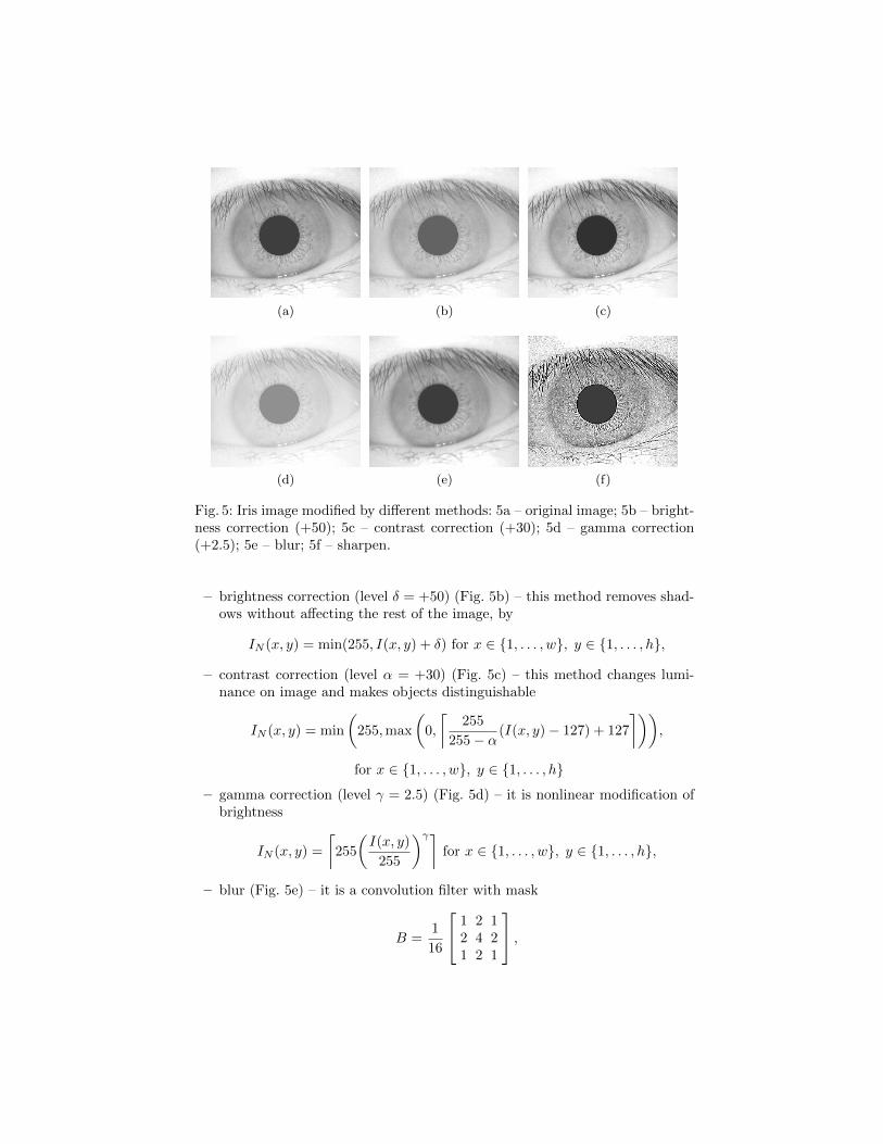
During the second experiment we want to check if our method is insensitive toimage destruction. Fig. 5 presents images used in this experiment. But beforewe present experiment details let us put some notations.
Let I denote image of size w × h pixels (width × height) – it is a matrix,so I ∈ {0, . . . , 255}w×h for gray-scale image. Then I(x, y) for x ∈ {1, . . . , w},y ∈ {1, . . . , h} denotes colors value at position (x, y) on image. By IN we denotethe new image (output image) created by modifying the input image I.
We can now proceed in explaining the original image (Fig. 5a) modificationdescriptions. We use the following methods:
(a) (b) (c)
(d) (e) (f)
Fig. 5: Iris image modified by different methods: 5a – original image; 5b – bright-ness correction (+50); 5c – contrast correction (+30); 5d – gamma correction(+2.5); 5e – blur; 5f – sharpen.
– brightness correction (level δ = +50) (Fig. 5b) – this method removes shad-ows without affecting the rest of the image, by
IN (x, y) = min(255, I(x, y) + δ) for x ∈ {1, . . . , w}, y ∈ {1, . . . , h},
– contrast correction (level α = +30) (Fig. 5c) – this method changes lumi-nance on image and makes objects distinguishable
IN (x, y) = min
(255,max
(0,
⌈255
255− α(I(x, y)− 127) + 127
⌉)),
for x ∈ {1, . . . , w}, y ∈ {1, . . . , h}
– gamma correction (level γ = 2.5) (Fig. 5d) – it is nonlinear modification ofbrightness
IN (x, y) =
⌈255
(I(x, y)
255
)γ⌉for x ∈ {1, . . . , w}, y ∈ {1, . . . , h},
– blur (Fig. 5e) – it is a convolution filter with mask
B =1
16
1 2 12 4 21 2 1
,

used to reduce noise and details information on image. In this case linearfiltering with a mask of size 3× 3 is given by the expression
IN (x, y) =
1∑s=−1
1∑t=−1
B(s, t)I(x+ s, y + t).
To generate full filtered image this equation should be applied for x ∈{1, . . . , w} and y ∈ {1, . . . , h} (see [5]).
– sharpen (Fig. 5f) – it is a convolution filter with a mask −1 −1 −1−1 9 −1−1 −1 −1
.Sharpens the image making it look crisper and making the edges in the imagemore distinct.
Table 2: Angle detection in different image modifications (angle is given in de-grees).
AngleMethod 5 14 23 47 76
Rec. Error Rec. Error Rec. Error Rec. Error Rec. Error
None 4.22 0.78 12.66 1.34 22.50 0.50 46.41 0.59 75.94 0.06Brightness 4.22 0.78 12.66 1.34 22.51 0.49 46.41 0.59 75.94 0.06Contrast 3.99 1.01 12.43 1.57 22.27 0.73 46.18 0.82 75.71 0.29Gamma 3.98 1.02 12.41 1.59 22.26 0.74 46.16 0.84 75.70 0.30
Blur 3.69 1.31 11.99 2.01 21.87 1.73 45.69 1.31 75.13 0.87Sharpen 3.66 1.34 13.72 0.28 23.10 0.10 47.92 0.92 77.83 1.83
Table 3: Angle detection in different image modifications (angle is given in de-grees) obtained by classical shifting.
AngleMethod 5 14 23 47 76
Rec. Error Rec. Error Rec. Error Rec. Error Rec. Error
None 5 0 14 0 23 0 47 0 76 0Brightness 0 5 10 4 0 23 38 9 8 68Contrast 0 5 10 4 0 23 38 9 8 68Gamma 0 5 11 3 1 22 38 9 8 68
Blur 0 5 13 2 3 20 60 13 30 46Sharpen 0 5 10 4 0 23 38 9 8 68

Table 2 summarizes the values of estimated angles with error level obtainedby our method. Table 3 contains angles recovered by classical Daugman method.The error level in both examples suggests that our method is not affected by theproposed image factors.
4 Conclusions
The iris identification and verification process is complex and the constructionof a complete system requires addressing a number of problems. One of the mostimportant and most difficult ones is that of detecting the rotation angle of the irisimage. The authors have introduced a new method to solve this problem basedon simple mathematical operations which have made it easy for implementation.Fourier transform and some algebraic calculations are utilized to work out analgorithm of high success rate whose performance is presented in this work. Ithas described and shown the rotation angle estimation using Fourier transform.The numerical experiments have demonstrated how the authors algorithm isrelatively insensitive to both the eye and the camera relative to rotation, contrastchanges, illumination level and other factors that usually affect the image underprocessing.
Acknowledgment
The work is supported by AGH University of Science and Technology, Krakow(grant no. 11.11-220-01).
References
1. Boles, WW and Boashash, B.: A human identification technique using images of theiris and wavelet transform. Signal Processing, IEEE Transactions on, 46(4):1185–1188 (1998).
2. Daugman, J.: High confidence visual recognition of persons by a test of statisticalindependence. Pattern Analysis and Machine Intelligence, IEEE Transactions on,15(11):1148–1161 (1993).
3. Daugman, J.: How iris recognition works. Circuits and Systems for Video Technol-ogy, IEEE Transactions on, 14(1):21–30 (2004).
4. Elshoura, S. M. and Megherbi, D. B.: A new rotation estimation and recovery al-gorithm. Computer Communication Control and Automation (3CA), 2010 Interna-tional Symposium on, 1, 411–414 (2010).
5. Gonzalez, R. C. and Woods, R. E.: Digital Image Processing. Prentice Hall, UpperSaddle River, NJ (2002).
6. Huang, Y.P. and Luo, S.W. and Chen, E.Y.; An efficient iris recognition system Ma-chine Learning and Cybernetics, 2002. Proceedings. 2002 International Conferenceon, 1:450–454 (2002).
7. Salomon, D.: Data compression: the complete reference Springer-Verlag New YorkInc (2007).

8. Tomeo-Reyes, I. and Liu-Jimenez, J. and Rubio-Polo, I. and Redondo-Justo, J. andSanchez-Reillo, R.: Input images in iris recognition systems: A case study. SystemsConference (SysCon), 2011 IEEE International, 501–505 (2011).
9. Wildes, R. P.: Iris recognition: an emerging biometric technology. Proceedings ofthe IEEE, 85(9):1348–1363 (1997).
10. Zhu, Y. and Tan, T. and Wang, Y.: Biometric personal identification based on irispatterns. Pattern Recognition, 2000. Proceedings. 15th International Conference on,2:801–804 (2000).