a new concept of volumetric error analysis of machine ... in the volumetric error analysis....
TRANSCRIPT
Home
X
Spindle
Cutter
Guideway
Ballscrew Sensor Axis
L
Cutting Axis
Cutting point
Cutter
Work table Scale
GuidewayBallscrew
Reader head
X
Y
ZθZ
θY
θX
LX
LYLZ
and Z are the coordinates of current cutting point, defined by offsets. For different structure configurations of machine tools, the effective offsets have to be found. It is seen that the deviation of the cutting point in space due to angular errors are proportionally enlarged by the coordinate where the cutter is locating. The geometrical relationship between the cutter point and its coordinate can be illustrated in Fig. 1 in which the sensor point is not related. In other words, the Abbé offset is not considered in the volumetric error analysis. Physically, it is not correct.
Fig. 1 Geometrical relationship of machine tool 2.2 Proposed method
According to Abbé principle, the position error of cutter location is calculated by the multiplication of the Abbé offset and the angular error, as shown in Fig. 2 in 2D view. The guideway is non-straight and induces the pitch error (θ) of the stage that further generates the positioning error (δ) of the cutting point proportional to the amount of Abbé offset (L) from the sensor point. It results in δ = L×θ, when θ is very small.
In the working volume, the cutting point error is the deviation in three directions, as shown in Fig. 3.
Fig. 2 Cutting point error due to Abbé error
Fig. 3 Abbé error in 3D space
Therefore, the corresponding volumetric error can be expressed by
L L
L LL L
z y y zxy z x x z
y x x yz
(3)
It is noted here that although Eq. (3) is similar to Eq.
(2) in its form, however, the actual Abbé offset is adopted in use instead of the cutter coordinate adopted in Eq. (2). In practice, the Abbé offset has to be identified in each type of machine tool. The total volumetric errors of a three-axis machine tool caused by angular errors are the summation of components in each axis.
3 Example
Figure 4 shows the structure of a precision milling machine to be investigated. The Z- axis is mounted on the rail of the Column (X-axis). The work table is driven in Y-axis. All axes are equipped with liner scales as position feedback sensors. In this figure, the cutter is offset from the scale’s read head, which is the sensor point in the Y-axis with three components: LxY(x), LyY(y) and LzY(z). These Abbé offsets are related to the instantaneous cutter position (x, y, z) and can be expressed by
( ) 0L x L xxY xY
( ) 0L y L yyY yY (4)
( ) 0L z L zzY zY
In this equation, LxY0 is the distance between the cutter and reader head of Y axis when the cutter is moved at x=0. This offset will be reduced when the cutter moves in the x-axis. Similar expression can be applied to LyY0 and LzY0. It can be seen, therefore, the actual Abbé offset is different from the coordinate of the cutter location, as expressed by Eq. (2).
LzY (z)LxY (x)
LyY (y)
Cutter
Scale reader
Fig. 4 Abbé offset of Y-axis motion
The 3rd International Conference on Design Engineering and Science, ICDES 2014 Pilsen, Czech Republic, September 1-3, 2014
Copyright © 2014, The Organizing Committee of the ICDES 2014
A New Concept of Volumetric Error Analysis of Machine Tools Based on Abbé Principle
Kuang-Chao FAN*1, Han-Ming YEN*2 and Kun-Ying LI*3
*1 Department of Mechanical Engineering National Taiwan University 1, Sec. 4, Roosevelt Road, Taipei 10617, TAIWAN [email protected]
*2 Department of Mechanical Engineering National Taiwan University 1, Sec. 4, Roosevelt Road, Taipei 10617, TAIWAN
[email protected] *3 Mechanical and Systems Lab Industrial Technology Research Institute 191, 38 Road, Taichung Industrial Park, Taichung 407678, TAIWAN [email protected]
Abstract
Abbé error is the inherent systematic error in all numerically controlled (NC) machine tools due to the fact that the displacement measuring axis is not in line with the cutting axis. Any angular error of the moving stage will result in the position offset from the commanded cutting point. The positioning error of any cutting point in space is called volumetric error. The angular error induced volumetric error, up to now however, is still considered with respect to the coordinate of the cutting point. In this paper, a new concept of deriving the volumetric error with respect to the Abbé offset of the cutting point is proposed. Experimental results verify the correctness of the proposed method. Keywords: machine tool, volumetric error, Abbé error, error compensation
1 Introduction Abbé error is the inherent systematic error in all
numerically controlled (NC) machine tools. Abbé principle is regarded as the first principle in the design of precision positioning stages, machine tools, and measuring instruments [1]. It defines that the measuring apparatus is to be arranged in such a way that the distance to be measured is a straight-line extension of the graduation used as a scale. Bryan further made a generalized interpretation with that if the Abbé principle is not possible in the system design, either the slideway that transfer the displacement must be free of angular motion or the angular motion data must be obtained to compensate the Abbé error by software [2, 3].
Nowadays, most commercial machine tools and CMMs still cannot comply with Abbé principle because the scale axis is always parallel and offset to the moving axis. Any angular error of the moving stage will result in the position offset from the commanded cutting point. The positioning error of any cutting point in space is called volumetric error, which is composed of linear error terms, angular error induced 3D Abbé error terms and squareness error induced
positional offset terms. Ever since Tlusty proposed the formulation of volumetric error of machine tool in 1980[4], all researchers and machine tool companies followed this equation to measure, formulate and compensate for the volumetric error of machine tools, for example, [5-7]. In this paper, a more physically sensible point of view is proposed to analyze the cause of volumetric error from Abbé principle. As a result, the Abbé error in the working volume can be fully compensated by experimental verification.
2 Volumetric error of machine tools 2.1 Existing method The volumetric error of machine tool is normally caused by three sources, namely the linear errors of the moving stage in each axis, angular error induced deviation of cutting point in the working volume and the deviation of cutting point due to non-perpendicularity of any two axes. Tlustly first proposed the generalized equation as [4] Volumetric error = Linear terms + Angular terms +
Squareness terms (1)
In Eq. (1), the linear terms refer to the positioning error and two straightness errors of each moving stage, the angular terms indicate the grown linear errors caused by angular errors of each moving stage the squareness term is caused by non-perpendicular motion of any two axes. In this study, only the angular term is concerned. The general expression of this term is given by Eq. (2). (2) In this equation, δx(i) refers to the deviation of the cutting point from its nominal point in x direction during i-direction motion and i=x, y, z; εx(i) denotes the angular error in x direction of i-direction motion; X, Y
( ) ( )0( ) 0 ( )
0( ) ( )
i iZ Yi Z X i
Y Xi i
x xy yz z
– 198 – – 199 –
The 3rd International Conference on Design Engineering and Science, ICDES 2014Pilsen, Czech Republic, August 31 – September 3, 2014

Home
X
Spindle
Cutter
Guideway
Ballscrew Sensor Axis
L
Cutting Axis
Cutting point
Cutter
Work table Scale
GuidewayBallscrew
Reader head
X
Y
ZθZ
θY
θX
LX
LYLZ
and Z are the coordinates of current cutting point, defined by offsets. For different structure configurations of machine tools, the effective offsets have to be found. It is seen that the deviation of the cutting point in space due to angular errors are proportionally enlarged by the coordinate where the cutter is locating. The geometrical relationship between the cutter point and its coordinate can be illustrated in Fig. 1 in which the sensor point is not related. In other words, the Abbé offset is not considered in the volumetric error analysis. Physically, it is not correct.
Fig. 1 Geometrical relationship of machine tool 2.2 Proposed method
According to Abbé principle, the position error of cutter location is calculated by the multiplication of the Abbé offset and the angular error, as shown in Fig. 2 in 2D view. The guideway is non-straight and induces the pitch error (θ) of the stage that further generates the positioning error (δ) of the cutting point proportional to the amount of Abbé offset (L) from the sensor point. It results in δ = L×θ, when θ is very small.
In the working volume, the cutting point error is the deviation in three directions, as shown in Fig. 3.
Fig. 2 Cutting point error due to Abbé error
Fig. 3 Abbé error in 3D space
Therefore, the corresponding volumetric error can be expressed by
L L
L LL L
z y y zxy z x x z
y x x yz
(3)
It is noted here that although Eq. (3) is similar to Eq.
(2) in its form, however, the actual Abbé offset is adopted in use instead of the cutter coordinate adopted in Eq. (2). In practice, the Abbé offset has to be identified in each type of machine tool. The total volumetric errors of a three-axis machine tool caused by angular errors are the summation of components in each axis.
3 Example
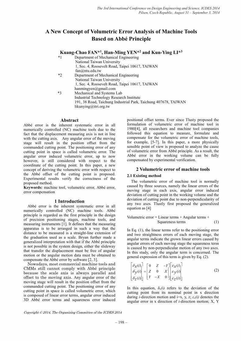
Figure 4 shows the structure of a precision milling machine to be investigated. The Z- axis is mounted on the rail of the Column (X-axis). The work table is driven in Y-axis. All axes are equipped with liner scales as position feedback sensors. In this figure, the cutter is offset from the scale’s read head, which is the sensor point in the Y-axis with three components: LxY(x), LyY(y) and LzY(z). These Abbé offsets are related to the instantaneous cutter position (x, y, z) and can be expressed by
( ) 0L x L xxY xY
( ) 0L y L yyY yY (4)
( ) 0L z L zzY zY
In this equation, LxY0 is the distance between the cutter and reader head of Y axis when the cutter is moved at x=0. This offset will be reduced when the cutter moves in the x-axis. Similar expression can be applied to LyY0 and LzY0. It can be seen, therefore, the actual Abbé offset is different from the coordinate of the cutter location, as expressed by Eq. (2).
LzY (z)LxY (x)
LyY (y)
Cutter
Scale reader
Fig. 4 Abbé offset of Y-axis motion
The 3rd International Conference on Design Engineering and Science, ICDES 2014 Pilsen, Czech Republic, September 1-3, 2014
Copyright © 2014, The Organizing Committee of the ICDES 2014
A New Concept of Volumetric Error Analysis of Machine Tools Based on Abbé Principle
Kuang-Chao FAN*1, Han-Ming YEN*2 and Kun-Ying LI*3
*1 Department of Mechanical Engineering National Taiwan University 1, Sec. 4, Roosevelt Road, Taipei 10617, TAIWAN [email protected]
*2 Department of Mechanical Engineering National Taiwan University 1, Sec. 4, Roosevelt Road, Taipei 10617, TAIWAN
[email protected] *3 Mechanical and Systems Lab Industrial Technology Research Institute 191, 38 Road, Taichung Industrial Park, Taichung 407678, TAIWAN [email protected]
Abstract
Abbé error is the inherent systematic error in all numerically controlled (NC) machine tools due to the fact that the displacement measuring axis is not in line with the cutting axis. Any angular error of the moving stage will result in the position offset from the commanded cutting point. The positioning error of any cutting point in space is called volumetric error. The angular error induced volumetric error, up to now however, is still considered with respect to the coordinate of the cutting point. In this paper, a new concept of deriving the volumetric error with respect to the Abbé offset of the cutting point is proposed. Experimental results verify the correctness of the proposed method. Keywords: machine tool, volumetric error, Abbé error, error compensation
1 Introduction Abbé error is the inherent systematic error in all
numerically controlled (NC) machine tools. Abbé principle is regarded as the first principle in the design of precision positioning stages, machine tools, and measuring instruments [1]. It defines that the measuring apparatus is to be arranged in such a way that the distance to be measured is a straight-line extension of the graduation used as a scale. Bryan further made a generalized interpretation with that if the Abbé principle is not possible in the system design, either the slideway that transfer the displacement must be free of angular motion or the angular motion data must be obtained to compensate the Abbé error by software [2, 3].
Nowadays, most commercial machine tools and CMMs still cannot comply with Abbé principle because the scale axis is always parallel and offset to the moving axis. Any angular error of the moving stage will result in the position offset from the commanded cutting point. The positioning error of any cutting point in space is called volumetric error, which is composed of linear error terms, angular error induced 3D Abbé error terms and squareness error induced
positional offset terms. Ever since Tlusty proposed the formulation of volumetric error of machine tool in 1980[4], all researchers and machine tool companies followed this equation to measure, formulate and compensate for the volumetric error of machine tools, for example, [5-7]. In this paper, a more physically sensible point of view is proposed to analyze the cause of volumetric error from Abbé principle. As a result, the Abbé error in the working volume can be fully compensated by experimental verification.
2 Volumetric error of machine tools 2.1 Existing method The volumetric error of machine tool is normally caused by three sources, namely the linear errors of the moving stage in each axis, angular error induced deviation of cutting point in the working volume and the deviation of cutting point due to non-perpendicularity of any two axes. Tlustly first proposed the generalized equation as [4] Volumetric error = Linear terms + Angular terms +
Squareness terms (1)
In Eq. (1), the linear terms refer to the positioning error and two straightness errors of each moving stage, the angular terms indicate the grown linear errors caused by angular errors of each moving stage the squareness term is caused by non-perpendicular motion of any two axes. In this study, only the angular term is concerned. The general expression of this term is given by Eq. (2). (2) In this equation, δx(i) refers to the deviation of the cutting point from its nominal point in x direction during i-direction motion and i=x, y, z; εx(i) denotes the angular error in x direction of i-direction motion; X, Y
( ) ( )0( ) 0 ( )
0( ) ( )
i iZ Yi Z X i
Y Xi i
x xy yz z
– 198 – – 199 –
Pitch, yaw and roll sensor
Optical scale
LXCutter
LY
LZ
Pitch
YawRoll
θZ
θY
XY
Z
θX
-10
0
10
20
30
40
50
0 10 20 30 40 50Posi
tioni
ng e
rror
(μm
)
Y position (mm)
Z Offset before compensation after compensation13cm17cm
HP5529
Tri-angle sensor
X
X
Z
Y
Z-offset
-40
-30
-20
-10
0
10
20
30
40
-50 -40 -30 -20 -10 0Po
sitio
ning
err
or (μ
m)
X position (mm)
Z Offset before compensation after compensation23cm27cm
Fig. 7 Machine tool with embedded sensor module
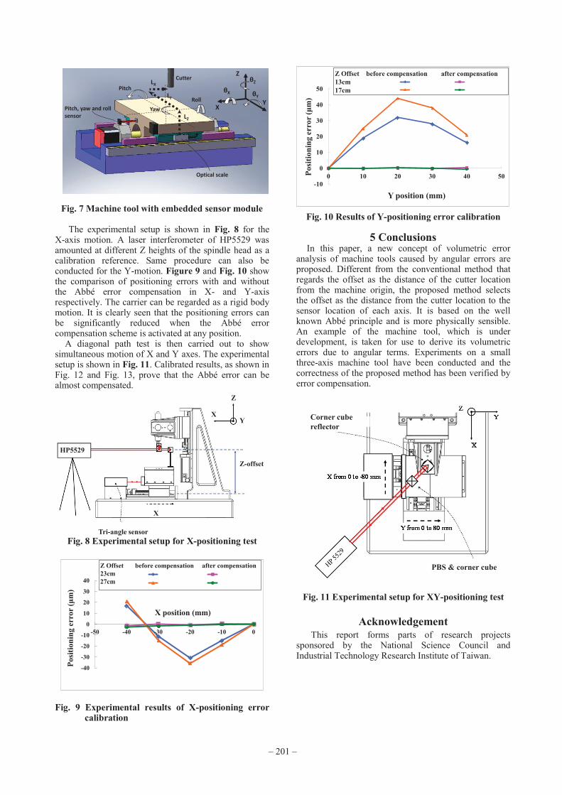
The experimental setup is shown in Fig. 8 for the X-axis motion. A laser interferometer of HP5529 was amounted at different Z heights of the spindle head as a calibration reference. Same procedure can also be conducted for the Y-motion. Figure 9 and Fig. 10 show the comparison of positioning errors with and without the Abbé error compensation in X- and Y-axis respectively. The carrier can be regarded as a rigid body motion. It is clearly seen that the positioning errors can be significantly reduced when the Abbé error compensation scheme is activated at any position.
A diagonal path test is then carried out to show simultaneous motion of X and Y axes. The experimental setup is shown in Fig. 11. Calibrated results, as shown in Fig. 12 and Fig. 13, prove that the Abbé error can be almost compensated.
Fig. 8 Experimental setup for X-positioning test
Fig. 9 Experimental results of X-positioning error calibration
Fig. 10 Results of Y-positioning error calibration
5 Conclusions In this paper, a new concept of volumetric error
analysis of machine tools caused by angular errors are proposed. Different from the conventional method that regards the offset as the distance of the cutter location from the machine origin, the proposed method selects the offset as the distance from the cutter location to the sensor location of each axis. It is based on the well known Abbé principle and is more physically sensible. An example of the machine tool, which is under development, is taken for use to derive its volumetric errors due to angular terms. Experiments on a small three-axis machine tool have been conducted and the correctness of the proposed method has been verified by error compensation.
Corner cube reflector
PBS & corner cube
Fig. 11 Experimental setup for XY-positioning test
Acknowledgement
This report forms parts of research projects sponsored by the National Science Council and Industrial Technology Research Institute of Taiwan.
The corresponding volumetric errors caused by this Y-axis motion can be derived from Eq. (3) and Eq. (4) as
zL
yLxL
yyyy
yy
yE
yEyE
zY
yY
xY
xy
xz
yz
z
y
x
0
0
0
0)()()(0)(
)()(0
)(
)()(
(5)
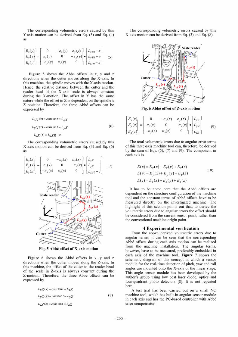
Figure 5 shows the Abbé offsets in x, y and z
directions when the cutter moves along the X-axis. In this machine, the spindle moves with the X-axis motion. Hence, the relative distance between the cutter and the reader head of the X-axis scale is always constant during the X-motion. The offset in Y has the same nature while the offset in Z is dependent on the spindle’s Z position. Therefore, the three Abbé offsets can be expressed by
( ) tanL x cons t LxX xX
( ) tanL x cons t LyX yX (6)
( ) 0L z L zzX zX
The corresponding volumetric errors caused by this X-axis motion can be derived from Eq. (3) and Eq. (6) as
zL
LL
xxxx
xx
xE
xExE
zX
yX
xX
xy
xz
yz
z
y
x
00)()()(0)(
)()(0
)(
)()(
(7)
LyX (y)
LxX (x)
LzX (z)
Cutter
Scale reader
Fig. 5 Abbé offset of X-axis motion
Figure 6 shows the Abbé offsets in x, y and z directions when the cutter moves along the Z-axis. In this machine, the offset of the cutter to the reader head of the scale in Z-axis is always constant during the Z-motion.. Therefore, the three Abbé offsets can be expressed by
( ) tanL x cons t LxZ xZ ( ) tanL y cons t LyZ yZ (8)
( ) tanL z cons t LzZ zZ
The corresponding volumetric errors caused by this X-axis motion can be derived from Eq. (3) and Eq. (8).
LzZ (z)
LxZ (x)LyZ (y)
Cutter
Scale reader
Fig. 6 Abbé offset of Z-axis motion
zZ
yZ
xZ
xy
xz
yz
z
y
x
L
LL
zzzz
zz
zE
zEzE
0)()()(0)(
)()(0
)(
)()(
(9)
The total volumetric errors due to angular error terms of this three-axis machine tool can, therefore, be derived by the sum of Eqs. (5), (7) and (9). The component in each axis is
( ) ( ) ( ) ( )( ) ( ) ( ) ( )
( ) ( ) ( ) ( )
x x x
y y y
z z z
E x E x E y E zE y E x E y E z
E z E x E y E z
(10)
It has to be noted here that the Abbé offsets are dependent on the structure configuration of the machine tool and the constant terms of Abbé offsets have to be measured directly on the investigated machine. The highlight of this section points out that, to derive the volumetric errors due to angular errors the offset should be considered from the current sensor point, rather than the conventional machine origin point.
4 Experimental verification From the above derived volumetric errors due to angular terms, it can be seen that the corresponding Abbé offsets during each axis motion can be realized from the machine installation. The angular terms, however, have to be measured, preferably embedded in each axis of the machine tool. Figure 7 shows the schematic diagram of this concept in which a sensor module for the real-time detection of pitch, yaw and roll angles are mounted onto the X-axis of the linear stage. This angle sensor module has been developed by the author’s group using low cost laser diode, optics and four-quadrant photo detectors [8]. It is not repeated here. A test trial has been carried out on a small NC machine tool, which has built-in angular sensor module in each axis and has the PC-based controller with Abbé error compensator.
– 200 – – 201 –
Pitch, yaw and roll sensor
Optical scale
LXCutter
LY
LZ
Pitch
YawRoll
θZ
θY
XY
Z
θX
-10
0
10
20
30
40
50
0 10 20 30 40 50Posi
tioni
ng e
rror
(μm
)
Y position (mm)
Z Offset before compensation after compensation13cm17cm
HP5529
Tri-angle sensor
X
X
Z
Y
Z-offset
-40
-30
-20
-10
0
10
20
30
40
-50 -40 -30 -20 -10 0
Posi
tioni
ng e
rror
(μm
)
X position (mm)
Z Offset before compensation after compensation23cm27cm
Fig. 7 Machine tool with embedded sensor module
The experimental setup is shown in Fig. 8 for the X-axis motion. A laser interferometer of HP5529 was amounted at different Z heights of the spindle head as a calibration reference. Same procedure can also be conducted for the Y-motion. Figure 9 and Fig. 10 show the comparison of positioning errors with and without the Abbé error compensation in X- and Y-axis respectively. The carrier can be regarded as a rigid body motion. It is clearly seen that the positioning errors can be significantly reduced when the Abbé error compensation scheme is activated at any position.
A diagonal path test is then carried out to show simultaneous motion of X and Y axes. The experimental setup is shown in Fig. 11. Calibrated results, as shown in Fig. 12 and Fig. 13, prove that the Abbé error can be almost compensated.
Fig. 8 Experimental setup for X-positioning test
Fig. 9 Experimental results of X-positioning error calibration
Fig. 10 Results of Y-positioning error calibration
5 Conclusions In this paper, a new concept of volumetric error
analysis of machine tools caused by angular errors are proposed. Different from the conventional method that regards the offset as the distance of the cutter location from the machine origin, the proposed method selects the offset as the distance from the cutter location to the sensor location of each axis. It is based on the well known Abbé principle and is more physically sensible. An example of the machine tool, which is under development, is taken for use to derive its volumetric errors due to angular terms. Experiments on a small three-axis machine tool have been conducted and the correctness of the proposed method has been verified by error compensation.
Corner cube reflector
PBS & corner cube
Fig. 11 Experimental setup for XY-positioning test
Acknowledgement
This report forms parts of research projects sponsored by the National Science Council and Industrial Technology Research Institute of Taiwan.
The corresponding volumetric errors caused by this Y-axis motion can be derived from Eq. (3) and Eq. (4) as
zL
yLxL
yyyy
yy
yE
yEyE
zY
yY
xY
xy
xz
yz
z
y
x
0
0
0
0)()()(0)(
)()(0
)(
)()(
(5)
Figure 5 shows the Abbé offsets in x, y and z
directions when the cutter moves along the X-axis. In this machine, the spindle moves with the X-axis motion. Hence, the relative distance between the cutter and the reader head of the X-axis scale is always constant during the X-motion. The offset in Y has the same nature while the offset in Z is dependent on the spindle’s Z position. Therefore, the three Abbé offsets can be expressed by
( ) tanL x cons t LxX xX
( ) tanL x cons t LyX yX (6)
( ) 0L z L zzX zX
The corresponding volumetric errors caused by this X-axis motion can be derived from Eq. (3) and Eq. (6) as
zL
LL
xxxx
xx
xE
xExE
zX
yX
xX
xy
xz
yz
z
y
x
00)()()(0)(
)()(0
)(
)()(
(7)
LyX (y)
LxX (x)
LzX (z)
Cutter
Scale reader
Fig. 5 Abbé offset of X-axis motion
Figure 6 shows the Abbé offsets in x, y and z directions when the cutter moves along the Z-axis. In this machine, the offset of the cutter to the reader head of the scale in Z-axis is always constant during the Z-motion.. Therefore, the three Abbé offsets can be expressed by
( ) tanL x cons t LxZ xZ ( ) tanL y cons t LyZ yZ (8)
( ) tanL z cons t LzZ zZ
The corresponding volumetric errors caused by this X-axis motion can be derived from Eq. (3) and Eq. (8).
LzZ (z)
LxZ (x)LyZ (y)
Cutter
Scale reader
Fig. 6 Abbé offset of Z-axis motion
zZ
yZ
xZ
xy
xz
yz
z
y
x
L
LL
zzzz
zz
zE
zEzE
0)()()(0)(
)()(0
)(
)()(
(9)
The total volumetric errors due to angular error terms of this three-axis machine tool can, therefore, be derived by the sum of Eqs. (5), (7) and (9). The component in each axis is
( ) ( ) ( ) ( )( ) ( ) ( ) ( )
( ) ( ) ( ) ( )
x x x
y y y
z z z
E x E x E y E zE y E x E y E z
E z E x E y E z
(10)
It has to be noted here that the Abbé offsets are dependent on the structure configuration of the machine tool and the constant terms of Abbé offsets have to be measured directly on the investigated machine. The highlight of this section points out that, to derive the volumetric errors due to angular errors the offset should be considered from the current sensor point, rather than the conventional machine origin point.
4 Experimental verification From the above derived volumetric errors due to angular terms, it can be seen that the corresponding Abbé offsets during each axis motion can be realized from the machine installation. The angular terms, however, have to be measured, preferably embedded in each axis of the machine tool. Figure 7 shows the schematic diagram of this concept in which a sensor module for the real-time detection of pitch, yaw and roll angles are mounted onto the X-axis of the linear stage. This angle sensor module has been developed by the author’s group using low cost laser diode, optics and four-quadrant photo detectors [8]. It is not repeated here. A test trial has been carried out on a small NC machine tool, which has built-in angular sensor module in each axis and has the PC-based controller with Abbé error compensator.
– 200 – – 201 –

Call for Entries of Students Workshop "Smart Designs for STRATASYS 3D Printing"
Student competition supported by TECNOTRADE OBRABECI STROJE s.r.o., CZ,
ICDES 2014, Parkhotel, Pilsen, Czech Republic, from Aug. 31 to Sept. 3, 2014
Design concept rules
Design a smart technical product model which can be produced only with a Stratasys 3D printer, in other words, the model that is possible to produce simply because it is additive manufacturing not removal machining. The model should satisfy the following assigned constraints:
- Maximum number of authors/designers is 1. Student status ID is required. - Technological constraints of a given Statatasys printer (using materials of FDM thermoplastic resin
and/or PolyJet resin). Applicant should select one material from FDM thermoplastics resin and/or (?) PolyJet resin.
- Maximum width, depth and height of a part are respectively 100 mm, 100 mm and 75 mm. - Maximum number of parts to be assembled is 3. As a matter of course, only one part model is welcome.
In this case, “a part” means a “at once” printed model without assembly, and in other words, “a part” is constructed by one STL file.
- If a mechanism (assembly), which has two or three parts, is going to be produced, there must be a gap of 0.15 mm between two contacting surfaces.
- 46 colour shades are available for the 3D printed model. Applicant should assign the part(s) colours(s). For example, when an applicant designs a model assembled by three parts, the applicant should assign one colour to one part.
- Stratasys logo should be installed in the outmost model surface and the 3D data of logo will be supplied by Tecnotrade Obrabeci Stroje s.r.o. Applicant will be able to download the 3D data of the logo through ICDES 2014 website http://www.jsde.or.jp/icdes2014/ .
-70
-60
-50
-40
-30
-20
-10
0
10
20
30
20 40 60 80 100 120?
)
Position (mm)
Before compensation
After compensation
Z=0 mm
Err
or (μ
m)
Fig. 12 Experimental results of XY-positioning error
calibration at height Z=0 mm
-80
-60
-40
-20
0
20
40
20 40 60 80 100 120
Err
or (μ
m)
Position (mm)
Before compensation
After compensation
Z=50 mm
Fig. 13 Experimental results of XY-positioning error
calibration at height Z=50 mm
References [1] Abbé, E., “Meßapparate für Physiker”, Zeitschrift
für Instrumentenkunde, Vol. 10, (1890), pp. 446–448.
[2] Bryan, J. B., “Abbé Principle Revisit: An Updated Interpretation,” Precision Engineering, Vol. 1, No. 3, (1979), pp. 129–132.
[3] Wright, D. A. and Bryan, J. B., “Letters”, Precision Engineering, Vol. 1, (1979), p2.
[4] Tlusty, J., Technology of Machine Tools, National Livermore National Laboratory, California, (1980), Supplement 1 “Testing of Accuracy of Machine Tool”.
[5] Ni, J. and Wu, S. M., “An On-line Measurement Technique for Machine Volumetric Error Compensation”, ASME J of Engineering for Industry, Vol. 115, No. 3, (1993), pp. 85–92.
[6] Okafor, A. C. and Ertekin, Y. M., “Derivation of Machine Tool Error Models and Error Compensation Procedure for Three Axes Vertical Machining Center using Rigid Body Kinematics”, International J of Machine Tools & Manufacture, Vol. 40, No. 8, (2000), pp. 1199–1213.
[7] Bringmann, B. and Knapp W., “Machine tool Calibration: Geometric Test Uncertainty Depends on Machine Tool Performance”, Precision Engineering, Vol. 33, No. 4, (2009), pp. 524-529.
[8] Fan, K.C., Wang, T.H., Wang, C.H. and Chen, H.M., “Development of an Abbé Error Compensator for NC Machine Tools”, Proc. 37th MATADOR Conf., Manchester, (2012), pp. 105-108.
Received on 23 December, 2013 Accepted on February 3, 2014
– 202 – – 203 –