a new digital image steganography based on center embedded
TRANSCRIPT
89
BULGARIAN ACADEMY OF SCIENCES
CYBERNETICS AND INFORMATION TECHNOLOGIES Volume 21, No 2
Sofia 2021 Print ISSN: 1311-9702; Online ISSN: 1314-4081
DOI: 10.2478/cait-2021-0021
A New Digital Image Steganography Based on Center Embedded
Pixel Positioning
Dedi Darwis1,2, Akmal Junaidi3, Dewi Asiah Shofiana3, Wamiliana4 1Doctoral at Faculty of Mathematics and Natural Science, Universitas Lampung, Lampung, Indonesia 2Faculty of Engineering and Computer Science, Universitas Teknokrat Indonesia, Lampung, Indonesia 3Department of Computer Science, Universitas Lampung, Lampung, Indonesia 4Department of Mathematics, Universitas Lampung, Lampung, Indonesia
E-mails: [email protected] [email protected]
[email protected] [email protected]
Abstract: In this study we propose a new approach to tackle the cropping problem in
steganography which is called Center Embedded Pixel Positioning (CEPP) which is
based on Least Significant Bit (LSB) Matching by setting the secret image in the
center of the cover image. The evaluation of the experiment indicated that the secret
image can be retrieved by a maximum of total 40% sequential cropping on the left,
right, up, and bottom of the cover image. The secret image also can be retrieved if
the total asymmetric cropping area is 25% that covered two sides (either left-right,
left-up or right-up). In addition, the secret image can also be retrieved if the total
asymmetric cropping area is 70% if the bottom part is included. If asymmetric
cropping area included three sides, then the algorithm fails to retrieve the secret
image. For cropping in the botom the secret image can be extracted up to 70%.
Keywords: Cover image, cropping, security, stego image, steganography.
1. Introduction
Steganography is a technical art on how to hide messages into other media, such as
image, text, audio, and video, that are all known as the steganographic cover.
Steganographic cover contains secret images in which can only be extracted by the
recipient. All digital files in bits can be the media of steganography [1-3].
Secret images in this research are images, whereas RGB (Red, Green, Blue)
images in Portable Network Graphics (PNG) format, which is a lossless compression
image format, were used as the media. The algorithm’s reliability determines the
image quality resulting from steganography in the embedding and extraction process
[4, 5]. There are two primary methods to test the image quality:
1. Fidelity, the ability to accurately process the image with no visual distortion
nor information loss by calculating the Peak-Signal to Noise-Ration (PSNR) [6, 7];

90
2. Robustness, the stego-analysis attack or image manipulation: attacking the
stego-image with image processing such as crop, blur, noise, rotate, etc., [8-10].
Image lacks the ability to preserve information when a stego-analysis attack
occurs, making robustness as the main concern in steganography [11, 12]. Cropping
is a type of image manipulation that will effectively distort the value of image pixels,
causing the hidden message in a stego-image to get corrupted [6, 13]. The crop
manipulation is effective since secret images are generally stored in a stego-image at
the very last bit of the image located in the top-left corner, which can be cropped
easily [14, 15].
Least Significant Bit (LSB) is a common technique in steganography that can
insert secret images to an image with no visual difference between the original image
and stego-image [16, 17]. The LSB method has been developed by implementing
Nine-Pixel Differencing and LSB Substitution that can increase the embedding
capacity while maintaining the image imperceptible as well as improving the fidelity
value. This development is performed by modifying LSB bit of the image into a 33
block using the equation 𝑑 = 1
8∑ | 𝑥𝑖 − 𝑥min |8
𝑖=0 . The experiment shows that, on
average, the Mean Square Error (MSE) and PSNR increases by –0.5375 and 47
sequentially, with the average bit storage capacity about 187.069. However, this
method is still unable to resist the image processing attack [18, 19].
A work by A l-A f a n d y et al. [3] discusses a conceptual framework to preserve
the lost information from a cropped stego-image. Crop manipulation effectively
attacks the stego-image since hidden information is usually stored in the last bit,
located at the corner of the image. Hence, when the image is cropped, information
extraction will be difficult or even impossible [3].
Realizing that cropping manipulation mostly fail to retrieve secret image if
cropping is done on the left above position, a new approach using Center Sequential
Technique (CST) is proposed to overcome this problem. In CST, the cover image and
the secret image (in this method the used image also as the secret image), were
grayscale type [14]. In CST, to determine the center of the cover image the length
and the width both were divided by two.
In this research we enhanced the CST method by allowing RGB for cover image
and secret image (still use image as the secret image), and refine the method for
embedding process, and we called the method as Center Embedded Pixel Positioning
(CEPP).
2. CEPP method
This work has develops a technique to insert secret images sequentially by embedding
the message image in the form of bits into the center position of cover image by
calculating the length and width of the image. The method is named CEPP since the
hidden message is embedded at the center of the cover image by developing the way
in which the pixel sequential works. In general, the process steps of CEPP are as
follows.
91
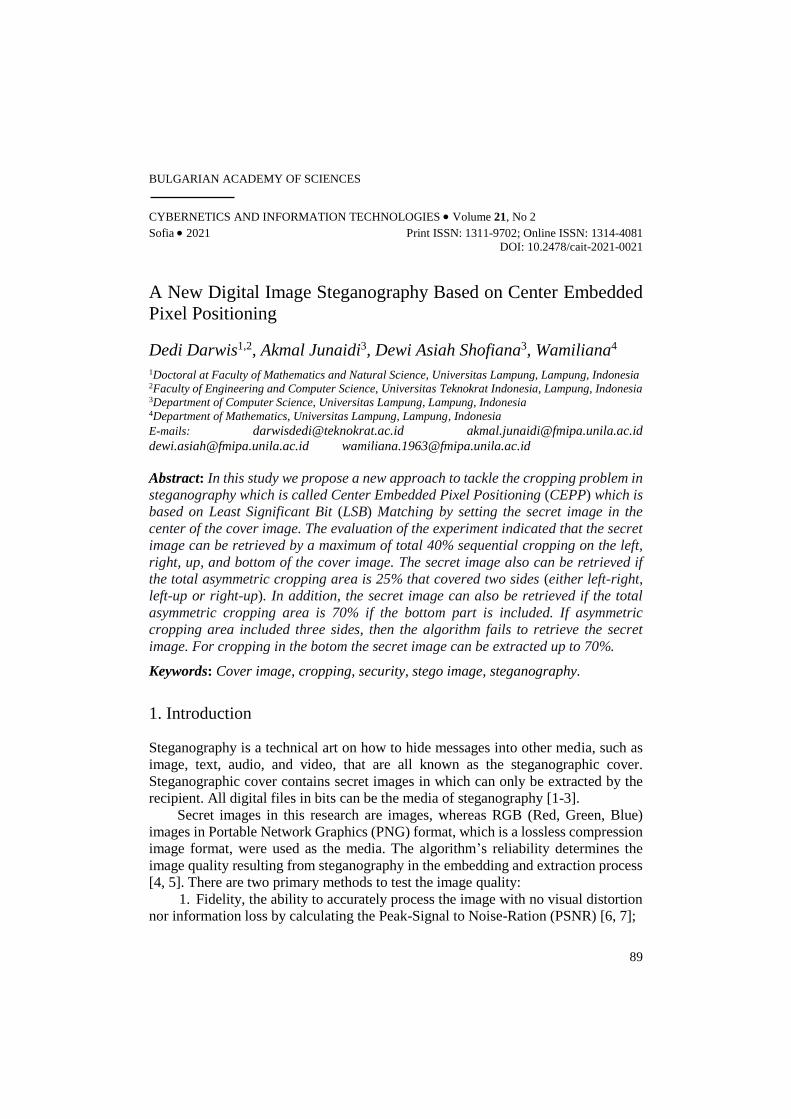
2.1. Message embedding method
PNG image is utilized as the hidden message that will be embedded into the cover
image in the same format. Fig. 1 illustrates the general message insertion process in
the proposed method.
Fig. 1. Message inserting process
The procedure below describes the steps of the embedding/inserting process.
1. Include cover image
In this step, the algorithm scans the number of columns of the cover image. If
the number of columns = a mod (8), then a is the number of shifting needed to put
the initial point (north west corner) of the message container area.
2. Include message image
The size of the secret image must be smaller than the cover image. In this
proposed algorithm, we implement the secret images which size do not exceed 110
pixels. The reason for using 110 pixels is due to the quality of the stego-image. In
this step pixels value is converted to binary and then change the last bit of the image
to be “0” using LSB.
3. Define the message container area
This process is at the heart of the approach to the proposed method. The first
step carried out was to change the pixel value of the message image into a list form,
then validates the width and height of the cover image so that it is divisible by 8.
Afterward, determine the coordinates to insert the message (xs, xe, ys, ye), called the
container, as illustrated in Fig. 2. Calculation on how to determine the container
coordinate is provided in
(1) xs =1
4 𝑤, xe = 𝑤 − xs,
(2) ys =1
4 ℎ, ye = ℎ − ys,
where: xs = Container’s width start point; xe = Container’s width end point;
ys = Container’s height start point; ye = Container’s height end point; 𝑤 = Cover image width; ℎ = Cover image height.

92
Fig. 2. Preparation of container
After obtaining the size of the message container, validation is performed to
ensure that the width of the container is divisible by 8, as in (3) as follows:
(3) xs = xs + (8 − xs mod(8)),
xe = xe + (8 − xe mod(8)).
If the message length is greater or equal to the area of the container, then the
message cannot be embedded. Otherwise, all message bits are embedded in the
specified container, and a stego-image is created.
4. Message inserting process
This process starts by changing the pixel value of the cover image into binary
and then changing all the last bits of the cover image into “1” using LSB. This
changing is needed to discriminate message counter area and other areas. Since the
image is in RGB then this procedure should be done for each channel (Red, Green,
Blue). The process will take longer if the colour of cover image is very diverse.
5. Create a stego-key
Stego-key is used to extract the secret image. In this proposed algorithm, the
stego-key is determined by counting the weight and height of the secret image.
Moreover, the stego-key is also used to validate the size of message container area.
2.2. Message extraction method
Fig. 3. Process of message extraction
93
After the hidden message is successfully embedded in the image, the message will be
sent to the recipient, who extracts the message. Fig. 3 shows the process of message
extraction from a stego-image.
The following steps describe the Message Extraction Process:
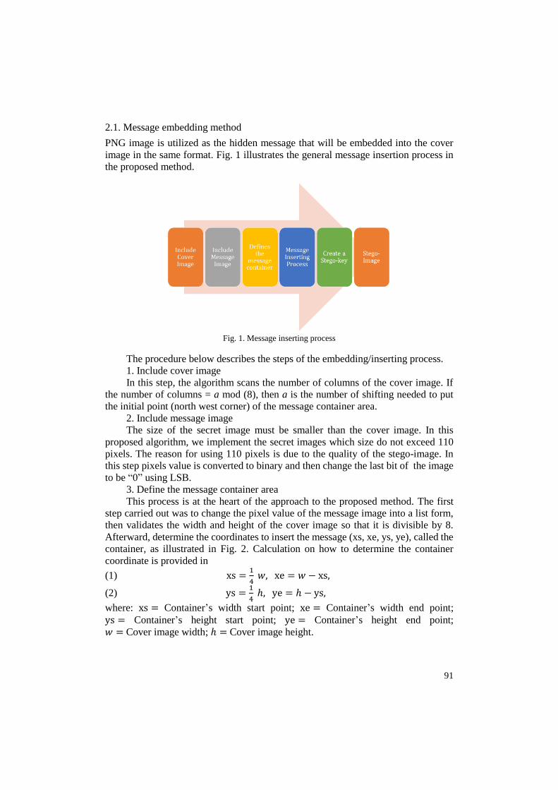
1. Include stego image
Extraction step starts with scanning the stego-image and check whether the
width of the image is divisible by 8 or not. If it is indivisible by 8, the algorithm will
declare two variables: idx and idy, that can determine the starting point to read the
image.
Fig. 4. Length of stego-bit indivisible by 8
Appertaining to Fig. 4, if the stego-image length is indivisible by 8, the
algorithm generates new binary values. The position of the hidden message is at the
center, surrounded by a black border. The next equation is to acquire the idx value
after calculating the image length:
(4) id𝑥 = 𝑤 mod(8),id𝑥 = 21 mod(8),id𝑥 = 5.
Fig. 5. Bit-reading after idx value determination
Fig. 5 shows that the bit reading starts from the 6th bit. Index array in
programming begins from 0; thus idx value of 5 implies that the bit-reading begins
from the 6th bit. By this calculation and bit-reading, stego-image extraction will
conduct successfully on a cropped image.
2. Find the message container area
After scanning the stego-image, stego-key should be validated. The use of stego-
key is to ensure that the extracted message has the same size as the secret image. The
algorithm only scans the area with “1” values, because the area with value “0” are
beyond the message container area.
3. Extracting message images
After finding the message container area and stego-key is validated, the
extraction process will take place to form the original/secret image by changing
binary into pixel.

94
3. Result
3.1. Implementation CEPP Algorithm
The message embedding process is conducted in Python programming language as
shown in Fig. 1. The following is a snippet of source code for processing the cover
image and secret image. cover = cv2.imread(cover, cv2.IMREAD_UNCHANGED)
col, row = cover.shape[:2]
if col % 8 != 0 or row % 8 != 0:
cover = cv2.resize(cover, ((row+(8-row%8)),
(col+(8- col%8))))
col, row = cover.shape[:2]
secret = cv2.imread(secret, cv2.IMREAD_UNCHANGED)
if secret.shape[1] > 110:
secret = cv2.resize(secret, None, fx=0.5, fy=0.5)
blue = []
green = []
red = []
for i in range(secret.shape[0]):
for j in range(secret.shape[1]):
byte_b = secret[i][j][0]
byte_g = secret[i][j][1]
byte_r = secret[i][j][2]
if byte_b == 0:
byte_b = np.array([1], dtype=np.uint8)
if byte_g == 0:
byte_g = np.array([1], dtype=np.uint8)
if byte_r == 0:
byte_r = np.array([1], dtype=np.uint8)
blue.extend(np.unpackbits(byte_b))
green.extend(np.unpackbits(byte_g))
red.extend(np.unpackbits(byte_r))
The secret image is transformed into a list, and then the algorithm calculates the
container coordinates to insert the message into the cover image. Calculating the
container coordinates, cover image validation, and message length towards container
size validation are several processes. The source code used is as follows: xs = int(col*1/4)
xe = col - xs
ys = int(row*1/4)
ye = row - ys
if ys%8 != 0 or ye%8 != 0:
ys = ys + (8-ys%8)
ye = ye + (8-ye%8)

95
3.2. Message embedding algorithm and create a stego-key
The following Source Code, is a snippet of the Embedded Center Positioning
algorithm’s core program, the message embedding process to the container area and
creating the stego-key. idx = 0
for x in range(cover.shape[0]):
for y in range(cover.shape[1]):
bit_b = np.unpackbits(cover[x][y][0])
bit_g = np.unpackbits(cover[x][y][1])
bit_r = np.unpackbits(cover[x][y][2])
if x in range(xs, xe) and y in range(ys, ye):
if idx >= len(blue):
bit_b[7], bit_g[7], bit_r[7] = 0, 0, 0
bit_b = np.packbits(bit_b)
bit_g = np.packbits(bit_g)
bit_r = np.packbits(bit_r)
else:
bit_b[7] = blue[idx]
bit_g[7] = green[idx]
bit_r[7] = red[idx]
bit_b = np.packbits(bit_b)
bit_g = np.packbits(bit_g)
bit_r = np.packbits(bit_r)
if bit_b == 0:
bit_b = bit_b + 1
elif bit_b == 255:
bit_b = bit_b - 1
if bit_g == 0:
bit_g = bit_g + 1
elif bit_g == 255:
bit_g = bit_g - 1
if bit_r == 0:
bit_r = bit_r + 1
elif bit_r == 255:
bit_r = bit_r - 1
idx += 1
else:
bit_b[7], bit_g[7], bit_r[7] = 0, 0, 0
bit_b = np.packbits(bit_b)
bit_g = np.packbits(bit_g)
bit_r = np.packbits(bit_r)
cover[x][y][0] = bit_b
cover[x][y][1] = bit_g
cover[x][y][2] = bit_r
cv2.imwrite(output, cover)
key = (str(secret.shape[0]), str(secret.shape[1]))
print("Stego Key : ", '*'.join(key))

96
3.3. Message extraction algorithm
Before extracting the hidden message from stego-image, the image is read by the
program using the LoadImage Function and DecKey Function to read stego-key
with the following source code: def loadImage(img):
#stego = cv2.imread("cropped.png",
cv2.IMREAD_GRAYSCALE)
stego = cv2.imread(img, cv2.IMREAD_UNCHANGED)
return stego
def decKey(key):
split = key.split('*')
return split
The following is the main source code for the message extraction process: def unhide(img, out, key):
stego = loadImage(img)
k = decKey(key)
col, row = int(k[0]), int(k[1])
idx = 0
idy = 0
if (stego.shape[1] % 8) != 0:
idx = (stego.shape[1] % 8)
idy = 8 - idx
#print(idx, idy)
blue, green, red = core(stego, idx= idx, idy = 0)
#print(len(message))
if len(blue) != col*row:
blue, green, red = core(stego, idx = 0, idy
= idy)
blue = np.array(blue).reshape(col,row)
green = np.array(green).reshape(col,row)
red = np.array(red).reshape(col,row)
else:
blue = np.array(blue).reshape(col,row)
green = np.array(green).reshape(col,row)
red = np.array(red).reshape(col,row)
extract = cv2.merge((blue, green, red))
output = cv2.imwrite(out, extract)
return output
4. Discussion
4.1. embedding message testing
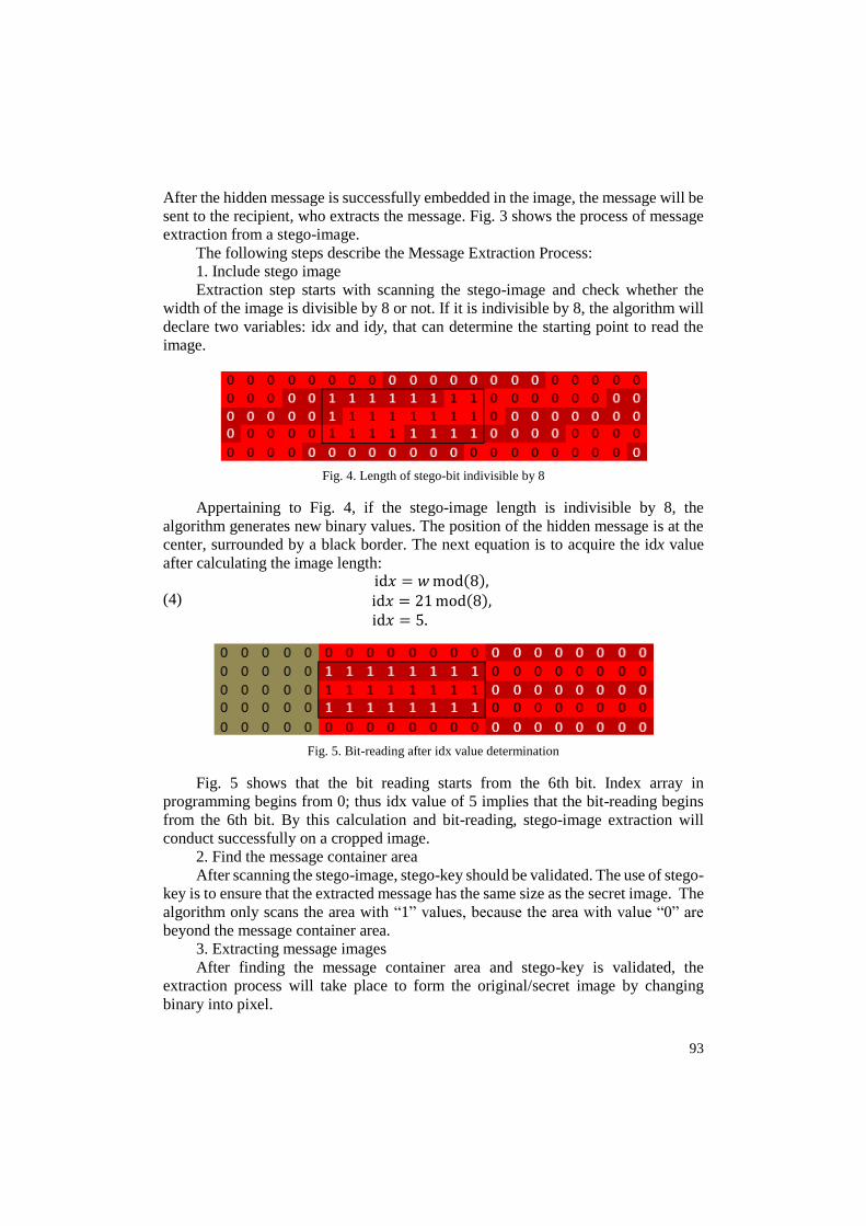
Test results in the embedding process determine the success rate of the program.
Several PNG formatted images are used as cover images, all are RGB as presented
in Fig. 6.
97
Fig. 6. Cover image
Selected cover images must vary in color combination, with some samples they
are considerably dominant in the color of Red, Blue, or Green (RGB). With varying
the color, it will also widen the color spectrum of sample images to analyze the
change in image size and quality between the cover image and the stego-image.
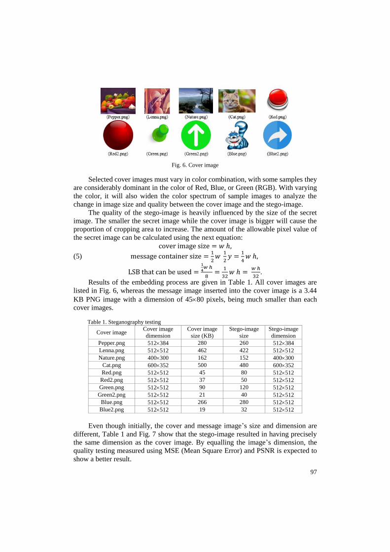
The quality of the stego-image is heavily influenced by the size of the secret
image. The smaller the secret image while the cover image is bigger will cause the
proportion of cropping area to increase. The amount of the allowable pixel value of
the secret image can be calculated using the next equation:
cover image size = 𝑤 ℎ,
(5) message container size =1
2𝑤
1
2𝑦 =
1
4𝑤 ℎ,
LSB that can be used =1
4𝑤 ℎ
8=
1
32𝑤 ℎ =
𝑤 ℎ
32.
Results of the embedding process are given in Table 1. All cover images are
listed in Fig. 6, whereas the message image inserted into the cover image is a 3.44
KB PNG image with a dimension of 4580 pixels, being much smaller than each
cover images.
Table 1. Steganography testing
Cover image Cover image
dimension
Cover image
size (KB)
Stego-image
size
Stego-image
dimension
Pepper.png 512384 280 260 512384
Lenna.png 512512 462 422 512512
Nature.png 400300 162 152 400300
Cat.png 600352 500 480 600352
Red.png 512512 45 80 512512
Red2.png 512512 37 50 512512
Green.png 512512 90 120 512512
Green2.png 512512 21 40 512512
Blue.png 512512 266 280 512512
Blue2.png 512512 19 32 512512
Even though initially, the cover and message image’s size and dimension are
different, Table 1 and Fig. 7 show that the stego-image resulted in having precisely
the same dimension as the cover image. By equalling the image’s dimension, the
quality testing measured using MSE (Mean Square Error) and PSNR is expected to
show a better result.

98
Fig. 7. Visualization of steganography testing
However, the program was unable to maintain image’s size due to the
compression process of the stego-image, converting it into a PNG image format.
Despite its change in size, since the lossless compression method is applied, there is
only a slight effect on the image quality. Based on the size, stego-images generated
from the program are categorized into two: decrement or increment in size. There is
a tendency that images with a wide variety of colors (e.g., cat.png, lenna.png,
nature.png) have a smaller stego-image file size, whereas images having one
dominant color (e.g., red.png, green.png, blue.png) indicate the opposite.
4.2. Extraction message testing
To start the message extraction process, the program will need a stego-key. Stego-
key is responsible for matching the original message image’s size and the size of the
message image in the message container area. The method proposed in this algorithm
is that during the message insertion process, the final bits in the message container
area are assigned to “1”, while in areas outside the container, the bits are assigned to
“0”. For each side of the rectangular area, bits are also assigned to “1” as a boundary.
Determining the boundary area is necessary so that the algorithm can read the
coordinates of the message container area during the message extraction process and
then adjust it to the message’s length and width based on the previously entered stego-
key.
This study applies the LSB matching method, with bits outside the container
boundary being replaced with “0” to simplify the extraction process. In Fig. 8, the
process of reading a message container area is illustrated by marking the message bit
as “1” in the middle area and on each side of the container. In contrast, the remaining
bits outside the container area are marked as “0”. By implementing this method, when
the image is cropped, whether symmetrical or asymmetrical, the messages in the
container area can still be extracted. However, if the cropping reaches the container
area’s boundary, the message will still be corrupted.

99
Fig. 8. Process of reading the message container area
4.3. Imperceptibility test
Imperceptibility testing aims to see how difficult or easy stego-images can be
detected by human vision or the Human Visual System (HVS). This test was carried
out manually by involving 35 respondents who were asked to fill in the questionnaire
by comparing original images (cover images) as well as images with secret images
(stego-images). The questionnaire includes several sample images, as given in
Table 2.
Table 2. Imperceptibility test result
Stego image Different Slightly different No different
Pepper.png 2 2 31
Lenna.png 1 1 33
Nature.png 1 2 32
Cat.png 0 3 32
Red.png 1 3 31
Red2.png 1 2 32
Green.png 2 3 30
Green2.png 1 5 29
Blue.png 0 3 32
Blue2.png 1 3 31
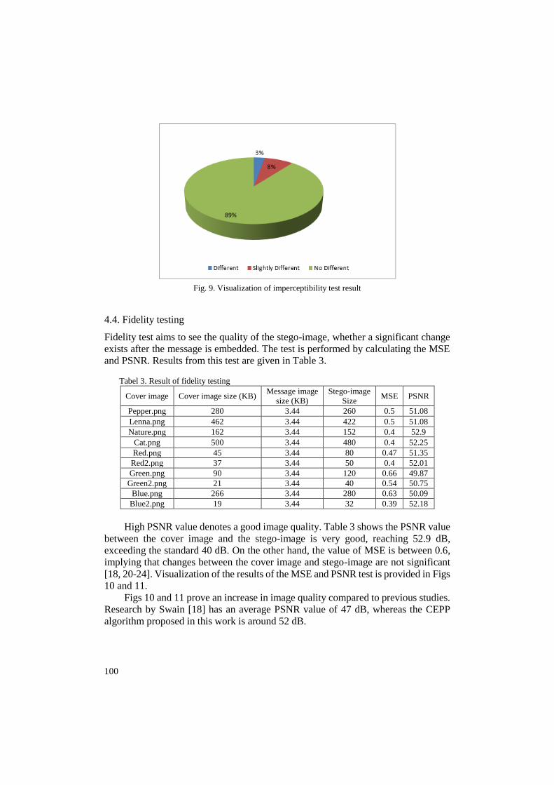
Imperceptibility test includes five image samples, which compares the cover
image and stego image. Based on Table 2 and Fig. 9, around 89% of respondents
stated there is no difference between the cover image and the stego image. It can be
concluded that there is no significant change resulted from the steganography
process.
100
Fig. 9. Visualization of imperceptibility test result
4.4. Fidelity testing
Fidelity test aims to see the quality of the stego-image, whether a significant change
exists after the message is embedded. The test is performed by calculating the MSE
and PSNR. Results from this test are given in Table 3.
Tabel 3. Result of fidelity testing
Cover image Cover image size (KB) Message image
size (KB)
Stego-image
Size MSE PSNR
Pepper.png 280 3.44 260 0.5 51.08
Lenna.png 462 3.44 422 0.5 51.08
Nature.png 162 3.44 152 0.4 52.9
Cat.png 500 3.44 480 0.4 52.25
Red.png 45 3.44 80 0.47 51.35
Red2.png 37 3.44 50 0.4 52.01
Green.png 90 3.44 120 0.66 49.87
Green2.png 21 3.44 40 0.54 50.75
Blue.png 266 3.44 280 0.63 50.09
Blue2.png 19 3.44 32 0.39 52.18
High PSNR value denotes a good image quality. Table 3 shows the PSNR value
between the cover image and the stego-image is very good, reaching 52.9 dB,
exceeding the standard 40 dB. On the other hand, the value of MSE is between 0.6,
implying that changes between the cover image and stego-image are not significant
[18, 20-24]. Visualization of the results of the MSE and PSNR test is provided in Figs
10 and 11.
Figs 10 and 11 prove an increase in image quality compared to previous studies.
Research by Swain [18] has an average PSNR value of 47 dB, whereas the CEPP
algorithm proposed in this work is around 52 dB.

101
Fig. 10. Visualization of MSE result
Fig. 11. Visualization of PSNR result
4.5. Robustness test
A robustness test is conducted to observe whether the stego-image can resist image
processing (specifically cropping) attacks and extract the secret images. In the first
test, we symmetrically crop the stego-image in several directions with the results
presented in Table 4 (✓ is the extraction success; ✕ is the extraction fail).
According to the test results, the stego-image can be cropped symmetrically
from all four directions but with limitations. For the left, right, and upper side, we
can crop the stego-image at a maximum of 25%; otherwise, the message cannot be
extracted. The extraction process will fail due to the embedding process that takes
0.25 of the image’s length or width as the message container area’s boundary, making
the image resistance is only 25% of the overall image. Cropping from the lower side
shows that the message can still be extracted almost 70% from that side (only one
empirical case). In determining the starting point for the message container's
boundary, it does not include the lower side of the image. Therefore, the extraction
process will only fail if we crop the lower side by more than 70 %.
102
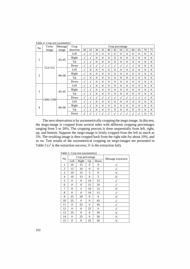
Table 4. Crop test (symmetry)
No Cover
image
Message
image
Crop
direction
Crop percentage
20 25 30 35 40 45 50 55 60 65 70 75
1
512512
4545
Left ✓ ✓ ✕ ✕ ✕ ✕ ✕ ✕ ✕ ✕ ✕ ✕
Right ✓ ✓ ✕ ✕ ✕ ✕ ✕ ✕ ✕ ✕ ✕ ✕
Up ✓ ✓ ✕ ✕ ✕ ✕ ✕ ✕ ✕ ✕ ✕ ✕
Down ✓ ✓ ✓ ✓ ✓ ✓ ✓ ✓ ✓ ✕ ✕ ✕
2 9090
Left ✓ ✕ ✕ ✕ ✕ ✕ ✕ ✕ ✕ ✕ ✕ ✕
Right ✓ ✕ ✕ ✕ ✕ ✕ ✕ ✕ ✕ ✕ ✕ ✕
Up ✓ ✕ ✕ ✕ ✕ ✕ ✕ ✕ ✕ ✕ ✕ ✕
Down ✓ ✓ ✕ ✕ ✕ ✕ ✕ ✕ ✕ ✕ ✕ ✕
3
15001500
4545
Left ✓ ✓ ✕ ✕ ✕ ✕ ✕ ✕ ✕ ✕ ✕ ✕
Right ✓ ✓ ✕ ✕ ✕ ✕ ✕ ✕ ✕ ✕ ✕ ✕
Up ✓ ✓ ✕ ✕ ✕ ✕ ✕ ✕ ✕ ✕ ✕ ✕
Down ✓ ✓ ✓ ✓ ✓ ✓ ✓ ✓ ✓ ✓ ✓ ✕
4 9090
Left ✓ ✓ ✕ ✕ ✕ ✕ ✕ ✕ ✕ ✕ ✕ ✕
Right ✓ ✓ ✕ ✕ ✕ ✕ ✕ ✕ ✕ ✕ ✕ ✕
Up ✓ ✓ ✕ ✕ ✕ ✕ ✕ ✕ ✕ ✕ ✕ ✕
Down ✓ ✓ ✓ ✓ ✓ ✓ ✓ ✓ ✓ ✓ ✕ ✕
The next observation is by asymmetrically cropping the stego-image. In this test,
the stego-image is cropped from several sides with different cropping percentages
ranging from 5 to 50%. The cropping process is done sequentially from left, right,
up, and bottom. Suppose the stego-image is firstly cropped from the left as much as
5%. The resulting image is then cropped back from the right side for about 10%, and
so on. Test results of the asymmetrical cropping on stego-images are presented in
Table 5 (✓ is the extraction success; ✕ is the extraction fail).
Table 5. Crop test (asymmetry)
No Crop percentage
Message extraction Left Right Up Down
1 10 15 0 0 ✓
2 15 10 0 0 ✓
3 10 15 5 0 ✕
4 10 15 0 5 ✕
5 0 0 10 15 ✓
6 0 0 15 10 ✓
7 0 5 10 15 ✕
8 0 0 10 15 ✓
9 25 20 0 0 ✕
10 25 0 0 45 ✓
11 0 25 0 45 ✓
12 0 0 25 0 ✓
13 25 0 0 50 ✕
14 0 25 0 50 ✕
15 0 0 25 50 ✕
103
Asymmetrically cropping the stego-image was carried out 15 times with the
results available in Table 5. Test results show that asymmetrical cropping can be
performed effectively only if the image is cropped on two sides. From Table 5, we
can see that test cases number 1, 2, 5, 6, 8, 10, 11, and 12 are only cropped on two
sides; thus, messages can be extracted successfully. However, when the cropping
attack is performed on more than two sides, such as in test cases number 3, 4, and 7,
the extraction process will fail. The message container are damaged when the third
cropping is conducted on a different side.
Results of observations on test cases number 10, 11, and 12 prove that the
message can still be extracted if the maximum cropping area at the bottom is 45%
and 25% from either left, right, or top. Meanwhile, test cases number 13, 14, and 15
fail to extract since the total cropping areas are greater than 70%.
5. Conclusion
Based on the discussion, the CEPP algorithm shows a remarkable result in image
steganography, proved by its success in the embedding and message extraction
processes. Stego-images generated using the CEPP algorithm are considered very
good, as indicated by the MSE and PSNR values. The images can also be received
through the Human Visual System (HVS), shown by the Imperceptibility Test results.
CEPP algorithm can resist cropping attacks symmetrically from the left, right, and
top of a maximum to 25%, while performing better at the bottom with a resistance
limit of more than 70%. This proposed algorithm can also resist asymmetric cropping
attacks as long as they are only performed on two sides with a total cropping
percentage, not more than 25%. All results are based on empirical data.
Acknowledgments: This research is funded by The Ministry of Research and Technology/The National
Research and Innovation Agency, the Republic of Indonesia under the schema Doctoral Research
Grant 2021.
R e f e r e n c e s
1. D e s o k y, A. Noiseless Steganography. CRC Press, 2012.
2. A b d E l-L a t i f , A. A., B. A b d E l-A t t, S. E. V e n e g a s-A n d r a c a. A Novel Image
Steganography Technique Based on Quantum Substitution Boxes. – Optics and Laser
Technology, Vol. 116, 2019, pp. 92-102.
3. A l-A f a n d y, K. A., O. S. F a r a g a l l a h, A. E l m h a l a w y, E. S. M. E l-R a b a i e, G. M.
E l-B a n b y. High Security Data Hiding Using Image Cropping and LSB Least Significant Bit
Steganography. – In: 4th International Colloquium on Information Science and Technology
(CIST’16), IEEE, 2016, pp. 400-404.
4. K u m a r, V., D. K u m a r. Digital Image Steganography Based on Combination of DCT and DWT.
– Communications in Computer and Information Science, Vol. 101, 2010, pp. 596-601.
5. K u m a r, S. K., P. D. K. R e d d y, G. R a m e s h, V. R. M a d d u m l a. Image Transformation
Technique Using Steganography Methods Using LWT Technique. – International Information
and Engineering Technology Assocation, Vol. 36, 2019, No 3, pp. 233-237.
6. J u a r e z-S a n d o v a l, O., M. C e d i l l o-H e r n a n d e z, G. S a n c h e z-P e r e z, K. T o s c a n o-
M e d i n a, H. P e r e z-M e a n a, M. N a k a n o-M i y a t a k e. Compact Image Steganalysis
for LSB-Matching Steganography. – In: Proc. of 5th International Workshop on Biometrics
and Forensics, IWBF, 2017.

104
7. K a d h i m, I. J., P. P r e m a r a t n e, P. J. V i a l, B. H a l l o r a n. Comprehensive Survey of Image
Steganography: Techniques, Evaluations, and Trends in Future Research. – Neurocomputing,
Vol. 335, 2019, pp. 299-326.
8. M i s h r a, M., P. M i s h r a, M. C. A d h i k a r y. Digital Image Data Hiding Techniques:
A Comparative Study. – Ansvesa, Vol. 7, 2014, No 2, pp. 105-115.
9. M i s h r a, B., R. B e g, V. P. S i n g h. Information Security through Digital Image Steganography
Using Multilevel and Compression Technique. – MIT International Journal of Computer
Science & Information Technology, Vol. 3, 2013, No 1, pp. 26-29.
10. H u, D., L. W a n g, W. J i a n g, S. Z h e n g, B. L i. A Novel Image Steganography Method via Deep
Convolutional Generative Adversarial Networks. – IEEE Transactions on Information
Forensics and Security, Vol. 6, 2018, pp. 38303-38314.
11. S i n g h , S., R. B e g , T. J. S i d d i q u i. Robust Image Steganography Using Complex Wavelet
Transform. – In: Proc. of International Multimedia, Signal Processing and Communication
Technologies, IMPACT, 2013, pp. 56-30.
12. H u s s a i n, M., A. W. A. W a h a b, Y. I. B i n I d r i s, A. T. S. H o, T. S. J u n g. Image
Steganography in Spatial Domain: A Survey. – Signal Processing: Image Communication
Vol. 65, 2018, pp. 46-66.
13. Z h o u, Z., Y. M u, Q. M. J. W u. Coverless Image Steganography Using Partial-Duplicate Image
Retrieval. – Soft Computing, Vol. 23, 2019, No 23, pp. 4927-4938.
14. D a r w i s, D., A. J u n a i d i, W a m i l i a n a. A New Approach of Steganography Using Center
Sequential Technique. – In: Journal of Physics: Conference Series. Vol. 1338. 2019.
15. J u a r e z-S a n d o v a l, O., A. F i e r r o-R a d i l l a, A. E s p e j e l-T r u j i l l o, M. N a k a n o-
M i y a t a k e, H. P e r e z-M e a n a. Cropping and Noise Resilient Steganography Algorithm
Using Secret Image Sharing. – In: Proc. of 6th International Conference on Graphic and Image
Processing (ICGIP’14), Vol. 9443, 2015.
16. A k a r, F., Y. Y a l m a n, H. S. V a r o l. Data Hiding in Digital Images Using a Partial Optimization
Technique Based on the Classical LSB Method. – Turkish Journal of Electrical Engineering
and Computer Sciences, Vol. 21, 2013, pp. 2037-2047.
17. S e t i a d i, D. R. I. M., J. J u m a n t o. An Enhanced LSB-Image Steganography Using the Hybrid
Canny-Sobel Edge Detection. – Cybernetics and Information Technologies, Vol. 18, 2018,
No 2, pp. 74-88.
18. S w a i n, G., S. K. L e n k a. A Novel Steganography Technique by Mapping Words with LSB
Array. – International Journal of Signal and Imaging Systems Engineering, Vol. 8, 2015,
No 1-2, pp. 115-122.
19. A l h u m y a n i, H. Efficient Image Cipher Based on Baker Map in the Discrete Cosine Transform.
– Cybernetics and Information Technologies, Vol. 20, 2020, No 1, pp. 68-81.
20. W a m i l i a n a, M. U s m a n, A. H i j r i a n i, W a r s i t o, R. S e t i a w a n. The Hybrid Methods of
Column Transposition with Adaptive Minimum Error Least Significant Bit Replacement
(AMELSBR) Using File jpg/jpeg and png. – International Journal of Computer Science and
Network Security, Vol. 17, 2017, No 7, pp. 174-179.
21. Z h a n g, Y., C. Q i n, W. Z h a n g, F. L i u, X. L u o. On the Fault-Tolerant Performance for a Class
of Robust Image Steganography. – Signal Processing, Vol. 146, 2018, pp. 99-111.
22. Z h a n g, X., F. P e n g, M. L o n g. Robust Coverless Image Steganography Based on DCT and
LDA Topic Classification. – IEEE Transactions on Multimedia. Vol. 20, 2018, No 12,
pp. 3223-3238.
23. W u, P., Y. Y a n g, X. L i. StegNet: Mega Image Steganography Capacity with Deep Convolutional
Network. – Future Internet, Vol. 10, 2018, pp. 1-15.
24. S a h u, A. K., G. S w a i n, E. S. B a b u. Digital Image Steganography Using Bit Flipping. –
Cybernetics and Information Technologies, Vol. 18, 2018, No 1, pp. 69-80.
Received: 15.12.2020; Second Version: 17.03.2021; Third Version: 13.04.2021;
Accepted: 28.04.2021 (fast track)