a new guidance algorithm for a powered ram air parafoil ... · the-loop simulation (hils) study,...
TRANSCRIPT

International Journal of Applied Engineering Research ISSN 0973-4562 Volume 12, Number 18 (2017) pp. 7558-7565
© Research India Publications. http://www.ripublication.com
7558
A New Guidance Algorithm for a Powered Ram Air Parafoil System under
Wind
Tae-Wook Kim* and Yongkyu Song**
*Graduate student, Ph.D. program, ** Ph.D., Professor Department of Aerospace and Mechanical Engineering, Korea Aerospace University, Goyang City, South Korea.
Orcid ID: 0000-0001-7956-8464 **Corresponding author
Abstract
In this paper a new guidance algorithm for a powered ram air
parafoil under wind is considered. After analyzing 6 DOF and
9 DOF nonlinear dynamic models of the parafoil system, wind
effect is added to them. In order to keep the vehicle on the
desired flight path an effective guidance algorithm using
estimated wind information is proposed. After a Hardware-In-
the-Loop Simulation (HILS) study, flight tests are performed
to evaluate the new guidance algorithm under real wind.
Keywords: Powered Ram-Air Parafoil UAV, HILS
(Hardware In the Loop Simulation), Wind estimation
algorithm, Resultant Vector Guidance
INTRODUCTION
The advantage that a parafoil system can carry greater payload
compared to its weight than fixed-wing or rotary-wing aircraft
makes them useful for bulk air delivery. Because it can now
be GPS-guided to a target the parafoil system can be a good
means for civil uses such as medical or food supplies in
disaster area as well as military uses. However the parafoil
system is very susceptible to wind disturbances, which makes
it difficult to design a good autopilot for it.
Calise and Preston [1] has developed a method for
approximately correcting a guidance command for the effect
of the winds. An analysis shows that the effects of wind on
guidance loop stability are equivalent to increasing the
guidance loop gain under most flight conditions and can even
cause a sign reversal in the loop gain when the wind speed
exceeds the air speed of the vehicle. Luders et al [2] present
an on-line robust trajectory planning to execute collision
avoidance and precision landing under wind uncertainty.
Explicit real-time wind modeling and classification is used to
anticipate future disturbances and a sampling technique
ensures that robustness to possible variation is efficiently
maintained. Other most works [3-6] seek robust parafoil
terminal guidance for accurate and upwind landing under
various wind disturbances.
If a parafoil system can get wind speed and direction the
information would help to develop more capable autopilot.
However, a parafoil system assumes low cost so it is not
typically equipped with inertial systems and air data systems.
Therefore even a rough on-line estimation of wind speed and
direction would help to improve guidance performance for
flight path following. Thus in this work an effective guidance
algorithm using the approximately estimated wind speed and
direction is sought under constant horizontal wind. The
algorithm is flight tested and shows its performance.
MODELING AND HILS
Parafoil Modeling including wind
In order to design an effective guidance and control system
for a parafoil system a proper mathematical model is needed.
Based on Ref. [7] 6 DOF and 9 DOF models for a powered
parafoil system have been implemented via MATLAB
Simulink. While 6 DOF model assumes a rigid body for the
whole parafoil system, 9 DOF model adds the interaction
between canopy and payload to 6 DOF model.
Figures 1 and 2 show some simulation comparisons of 6 DOF
and 9 DOF models, where small discrepancies between
models reflect the angle (and angular rate) differences of
canopy and payload in 9 DOF model. These discrepancies do
not result in a big gap in 3D flight trajectory between two
models as in Figure 2. In this study 6 DOF model seems to
play enough role because GPS-based guidance is sought. Thus
6 DOF model including wind effect is employed in this study.
Figure 1 : Attitude Comparison of 6 DOF and 9 DOF
Modeling
International Journal of Applied Engineering Research ISSN 0973-4562 Volume 12, Number 18 (2017) pp. 7558-7565
© Research India Publications. http://www.ripublication.com
7559
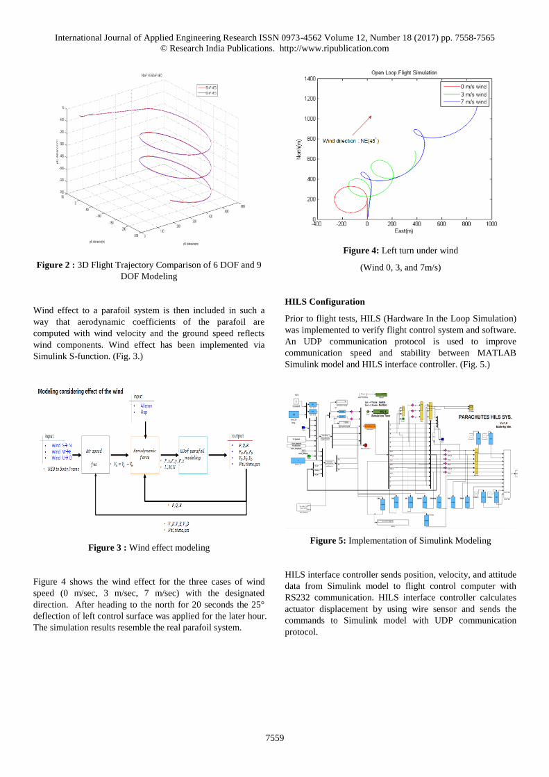
Figure 2 : 3D Flight Trajectory Comparison of 6 DOF and 9
DOF Modeling
Wind effect to a parafoil system is then included in such a
way that aerodynamic coefficients of the parafoil are
computed with wind velocity and the ground speed reflects
wind components. Wind effect has been implemented via
Simulink S-function. (Fig. 3.)
Figure 3 : Wind effect modeling
Figure 4 shows the wind effect for the three cases of wind
speed (0 m/sec, 3 m/sec, 7 m/sec) with the designated
direction. After heading to the north for 20 seconds the 25°
deflection of left control surface was applied for the later hour.
The simulation results resemble the real parafoil system.
Figure 4: Left turn under wind
(Wind 0, 3, and 7m/s)
HILS Configuration
Prior to flight tests, HILS (Hardware In the Loop Simulation)
was implemented to verify flight control system and software.
An UDP communication protocol is used to improve
communication speed and stability between MATLAB
Simulink model and HILS interface controller. (Fig. 5.)
Figure 5: Implementation of Simulink Modeling
HILS interface controller sends position, velocity, and attitude
data from Simulink model to flight control computer with
RS232 communication. HILS interface controller calculates
actuator displacement by using wire sensor and sends the
commands to Simulink model with UDP communication
protocol.
International Journal of Applied Engineering Research ISSN 0973-4562 Volume 12, Number 18 (2017) pp. 7558-7565
© Research India Publications. http://www.ripublication.com
7560
Figure 6: Implementation of HILS
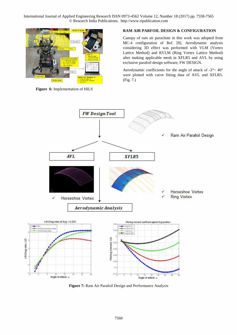
RAM AIR PARFOIL DESIGN & CONFIGURATION
Canopy of ram air parachute in this work was adopted from
MC-4 configuration of Ref. [8]. Aerodynamic analysis
considering 3D effect was performed with VLM (Vortex
Lattice Method) and RVLM (Ring Vortex Lattice Method)
after making applicable mesh in XFLR5 and AVL by using
exclusive parafoil design software, FW DESIGN.
Aerodynamic coefficients for the angle of attack of -3°~ 40°
were plotted with curve fitting data of AVL and XFLR5.
(Fig. 7.)
Figure 7: Ram Air Parafoil Design and Performance Analysis

International Journal of Applied Engineering Research ISSN 0973-4562 Volume 12, Number 18 (2017) pp. 7558-7565
© Research India Publications. http://www.ripublication.com
7561
It is shown that Lift-Drag ratio is approximately 3 to 1 in
aerodynamic analysis of modified MC-4 canopy. For the
thrust, one 5.3KW BLDC motor with 2 blades was adopted
showing maximum thrust of 14kgf with 24 V, 20 A battery. It
is expected from the thrust test result that under the condition
of level flight with 60% thrust, battery supplies a 15 minute-
flight (Fig. 8.). Figure 9 shows the current consumption,
voltage condition, and thrust according to motor driver input
command.
To control brake line, arm type or winch type actuator is used.
Arm type has fast response but poor torque and bigger size
compared to winch type. With this reason winch type actuator
was adopted in this work.
Figure 8: Thrust test system configuration
Figure 9: Thrust system performance analysis
Table 1: Comparison of actuator drive system
Arm type Winch type
The table below shows configuration of powered ram air
parafoil.
Table 2 : Ram Air Parafoil Specifications
Specifications Ram Air Parafoil
Canopy
Model Modified MC-4
Chord(m) 1.27
Span(m) 3.22
Aspect Ratio 2.54
Inlet height(m) 0.153
Airframe
Power 5.3KW BLDC
Weight 1.2 Kgf
Actuator Type Winch Type
A NEW GUIDANCE ALGORITHM USING WIND
INFORMATION
The basic guidance algorithm to keep an aircraft on the track
between two way points is to reduce the cross track error, d, to
zero while flying to next waypoint. (Fig. 10.)

International Journal of Applied Engineering Research ISSN 0973-4562 Volume 12, Number 18 (2017) pp. 7558-7565
© Research India Publications. http://www.ripublication.com
7562
Figure 10: Basic cross-track guidance
However, flight with cross track guidance algorithm without
considering wind effect will sideslip under wind as shown in
HILS (Fig. 11.). Real flight test results also show the similar
tendency as seen in Fig. 12.
In order to effectively reduce the cross-track error even under
wind this paper proposes a new guidance algorithm using
wind direction and speed information estimated by the scheme
of Ref. [9] (Fig. 13.). The algorithm estimates wind speed and
direction with only GPS measurements, and thus the relative
speed of the parafoil system to the air mass, which is equal to
the ground speed in case of no wind. The wind speed and
direction is roughly estimated once the vehicle flies more than
half circle and is assumed constant for the maneuver.
It is assumed that the relative speed to the air mass of the
parafoil system keeps constant. That is, the throttle for thrust
is fixed because the throttle change brings the altitude change
as well as the speed change, which is not desirable in the
waypoint navigation at a constant altitude. Only the heading
control using left or right flap is assumed.
Figure 11: HILS simulation results with cross-track guidance
Figure 12: Flight test trajectory with basic cross-track
guidance
Figure 13: Wind estimation algorithm
A new guidance algorithm exploiting wind information is to
make the normal component of the total ground speed to flight
path the same whether there is a wind or not (Fig. 14.).
That is, suppose that Vnet0 is the desired velocity vector
calculated by the cross-track error guidance when there is no
wind. This vector gives then the vehicle the normal
component Vnet_cross to the flight path. Our goal is to keep the
normal component of the ground speed the same even if there
is a wind velocity Vwind. To do this the heading of the parafoil
velocity vector must be rotated from (x0, y0) to(x̅, y̅). Then
the resultant vector of Vnet and Vwind becomesVtotal , which
gives the same normal component as Vnet_cross. The heading
International Journal of Applied Engineering Research ISSN 0973-4562 Volume 12, Number 18 (2017) pp. 7558-7565
© Research India Publications. http://www.ripublication.com
7563
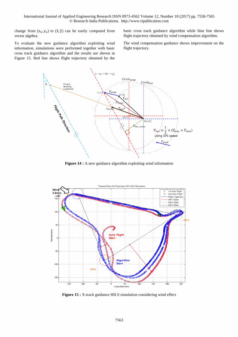
change from (x0, y0) to (x̅, y̅) can be easily computed from
vector algebra.
To evaluate the new guidance algorithm exploiting wind
information, simulations were performed together with basic
cross track guidance algorithm and the results are shown in
Figure 15. Red line shows flight trajectory obtained by the
basic cross track guidance algorithm while blue line shows
flight trajectory obtained by wind compensation algorithm.
The wind compensation guidance shows improvement on the
flight trajectory.
Figure 14 : A new guidance algorithm exploiting wind information
Figure 15 : X-track guidance HILS simulation considering wind effect

International Journal of Applied Engineering Research ISSN 0973-4562 Volume 12, Number 18 (2017) pp. 7558-7565
© Research India Publications. http://www.ripublication.com
7564
FLIGHT TEST AND ANALYSIS
Flight tests were also performed to evaluate the new wind
compensation guidance algorithm. During the test wind speed
observed was 7 ~ 8 m/sec and mean wind direction was -61.2°
while there was also some gust.
The flight test was performed in one sortie, where the basic
cross-track guidance was first applied and then consecutively
new wind compensation algorithm was applied. During the
first flight (red line) wind direction and speed was also
estimated by the scheme of Kim and Song (2015) using GPS
data. Then the estimated wind direction and speed were used
to generate the new heading command for the wind
compensation guidance algorithm (blue line).
Figure 16 shows the picture of the powered ram air parafoil
and Figure 17 shows flight trajectories. While the red line
shows large deviations from the flight path line due to strong
wind, the blue line (wind compensation guidance algorithm)
shows considerable improvement in the flight path keeping.
Figure 16 : Powered Ram Air Parafoil Test Flight
Figure 17: Powered Ram Air Parafoil Autonomous Flight
trajectory
CONCLUSION
This paper presents a new wind compensation guidance
algorithm for a powered ram air parafoil system and flight
tests were performed to evaluate the algorithm. A 6 DOF
model together with wind effect is used for the simulation.
To compensate for wind effect, wind speed and direction
estimates were used in the guidance to keep the normal
component of the ground speed the same whether there is a
wind or not. The new algorithm shows considerable
improvement under real wind.
ACKNOWLEDGEMENT
This research was supported by the MSIT (Ministry of
Science and ICT), Korea, under the ITRC(Information
Technology Research Center) support program,(IITP-2017-
2014-0-00678) supervised by the IITP(Institute for
Information & communications Technology Promotion)
REFERENCES
[1] Calise, A. J. and Preston, D., “Approximate Correction
of Guidance Commands for Winds”, AIAA Paper No.
2009-2997, Proc. 20th AIAA Aerodynamic Decelerator
Systems Technology Conference and Seminar, Seattle,
Washington, 2009.
[2] Luders, B, Sugel, I., How, J. P., "Robust Trajectory
Planning for Autonomous Parafoils under Wind
Uncertainty", AIAA Infotech@Aerospace Conference,
Boston, 2013.
[3] Rogers, J., and Slegers, N., “Robust Parafoil Terminal
Guidance Using Massively Parallel Processing,” Proc.
AIAA Atmospheric Flight Mechanics Conference,
Minneapolis, Minnesota, 2012.
[4] Van der kolf, G., “Flight Control System for an
Autonomous Parafoil”, Master’s thesis, Stellenbosch
University, 2013.
[5] Ward, M., “Adaptive Glide Slope Control for Parafoil
and Payload Aircraft”, Master’s thesis, Georgia
Institute of Technology, 2012.
[6] Toolhey, D., “Development of a Small Parafoil Vehicle
for Precision Delivery, Master’s thesis, Massachusetts
Institute of Technology, 2005
[7] Slegers, N., “Effects of Canopy-Payload Relative
Motion on Control of Autonomous Parafoils,” Journal
of Guidance, Control, and Dynamics, Vol 33, No 1,
2010, pp 116-125.
[8] Eslambolchi, A., and Johari, H., "Simulation of Flow
field Around a Ram-Air Personnel Parachute Canopy",
Journal of Aircraft, Vol. 50, No. 5, 2013, pp. 1628-
1636.

International Journal of Applied Engineering Research ISSN 0973-4562 Volume 12, Number 18 (2017) pp. 7558-7565
© Research India Publications. http://www.ripublication.com
7565
[9] Kim, T., and Song, Y., “A Study on the Wind
Estimation for Unmanned Parafoil System” Journal of
the korean society for aviation and aeronautics , Vol.23,
no.1, 2015, pp.8-13
[10] Benton, J. E., “Miniaturization, Integration, Flight
Testing, and Performance Analysis of a Scalable
Autonomous GPS-Guided Parafoil System for Targeted
Payload Return”, Master’s thesis, San jose State
University, 2012.
[11] Umenberger, J., “Guidance, Navigation and Control of
a Small-Scale Paramotor”, Australasian Conference on
Robotics and Automation, University of Sydney , 2012.
[12] Watanabe, M., and Ochi, Y., “Modeling and
Simulation of Nonlinear Dynamics of a Powered
Paraglider”, Proc. AIAA Guidance, Navigation and
Control Conference and Exhibit , 2008.