a new hybrid meshless-differential order reduction (hm-dor)
TRANSCRIPT
8/2/2019 A New Hybrid Meshless-differential Order Reduction (hM-DOR)
http://slidepdf.com/reader/full/a-new-hybrid-meshless-differential-order-reduction-hm-dor 1/14
Engineering Structures 25 (2003) 141–154
www.elsevier.com/locate/engstruct
A new hybrid meshless-differential order reduction (hM-DOR)method with applications to shape control of smart structures via
distributed sensors/actuators
T.Y. Ng ∗, Hua Li, J.Q. Cheng, K.Y. Lam
Institute of High Performance Computing, National University of Singapore, 89C Science Park Drive, #02-11/12, The Rutherford, Singapore
Science Park 1, Singapore 118261
Received 17 October 2001; received in revised form 14 June 2002; accepted 20 July 2002
Abstract
This paper presents the development of a new hybrid numerical method, the hM-DOR method, which is based on an order-reduction technique for partial differential equations, and combines the true-meshless collocation technique with a fixed reproducingkernel approximation. The proposed method is able to directly impose overlapping boundary conditions, a procedure difficult toaccomplish with existing collocation-based meshless methods. The present method is applied to examine thin-plate bending forplates of various geometries and different boundary conditions. Its efficiency and accuracy are validated by numerical comparisonswith finite element results. Furthermore, it is also used to simulate the deformation shape control of the uniformly loaded smartbeams and plates integrated with piezoelectric sensors/actuators. The numerical results here again verify the efficiency of this newlydeveloped method.
2002 Elsevier Science Ltd. All rights reserved.
Keywords: Meshless method; Point collocation; Reproducing kernel; Order reduction; Smart structure; Shape control
1. Introduction
Numerical approaches in computational mechanicshave been developed on a continual basis ever since theFEM proved effective for a wide range of engineeringapplications. Over the last few years, the meshlessapproach, often referred to as the next-generationnumerical tool, has attracted much attention amongstresearchers world-wide [1]. In general, meshlessmethods can be classified roughly into two groups,namely, those that require a background mesh such asGalerkin-based techniques [2–16] and those that do notrequire a background mesh such as collocation tech-niques [17–20]. The latter collocation-based techniquesare true meshless methods, and include the finite cloudmethod [21], which combines collocation technique withthe fixed reproducing kernel approximation. One of itsadvantages is that both Dirichlet and Neumann boundaryconditions may be implemented exactly, but this is pro-
∗ Corresponding author.
0141-0296/03/$ - see front matter 2002 Elsevier Science Ltd. All rights reserved.
doi:10.1016/S0141-0296(02)00116-5
vided there are no two boundary conditions, involvingthe same variable, which need to be satisfied concur-rently at a boundary point. This leads us to one of itsdrawbacks, i.e., since only one boundary conditioninvolving one variable can be enforced at each scatteredpoint along the edge, it is difficult to implement the over-lapping boundary conditions, where there are more thanone boundary condition involving the same variable,describing the edge condition. An example of overlap-ping boundary conditions is the bending problem of asimply-supported plate which includes both the essentialzero-displacement and natural zero-moment boundaryconditions.
In order to overcome the difficulty of implementingthe overlapping boundary conditions, we develop here anew hybrid meshless-differential order reductionmethod, which we call the hM-DOR method. Thismethod combines the true-meshless finite cloud methodwith an order-reduction technique for partial differentialequations (PDE) for full exploitation of the merits of collocation methods and the direct imposition of theoverlapping boundary conditions. A simple and efficient

8/2/2019 A New Hybrid Meshless-differential Order Reduction (hM-DOR)
http://slidepdf.com/reader/full/a-new-hybrid-meshless-differential-order-reduction-hm-dor 2/14
142 T.Y. Ng et al. / Engineering Structures 25 (2003) 141–154
technique validated for the solution of high-order PDEs
with overlapping boundary-value characteristics, the
present hM-DOR method first introduces selected vari-
ables suitable for the reduction of the higher-order PDEs
into the lower-order PDEs. This is followed by recon-struction of the governing PDEs and given boundary
conditions to correspond to the selected variables. Then,for the scattered set of points in the computational
domain, the collocation technique with fixed reproducing
kernel approximation, is imposed on the order-reduced
PDEs and restructured boundary conditions for discretiz-
ation of the boundary-value problem. Finally, the
numerical results are obtained by solving the set of com-
plete linear discrete algebraic equations for point values.
For verification of the convergence characteristics and
accuracy of the developed hM-DOR method, numericalcomparisons with established results are made for the
plate-bending problem, in which various geometric
shapes and different boundary conditions were con-
sidered. Further, the present true-meshless hM-DOR
method will be applied to smart structures, where defor-
mation shape control of one-dimensional beam and two-
dimensional plate structures integrated with arbitrarily
distributed piezoelectric sensors/actuators are simulated
to optimize both the dimension and location of the actu-ators in an active control systems.
2. hM-DOR method—a true meshless method
The presently developed hM-DOR method exploits
the order-reduction technique for PDEs and the collo-cation technique with fixed reproducing kernel approxi-mation, to solve boundary-value problems with overlap-
ping boundary conditions.
2.1. Fixed reproducing kernel approximation
The fixed reproducing kernel approximation is based
on the classical reproducing kernel particle method
(RKPM) [4]. It defines the approximate solution of an
unknown real function f ( x, y) as
f ̃ ( x, y) C ( x, y,u,v)K ( xk u, yk v) f (u,v)dudv (1)
where K ( xk u, yk v) is the kernel function and the point
( xk , yk )is the center point of kernel. C ( x, y,u,v) is a correc-
tion function and is defined as
C ( x, y,u,v) B(u,v)C∗( x, y) (2)
where C∗T ( x, y) {c1,c2,%,cm} is an unknown mth-
order column coef ficient vector of the correction func-
tion. B(u,v) {b1(u,v),b2(u,v),%,bm(u,v)} is a mth-order
row vector of basis functions and its definition usually
depends on the different boundary-value problems. For
example, in the present two-dimensional plate bending
problem with the overlapping boundary conditions, we
introduce the cubature serendipity-based interpolation
polynomial as the basis functions, namely, when taking
m 8, we have
B(u,v)
{b1(u,v),b2(u,v),…,b
m
(u,v)} (3) {1,u,v,u2,uv,v2,u2v,uv2}
Similarly, depending again on the different boundary-value problems, the fixed kernel function K ( xk u, yk
v) may be constructed by different forms of windowfunctions. In this paper, we use a cubic spline function
to construct the fixed kernel function
K ( xk u, yk v) W ∗(( xk u) / x)W ∗(( yk (4)
v) / y) / ( x y)
in which the cubic-spline form of the window function
W ∗
( z) is given as
W ∗( z) 0 | z|2
(2| z|)3 / 6 1| z|2
(2/3) z2(10.5| z|) | z|1
(5)
where z ( xk u) / x or z ( yk v) / y. x and y
denote the cloud size in the x-direction and y-direction
and they need be adjusted according to the point coordi-
nates and accuracy requirement due to the consistency
conditions of the reproducing kernel approach.The coef ficient vector of the correction function
C ∗T ( x, y) {c1,c2,%,cm} in Eq. (2) is unknown and
determined by satisfying the following consistency con-
ditions
bi( x, y)
C ( x, y,u,v)K ( xk u, yk v)bi(u,v)dudv (6)
i 1,2,…,m
and by substitution of Eq. (2) into Eq. (6) above and
then discretizing the resulting equations, we obtain
bi( x, y)
N T
n 1
B(un,vn)C∗( x, y)K ( xk un, yk (7)
vn)bi(un,vn)sn i 1,2,%m
where N T is the total number of points covering the
interior computational domain and edges and sn is
defined as the surface area of the point n.
Eq. (7) is actually a set of linear algebraic equations
with respect to the coef ficient vector C∗T ( x, y)
{c1,c2,%,cm} and can be rewritten simply into the fol-
lowing matrix form

8/2/2019 A New Hybrid Meshless-differential Order Reduction (hM-DOR)
http://slidepdf.com/reader/full/a-new-hybrid-meshless-differential-order-reduction-hm-dor 3/14
143T.Y. Ng et al. / Engineering Structures 25 (2003) 141 –154
A( xk , yk )C∗( x, y) BT ( x, y) (8)
in which A( xk , yk ) is a symmetric constant matrix related
to the center point ( xk , yk )
Aij( xk , yk )
N T
n 1
bi(un,vn)K ( xk un, yk (9)
vn)b j(un,vn)sn i, j 1,2,%,m
and the unknown coef ficient vector C∗T ( x, y)
{c1,c2,%,cm} can be obtained through some rearrange-
ment of Eq. (8)
C∗( x, y) A1( xk , yk )BT ( x, y) (10)
Substituting Eqs. (2) and (10) into Eq. (1), the
approximate solution of the unknown real function f ( x, y) in Eq. (1) is obtained as
f ˜ ( x, y) B(u,v)A
1
( xk , yk )BT
( x, y)K ( xk u, yk (11)
v) f (u,v)dudv
and in the discretized form
f ̃ ( x, y)
N T
n 1
N n( x, y) f n (12)
where f n is a unknown point value for the point n and
N n( x, y) is defined as the shape function by
N n( x, y) B(un,vn)A1( xk , yk )BT ( x, y)K ( xk un, yk (13)
vn)sn
which is the interpolation function based on the fixed-
kernel window function. It should be noted that the
present shape functions, Eq. (13), are simply the poly-
nomial with respect to x and y, such that any of thederivatives can be obtained directly by the differentiation
of the basic function. Further, it is also validated that
the present shape functions satisfy the consistency con-
ditions.
The above approximation approach with the collo-
cation and fixed reproducing kernel techniques can be
used to solve generic engineering boundary-value prob-
lems. For example,
L f ( x, y) P( x, y)
PDEs in computational domain (14)
f ( x, y) Q( x, y)
Dirichlet boundary condition on D(15)
∂ f ( x, y) / ∂n R( x, y)
Neumann boundary condition on N(16)
where L is a differential operator and f ( x, y) an unknown
real function. By using the point collocation technique
and taking f ̃ ( x, y) as the approximation of f ( x, y), the
discretized approximation forms of the boundary-value
problem are given as
L f ̃ ( xn, yn) P( xn, yn) n 1,2,…, N (17)
f ̃ ( xn, yn) Q( xn, yn) n 1,2,… N D (18)
∂ f ̃ ( xn, yn)
∂n R( xn, yn) n 1,2,… N N (19)
where N , N D and N N are the number of scattered points
in the interior computational domain and along the
Dirichlet and Neumann edges, respectively, and the total
number of scattered points is thus N T ( N
N D N N ).
Substituting the fixed reproducing kernel approxi-
mation of Eq. (12) into the boundary-value problem of Eqs. (17–19) and then rewriting the resulting equation
with respect to the unknown point value f i into matrixform, we have
[ M ij] N T× N T{ f i} N T×1 {d i} N T×1 (20)
where [ M ij] is a N T × N T coef ficient matrix and {d i} N T-
order column coef ficient vector. They are given as
M ij L N j( xi, yi), d i P( xi, yi) (21)
i 1,2,…, N and j 1,2,…, N T
M ij N j( xi, yi), d i Q( xi, yi), i ( N 1),( N (22)
2),…,( N N D) and j 1,2,…, N T
M ij ∂ N j( xi, yi)
∂n, d i R( xi, yi), i ( N N D (23)
1),…,( N N D N N) and j 1,2,…, N T
Solving numerically the set of completed linear
algebraic equations, Eq. (20), the N T-order point-value
vector { f i} is obtained and then the approximation
f ̃ ( x, y) of the boundary-value problem is computedthrough Eq. (12).
Numerical comparisons have shown that the present
meshless approach is suf ficiently accurate and cost
ef ficient. However, there are constrained drawbacks for
its engineering application. For example, it is required
that the intersection between different boundary con-ditions, such as the present Dirichlet and Neumann
boundary conditions, must result in an empty set whena complete solution system is developed by the point
collocation technique. This results in dif ficulty when
applied directly to the partial differential boundary-value
problems with overlapping boundary conditions. In order
to overcome this dif ficulty, the following order-reduction
technique is employed to solve the higher-order PDEs.
8/2/2019 A New Hybrid Meshless-differential Order Reduction (hM-DOR)
http://slidepdf.com/reader/full/a-new-hybrid-meshless-differential-order-reduction-hm-dor 4/14
144 T.Y. Ng et al. / Engineering Structures 25 (2003) 141 –154
2.2. Order-reduction technique for partial differential
equations
In general, overlapping boundary conditions, where
there are more than one boundary condition involvingthe same variable imposed at an edge, are very generic
in engineering applications, especially in the area of computational mechanics. For example, a simply-sup-
ported plate requires both the essential boundary con-
ditions (zero displacement) and natural boundary con-
ditions (zero moment) to be met, and both these
boundary conditions involve the same transverse deflec-
tion variable w. However, current meshless approaches
usually require an empty intersection set between two
adjacent boundary conditions. For example, the popular
Galerkin-based meshless methods simply use two setsof functions to formulate a variational form constructed
by various techniques including the penalty and Lag-
range multiplier methods. One set consists of trial func-
tions and the other consists of test functions [11],
{ f ( x, y)| f ( x, y) H 1, (24)
f ( x, y) Q( x, y) on Essential} (trial functions)
{g( x, y)|g( x, y) H 1, (25)
g( x, y) 0 on Essential} (test functions)
and the domain boundary is defined by the following
EssentialNatural (boundary condition) (26)
EssentialNatural f (empty set) (27)
whereEssential is the essential boundary and
Natural thenatural boundary. Q( x, y) is the given essential boundary
condition. The similar empty-set is also required for the
collocation-based meshless methods. In other words, it
is dif ficult to employ directly the present true-meshless
point collocation technique with fixed reproducing ker-nel approximation for solution of PDEs with the overlap-
ping boundary conditions as
{w( x, y)|w( x, y) H 3,
hE(w) h̄ E(w) and (28)
hN(w) h̄ N(w) on EssentialNatural}
(non empty set)
where h̄ E(w) and h̄ N(w) are essential and natural bound-
ary conditions respectively. The present boundary con-
ditions are the overlapping, i.e., EssentialNatural
Essential Natural, or EssentialNatural f is a non-
empty set.To overcome this drawback, suitable variables
F ( x, y) are selected and introduced not only to reduce the
higher-order PDEs into lower-order PDEs, but also to
separate the overlapping boundary conditions respect-
ively for the introduced variable F ( x, y) and problem vari-
able w( x, y), such that they correspond to empty sets
{w( x, y)|w( x, y) H 3 and
F ( x, y)|F ( x, y) H 3,
hE(w,F ) h̄ E(w,F ) and
hN(w,F ) h̄ N(w,F ) on EssentialNatural}
(29)
After the reconstruction of both the governing PDEsand given boundary conditions to correspond to the two
variables F ( x, y) and w( x, y), a complete reduced partial
differential boundary-value system is developed. Then,
by scattering a set of points in the computational domainand using the collocation technique with fixed reproduc-
ing kernel approximation, the system is discretized to a
set of completed linear algebraic equations. Finally, the
approximate solutions are obtained by numerically solv-
ing the set of algebraic equations.Thus far we have described the presently developed
true-meshless hM-DOR method, which is based on the
order-reduction technique for partial differential equa-
tions and combines the point collocation technique withfixed reproducing kernel approximation. The two sub-
sequent sections will examine the accuracy of the hM-DOR method and study the computational stability of
the methodology for certain engineering applications.
3. Numerical validation of the hM-DOR method
In this section, the accuracy and convergence charac-
teristics of the developed hM-DOR method are examined
numerically for the bending problem in classical thin
plates. Following a brief presentation of the formulationof the hM-DOR method for thin plates with different
overlapping boundary conditions, numerical compari-
sons are made with either exact solutions or FEM results
obtained by the commercial solver MSC/NASTRAN, for
plates of various geometric shapes (including square, tri-
angular and trapezium) and different boundary con-
ditions.
3.1. hM-DOR formulation for classical thin plates
The governing equation of an isotropic plate subjected
to a static transverse load is written classically in termsof the transverse deflection w w( x, y) as follows
D0(∂4w
∂ x4 2
∂4w
∂ x2∂ y2
∂4w
∂ y4) q( x, y) (30)
where D0 is the bending stiffness of the plate and
q( x, y) the distributed load in the transverse z-direction.
The boundary conditions we will consider in this study
include simply-supported boundary conditions
w 0, M n 0 (31)
and free boundary conditions
8/2/2019 A New Hybrid Meshless-differential Order Reduction (hM-DOR)
http://slidepdf.com/reader/full/a-new-hybrid-meshless-differential-order-reduction-hm-dor 5/14
145T.Y. Ng et al. / Engineering Structures 25 (2003) 141 –154
M n 0,V n Qn∂ M ns
∂s 0 (32)
where the subscripts n and s denote the normal and tan-
gential directions at the local edge. The moments andshear forces are usually given in the local edge n–s coor-
dinate system as [22] M n M xcos2 b M ysin2 b2 M xysin bcos b (33)
M ns M xy(cos2 bsin2 b) ( M x M y)sin bcos b (34)
Qn Q xcos b Q ysin b (35)
with b being the angle between the vector n and the axis x of the global x – y coordinate system and
M x D0(∂2w
∂ x2 m
∂2w
∂ y2),
M y D0(∂2w
∂ y2 m
∂2w
∂ x2), (36)
M xy D0(1 m)∂2w
∂ x∂ y
Q x D0∂
∂ x2w,Q y D0
∂
∂ y2w (37)
The boundary conditions, Eqs. (31) and (32), of theplate are overlapping boundary conditions, where there
are two boundary conditions, involving the variable w,
required to be imposed on each edge. These include both
essential boundary conditions w 0 on Essential and
natural boundary conditions M n
0 or V n
0 (both of which are functions of w) on Natural. As described above,
it is very dif ficult to impose directly the overlapping
boundary conditions by the point collocation technique.
By the present hM-DOR method however, the problemcan be solved by introducing a new variable F ( x, y) to
reduce the order of the governing PDE equation, as wellas to separate the overlapping boundary conditions
respectively for the introduced variable F ( x, y) and
deflection variable w( x, y). The introduced variableF ( x, y) here is selected as
F ( x, y) ∂2w
∂ x2
∂2w
∂ y2
in the interior computational domain(38)
and the governing equation, Eq. (30), and the boundaryconditions, Eqs. (31) and (32), can be rewritten as
D0(∂2F
∂ x2
∂2F
∂ y2) q( x, y)
in the interior computational domain
(39)
w 0, F ( x, y)(1 m)∂2w
∂ y2 0
when simply supported edges at x constant
(40)
F ( x, y)(1 m)∂2w
∂ x2 0,
∂F
∂ y (1 m)
∂3w
∂ x2∂ y 0
when free edges at y constant
(41)
In this way, the original boundary-value problem
expressed by Eqs. (30)–(32) are replaced by the reduced
partial differential boundary-value problem expressed byEq. (38)–(41). By the point collocation technique with
fixed reproducing kernel approximation, the approximate
solutions of the transverse deflection and introduced
variable are constructed as
w̃ ( xi, yi)
N T
n 1
N n( xi, yi)wn i 1,2,…, N T (42)
F ˜ ( xi, yi)
N T
n 1
N n( xi, yi)F n i 1,2,…, N T (43)
and the reduced PDEs and boundary conditions arediscretized as:
(1) interior of computational domain
D0(
N T
n 1
N n, xx( xi, yi)F n
N T
n 1
N n, yy( xi, yi)F n) (44)
q( xi, yi) i 1,2,…, N
N T
n 1
N n( xi, yi)F n
N T
n 1
N n, xx( xi, yi)wn (45)
N T
n 1 N n, yy( xi, yi)wn i 1,2,…, N
(2) simply-supported edges at x constant
N T
n 1
N n( xi, yi)wn 0 and
N T
n 1
N n( xi, yi)F n(1
m)
N T
n 1
N n, yy( xi, yi)wn 0 i ( N 1),( N (46)
2),…,( N Nss)
(3) free edges at y constant
N T
n 1
N n( xi, yi)F n(1 m)
N T
n 1
N n, xx( xi, yi)wn 0 (47)
i ( N N s-s 1),…, N T
N T
n 1
N n, y( xi, yi)F n (1 m)
N T
n 1
N n, xxy( xi, yi)wn 0 (48)
i ( N N s-s 1),…, N T
where N and N s s represent the numbers of points in
the interior computational domain and along simply-sup-

8/2/2019 A New Hybrid Meshless-differential Order Reduction (hM-DOR)
http://slidepdf.com/reader/full/a-new-hybrid-meshless-differential-order-reduction-hm-dor 6/14
146 T.Y. Ng et al. / Engineering Structures 25 (2003) 141 –154
ported edges respectively. N T is the total number of
points and N T N N s s N f ( N f is the number of
points along free edges). It should be noted that in the
shape function above, N n( xi, yi) is the interpolation func-
tion based on the fixed-kernel window function, and thevariables in the subscript after a comma indicates partial
differentiation with respect to that variable. As shown inEq. (13), the present shape functions are simply poly-
nomials in x and y such that any of its derivatives are
obtained directly by the differentiation of the basic func-
tion.
Eqs. (44)–(48) are a set of discretized linear algebraic
equations with respect to the unknown point values wnand F n. Similar to the form of Eqs. (20)–(23), rewriting
with reference to the two unknown point-value variables
wn and F n, the resulting equations can be obtained inmatrix form as
M11 N T× N T M12 N T× N T
M21 N T× N T M22 N T× N Tw N T×1
F N T×1 {d2 N T×1} (49)
and through standard procedures for linear algebraicequations, the point values wn and F n of Eq. (49) may
be computed and the approximate solution w̃ ( xi, yi)
(i=1,2,…, N T) of plate deflection are obtained through
Eq. (42).
3.2. Numerical plate bending results
Numerical results for the maximum deflection in the
plate bending problem are used in comparisons to inves-
tigate the accuracy of the present hM-DOR method. Asshown in Fig. 1, the geometric shapes considered forthin plates subjected to uniformly distributed loads
include the square, triangular and trapezoidal geometries,
where a regularly scattered set of points are presented
respectively for computational discretization.
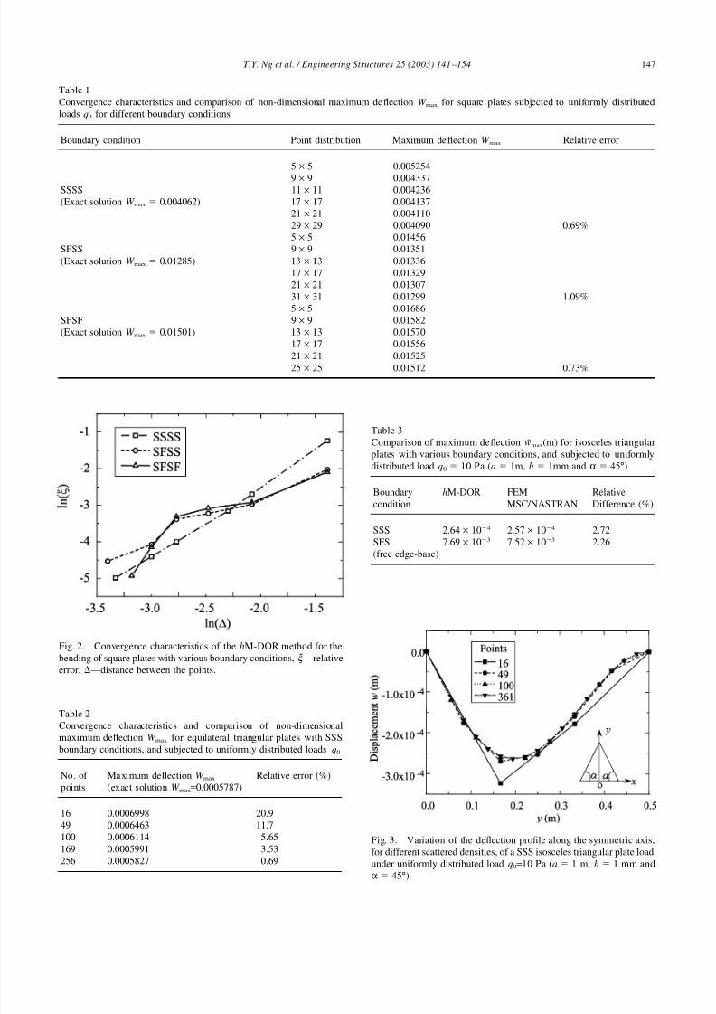
The comparisons for the square plates of various
boundary conditions are shown in Table 1. Three caseshave been considered, namely, SSSS, SFSS and SFSF,
where S represents a simply-supported edge while F rep-
resents a free edge. Presently obtained results for the
non-dimensional maximum deflections W max
w̃ max( x, y) D0 / (q0a4) of the square plates subjected to uni-
formly distributed loads q0 are compared with the exactsolutions. It is observed that as the number of regular
Fig. 1. Geometrical shapes of the thin plates and the distribution of the scattered points—(a) square, (b) triangular and (c) trapezoidal.
scattered points is increased, the relative errors decrease
in a monotonic manner, and generally being less than
1.1% for converged solutions. The convergence charac-
teristics in the form of the variation of the relative error
x with the distance between the points are shown in
Fig. 2, which validates the numerical stability of the
developed hM-DOR method.The comparisons for the different triangular plates are
shown respectively in Table 2 (a simply-supported equi-
lateral triangular plate—SSS) and Table 3 (an isosceles
triangular plate with all three edges simply-supported—SSS or with two simply-supported edges and one free
edge—SFS, the free edge being the base). Table 2 com-
pares the computed non-dimensional maximum deflec-
tions W max w̃ max( x, y) D0 / (q0a4) of the equilateral tri-
angular plates subjected to uniformly distributed loads
q0 with the exact solutions, and it is observed that as the
number of scattered points is increased, the relative
errors decrease monotonically, reaching a discrepancy of less than 0.7% when convergence is attained. Table 3
compares the computed maximum deflections w̃ max( x, y)
by the developed hM-DOR method with the FEM results
obtained through the commercial solver
MSC/NASTRAN, for an isosceles triangular aluminum
plate (a 1 m, α 45°) with two different combi-
nations of boundary conditions (SSS and SFS), and the
discrepancy between the two sets of results is less than
2.8%. Also for different densities of the scattered points,
Fig. 3 shows the deflection variation along the sym-
metric axis for a simply-supported isosceles triangular
plate (a 1 m, α 45°). Once again we observe verystable convergence characteristics in the developed hM-
DOR method. Further, the deflection profile shows that
the boundary conditions have been properly enforced.
For trapezoidal plates of various boundary conditions
(SSSS/SFSS/SFSF) and geometric parameters, Table 4
shows the numerical comparisons of the computed
maximum deflections w̃ max( x, y) by the developed hM-
DOR method again with the FEM results by commercial
solver MSC/NASTRAN. It is evident that the numerical
results are in close agreement with the FEM analysis,
with discrepancies of less than 2.5%, which is further
evidence of the numerical accuracy and stability of theproposed hM-DOR method.
8/2/2019 A New Hybrid Meshless-differential Order Reduction (hM-DOR)
http://slidepdf.com/reader/full/a-new-hybrid-meshless-differential-order-reduction-hm-dor 7/14
147T.Y. Ng et al. / Engineering Structures 25 (2003) 141 –154
Table 1
Convergence characteristics and comparison of non-dimensional maximum deflection W max for square plates subjected to uniformly distributed
loads q0 for different boundary conditions
Boundary condition Point distribution Maximum deflection W max Relative error
5 × 5 0.005254
9 × 9 0.004337SSSS 11 × 11 0.004236
(Exact solution W max 0.004062) 17 × 17 0.004137
21 × 21 0.004110
29 × 29 0.004090 0.69%
5 × 5 0.01456
SFSS 9 × 9 0.01351
(Exact solution W max 0.01285) 13 × 13 0.01336
17 × 17 0.01329
21 × 21 0.01307
31 × 31 0.01299 1.09%
5 × 5 0.01686
SFSF 9 × 9 0.01582
(Exact solution W max 0.01501) 13 × 13 0.01570
17 × 17 0.01556
21 × 21 0.0152525 × 25 0.01512 0.73%
Fig. 2. Convergence characteristics of the hM-DOR method for the
bending of square plates with various boundary conditions, x—relative
error, —distance between the points.
Table 2Convergence characteristics and comparison of non-dimensional
maximum deflection W max for equilateral triangular plates with SSS
boundary conditions, and subjected to uniformly distributed loads q0
No. of Maximum deflection W max Relative error (%)
points (exact solution W max=0.0005787)
16 0.0006998 20.9
49 0.0006463 11.7
100 0.0006114 5.65
169 0.0005991 3.53
256 0.0005827 0.69
Table 3
Comparison of maximum deflection w̃ max(m) for isosceles triangular
plates with various boundary conditions, and subjected to uniformly
distributed load q0 10 Pa (a 1m, h 1mm and α 45°)
Boundary hM-DOR FEM Relative
condition MSC/NASTRAN Difference (%)
SSS 2.64 × 10⁴
2.57 × 10⁴
2.72SFS 7.69 × 10³ 7.52 × 10³ 2.26
(free edge-base)
Fig. 3. Variation of the deflection profile along the symmetric axis,
for different scattered densities, of a SSS isosceles triangular plate load
under uniformly distributed load q0=10 Pa (a 1 m, h 1 mm and
α 45°).

8/2/2019 A New Hybrid Meshless-differential Order Reduction (hM-DOR)
http://slidepdf.com/reader/full/a-new-hybrid-meshless-differential-order-reduction-hm-dor 8/14
148 T.Y. Ng et al. / Engineering Structures 25 (2003) 141 –154
Table 4
Comparison of maximum deflection w̃ max(m) for trapezoidal plates with various boundary conditions, and subjected to uniformly distributed load
q0 10 Pa (a 4 m, b 2 m, h 1 mm and α 45°)
α Boundary condition hM-DOR FEM MSC/NASTRAN Relative difference (%)
SSSS 1.87 × 10² 1.85 × 10² 1.08
45° SFSS (free edge-base) 1.25 1.22 2.46SFSF 3.01 3.00 0.333
15° 1.05 × 10⁴ 1.04 × 10⁴ 0.962
30° SSSS 2.25 × 10³ 2.23 × 10³ 0.897
60° 1.21 × 101 1.19 × 101 1.68
75° 7.26 × 101 7.24 × 101 0.276
4. Shape control of smart structures via distributed
sensors/actuators
The accuracy and stability of the developed hM-DOR
method have been examined numerically for the thin-
plate bending problem. In this section, we will apply itto examine the deformation shape control of smart struc-tures, which include the bending control of one-dimen-
sional beams and two-dimensional plates through distrib-
uted piezoelectric sensor and actuator layers. In general,
it can be very useful for a design engineer to employ
cost-effective computational tools in order to simulate
numerically the deformation control performance of a
smart structure by changing the location and geometry
of the actuators. The hM-DOR method is applied here
to study the shape control in bending deformation of simply-supported laminated beams and plates with inte-
grated distributed sensors/actuators, so as to demonstrate
the elegance and ef ficiency of the present method for
analyzing smart structures.
4.1. Shape control of a one-dimensional beam in
bending
The governing equation based on bending equilibrium
for a beam integrated with laminated sensors and actu-
ators, as shown in Fig. 4, can be described by [23]
D0
L3d 4W
dX 4 q( X ) p( X )
1
L
d 2
d X 2(
n
m 1
E md 2m( z2im (50)
Fig. 4. Geometry and cross-sectional view (thickness direction) of a beam with integrated actuators and sensors.
z2 jm) Rm( X )d 31V m
hm
)
where the non-dimensional deflection is defined as
W w / L and the non-dimensional coordinate variable
is X x / L ( L being the length of beam). D0 is the effec-tive bending stiffness of the laminated beam, p( X ) thedistributed mechanical load applied to the beam. E m,
hm and d m are respectively the Young’s modulus, thick-
ness and width for the mth-lamina. d 31 is the piezoe-
lectric strain constant, Rm( X ) the electrode profile func-
tion and V m the applied voltage on mth-actuator. zim and
z jm are the distances to middle plane from the upper and
lower surfaces of the mth actuator of the laminated
beam, respectively. The relations of shear force Qshear,
bending moment M , and displacement W according forthe piezoelectric effect of actuators are
M D0d 2W dX 2
n
m 1
E md 2m( z2im (51)
z2 jm) Rm( X )d 31V m
hm, Qshear
d M
d x
The simply-supported boundary conditions are con-sidered for the beam subjected to a uniform load
p( X ) p0. The beam is bonded symmetrically by a pair
of sensor and actuator (see Fig. 4), which are fully
covered by electrodes ( Rm( X ) R0). The right-hand side
term in Eq. (50) thus reduces to q( X ) p0. Applying the

8/2/2019 A New Hybrid Meshless-differential Order Reduction (hM-DOR)
http://slidepdf.com/reader/full/a-new-hybrid-meshless-differential-order-reduction-hm-dor 9/14
149T.Y. Ng et al. / Engineering Structures 25 (2003) 141 –154
hM-DOR methodology, a selected variable is intro-
duced as
F ( X ) d2W
d X 2(52)
and Eq. (50) is subsequently reduced to the following
lower-order differential equation
D0
L3d2F
d X 2 p0. (53)
The simply-supported boundary conditions are
W 0 and D0
LF ( X ) d 31
n
m 1
( z2im (54)
z2 jm) E md 2mV m
hm
Rm( X ) 0 at X 0 and X 1
and by the point collocation technique with fixed repro-
ducing kernel approximation, the approximate solutionsof the non-dimensional beam deflection W ( X ) and intro-
duced variable F ( X ) are constructed by
W ˜ ( X i)
N T
n 1
N n( X i)W n i 1,2,…, N T (55)
F ˜ ( X i)
N T
n 1
N n( X i)F n i 1,2,…, N T (56)
The above differential boundary-value problem is
discretized directly as
D0
L3
N T
n 1
N n, XX ( X i)F n p0( X i) i 1,2,…, N (57)
N T
n 1
N n( X i)F n
N T
n 1
N n, XX ( X i)W n i 1,2,…, N (58)
and at X 0 X N 1
N T
n 1
N n( X N +1)W n 0, D0
L
N T
n 1
N n( X N +1)F n (59)
d 31
n
m 1
( z2im z2 jm) E md
2
mV mhm
Rm( X N +1) 0
and at X 1 X N 2
N T
n 1
N n( X N +2)W n 0, D0
L
N T
n 1
N n( X N +2)F n (60)
d 31 n
m 1
( z2im z2 jm) E md 2mV m
hm
Rm( X N +2) 0
where N is the number of points in the interior compu-
tational domain, and N T is the total number of points,
N T N 2. Rewriting the set of discretized linear
algebraic equations, Eqs. (57) to (60), with respect to the
unknown point values W n and F n, the resulting equations
in matrix form results
M11 N T× N T M12 N T× N T
M21 N T× N T M22 N T× N T
W N T×1
F N T×1 {p2 N T×1} (61)
Eq. (61) is a set of linear algebraic equations, and
through standard procedures, the point values W n andF n can be easily computed and the approximate solution
W ˜ ( X i) (i=1,2,…, N T) for the beam deflection are finally
obtained through Eq. (55).Employing the material properties of a commercial
piezoelectric material PVDF for the numerical simula-
tions, the control influence of the applied electric field is
examined through the deformation of a uniformly loaded
beam. The mechanical and piezoelectric properties of
PVDF are taken as, E 1 E 2 E 3 2 GPa, G12
G13 G23 1 GPa, m12 m13 m23 0, e31 e32 0.046 C/m2, k 33 0.1063 × 10⁹ F/m, with
other parameters being zero. An electro-elastic coupling
parameter Q is defined by
Q Vd 31
p0 L2
( n
m 1
( z2im z2 jm) E md 2m
hm
) (62)
This infers that the deformation shape of the beam can
be controlled by adjusting the defined parameter Q,
which is associated with both the applied electric fieldV and mechanical load p0. In Fig. 5, the comparison of
the controlled non-dimensional deflections W , for the
different electro-elastic coupling parameters Q between
the numerical results by the present hM-DOR method
and the exact analytical solutions of Lin and Hsu [23],
Fig. 5. Comparison with exact results for the controlled non-dimen-
sional deflections W of a uniformly loaded beam with uniform
actuators/ sensors for different electro-elastic coupling parameters Q,
(W 0 p0 L3 / (24 D0)).

8/2/2019 A New Hybrid Meshless-differential Order Reduction (hM-DOR)
http://slidepdf.com/reader/full/a-new-hybrid-meshless-differential-order-reduction-hm-dor 10/14
150 T.Y. Ng et al. / Engineering Structures 25 (2003) 141 –154
shows that present simulations are coincident with the
exact solutions.
4.2. Shape control of a plate with distributed
sensor/actuator patches
Here we consider a symmetric laminated plate inwhich the smart layers are partially covered by square
electrodes acting as the sensors/actuators, as shown inFig. 6(a,b) and 7(a,b). The uncoupled governing equ-
ation for thin plate bending subjected to the mechanical
loading and electric field is written as [24]
D11∂4w
∂ x4 2( D12 2 D66)
∂4w
∂ x2∂ y2 D22
∂4w
∂ y4
q( x, y) p( x, y) (63)
Fig. 6. Effects of central actuator dimension S and electro-elastic coupling parameter Q on the deformation shape of the simply-supported bi-
layer-type square laminated plate subjected to a uniformly distributed load.
n
m 1
[ lmepV mhm zm(em31
∂2 Rm( x, y)
∂ x2 2em36
∂2 Rm( x, y)
∂ x∂ y
em32∂2 Rm( x, y)
∂ y2)]
where zm represents the z-coordinate of the mth-layermidplane, hm the mth-layer thickness, and Dij(i, j
1,2,6) the mechanical bending stiffnesses. If each layer
of laminated plate is isotropic, D11 D22 ( D12
2 D66) D0. p( x, y) is the distributed mechanical load,
V m the applied electric field to the mth-layer and emij the
piezoelectric parameters. lmep is a tracer that defines
whether the applied electric field direction corresponds
to the poling direction of the smart layer, with lmep 1 when the two directions are the same and lm
ep

8/2/2019 A New Hybrid Meshless-differential Order Reduction (hM-DOR)
http://slidepdf.com/reader/full/a-new-hybrid-meshless-differential-order-reduction-hm-dor 11/14
151T.Y. Ng et al. / Engineering Structures 25 (2003) 141 –154
Fig. 7. Effects of central actuator dimension S and electro-elastic coupling parameter Q on the deformation shape of the simply-supported sandwich-
type laminated square plate subjected a uniformly distributed load.
1 if they are opposite. Rm( x, y)is a function to define
the shape and position of mth-layer sensor/actuator
Rm( x, y) [ H ( x x1) H ( x x2)]m·[ H ( y y1) H ( y (64)
y2)]m
where H ( x xi) is the Heaviside step function, which is+1 if x xi and 0 if x xi. Based on the definition of
the Dirac delta function d ( x), we can implement the
derivatives of the function Rm( x, y) with respect to x or y. Usually the Heaviside step function, the Dirac func-
tion and the Dirac-function derivatives are explainedmechanically as a distributed force, concentrated force
and concentrated moment, respectively.
Similarly for the present deformation shape control
problem for plates, we employ the hM-DOR method and
introduce the variable F ( x, y) with the same form as Eq.
(38), and the governing equation, Eq. (63), is reduced to
a lower-order PDE. If the approximate solutions w̃ ( x, y)
and F ˜ ( x, y) are constructed in the same form as Eqs. (42)
and (43), followed by direct discretization through the
point collocation technique with fixed reproducing ker-
nel approximation, the set of reduced governing equa-
tions defined for the interior domain, with respect to theplate deflection w( x, y)and introduced variable F ( x, y)
results in the following discretized form
D0(
N T
n 1
N n, xx( xi, yi)F n
N T
n 1
N n, yy( xi, yi)F n) q( xi, yi)
p( xi, yi) n
m 1
[ lmepV mhm zm(em31
∂2 Rm( xi, yi)
∂ x2
2em36∂2 Rm( xi, yi)
∂ x∂ y em32
∂2 Rm( xi, yi)
∂ y2)]
i 1,2,…, N
(65)

8/2/2019 A New Hybrid Meshless-differential Order Reduction (hM-DOR)
http://slidepdf.com/reader/full/a-new-hybrid-meshless-differential-order-reduction-hm-dor 12/14
152 T.Y. Ng et al. / Engineering Structures 25 (2003) 141 –154
N T
n 1
N n( xi, yi)F n
N T
n 1
N n, xx( xi, yi)wn (66)
N T
n 1
N n, yy( xi, yi)wn i 1,2,…, N
The plate boundary conditions considered here to be
simply-supported, thus the discretized boundary con-
ditions are of the same form as Eq. (46). The correspond-
ing set of discretized linear algebraic equations with
respect to the unknown point values wn and F n is then
set up and solved for simulation of the deformation
shape control of the smart plate structure.
As numerical simulation examples, we consider heretwo types of symmetric square laminated plates with
sensors/actuator patches, which are subjected to a uni-formly distributed load: (1) a bi-layer-type laminated
plate consisting of two layers of piezoelectric material
PXE-52; (2) a sandwich-type laminated plate consistingof an aluminum–alloy core layer with two surface layers
of the commercial piezoelectric material PXE-52. The
Fig. 8. Deformation shape control for a simply-supported equilateral triangular sandwich-type laminated plate subjected to a uniformly distributed
load, via a square actuator with centre point O1gr8(a / 2,√3a / 6), for different electro-elastic coupling parameters Q.
material properties of the aluminum alloy are E 1
E 2 E 3 69 GPa, G12 G13 G23 25.94 GPa,
and m12 m13 m23 0.33. Those of the piezoelectric
material PXE-52 are E 1 E 2 E 3 62.5 GPa,G12 G13 G23 24 GPa, m12 m13 m23 0.3,
d 31 d 32 280 × 1012 m/V, d 33 700 × 1012 m/V,
k 33 3.45 × 10⁸F /m, with other parameters being
zero.
The influences of the electro-elastic coupling para-
meter Q and central actuator dimension S on the defor-
mation shape of the smart square plate subjected to the
uniformly distributed mechanical load p0 are shown
respectively in Fig. 6 for the bi-layer-type laminated
plate and Fig. 7 for the sandwich-type laminated plate.
It is observed from both the figures that the maximum
deflection of laminated plates can be controlled easilyby the distributed sensors/actuators. The deflections
decrease with increasing Q values, and it is also
observed that when Q exceeds a critical value, the
maximum deflection is reduced significantly, see Figs.
6(e) and 7(e). The dimensional effect of the electrode
profile is also examined. By respectively comparing

8/2/2019 A New Hybrid Meshless-differential Order Reduction (hM-DOR)
http://slidepdf.com/reader/full/a-new-hybrid-meshless-differential-order-reduction-hm-dor 13/14
153T.Y. Ng et al. / Engineering Structures 25 (2003) 141 –154
Figs. 6(e) and 7(e) with Fig. 6(f) and 7(f), it is evident
that with increasing electrode profile surface, the defor-
mation shape of the plate can be qualitatively changed
for the same electro-elastic coupling parameter Q.
In order to demonstrate the versatility of the hM-DORmethod, we extend the deformation shape control study
to sandwich-type laminated plates of equilateral triangu-lar (Fig. 8) and trapezoidal (Fig. 9) geometries. In Fig.
8, the deformation shape control of the simply-supported
sandwich-type triangular plate subjected to a uniformly
Fig. 9. Three-dimensional and corresponding contour variations for the deformation shape control of a simply-supported trapezoidal sandwich-
type laminated plate subjected to a uniformly distributed load, via varying the locations of two rectangular actuators ( S1 S2 0.05a × 0.1b)
with centre points O1 and O2, for different electro-elastic coupling parameters Q.
distributed mechanical load is presented for different Q
values. The deformation shape of the plate is controlled
by a single square actuator with centre point O1 at
(a / 2,√3a / 6). Results show intuitively correct character-
istics, and are qualitatively similar to the earlier squareexamples. Fig. 9 shows the corresponding deformation
shape control results for trapezoidal plates. The defor-mation shape of the trapezoidal plate is controlled by
two actuators, both of which have the same rectangular
area S1 S2 0.05a × 0.1b and their centre points O1

8/2/2019 A New Hybrid Meshless-differential Order Reduction (hM-DOR)
http://slidepdf.com/reader/full/a-new-hybrid-meshless-differential-order-reduction-hm-dor 14/14
154 T.Y. Ng et al. / Engineering Structures 25 (2003) 141 –154
and O2 are located at the different local positions, as
shown in Fig. 9. Results here depict the three-dimen-
sional deformation shapes and corresponding contours
respectively for different locations of O1 and O2, and
once again, intuitively correct trends are observed.Further, the deflection mode profiles of the plates,
observed in Fig. 6 to 8, show that the simply-supportedboundary conditions have been properly enforced by thehM-DOR method.
5. Conclusion
Due to dif ficulty in the direct imposition of overlap-
ping boundary conditions encountered by existing collo-
cation-based meshless methods, a new hybrid meshless-
differential order reduction (hM-DOR) method has been
developed here such that these overlapping boundary
conditions can be imposed directly. Based on the order-reduction technique for partial differential equations, thehM-DOR method combines the collocation technique
with a fixed reproducing kernel approximation. Thedeveloped method has been validated for the thin-plate
bending analysis, where thin plates of various geometricshapes and boundary conditions were considered. The
hM-DOR was found to be very accurate and also pos-
sessed high numerical stability. Further, an application
of the hM-DOR method was demonstrated for the simul-
ation of deformation shape control in beams and plates
under uniformly distributed loading and integrated withpiezoelectric sensors/actuators. The numerical results all
point to the newly developed hM-DOR method beingelegant, accurate and numerically stable.
References
[1] Belytschko T, Krongauz Y, Organ D, Fleming M. Meshless
methods: an overview and recent developments. Computer
Methods in Applied Mechanics and Engineering 1996;119:3–47.
[2] Belytschko T, Lu YY, Gu L. Element free Galerkin methods.
International Journal for Numerical Methods in Engineering
1994;37:229–56.
[3] Krongauz Y, Belytschko T. Enforcement of essential boundary
conditions in meshless approximation using finite elements. Com-puter Methods in Applied Mechanics and Engineering
1996;131:133–45.
[4] Liu WK, Jun S, Zhang YF. Reproducing kernel particle methods.
International Journal for Numerical Methods in Engineering
1995;20:1081–106.
[5] Liu WK, Jun S, Li S, Adde J, Belytschko T. Reproducing kernel
particle methods for structural dynamics. International Journal for
Numerical Methods in Engineering 1995;38:1665–79.
[6] Lu YY, Belytschko T, Gu L. A new implementation of the
element free Galerkin method. Computer Methods in Applied
Mechanics and Engineering 1994;113:397–414.
[7] Gunther FC, Liu WK. Implementation of boundary conditions for
meshless methods. Computer Methods in Applied Mechanics and
Engineering 1998;63:205–30.
[8] Mukherjee YX, Mukherjee S. On boundary conditions in the
element free Galerkin method. Computational Mechanics
1997;19:267–70.[9] Hegen D. Element-free Galerkin methods in combination with
finite element approaches. Computer Methods in Applied Mech-
anics and Engineering 1996;135:143–66.
[10] Zhu T, Atluri SN. Modified collocation method and a penalty
formulation for enforcing the essential boundary conditions in the
element free Galerkin method. Computational Mechanics
1998;21:211–22.
[11] Gosz J, Liu WK. Admissible approximations for essential bound-
ary conditions in the reproducing kernel particle method. Compu-
tational Mechanics 1996;19:120–35.
[12] Liew KM, Wu HY, Ng TY. Meshless method for modeling of
human proximal femur: treatment of nonconvex boundaries and
stress analysis. Computational Mechanics 2002;28:390–400.
[13] Liew KM, Ng TY, Wu YC. Meshfree method for large defor-
mation analysis–a reproducing kernel particle approach. Engin-eering Structures 2002;24:543–51.
[14] Liew KM, Wu YC, Zou GP, Ng TY, Elasto-plasticity revisited:
numerical analysis via reproducing kernel particle method and
parametric quadratic programming. International Journal for
Numerical Method in Engineering 2002 (in press).
[15] Liew KM, Ng TY, Zhao X, Reddy JN. Harmonic reproducing
kernel particle method for free vibration analysis of rotating cyl-
indrical shells. Computer Methods in Applied Mechanics and
Engineering 2002 (in press).
[16] Ren J, Liew KM, Kitipornchai S. Numerical simulation of
pseudoelastic behaviour of a shape memory alloy beam via mesh-
free method. Engineering Analysis with Boundary Elements 2002
(in press).
[17] Gingold RA, Moraghan JJ. Smoothed particle hydrodynamics:
theory and applications to non-spherical stars. Monthly Noticesof the Astronomical Society 1977;181:375–89.
[18] Onate E, Idelsohn S, Zienkiewicz OC, Taylor RL. A finite point
method in computational mechanics: applications to convective
transport and fluid flow. International Journal for Numerical
Methods in Engineering 1990;39:3839–66.
[19] Liszka TJ, Duarte CAM, Tworzydlo WW. hp-meshless cloud
method. Computer Methods in Applied Mechanics and Engineer-
ing 1996;139:263–88.
[20] Duarte CA, Oden JT. An h-p adaptive method using clouds. Com-
puter Methods in Applied Mechanics and Engineering
1996;139:237–62.
[21] Aluru NR, Li G. Finite cloud method: a true meshless technique
based on a fixed reproducing kernel approximation. International
Journal for Numerical Methods in Engineering 2001;50:2373–
410.[22] Timoshenko S, Woinowsky-Krieger S. Theory of plates and
shells. N ew York: McGraw-Hill Inc, 1959.
[23] Lin CC, Hsu CY. Static shape control of smart beam plates lami-
nated with sine sensors and actuators. Smart Materials and Struc-
tures 1999;8:519–30.
[24] Lee CK. Theory of laminated piezoelectric plates for the design
of distributed sensors/actuators, Part I: Governing equations and
reciprocal relationships. Journal of the Acoustical Society of
America 1990;87:1144–58.