a new inorganic coating for magnesium alloys with superior ... · the second step is an...
TRANSCRIPT

(The work described in this paper was not funded by the U.S. Environmental Protection Agency. The contents do not necessarily reflect the views of the Agency and no official endorsement should be inferred.)
A New Inorganic Coating for Magnesium Alloys with Superior Corrosion Resistance
Alex J. Zozulin Technology Applications Group, Inc. 4957 lolh Avenue South, Grand Forks, ND 58201 Duane E. Bartak University of Norrhem Iowa, Depamnent of Chemistry CedarFalls. IA 50614
INTRODUCTION
Magnesium, the sixth most abundant element in the earth's crus& is the lightest of all commonly used sauctural metals. Having a density of only 1.74 &". it is one and one- half times lighter than aluminum, approximately four times lighter than zinc or steel and is comparable in weight to perhalogenated or mica and asbestos Nled plastics. Although pure magnesium is too soft for structural use, the addition of other elements such as aluminum. zinc, manganese and rare earths have produced alloys with enhanced chemical and physical properties. Alloys of magnesium have found considerable use in applications where weight saving is imponant. The automotive industry has been looking increasingly towards magne- sium for reducing vehicle weight. thus improving fuel economy, and is currently the major user of magnesium die cast parts. For example. a weight reduction of 125 lb. will yield a he1 economy improvement of 0.2 to 0.5 miles per gallon in the EPA Combined City- Highway tesL1 h a recent perspective of magnesium in automobiles more than forty pro- duction applications of magnesium alloys on US cars are listed? Other industries which benefit from magnesium's low weight include power tools, computers, recnational equip- ment and aerospace. In addition to it's low weight other advantageous propxies include a high-strength-to-weight ratio, excellent dimensional stability, high impact resistance, good creep strength as well as high thermal and electrical conductivity. In addition, magnesium and its alloys are recyclable and present no toxicity hazard?
Pure magnesium metaJ is a reactive metal and thus is easily oxidized. This oxidation or corrosion. galvanic as well as surface, is often the major obstacle against the use of mag- nesium in aggressive corrosive environments. However, through the use of high purity alloys with a low content of iron, nickel and copper, satisfactory performance may be achieved with respect to surface corrosion."' For example, the corrosion rate in salt spray (ASTh4 B117) of high punty AZ91Db and Ah160'. both die cast alloys. range from 1-12 mpy and less than 20 mpy, respectively, while two sand cast alloys. AZ91E and -3, exhibit similar rates of 5 mpy' and 8-16 mpyg. respectively. other commonly used alloys. such as ZE41A. demonstrate considerably higher corrosion rates. The corrosion rate of ZE4lA has been reported to be. greater than 400 mpy." The utilization of these alloys. par- ticularly in aggressive environments. will require the application of surface treatments to provide additional protection against surface corrosion. In contrast. alloy composition will have a limited influence on galvanic corrosion: however, in this case, the Service perfor- mance will dep&d on the proper design, assembly and surface treatments as well as h e metal purity." 259

In terms of aerospace applications, magnesium alloys, including m 1 A . QE22A and AZ91E are currently used to fabricate main transmission housings and other gear boxes for several helicopters which are used for commercial and mililary purposes. Other parts. which arc cast using these alloys, include intakes and intermediate casing for aircraft engines, housing for auxiliary power uni l~ . canopy frames and speed brakes. In many cases, extremely corrosive environments are encountered and, as a result. high performance coat- ings are required to produce maximum protection against surface and galvanic corrosion whiJe minimizing maintenance.
The surface reatmen[ processes for magnesium alloys which serve as a paint base and a banier towards corrosion can be grouped into two types. The fust type is the chemical conversion coatings which are applied either by immersion, brush on or spray-type process- es while the second type involves an electrochemical anodic process. Table I provides a list of the more commonly employed surface treatments.’2 Though many of the conversion coatings do produce a surface that provides some corrosion protection and can act as a paint base, they are limited in applications on the more reactive sand cast alloys. In addition, the abrasion resistance of these coatings, including the anodic processes. are not pardcularly high. It is interesting to note that most of the treatments shown in Table I also utilize chro- mates in the primary coating or sealing bath. The utilization of chromates plus other materi- als such as cadmium, zinc, lead. copper and many volatile organic compounds (VOCs) has resulted in the EPA idenhfyiig the mefal finishing industry as one of the most significant contributors to environmental poll~tion.’~ As a result. there is a critical need for new coating technologies which will reduce or eliminate chromate based systems yet provide adequate corrosion resistance. abrasion resistance and paint adhesion.
$kmical Trrannmi
u1 Ul %I7
U 19 u2 1 HAE
Iridilc No. IS Bder iu loo0
conversion Conversion
solutwn constjNcI&$
Sodium dichnxnau. Nmc acid Sodium dichrwnau. calcium a magnaium fluoride Ammonium binoondc. sdium chromau. phosphoric acid chromic acid. calcium sulfate chranic acid. fcrric “le. potassium flwiide Poranium hydruxidc. polatsium fluoride. aluminum hydruxidc.sodium phosphalc.
,potassium manganau Chmnic acid, chloride. n i w sdution b p h o m
Recently, a new high performance coating for magnesium alloys has been developed which exhibits improved corrosion protection and abrasion resisfance as well as providing an excellent paint base. 7he coating has been given the uademark, TAG”. and is pro- d u d by an electrochemical process that does not employ chromates. The process and coat- ing characteristics are described herein.
2 6 0

products which may be present on the alloys through the use of the mild alkaline etch. This solution, commonly used to brighten die cast alloys, shows an insignifcant metal loss after a ten minute treatment. The coating process itself consists of two steps. The first step is a simple chemical process in which the magnesium alloy is immersed into a heated solution containing the fluoride ion. This solution applies a layer containing a mixture of magnesium fluoride and oxofluorides and magnesium oxide and serves as a base for the step second. The second step is an electrochemical process in which the magnesium alloy is made the anode in an electrolytic cell.
which supplies a combination ACDC signal to the electrochemical cell. As in other anodization processes, the magnesium alloy is the anode while the stainless coating tank serves as the cathode. The electrolytic process involves the concurrent anodization or oxida- tion of the metal substrate and deposition of inorganic species from the silicate containing electrolyte. As a result of the relatively high voltages, greater than 150V. a spark process develops during the deposition. The sparking action is the result of the applied voltage being greater than the dielectric breakdown voltage of the layer produced in the first-chemical step and the developing coating in the elecndolytic step and produces temperatures which have been estimated to be greater than lo00 C . These localized high temperatures result in the fusion of silicate and oxide species onto the metal surface. Although the heat generated from the spark is localized on the surface, the resistive heating of the s$ution requires a cooling system to maintain the electrolyte temperature between 10-20 C. Rgure 2 is a pho- tograph of a magnesium AZ91D panel during the deposition process with the sparks visible on the panel surface. The lifetime of these sparks is typically less than a millisecond.
The electrolytic process is accomplished using a relatively high voltage rectifier
Surface and near surface elemental analysis of the coating by ESCA indicates the
261

EXPERIMENTAL
Evaluation of coating performances was conducted on two magnesium alloys, AZ91D. a die cast alloy, and ZE4lA. a sand cast alloy. All panels used to evaluate corrosion resistance were from the same melt so as to eliminate any variation in base corrosion rate for the bare metal due to variations in alloy composition. AU coatings were applied as per speci- fications either in-house for the Tagnite coating or by an aerospace approved metal coating facility. In addition. all panels were entered into the salt spray chamber together to eliminate variation in chamber conditions.
Coating thicknesses were measured by an eddy current technique using an EMI Intemational EM-2000E instrument which was calibrated with two plastic sheets of certified thickness on an alloy base of similar surface roughness as the panel tested. The arithmetic average roughness height. R,, was measured using a Sheffield type QE promometer amplimeter which was calibrated using a precision reference specimen. Eve measurements were made across the surface of each panel using a 0.03" cut off width and 1.r' piloter stroke length. The five readings were averaged to yield the R. value. Abrasion resistance testing were conducted using a Taber Model 51 30 abraser using two C-17 abrading wheels with lo00 grams of load (ASTM D4060). The C-17 wheels were refacedbefore each test w d after every 1000 cycles using a S-I 1 refacing disk Results are reported as a Taber Wear hdex (TWI) and number of cycles achieved. Corrosion performance testing was performed using a Singleton Model 20 corrosion test chamber operating as per ASTM B117. Panel evaluation was conducted as specified in ASTM D1654. method A and B. Scanning elec- tron photomicrographs were obtained on a Hitachi S-800 scanning electron microscope.
THE COATING PROCESS
The application of the TAG- coating. as is the case with other coating processes. requires good cleaning practices such as those specified in MDL-M-3171.I4 Typically, the cleaning procedure shown in the process flow diagram of Figure 1 is sufficient to degease and clean the surface. In addition. this method is capable of removing minor corrosion
F i p 1. ~nowDiagramforTAG~TrcalmenldMagncsium Albys.
Dwy=aq-- 40.50 C. 1-15 mm..Rinsc
Alkaline Erh 70.80°C. 1-10 min..Rirse
"liyldc Prcvearmen1
lO-lS'C. Rlm
70.95 C. 5-90 mm .Rime
T A G N "
Surface Nwtraluation Prm-TRauneni
50°C. W120 sa"%, Rmsc
262
major constituents include magnesium. silicon, oxygen and fluorine for the coating on both theAZ91D andZE41Aalloyswithaveryminorquantityofpotassium. FortheZE41A alloy, a minor percentage of cerium was detected, a result of the 1% rare earth composition of the alloy. The measured bonding energies indicate that the silicon atom is present in the form of silicate. not as silica. and the fluorine atom exists in its ionic form. This presence of magnesium in the coating indicates the electrolytic process involve the oxidation of the mag- nesium alloy substrate with the concurrent spark deposition of silicate and oxide species on the surface of the magnesium alloy. The oxidation and deposition process also results in a dimensional change for the magnesium alloy part. Cross-sections of panels which were par- tially masked, then coated and subsequently examined by SEM indicate that a dimensional increase of approximately 54% of the coating thickness occurs for the AZ91D alloy as com- pared to 46% for the m l A . These values are similar to those reported for the other two anodic processes. For example, chemical treatment 17 and HAE show an increase of approximately 65 to 75% and 50 to 75%. respectively.”
The thickness of the coating can be varied from two 10 thirty micromeiers by control- ling the current density and the time of the coating process. Typically. the process is per- formed at a constant current density in the range of 5 to IS A/@ with coating times of 10 to 20 minutes for a five to ten micrometer (0.2 to 0.4 mil, type I) thickness and 45 to 75 min- utes for a 20 to 25 micrometer (0.8 to 1.0 mil, type II) thickness. The final voltage, though dependent upon the current density and bath composition, typically ranges from 280 to 320 volts for a type I and 320 to 340 volts for a type II with power requirements of approximate- ly 0.4 and 1.6 k W hr/fr?. respectively.
COATING MORPHOLOGY
I i’
The coating produced during the electrochemical process yields a surface with a finite amount of porosity. The porosity is a result of the evolution of oxygen gas from the oxidation of water or hydroxide ion with the concurrent generation of sparks at the surface. Figure 3A is a scanning electron photomicrograph representing the top view of a 5 microme- ter thick Tagnite coating on a AZ91D test panel at a magnification of 2000 while Figure 4A represents a 22 micrometer thick coating on a ZE4lA test panel. The maximum size of the pores is typically in the range of one to five micrometers for a type I thickness and one to ten micrometers for a type II thickness with the size dependent on the electrolyte composition. concentration and the time of coating process. ?he increase in pore size with coating thick- ness may be attributed to a similar increase in spark size resulting from a greater dielectric breakdown voltage as the deposition process proceeds. Though the surface is porous, the surface texture as measured by profilometer indicates the arithmetic average roughness height (R3 ranges from 25 to 85 microinches for coatings between 2 to 25 micrometers (0.1 to 1 .O mil) thick The value of R, is dependent on the time of deposition or the thickness, only marginally dependent on the current density or the rate of deposition. and is essentially independent of the substrate alloy. For example. a coating thickness of 12.5 micrometers produces a surface with a value of R. from 48 to 53 microinches for current densities between 3 and 15 A/f?.
f inal ly . i t should be noted that although the coating has a porous microsmcturr.
263


cross-sectional views of the coating indicate that the pores do not completely transverse the coating. Figure 39 and 4B are SEM photomicrographs of cross-sections of the TAGNlTE coatings on the same alloys as shown in Figures 3A and 4A. respectively. As can be sen. the coating interface with the metal is quite good with no passageways occurring between the exterior and the base metal. Thus. the coating has the effect of preventing an aggressive environment from contacting the reactive metal substrate which would result in extensive corrosion.
CORROSION PROTECTION AND PAINT ADHESION
With the advent of high purity magnesium alloys, the corrosion rate for the base metal has been significantly reduced as compared to pure magnesium metal. In aggressive environments, however, additional corrosion protection is required and provided by the application of surface coatings. In addition, these coatings also serve as a base for painting. TO test for mrrosion resistance and psnt adhesion, accelerated testing is performed using a salt spray chamber (ASTM B117). Table 111 illustrates some representative 4ta for salt spray testing on the AZ91D and ZE4IA alloys which have been treated with the Tagnite. HAE and chemical treatment 17 coatings. As can be seen. the Tagnite coating provides increased corrosion protection as compared to HAE and chemical treatment 17. For exam- ple, the Tagnite coating on AZ91D with a thickness of 5 to 10 micrometers q y p e I) yields an AS” D1654 (procedure B) rating of 8 after 28 days in salt spray while both HAE and treatment 17 are rated at 5 after just 14 days. It should be noted that the rating is based on the percentage of the total surface area that has failed due to corrosion pits. blisters or any other type of failure present. A rating of 8 represents a 2 to 3% failed area and a 5 denotes 11 to 20% of the area has failed. The best rating is a 10 which corresponds to no failures. The application of a thicker coating provides improved protection as indicated by a rating of 10 for a Type n Tagnite coating after 28 days in salt spray. The ZE4lA alloy also benefits from a Tagnite coaring and. as shown in table m. a type I1 coating typically gives a rating of 9 on panels exposed to salt spray for 14 days while treatment 17 affords only minor protec- tion with over 75% of the area having failed (a rating of zero) after only 2 days. It should be noted that the duration of the corrosion test will be less for the Z 4 1 A alloy than the AZ91D alloy due to the difference in corrosion rates for the base alloys.
Tabk Ill. AslM Dl654 Ratings m AZ91D S u b w 10 Salt Spay.
Tagnik’IAZ9 1 D Type I Tagnik‘lAZ9 ID Type n Tagnitc’LE4lA Type n D o w 17lAZ91D Type 1 D o w 17fAZ91D Type II D o w 171Z541A Type n HAE’IAZ9 1 D Type I
28 days 28 days
14 days 2 days
14 days 14 days
14 days
pOa-& using sodium dihydmgen phosphate pOn.maud using d u m dichromate and ammonium bill&&
8 10 9 5 5 0 5
2 6 5

A comparison of the coating morphologics offers a possible explanation for the greater eITectiveness of the Tagnite coating over HAE and treatment 17 towards corrosion. Cross-sections and surface examination of the coatings by SEM indicate the pores in the Tagnite coating are smaller and more uniform in size and distribution as compared to the other two anodic processes. Funher, the Tagnite coating shows considerably fewer intercon- necting pores which completely transverse dtc coating to the base metal subscrate. In con- tra~~, the coating from aeatment 17 typically produces the decpest pores wifh a high degree of interconnectivity. As a result. the Tagnite coating effectively isolates the magnesium metal substrate from the corrosive environment.
The corrosion resistance of the magnesium alloys may be funher improved by seal- ing the coatings with paints. In lh is case, test panels of the AZ91D alloy which were coated with 10 to 25 micrometers of the Tagnite coating were primed-with a melamine polyester primer and h e n painted with a thermosetting acrylic enamel top coat. ?he panels after being scribed were placed into salt spray for 28 days, with an evaluation of each leg of the scribe beiig performed every seven days. 7he data shown in Table IV, indicate consistently high ratings with no corrosion migration under the scribe or corrosion in the unsm'bed areas; ?he lack of corrosion creepage from scribe is indicative of Lhe good paint adhesion characteris- tics of the coating and may be attributed to its surface morphology.
10-22-3 10 10 10 IO 10-23-3 IO 10 10 10 10-24-1 9 10 10 10 10-25-2 9 10 10 IO 10-29-6 10 10 10 10
10 10 10 10 9
'Tescing(ASTh.T)andcvaluation(ASM D1654)uarcarriedoucbyR.W. Munay.TheDowChemicalCompmy, Tshnical Senice and Development. Lake Jackson Cen~er. Texas.
The effecr of primer and top coat on the corrosion resistance and paint adhesion was also examined on the Zfi4IA alloy. When panels of this alloy. treated with the Tagnite and treatment 17 coatings, are painted with one coat of primer (hIL-M-23377E) and subjected to salt spray for 28 days, extensive corrosion occurs for the treatment 17 coated panels with typical ratings of 3 (procedure B). In contrast. the Tagnite coated panels a n rated as 10 (pro- cedure B). Additionally, panels were also coated with the Tagnite and treatment 17 coatings, painted with one coat of primer (MIL-M-23377E) and a top coat (MIL-C-46168D). In this case, the paint adhesion characteristics were tested by scribing the panels before placing them together in salt spray for 28 days. Due to the higher corrosion rate of lhis alloy, corro- sion pits develop on the scribe for both coating systems; however. the extent of corrosion migration under the scribe or the degree of paint adhesion to the anodic coatings is consider- ably k n e r with the Tagnite coating than with treatment 17. Ratings (procedure A) of 5A and 9A (with a single low value of 7A) are typically obtained for treatment 17 and Tagnite coatings, respectively. 266
. .
ABRASION RESISTANCE
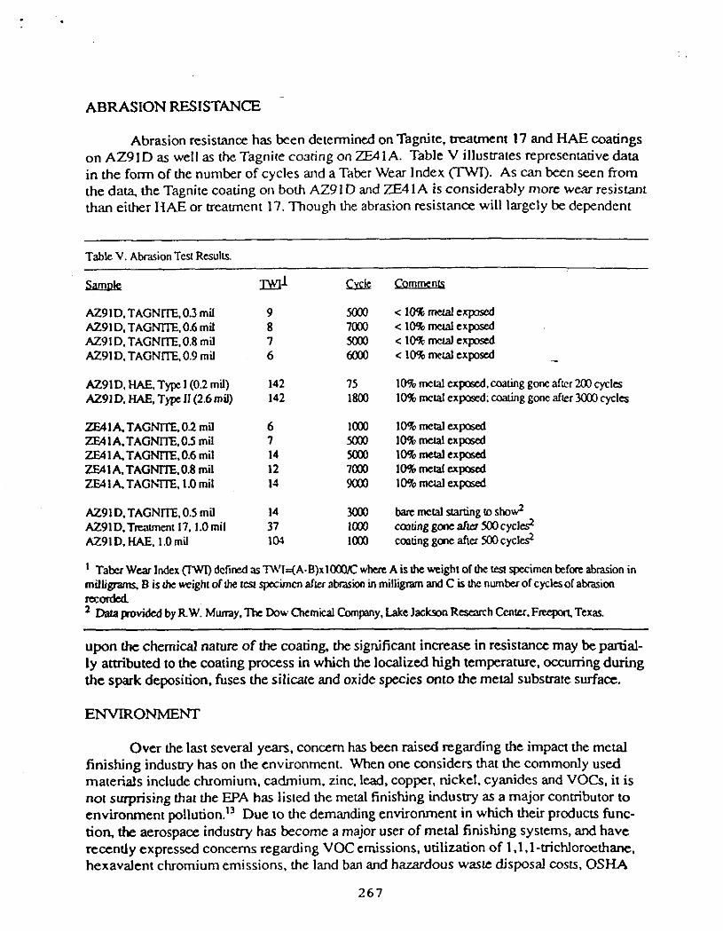
Abrasion resistance has been determined on TagNte. treatment 17 and HAE coatings on AZ91D as well as the Tagnite costing on 2E41A. Table V illustrates representativedata in the form of the number of cycles and a Taber Wear Index (7-W). As can been Seen from the dam, the Tagnite coating on both AZ91 D and ZE41A is considerably more wear resistant than eilher I W E or treatment 17. Though the abrasion resistance will largely be dependent
-~
Table V. Abrasion TeW RcsulLs.
sm&
AZ91D.TAGNrlE.0.3 mil AZ91D.TAGNlTE.0.6 mil AZ91 D. TAGNm. 0.8 mil AZ91D.TAGNITE.0.9 mil
AZ91D.HAE.T~1(0.2mil) ,4291 D. HAE. Tw 11 (2.6 mil)
ZEAlATAGNITE.02mil ZE4IA.TAGNITE.05 mil ZEAlATAG"lE.0.6 mil 7.E41A.TAGNm.0.8 mil ZEA 1 A TAGh7IE. 1.0 mil
AZ91D.TAGNITE,0.5 mil AZ91D.Tmment 17.1.0mil A Z 9 1 D . W . I.Omil
mi s& 9 5ooo 8 7030 7 5030 6 6ooo
142 I5 142 1800
6 loo0 I 5030 14 Moo 12 7000 Id 9030
14 m 37 1030 1w loo0
.-
upon the chemical nature of the coating, the significant increase in resistance may be partial- ly attributed to the coating process in which the localized high temperature. occurring during the spark deposition, fuses the silicate and oxide species onto !he melal substrate surface.
ENVIRONMENT
Over the last several years, concem has been raised regarding the impact the metal finishing industry has on the environment. When one considers that the commonly used materials include chromium. cadmium. zinc, lead, copper, nickel, cyanides and VOCs, it is not surprising that the EPA has listed the metal finishing industry as a major contributor to environment poll~tion. '~ Due to the demanding environment in which their products func- don, the aerospace industry has become a major user of metal finishing systems, and have recently expressed concems regarding VOC emissions, utilization of 1 .I.l-tricNorcethane. hexavalent chromium emissions, the land ban and hazardous waste disposal costs. OSHA
267
compliance and source reduction and recycling. As a result of the increasing inevitable gov- ernment regulation of harardous wastes, the indusny will be required to become more envi- ronmentally responsible through the implementation of waste minimization programs and/or the utilization of less hazardous materials.
Chromaces are one of the principal chemicals used in melal finishing industry. partic- ularly those dealing with magnesium based alloys. The chromate ion is an excellent corro- sion inhibitor. It is used as a paint pigment. employed in chromate conversion coatings, as well as in anodizing baths for aluminum based and magnesium based alloys and as a post- treatment for sealing anodized surfaces. However, chromates are known to be highly toxic and carcinogenic.16 The oral ingestion of 1-2 grams of chromic acid or 6-8 grams of potassi- um dichromate is reponed to cause kidney failure. liver damage. blood disorders and even death." In addition, exposure of chromates to the skin for prolong periods may cause rash- es, blisters and ulcers while inhalation may cause lung cancer. Due to these health risks. OSHA limits insoluble chromates in the air space to 1 mg/m3 per 8 hour day per 40 hour week and has specified that chromate contahhg paints must be labelled w i b lung cancer warning.'*
There are several approaches to the chromium issue. One option is to improve the handling procedures in the work placc so as to comply with the allowable chromate expw sure limits. Since i t is likely that the regulations will only become more restrictive, this alter- native will serve only a a temporary basis. Another alternative is to reduce or eliminate chromate containing waste by the application of new technologies. For example, a study by VanClea~e'~ has resulted in a significant chromium reduction in which chemical treatment 21 was found to be a suitable replacement for treatment 1, both chromate containing solu- tions. thus permitting the elimination of a planned 7600 gallon treatment 1 tank in their new finishing facility.
Though the implementation of chromium reduction programs is clearly needed. the best alternative is the utilization of chromium free materials. Recently. Hinton20*2' has pre- sented several altematives to chromate conversio? coatings and paint pigments for alu- minum based alloys. For magnesium alloy users the elimination of chromate may be more difficult. partly due to the greater chemical reactivity of magnesium. Many of the commonly employed conversion coatings are chromate based (see Table I) while the common cleaning solution for removing corrosion products and old finishes is chromic acid. Further, c m n t specifications such as M1L-M-3171 require the application of chemical treatment 1 to sand cast magnesium alloys for corrosion protection during shipment and storage.
As discussed earlier chemical treatment 17 and HAE are routinely applied to magne- sium alloys when increased corrosion protection is required. Treatment 17 contains approxi- mately 8% by weight sodium dichromate and. although i t is reported that the solution is only infrequently disposed, thus generating only small volumes of chromium containing waste water through dragout. the presence of large processing tanks still results in employee expo- sure and the potential for environmental damage should a spill occur. In addition, even though disposal is infrequent. chromium is inaoduced directly into the environment from the coating itself. Based on the operational parameters for treatment 17 approximately 0.1 to 0.2
268
oz of chromium would bc introduced into the environment per square foot of metal Although HAE is not a chromate containing solution, the coating requires a post-treatment in ammonium bifluoride and sodium dichromate for all grades except grade 1 '' and thus uti- lizes chronuum compounds in the overall process.
A significant chromate reduction may be made by first replacing chromate conver- sion coatings which are used for temporary protection with oil. It has been reported that magnesium components may be stored €rom 1 to 5 years if the alloy is oiled and sealed in a polythene bag containing a desiccant.= Furthermore. the use of oil instead of the conversion coatings will allow the metal surface to be cleaned using alkaline cleaners without relying on chromic acid. Finally, the application of a chromium free coating system such as b e Tagnite coating will eliminate chromates in the anodizing and/or post-treatment baths.
CONCLUSIONS
Reduction and elimination of chromium based systems will be a majorendeavor in the metal finishing industry as the govrmmental regulation of chromium becomes more and more restrictive. For magnesium based alloys chromium reduction may be achieved by replacing the conversion coating used for temporaq storage with oil and by the application of chromium k e coating systems such as Tagnite. The Tagnite system provides greater cor- rosion protection, enhanced paint adhesion and better abrasion resistance than either chemi- cal treatment 17 or HAE.
ACKNOWUEDGEh4ENTS
We wish to thank The Dow Chemical Company, Lake Jackson Research Center for tests conducted on the Tagnite coating as well as Tom Vancleave and Gunter P. Barh of Lockheed Missiles and Space Company for the ESCA data We also wish to thank Jim Suda for performing the SEM work.
REFERENCES
1.
2.
3.
4.
5.
Davis, J. The Potential for Vehicle Weight Reduction Using Magnesium. Society of Automatic Engineers. Paper 910551. 11991. pp. 71-85.
Mezoff. J. G. Magnesium in Automobiles, in Perspective. Society of Automotive Engineers, Paper 800417. 1980. pp. 1-14.
Murray, R. W., and J. E. Hillis. Magnesium Finishing: Chemical Treatment and Coating Practices. SAE, Paper 900791,1990. pp. 1-10.
Aume. T.K. Minimizing Base Metal Corrosion on Magnesium Products. The Effect of Element Dismbution (Structures) on Corrosion Behavior, Proceedings of the 40th World Magnesium Conference, Toronto. 1983.
Hillis, J.E. The Effecs of Heavy Metal Contamination on Magnesium Corrosion 269

performance. S A E , Paper 830523.1983. pp. 1-7.
Reichek, K.N.. K.J. Clark, and J.E. Hillis. Controlling the salt Water Corrosion Performance of Magnesium A291 Alloy, SAE. Paper 85041 7,1985.
Hillis. J.E. and Reichek, K.N. High Purity Magnesium AM60 Alloy: The Critical Containment Limits and the Salt Water Corrosion Performance. S A E . Paper 860288, 1986, pp. 1-8.
The Dow Chemical Company. Heat Treating Sand and Permanent Mold Magnesium Castings. No. 141-552-87. Midland, Michigan, 1987. 10 pp.
Magnesium Elekb-on. Inc. WE43 A Corrosion Resistant Magnesium Casting Alloy for Use up to 570% No. 467A. Lakehurst New Jersey, 1991.4 pp.
Stevenson, A. Metals J.. 39 (5): 16-19. 1987. - Hawke, D.L., J.E. Hillis. and W. Unsworlh. Preventive Practices for Controlling the Galvanic Corrosion of Magnesium Alloys, IMA Technical Committee Report, 1988.
The Dow Chemical Company. Magnesium : Operations in Magnesium Finishing. No. 141479-86R. Midland Michigan, 1990. 56 pp.
Holmes. J. Metal Finishing, 87 (11): 65, 1989.
Military Specification. MIL-M-3 171C. Magnesium Alloy. Processes for Pretreatment and Prevention of Corrosion on, U.S. Government Printing Office, No. 713-153f4659. March 1974.44 pp.
Military Specification. Mn-M-45202C. Magnesium Alloys, Anodic Treatment of, U.S. Government Printing Office. No. 703-023f2048, April 1981.31 pp.
McCoy, D.J. Roc. Second AESFEPA Chromium Colloquium. Miami. Florida, 1990.
6.
7.
8.
9.
10.
11.
I 2.
13.
14.
15.
16.
17.
18.
19.
Toxicological Profile for Chromium, Agency for Toxic Substances. U.S. Public Health Services. Report No. ATSDRP-88f10, July, 1989.
Binner. A. Surface Coatings Australia, 27 (5): 6, 1990.
Vancleave. T.E. Evaluation of Dow 21 to Replaw Dow 1: Chromium Reduction Using Process Consolidation. 7th Annual Aerospace Hazardous Waste Minimization Conference, St. Louis, Missouri, 1992.
Hinton, B.R.W. Metal finishing. 89 (9): 55. 1 9 9 1 .
270
20.
21.
22.
Hinton. B.R.W. Melal Finishing, 89 (10): 15. 1991.
Treatment 17 typically requires revivification after 20 @/gal have been treated with the recommended concentration of 6.7 to 16 odgd of sodium dichromate (the pre- ferred concentration being 13.3 oz/gal>. I f one assumes the bath contains 6.7 odgal of sodium dichromate after 20 f?/gal have been processed and that all the loss chro- mate occurs in the coating, then 6.6 oz/gal of sodium dichromate will be needed to retum the solution IO the preferred conceixmion or 0.1 oz of chromium per square foot of metal treated would be loss to the coating.
Magnesium Elektron Lid. Surface Treamients for Magnesium Alloys in Aerospace and Defence. Twickenham, England. 14pp.
23.
273