a new kid on the block: 2ml70 (rpo m99) 2-mode, part 2 a...
TRANSCRIPT

4 GEARS May/June 2009
A New Kid on the Block: 2ML70 (RPO M99) 2-Mode, Part 2
We left off last time with an overview of the 2ML70 transmission. In this issue,
we’ll explore the inner workings of this unit to see what makes it tick.
Output Speed Sensor (OSS)The output speed sensor is a Hall
Effect-type sensor (figure 1). Internally, the sensor consists of two Hall Effect circuits, allowing it to sense both speed and direction. The two sensor elements in the OSS assembly are spaced about a half-tooth apart.
When the vehicle moves forward, sensor A detects the synch tooth before sensor B. When the vehicle moves in reverse, sensor B detects the synch tooth before sensor A. The sensor is connected to the TEHCM (control solenoid with body and TCM) via the internal wiring harness.
The sensor receives an 8.3–9.3V bias voltage signal from the TEHCM.
by Steve Garrett
A New Kid on the Block:
2ML70 (RPO M99) 2-Mode, Part 2
Figure 1
4-garrettp2.indd 44-garrettp2.indd 4 4/29/09 1:24:13 PM4/29/09 1:24:13 PM

GEARS May/June 2009 5
As the output shaft rotates, the sensor creates a square wave signal. It has a target valve of 8.8V but has an acceptable range of 8.3-9.3V. The electronics in the sensor combine the two signals and output a signal with a different pulse width. The TCM interprets this signal to measure speed and direction.
Internal Mode Switch (IMS)
The IMS (Internal Mode Switch, figure 2) operates similar to other IMS applications. The IMS tells the TEHCM and the Hybrid Powertrain Control Module (HPCM) which gear range you’ve selected, and acts as a P/N safety switch.
The TECHM sends an 8.3–9.3V bias voltage to the IMS on circuits A, B, C and P. The switch is mounted internally on the shift linkage. As the linkage rotates, the contacts of the switch open or close. This creates either a high or low signal on the circuit.
Unlike other applications, the 2ML70 IMS has five additional outputs: R1, R2, D1, D2 and S. These outputs signal the Hybrid Powertrain Control Module (HPCM) regarding IMS direc-tion of movement. This information is used for P/N starting and motor control. (Chart 1)
IMS CIRCUITS/PARAMETER
Selector Position
Park Reverse Neutral Drive Manual
Direction Switch Operating Conditions: Ignition on, range selector in appropriate gear
Direction IMS D1 HIGH HIGH LOW LOW LOW
Direction IMS D2 LOW LOW HIGH HIGH HIGH
Direction IMS R1 HIGH LOW LOW HIGH HIGH
Direction IMS R2 LOW HIGH HIGH LOW LOW
Direction IMS Start LOW HIGH LOW HIGH HIGH
Range Switch Operating Conditions:Ignition On, range selector in appropriate gear.
IMS A LOW LOW HIGH HIGH HIGH
IMS B HIGH LOW LOW LOW HIGH
IMS C HIGH HIGH HIGH LOW LOW
IMS P LOW HIGH LOW HIGH LOW
Always HIGH status: Open/short to voltage
CHART 1
Figure 2
The IMS tells the TEHCM and the
Hybrid Powertrain Control Module (HPCM) which
gear range you’ve selected, and acts
as a P/N safety switch.
4-garrettp2.indd 54-garrettp2.indd 5 5/1/09 3:34:35 PM5/1/09 3:34:35 PM
6 GEARS May/June 2009
A New Kid on the Block: 2ML70 (RPO M99) 2-Mode, Part 2
Control Solenoid with Body and TCM (TEHCM)
The TEHCM is built by Bosch and operates like the 6L80/90/50 applica-tions. The TECHM contains six vari-able bleed solenoids (only five are used):• Two On/Off solenoids• Four pressure switches• One Transmission Fluid
Temperature (TFT) sensor
• Two internal TCM temperature sensors
…and a TCM, all housed in a single, non-serviceable assembly.
The TEHCM bolts to the valve body. You must remove the bottom pan to service it. The TEHCM controls the hydraulic shifts, shift points, and shift feel for the transmission. As with other applications, the TEHCM is program-mable (figure 3, page 8).
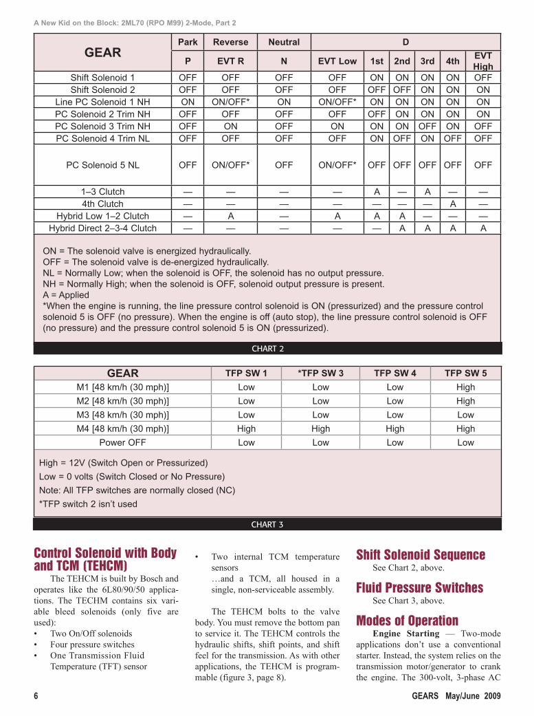
Shift Solenoid SequenceSee Chart 2, above.
Fluid Pressure SwitchesSee Chart 3, above.
Modes of OperationEngine Starting — Two-mode
applications don’t use a conventional starter. Instead, the system relies on the transmission motor/generator to crank the engine. The 300-volt, 3-phase AC
GEARPark Reverse Neutral D
P EVT R N EVT Low 1st 2nd 3rd 4thEVT High
Shift Solenoid 1 OFF OFF OFF OFF ON ON ON ON OFFShift Solenoid 2 OFF OFF OFF OFF OFF OFF ON ON ON
Line PC Solenoid 1 NH ON ON/OFF* ON ON/OFF* ON ON ON ON ONPC Solenoid 2 Trim NH OFF OFF OFF OFF OFF ON ON ON ONPC Solenoid 3 Trim NH OFF ON OFF ON ON ON OFF ON OFFPC Solenoid 4 Trim NL OFF OFF OFF OFF ON OFF ON OFF OFF
PC Solenoid 5 NL OFF ON/OFF* OFF ON/OFF* OFF OFF OFF OFF OFF
1–3 Clutch — — — — A — A — —4th Clutch — — — — — — — A —
Hybrid Low 1–2 Clutch — A — A A A — — —Hybrid Direct 2–3-4 Clutch — — — — — A A A A
ON = The solenoid valve is energized hydraulically.OFF = The solenoid valve is de-energized hydraulically.NL = Normally Low; when the solenoid is OFF, the solenoid has no output pressure.NH = Normally High; when the solenoid is OFF, solenoid output pressure is present.A = Applied*When the engine is running, the line pressure control solenoid is ON (pressurized) and the pressure control solenoid 5 is OFF (no pressure). When the engine is off (auto stop), the line pressure control solenoid is OFF (no pressure) and the pressure control solenoid 5 is ON (pressurized).
GEAR TFP SW 1 *TFP SW 3 TFP SW 4 TFP SW 5
M1 [48 km/h (30 mph)] Low Low Low High
M2 [48 km/h (30 mph)] Low Low Low High
M3 [48 km/h (30 mph)] Low Low Low Low
M4 [48 km/h (30 mph)] High High High High
Power OFF Low Low Low Low
High = 12V (Switch Open or Pressurized)
Low = 0 volts (Switch Closed or No Pressure)
Note: All TFP switches are normally closed (NC)
*TFP switch 2 isn’t used
CHART 2
CHART 3
4-garrettp2.indd 64-garrettp2.indd 6 4/29/09 1:24:53 PM4/29/09 1:24:53 PM

We sell reliability.
Go with a name you know and trust – Precision International.The technological leader in transmission repair for over 30 years.
There’s a lot riding on the quality and reliability of your work. That’s why you can’t take shortcuts whenrepairing a transmission.Whatever make, model or year you’re working on, Precision has the best parts andkits to fix it. All are cross-checked against the latest OEM specs (with changes noted andmade). All are OEquality or better. And all are guaranteed to work. Plus, our huge inventory virtually assures immediate delivery.
You see, at Precision, reliability isn’t just an emptypromise. It’s the heart and soul of our business. . .as well as yours. For more information, give us a call.
www.transmissionkits.com
You can count on usWe also offer outstanding tech support, includingwww.transmissionkits.com – our informativewebsite with continually updated video seminarsfrom leading transmission expert John Parmenter,question and answer forums, complete parts
information and muchmore. So you cantroubleshoot any problemand offer your customersthe very best transmissionsolutions possible. The Problem Solvers.
14 Todd Court Extension, Yaphank, NY 11980(631) 567-2000 • Fax (631) 567-2640 • Toll Free: 800-872-6649Florida Office: 6790 Hillsdale Point, Boynton Beach, FL 33437(561) 734-2332 • Fax (561) 734-2375E-mail: [email protected] www.transmissionkits.com
prec-plcd.indd 7prec-plcd.indd 7 3/13/09 1:52:09 PM3/13/09 1:52:09 PM

8 GEARS May/June 2009
A New Kid on the Block: 2ML70 (RPO M99) 2-Mode, Part 2
motors can rotate the engine to crank-ing speeds that exceed 800 RPM in less than a few hundred milliseconds.
Auto Stop/Auto Start — After the engine’s running, the Hybrid Powertrain Control Module (HPCM) may operate the engine in Auto Stop/Auto Start mode. The Auto Stop feature is designed to reduce emissions output and engine wear, and improve fuel economy in city driving conditions.
Engine Off and Auto Stop modes of operation will be displayed on the tachometer. When the tachometer nee-dle indicates OFF, Auto Stop won’t function. If the tachometer indicates AUTOSTOP, the engine may restart whenever the vehicle meets the proper parameters.
Auto Stop may activate when these conditions are present:• Engine running• Hood closed• ECM isn’t requesting diagnostic
information• Gear selector isn’t in Reverse or
Manual position• Hybrid battery state of charge
exceeds 20%• Hybrid battery voltage, tempera-
ture and power within limits• Engine warm• Drive motor/generators within
temperature limits• Power Inverter Module (PIM) tem-
perature within limits• No Hybrid system faults present• The Hybrid Powertrain Control
Module (HPCM) has determined that engine power isn’t required
The 2-mode system doesn’t require
engine operation to propel the vehicle down the road. The Hybrid Powertrain Control Module (HPCM) may shut the engine off (AUTO STOP) when it deter-mines engine power isn’t required. If the Hybrid Powertrain Control Module (HPCM) determines that additional power is needed, the Auto Start will occur and drive motor 1 will be used to start the engine. This may occur even when the vehicle is in motion if it’s operating in electric mode.
Auto start may activate without notice if any of these conditions occur:• Hood opened• ECM requests the engine to run• Gear selector in Reverse or Manual
position• Hybrid battery charge low• Hybrid battery voltage, tempera-
ture or power limits exceeded• Engine coolant temperature (ECT)
too low• Drive motor/generator temperature
limits exceeded• Power Inverter Module (PIM) tem-
perature limits exceeded• The Hybrid Powertrain Control
Module (HPCM) determined engine power is required
• A Hybrid system fault present
EVT ModeThree electronic drive modes are
available: Reverse, Low and High. High Mode 2 — When you select
High mode, the following occurs:• PCS trim solenoid 3 is commanded
off• Shift solenoid 1 is commanded off• #3 pressure switch opens• #1 pressure switch opens
• #4 pressure switch opens• 2-3-4 clutch is applied• Front motor 1 drives the vehicle
Low Mode 1; Engine Off — When you select Low mode, the following occurs:• PCS trim solenoid 5 is commanded
on• Line pressure PCS is commanded
off• Auxiliary pump is turned on• 1-2 clutch applies• Rear motor 2 drives the vehicle
Low Mode 1; Engine On — When you select Low mode, the following occurs: • PCS 3 is commanded on• PCS 5 is commanded off• 1-2 clutch applies• Front motor 1 starts the engine• Rear motor 2 drives the vehicle if
speeds are less than 25–32 mph
Reverse Mode — When you select Reverse, the following occurs:• PCS 3 is commanded on• 1-2 clutch applies• Rear motor 2 operates to drive the
vehicle in reverse
Regenerative Braking/Blended Braking
When the vehicle is decelerating or coasting, the Hybrid Powertrain Control Module (HPCM) can switch the system into regeneration mode. In this mode the motors act as generators to charge the Hybrid battery. As the motors switch to generator mode, they exert force on the drive train, which helps slow the vehicle.
Blended braking is also available with the 2-mode system. When you apply the brakes, drive motor 2 switch-es to generator mode, which slows the vehicle.
Communication between the Hybrid Powertrain Control Module (HPCM) and Electronic Brake Control Module (EBCM) allows the 2 mode system to interface transparently with the vehicle’s braking system. This fea-ture extends brake life in city driving.
So until next time, remember: Success is built on the ability to do bet-ter than good enough.
Figure 3
The TEHCM bolts to the valve body. You must
remove the bottom pan to service it. The TEHCM
controls the hydraulic shifts, shift points, and shift feel for
the transmission. As with other applications, the TEHCM is
programmable.
4-garrettp2.indd Sec1:84-garrettp2.indd Sec1:8 4/29/09 1:25:25 PM4/29/09 1:25:25 PM

raybestos509.indd 9raybestos509.indd 9 4/29/09 1:39:10 PM4/29/09 1:39:10 PM