a new on-board energy storage system for the rolling stock
TRANSCRIPT
21
A New On-Board Energy Storage System for the Rolling Stock
Masao Yano Toyo University,
Japan
1. Introduction
The increasing environmental problems, such as running out of fossil fuels, global warming, and pollution give a major impetus to the development of the on-board energy storage system for the rolling stock, using such as rechargeable batteries and electric double layer capacitors (EDLCs). In addition to the energy saving, an on-board energy storage system enables to realize a contact-wireless type railcar, by which the landscape is improved and the maintenance cost of overhead contact wires is reduced (Ogiwara, 2010).
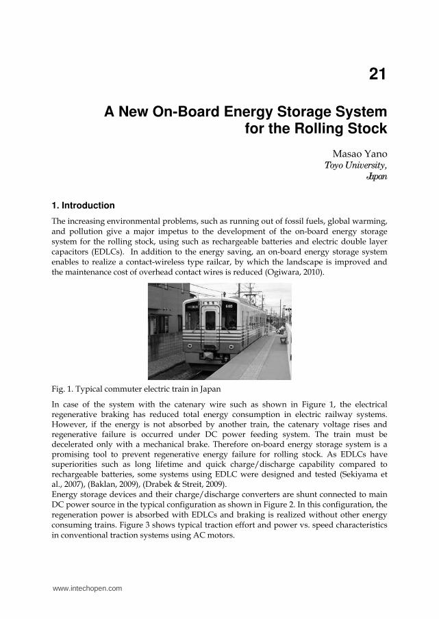
Fig. 1. Typical commuter electric train in Japan
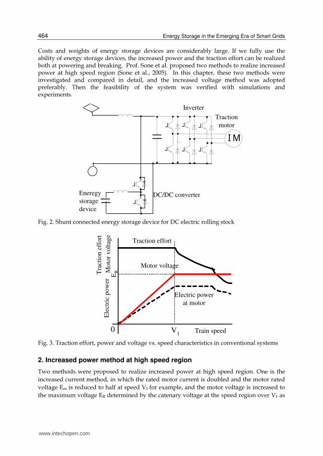
In case of the system with the catenary wire such as shown in Figure 1, the electrical regenerative braking has reduced total energy consumption in electric railway systems. However, if the energy is not absorbed by another train, the catenary voltage rises and regenerative failure is occurred under DC power feeding system. The train must be decelerated only with a mechanical brake. Therefore on-board energy storage system is a promising tool to prevent regenerative energy failure for rolling stock. As EDLCs have superiorities such as long lifetime and quick charge/discharge capability compared to rechargeable batteries, some systems using EDLC were designed and tested (Sekiyama et al., 2007), (Baklan, 2009), (Drabek & Streit, 2009). Energy storage devices and their charge/discharge converters are shunt connected to main DC power source in the typical configuration as shown in Figure 2. In this configuration, the regeneration power is absorbed with EDLCs and braking is realized without other energy consuming trains. Figure 3 shows typical traction effort and power vs. speed characteristics in conventional traction systems using AC motors.
www.intechopen.com
Energy Storage in the Emerging Era of Smart Grids
464
Costs and weights of energy storage devices are considerably large. If we fully use the ability of energy storage devices, the increased power and the traction effort can be realized both at powering and breaking. Prof. Sone et al. proposed two methods to realize increased power at high speed region (Sone et al., 2005). In this chapter, these two methods were investigated and compared in detail, and the increased voltage method was adopted preferably. Then the feasibility of the system was verified with simulations and experiments.
IM
Traction
motor
DC/DC converter
Inverter
Eneregy
storage
device
Fig. 2. Shunt connected energy storage device for DC electric rolling stock
0 V1
Train speed
Electric power
at motor
Traction effort
Motor voltage
ERTra
ctio
n e
ffort
Ele
ctri
c po
wer
Moto
r volt
age
Fig. 3. Traction effort, power and voltage vs. speed characteristics in conventional systems
2. Increased power method at high speed region
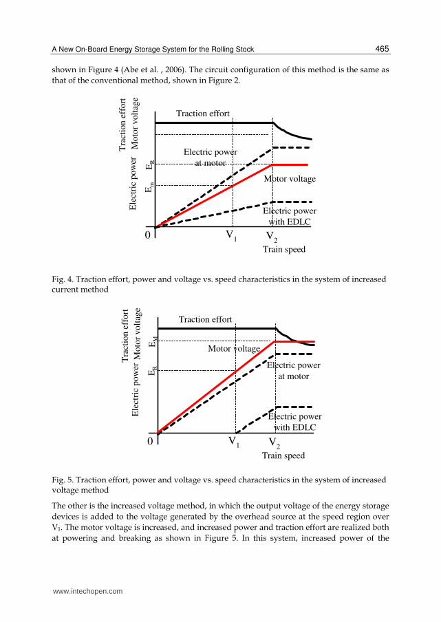
Two methods were proposed to realize increased power at high speed region. One is the
increased current method, in which the rated motor current is doubled and the motor rated
voltage Em is reduced to half at speed V1 for example, and the motor voltage is increased to
the maximum voltage ER determined by the catenary voltage at the speed region over V1 as
www.intechopen.com
A New On-Board Energy Storage System for the Rolling Stock
465
shown in Figure 4 (Abe et al. , 2006). The circuit configuration of this method is the same as
that of the conventional method, shown in Figure 2.
Train speed
Traction effortT
ract
ion e
ffort
Ele
ctri
c pow
er
Electric power
at motor
Electric power
with EDLC
0 V1 V
2
Moto
r v
olt
age
ER
Em
Motor voltage
Fig. 4. Traction effort, power and voltage vs. speed characteristics in the system of increased current method
Train speed
Traction effort
Tra
ctio
n e
ffort
Ele
ctri
c p
ow
er Electric power
at motor
0 V1 V
2
Moto
r volt
age
ER
EM
Motor voltage
Electric power
with EDLC
Fig. 5. Traction effort, power and voltage vs. speed characteristics in the system of increased voltage method
The other is the increased voltage method, in which the output voltage of the energy storage
devices is added to the voltage generated by the overhead source at the speed region over
V1. The motor voltage is increased, and increased power and traction effort are realized both
at powering and breaking as shown in Figure 5. In this system, increased power of the
www.intechopen.com
Energy Storage in the Emerging Era of Smart Grids
466
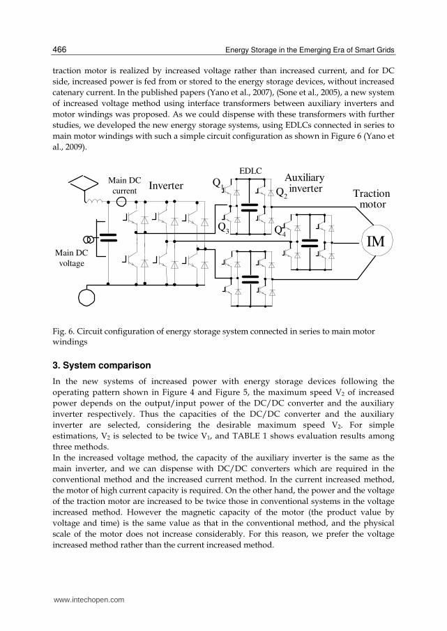
traction motor is realized by increased voltage rather than increased current, and for DC
side, increased power is fed from or stored to the energy storage devices, without increased
catenary current. In the published papers (Yano et al., 2007), (Sone et al., 2005), a new system
of increased voltage method using interface transformers between auxiliary inverters and
motor windings was proposed. As we could dispense with these transformers with further
studies, we developed the new energy storage systems, using EDLCs connected in series to
main motor windings with such a simple circuit configuration as shown in Figure 6 (Yano et
al., 2009).
IM
InverterAuxiliaryinverter
Tractionmotor
EDLCMain DC
current
Main DC
voltage
Q1
Q2
Q3 Q
4
Fig. 6. Circuit configuration of energy storage system connected in series to main motor windings
3. System comparison
In the new systems of increased power with energy storage devices following the
operating pattern shown in Figure 4 and Figure 5, the maximum speed V2 of increased
power depends on the output/input power of the DC/DC converter and the auxiliary
inverter respectively. Thus the capacities of the DC/DC converter and the auxiliary
inverter are selected, considering the desirable maximum speed V2. For simple
estimations, V2 is selected to be twice V1, and TABLE 1 shows evaluation results among
three methods.
In the increased voltage method, the capacity of the auxiliary inverter is the same as the
main inverter, and we can dispense with DC/DC converters which are required in the
conventional method and the increased current method. In the current increased method,
the motor of high current capacity is required. On the other hand, the power and the voltage
of the traction motor are increased to be twice those in conventional systems in the voltage
increased method. However the magnetic capacity of the motor (the product value by
voltage and time) is the same value as that in the conventional method, and the physical
scale of the motor does not increase considerably. For this reason, we prefer the voltage
increased method rather than the current increased method.
www.intechopen.com
A New On-Board Energy Storage System for the Rolling Stock
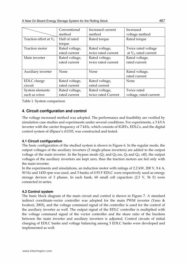
467
Conventional
method
Increased current
method
Increased
voltage method
Traction effort at V2 Half of rated
torque
Rated torque
Rated torque
Traction motor
Rated voltage,
rated current
Rated voltage,
twice rated current
Twice rated voltage
at V2, rated current
Main inverter
Rated voltage,
rated current
Rated voltage,
twice rated current
Rated voltage,
rated current
Auxiliary inverter None None Rated voltage,
rated current
EDLC charge
circuit
Rated voltage,
rated current
Rated voltage,
rated current
None
System elements
such as wires
Rated voltage,
rated current
Rated voltage,
twice rated Current
Twice rated
voltage, rated current
Table 1. System comparison
4. Circuit configuration and control
The voltage increased method was adopted. The performance and feasibility are verified by
simulation case studies and experiments under several conditions. For experiments, a 3 kVA
inverter with the carrier frequency of 7 kHz, which consists of IGBTs, EDLCs, and the digital
control system of dSpace’s rt1103, was constructed and tested.
4.1 Circuit configuration The basic configuration of the studied system is shown in Figure 6. In the regular mode, the
output voltages of the auxiliary inverters (3 single-phase inverters) are added to the output
voltage of the main inverter. In the bypass mode (Q1 and Q2::on, Q3 and Q4: off), the output
voltages of the auxiliary inverters are kept zero, thus the traction motors are fed only with
the main inverter.
In the experiments and simulations, an induction motor with ratings of 2.2 kW, 200 V, 9.4 A,
50 Hz and 1430 rpm was used, and 3 banks of 0.93 F EDLC were respectively used as energy
storage devices of 3 phases. In each bank, 60 small cell capacitors (2.3 V, 56 F) were
connected in series.
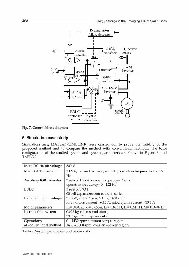
4.2 Control system The basic block diagram of the main circuit and control is shown in Figure 7. A standard
indirect coordinate-vector controller was adopted for the main PWM inverter (Yano &
Iwahori, 2003), and the voltage command signal of the controller is used for the control of
the auxiliary inverter as well. The output signal of the EDLC controller is multiplied with
the voltage command signal of the vector controller and the share ratio of the burdens
between the main inverter and auxiliary inverters is adjusted. Control circuits of initial
charging of EDLC banks and voltage balancing among 3 EDLC banks were developed and
implemented as well.
www.intechopen.com
Energy Storage in the Emerging Era of Smart Grids
468
pT
3
∗
∗
2φ
Regeneration
failure detector
X
PWMInverter
source
IM
speeddetecter
Aux. PWMInverterabc/dq
transform
EDLC
controller
dq/abc
transform
abc/dq
transformd-axis
controller
q-axis
controllerid
iq
id*
iq* +
+
-
-
Bypass
command
DC power
Limmiter
Fig. 7. Control block diagram
5. Simulation case study
Simulations using MATLAB/SIMULINK were carried out to prove the validity of the proposed method and to compare the method with conventional methods. The basic configuration of the studied system and system parameters are shown in Figure 6, and TABLE 2.
Main DC circuit voltage 300 V
Main IGBT inverter 3 kVA, carrier frequency= 7 kHz, operation frequency= 0 - 122 Hz
Auxiliary IGBT inverter 3 sets of 1 kVA, carrier frequency= 7 kHz, operation frequency= 0 - 122 Hz
EDLC 3 sets of 0.93 F, 60 cell capacitors connected in series
Induction motor ratings 2.2 kW, 200 V, 9.4 A, 50 Hz, 1430 rpm, rated d-axis current= 6.62 A, rated q-axis current= 10.5 A
Motor parameters R1= 0.881Ω, R2= 0.658Ω, L1= 0.815 H, L2= 0.815 H, M= 0.0786 H
Inertia of the system 0.025 kg-m2 at simulations, 28.9 kg-m2 at experiments
Operations at conventional method
0 – 1430 rpm: constant-torque region, 1430 – 3000 rpm: constant-power region
Table 2. System parameters and motor data
www.intechopen.com
A New On-Board Energy Storage System for the Rolling Stock
469
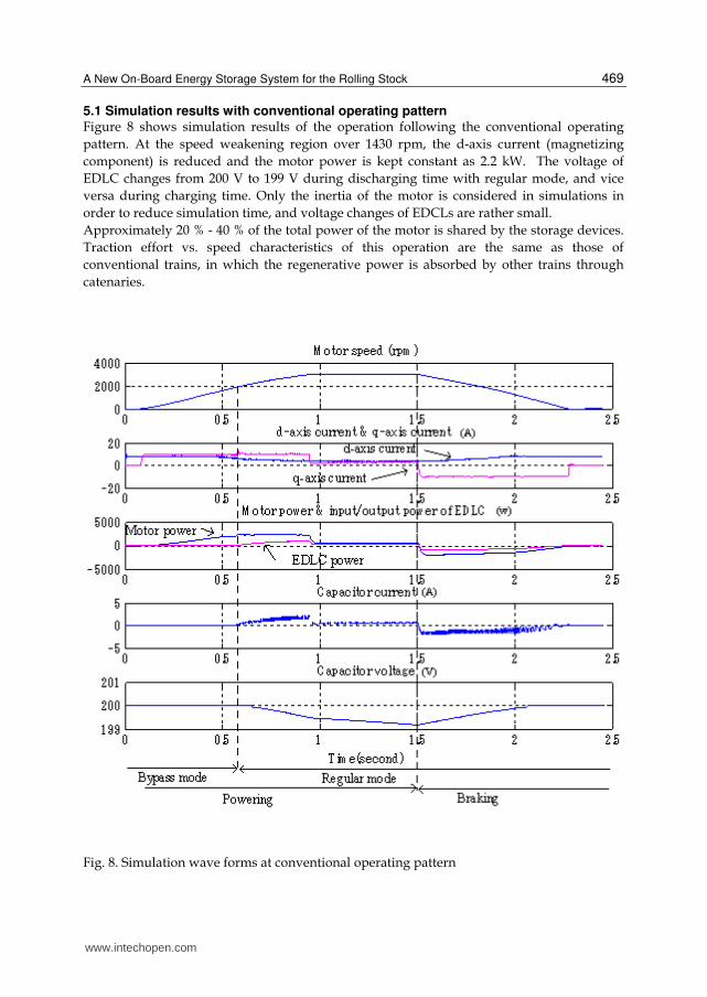
5.1 Simulation results with conventional operating pattern Figure 8 shows simulation results of the operation following the conventional operating
pattern. At the speed weakening region over 1430 rpm, the d-axis current (magnetizing
component) is reduced and the motor power is kept constant as 2.2 kW. The voltage of
EDLC changes from 200 V to 199 V during discharging time with regular mode, and vice
versa during charging time. Only the inertia of the motor is considered in simulations in
order to reduce simulation time, and voltage changes of EDCLs are rather small.
Approximately 20 % - 40 % of the total power of the motor is shared by the storage devices.
Traction effort vs. speed characteristics of this operation are the same as those of
conventional trains, in which the regenerative power is absorbed by other trains through
catenaries.
Fig. 8. Simulation wave forms at conventional operating pattern
www.intechopen.com
Energy Storage in the Emerging Era of Smart Grids
470
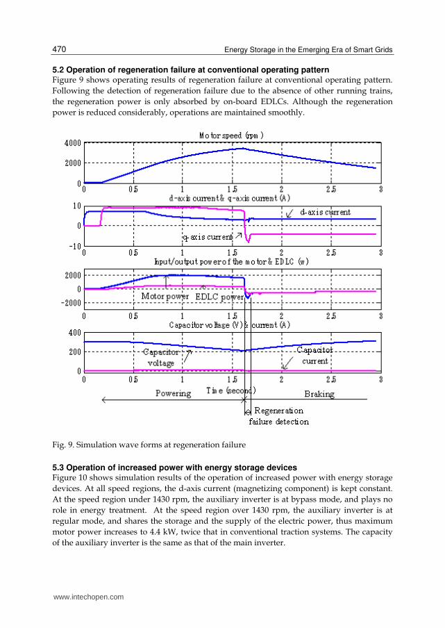
5.2 Operation of regeneration failure at conventional operating pattern Figure 9 shows operating results of regeneration failure at conventional operating pattern.
Following the detection of regeneration failure due to the absence of other running trains,
the regeneration power is only absorbed by on-board EDLCs. Although the regeneration
power is reduced considerably, operations are maintained smoothly.
Fig. 9. Simulation wave forms at regeneration failure
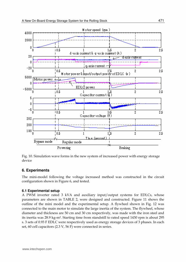
5.3 Operation of increased power with energy storage devices Figure 10 shows simulation results of the operation of increased power with energy storage
devices. At all speed regions, the d-axis current (magnetizing component) is kept constant.
At the speed region under 1430 rpm, the auxiliary inverter is at bypass mode, and plays no
role in energy treatment. At the speed region over 1430 rpm, the auxiliary inverter is at
regular mode, and shares the storage and the supply of the electric power, thus maximum
motor power increases to 4.4 kW, twice that in conventional traction systems. The capacity
of the auxiliary inverter is the same as that of the main inverter.
www.intechopen.com
A New On-Board Energy Storage System for the Rolling Stock
471
Fig. 10. Simulation wave forms in the new system of increased power with energy storage device
6. Experiments
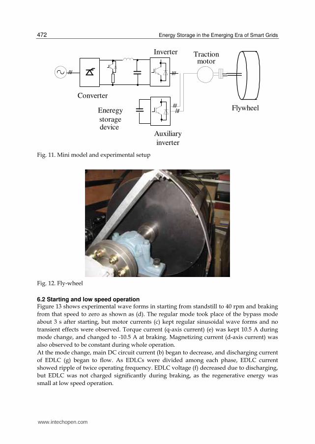
The mini-model following the voltage increased method was constructed in the circuit configuration shown in Figure 6, and tested.
6.1 Experimental setup A PWM inverter rated 3 kVA and auxiliary input/output systems for EDLCs, whose
parameters are shown in TABLE 2, were designed and constructed. Figure 11 shows the
outline of the mini model and the experimental setup. A flywheel shown in Fig. 12 was
connected to the main motor to simulate the large inertia of the system. The flywheel, whose
diameter and thickness are 50 cm and 30 cm respectively, was made with the iron steel and
its inertia was 28.9 kg-m2. Starting time from standstill to rated speed 1430 rpm is about 295
s. 3 sets of 0.93 F EDLC were respectively used as energy storage devices of 3 phases. In each
set, 60 cell capacitors (2.3 V, 56 F) were connected in series.
www.intechopen.com
Energy Storage in the Emerging Era of Smart Grids
472
Inverter
Auxiliary
inverter
Tractionmotor
Flywheel
Converter
Eneregy
storagedevice
Fig. 11. Mini model and experimental setup
Fig. 12. Fly-wheel
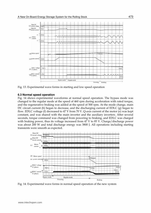
6.2 Starting and low speed operation Figure 13 shows experimental wave forms in starting from standstill to 40 rpm and braking
from that speed to zero as shown as (d). The regular mode took place of the bypass mode
about 3 s after starting, but motor currents (c) kept regular sinusoidal wave forms and no
transient effects were observed. Torque current (q-axis current) (e) was kept 10.5 A during
mode change, and changed to -10.5 A at braking. Magnetizing current (d-axis current) was
also observed to be constant during whole operation.
At the mode change, main DC circuit current (b) began to decrease, and discharging current
of EDLC (g) began to flow. As EDLCs were divided among each phase, EDLC current
showed ripple of twice operating frequency. EDLC voltage (f) decreased due to discharging,
but EDLC was not charged significantly during braking, as the regenerative energy was
small at low speed operation.
www.intechopen.com
A New On-Board Energy Storage System for the Rolling Stock
473
(a)
(b)
(c)
(d)
(e)
(f)
(g)
Fig. 13. Experimental wave forms in starting and low speed operation
6.3 Normal speed operation Fig. 14 shows experimental waveforms at normal speed operation. The bypass mode was changed to the regular mode at the speed of 460 rpm during acceleration with rated torque, and the regenerative braking was added at the speed of 500 rpm. At the mode change, main DC circuit current (b) began to decrease, and the discharging current of EDLC (g) began to flow. EDLC voltage (f) decreased to 47 V from 70 V. Q-axis current of the motor (e) was kept constant, and was shared with the main inverter and the auxiliary inverters. After several seconds, torque command was changed from powering to braking, and EDLC was charged with braking power, thus its voltage increased from 47 V to 85 V. Charge/discharge power was about 200 W and total discharge energy was 3800 J. All operations including starting transients were smooth as expected.
Motor speed
q-axis current
EDLC current
(U phase)
Motor
current
U
V
EDLC voltage
(U phase)
Main DC
circuit voltage
Main DC
circuit current
2.5[A]
70[V]
10[A]
25[A]
25[A]
5[A]
100[V]
47[V]
500[rpm]
1[sec]
Bypass mode Regular mode
Powering Braking
85[V]
(a)
(b)
(c)
(d)
(e)
(f)
(g)
Fig. 14. Experimental wave forms in normal speed operation of the new system
www.intechopen.com
Energy Storage in the Emerging Era of Smart Grids
474
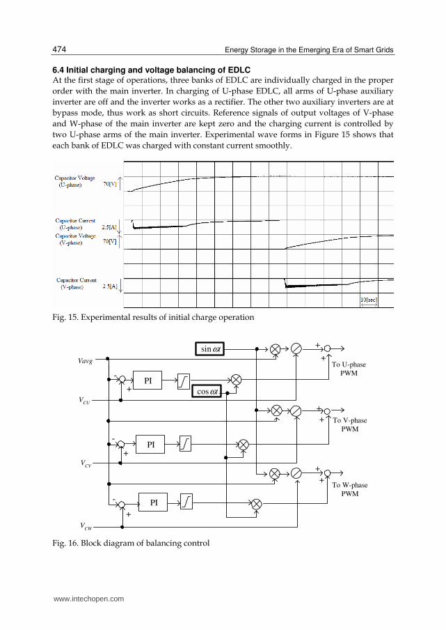
6.4 Initial charging and voltage balancing of EDLC At the first stage of operations, three banks of EDLC are individually charged in the proper
order with the main inverter. In charging of U-phase EDLC, all arms of U-phase auxiliary
inverter are off and the inverter works as a rectifier. The other two auxiliary inverters are at
bypass mode, thus work as short circuits. Reference signals of output voltages of V-phase
and W-phase of the main inverter are kept zero and the charging current is controlled by
two U-phase arms of the main inverter. Experimental wave forms in Figure 15 shows that
each bank of EDLC was charged with constant current smoothly.
Fig. 15. Experimental results of initial charge operation
tωsin
VCU
VCV
VCW
Vavg
PI
PI
PI
tωcos
-
+
+
+
+
+
+
+
+
+
-
-
To U-phase
PWM
To V-phase
PWM
To W-phase
PWM
Fig. 16. Block diagram of balancing control
www.intechopen.com
A New On-Board Energy Storage System for the Rolling Stock
475
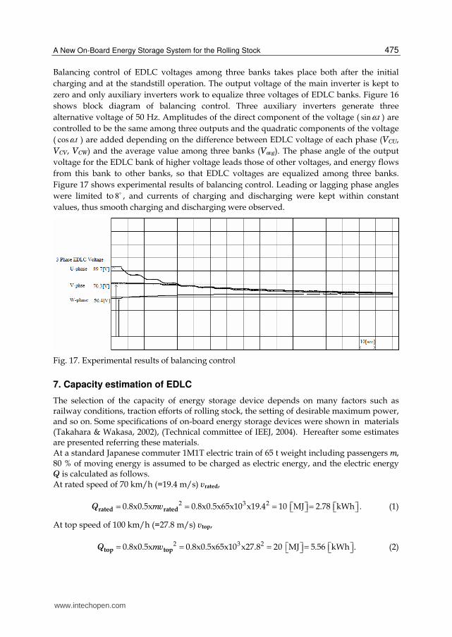
Balancing control of EDLC voltages among three banks takes place both after the initial
charging and at the standstill operation. The output voltage of the main inverter is kept to
zero and only auxiliary inverters work to equalize three voltages of EDLC banks. Figure 16
shows block diagram of balancing control. Three auxiliary inverters generate three
alternative voltage of 50 Hz. Amplitudes of the direct component of the voltage ( tωsin ) are
controlled to be the same among three outputs and the quadratic components of the voltage
( tωcos ) are added depending on the difference between EDLC voltage of each phase (VCU,
VCV, VCW) and the average value among three banks (Vavg). The phase angle of the output
voltage for the EDLC bank of higher voltage leads those of other voltages, and energy flows
from this bank to other banks, so that EDLC voltages are equalized among three banks.
Figure 17 shows experimental results of balancing control. Leading or lagging phase angles
were limited to c8 , and currents of charging and discharging were kept within constant
values, thus smooth charging and discharging were observed.
Fig. 17. Experimental results of balancing control
7. Capacity estimation of EDLC
The selection of the capacity of energy storage device depends on many factors such as railway conditions, traction efforts of rolling stock, the setting of desirable maximum power, and so on. Some specifications of on-board energy storage devices were shown in materials (Takahara & Wakasa, 2002), (Technical committee of IEEJ, 2004). Hereafter some estimates are presented referring these materials. At a standard Japanese commuter 1M1T electric train of 65 t weight including passengers m, 80 % of moving energy is assumed to be charged as electric energy, and the electric energy Q is calculated as follows. At rated speed of 70 km/h (=19.4 m/s) vrated,
2 3 20.8x0.5x 0.8x0.5x65x10 x19.4 10 MJ 2.78 kWhQ mv= = = =⎡ ⎤ ⎡ ⎤⎣ ⎦ ⎣ ⎦rated rated . (1)
At top speed of 100 km/h (=27.8 m/s) vtop,
2 3 20.8x0.5x 0.8x0.5x65x10 x27.8 20 MJ 5.56 kWhQ mv= = = =⎡ ⎤ ⎡ ⎤⎣ ⎦ ⎣ ⎦top top . (2)
www.intechopen.com
Energy Storage in the Emerging Era of Smart Grids
476
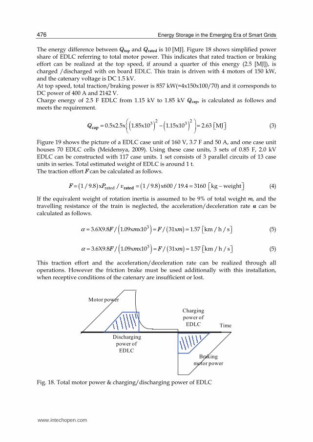
The energy difference between Qtop and Qrated is 10 [MJ]. Figure 18 shows simplified power share of EDLC referring to total motor power. This indicates that rated traction or braking effort can be realized at the top speed, if around a quarter of this energy (2.5 [MJ]), is charged /discharged with on board EDLC. This train is driven with 4 motors of 150 kW, and the catenary voltage is DC 1.5 kV. At top speed, total traction/braking power is 857 kW(=4x150x100/70) and it corresponds to DC power of 400 A and 2142 V. Charge energy of 2.5 F EDLC from 1.15 kV to 1.85 kV Qcap, is calculated as follows and meets the requirement.
( ) ( )2 2
3 30.5x2.5x 1.85x10 1.15x10 2.63 MJQ⎛ ⎞
= − = ⎡ ⎤⎜ ⎟ ⎣ ⎦⎝ ⎠cap (3)
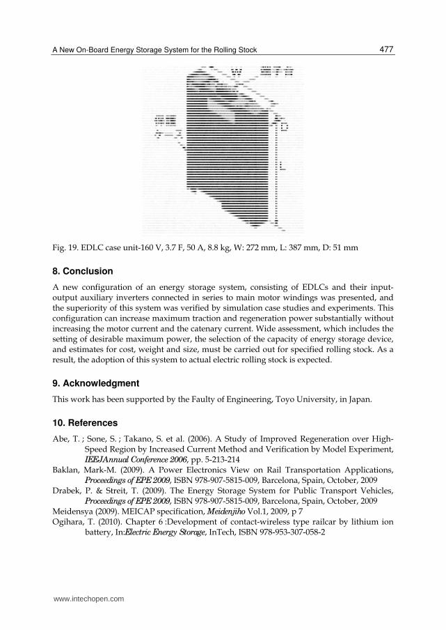
Figure 19 shows the picture of a EDLC case unit of 160 V, 3.7 F and 50 A, and one case unit houses 70 EDLC cells (Meidensya, 2009). Using these case units, 3 sets of 0.85 F, 2.0 kV EDLC can be constructed with 117 case units. 1 set consists of 3 parallel circuits of 13 case units in series. Total estimated weight of EDLC is around 1 t. The traction effort F can be calculated as follows.
( ) ( )rated1 /9.8 x / 1 /9.8 x600 /19.4 3160 kg weightF P v= = = −⎡ ⎤⎣ ⎦rated (4)
If the equivalent weight of rotation inertia is assumed to be 9% of total weight m, and the travelling resistance of the train is neglected, the acceleration/deceleration rate can be calculated as follows.
( ) ( )33.6X9.8 / 1.09x x10 / 31x 1.57 km / h /s F m F mα = = = ⎡ ⎤⎣ ⎦ (5)
( ) ( )33.6X9.8 / 1.09x x10 / 31x 1.57 km / h /sF m F mα = = = ⎡ ⎤⎣ ⎦ (5)
This traction effort and the acceleration/deceleration rate can be realized through all operations. However the friction brake must be used additionally with this installation, when receptive conditions of the catenary are insufficient or lost.
Time
Motor power
Braking
motor power
Discharging
power of
EDLC
Charging
power of
EDLC
Fig. 18. Total motor power & charging/discharging power of EDLC
www.intechopen.com
A New On-Board Energy Storage System for the Rolling Stock
477
Fig. 19. EDLC case unit-160 V, 3.7 F, 50 A, 8.8 kg, W: 272 mm, L: 387 mm, D: 51 mm
8. Conclusion
A new configuration of an energy storage system, consisting of EDLCs and their input-output auxiliary inverters connected in series to main motor windings was presented, and the superiority of this system was verified by simulation case studies and experiments. This configuration can increase maximum traction and regeneration power substantially without increasing the motor current and the catenary current. Wide assessment, which includes the setting of desirable maximum power, the selection of the capacity of energy storage device, and estimates for cost, weight and size, must be carried out for specified rolling stock. As a result, the adoption of this system to actual electric rolling stock is expected.
9. Acknowledgment
This work has been supported by the Faulty of Engineering, Toyo University, in Japan.
10. References
Abe, T. ; Sone, S. ; Takano, S. et al. (2006). A Study of Improved Regeneration over High-Speed Region by Increased Current Method and Verification by Model Experiment, IEEJ Annual Conference 2006, pp. 5-213-214
Baklan, Mark-M. (2009). A Power Electronics View on Rail Transportation Applications, Proceedings of EPE 2009, ISBN 978-907-5815-009, Barcelona, Spain, October, 2009
Drabek, P. & Streit, T. (2009). The Energy Storage System for Public Transport Vehicles, Proceedings of EPE 2009, ISBN 978-907-5815-009, Barcelona, Spain, October, 2009
Meidensya (2009). MEICAP specification, Meidenjiho Vol.1, 2009, p 7 Ogihara, T. (2010). Chapter 6 :Development of contact-wireless type railcar by lithium ion
battery, In:Electric Energy Storage, InTech, ISBN 978-953-307-058-2
www.intechopen.com
Energy Storage in the Emerging Era of Smart Grids
478
Sekijima, Y.; Inui, M.; Aoyama, I. & Monden, Y. (2007). A trial of regenerated energy storage with an electric double layer capacitor for rolling stock, IEEJ-IAS Annual Conference
2007, 1-05-5, pp. I-125-128 Sone, S.; Satoh, T. & Kamiyama, J. (2005). Proposal and Discussion of High-Speed
Regenerative Braking – For Realizing Genuine Pure Electric Braking, The Papers of
Technical Meeting on Transportation and Electric Railway, IEEJ, TER-05-26, pp. 71-74, 2005
Takahara, E. & Wakasa, T. (2002). Electric Double Layer Capacitors for Electric Railway Vehicles, The Papers of Technical Meeting on Transportation and Electric Railway, IEEJ, TER-02-33, pp. 27-30, 2002
Technical committee of IEEJ (2004). Power Electronics Applications in Railways, IEEJ
Technical Report, No. 979, ISSN0919-9195, pp. 64-66 Yano, M. ; Kurihara, M. & Kuramochi, S. (2009). A New On-board Energy Storage System
for the Railways Rolling Stock Utilizing the Overvoltage Durability of Traction Motors, Proceedings of EPE 2009, ISBN 978-907-5815-009, Barcelona, Spain, October, 2009
Yano, M.; Mizumura, T. & Kuramochi, S. (2007). A New Energy Storage System for Railway Rolling Stock Using Transformers Connected in Series to Motor Windings, Proceedings of The IEEE International Electric Machines and Drives Conference, pp. 112-117, Antalya, Turkey, May, 2007
Yano, M. & Iwahori, M. (2003). Transition from Slip-Frequency Control to Vector Control for Induction Motor Drives for Traction Application in Japan, Proceedings of the IEEE
International Conference on Power Electronics and Drive Systems, pp. 1246-1251, Singapore, November, 2003
www.intechopen.com
Energy Storage in the Emerging Era of Smart GridsEdited by Prof. Rosario Carbone
ISBN 978-953-307-269-2Hard cover, 478 pagesPublisher InTechPublished online 22, September, 2011Published in print edition September, 2011
InTech EuropeUniversity Campus STeP Ri Slavka Krautzeka 83/A 51000 Rijeka, Croatia Phone: +385 (51) 770 447 Fax: +385 (51) 686 166www.intechopen.com
InTech ChinaUnit 405, Office Block, Hotel Equatorial Shanghai No.65, Yan An Road (West), Shanghai, 200040, China
Phone: +86-21-62489820 Fax: +86-21-62489821
Reliable, high-efficient and cost-effective energy storage systems can undoubtedly play a crucial role for alarge-scale integration on power systems of the emerging “distributed generation†(DG) and for enablingthe starting and the consolidation of the new era of so called smart-grids. A non exhaustive list of benefits ofthe energy storage properly located on modern power systems with DG could be as follows: it can increasevoltage control, frequency control and stability of power systems, it can reduce outages, it can allow thereduction of spinning reserves to meet peak power demands, it can reduce congestion on the transmissionand distributions grids, it can release the stored energy when energy is most needed and expensive, it canimprove power quality or service reliability for customers with high value processes or critical operations andso on. The main goal of the book is to give a date overview on: (I) basic and well proven energy storagesystems, (II) recent advances on technologies for improving the effectiveness of energy storage devices, (III)practical applications of energy storage, in the emerging era of smart grids.
How to referenceIn order to correctly reference this scholarly work, feel free to copy and paste the following:
Masao Yano (2011). A New On-Board Energy Storage System for the Rolling Stock, Energy Storage in theEmerging Era of Smart Grids, Prof. Rosario Carbone (Ed.), ISBN: 978-953-307-269-2, InTech, Available from:http://www.intechopen.com/books/energy-storage-in-the-emerging-era-of-smart-grids/a-new-on-board-energy-storage-system-for-the-rolling-stock

© 2011 The Author(s). Licensee IntechOpen. This chapter is distributedunder the terms of the Creative Commons Attribution-NonCommercial-ShareAlike-3.0 License, which permits use, distribution and reproduction fornon-commercial purposes, provided the original is properly cited andderivative works building on this content are distributed under the samelicense.