a novel algorithm for frequency dependent modeling of ferrite ring and its optimum design to study...
TRANSCRIPT

RESEARCH ARTICLE
Mehrdad MAJIDI, Hamid JAVADI, Moein MANBACHI
A novel algorithm for frequency dependent modeling of ferritering and its optimum design to study VFTO behaviors withinGIS
© Higher Education Press and Springer-Verlag Berlin Heidelberg 2013
Abstract One of the fundamental issues in gas insulatedsubstations (GIS) which has destructive effects on GISequipment is the very fast transient over-voltages(VFTOs). This paper models a 400/230 kV substation inorder to study the effects of VFTO extensively implemen-ted on EMTP-RV. In addition, the application of ferriterings for suppressing VFTOs is assessed thoroughly. Themain advantage of this paper is its new proposed algorithmaccording to the ferrite ring frequency dependent modelingthat is validated with experimental results. This paperexamines the effects of three compositions of the ferritering on VFTO suppression. Moreover, it estimates thedimension of the ferrite ring based on the SF6 gasinsulation withstand and the maximum effect of ferriterings on VFTO suppression constraint with the COMSOLmultiphysics software. Furthermore, it gains VFTOattenuated percentages due to the installation of the ferritering in different GIS nodes. Finally, it analyzes the offeredVFTO amendment technique in various GIS switchingscenarios.
Keywords comsol multiphysics, EMTP-RV, ferrite ring,gas insulated substations (GIS), transient over-voltage,insulation coordination
1 Introduction
Very fast transient over-voltages (VFTOs) are produced ingas insulated substations (GIS) due to switching breakers,
switchgears, disconnectors and/or earth switches. Theoperation time of disconnectors contacts (DS) is long,sometimes exceeding 0.6 s. Thus, progressive arcs areproduced before switching completion. These arcs can bethe main cause of VFTOs with high frequencies [1–3]. It isseen in past researches that these over-voltages can reachup to 2.5 per units (pu) with a range of hundreds of kHz toMHz [4]. It should be mentioned that the VFTO domainhas completely depended on the GIS configuration [5,6].VFTOs are created in micro-seconds.Hence, VFTOs have high steep wave-fronts. Therefore,
protective equipment such as surge-arresters cannotcontrol these over-voltages. The time responses of zincoxide (ZnO) surge-arresters are longer than the steepnesstime of VFTO. In recent years, various types of plans havebeen offered regarding the over-voltage protection issue.Opening and closing resistors, resistor-capacitor (RC)filters and ferrite ring installation are some of the methodsthat have been studied [7–11]. Ferrite rings can magneti-cally saturate in very high frequencies. An increase infrequency to more than 100 kHz can raise their lossessignificantly but they have negligible losses in powerfrequency ranges.In 1991, ferrite ring initial models were designed [12],
most of which were applied in electronic devices. In 2007,a frequency dependent modeling technique was presented[13], but it was not possible for the authors to design aprecise model of electromagnetic equipment in theelectromagnetic transients program (EMTP) software.For this reason, data analysis and display (DADiSP)software was applied for the modeling of the ferrite ring tostudy its effect on VFTO. Previous researches on ferritering modeling to suppress the VFTO are tabulated in Table1 [13–18]. EMTP-RV has a convenient framework whichprovides a compatible area to implement proposedalgorithm in real networks with specific substations.Although the ferrite ring has not been installed in a realnetwork, a novel method was determined in protecting theGIS bus-bar from VFTOs [14,18]. This is the best
Received April 9, 2013; accepted July 28, 2013
Mehrdad MAJIDI (✉), Hamid JAVADIDepartment of Electrical & Computer Engineering, Power & WaterUniversity of Technology, Tehran, IranE-mail: [email protected]
Moein MANBACHISchool of Engineering Science, Simon Fraser University, 8888University Drive, Burnaby, British Columbia, Canada
Front. Energy 2014, 8(1): 90–100DOI 10.1007/s11708-013-0286-2

technique for suppressing VFTO. Additionally, installingferrite rings will not generate any complexity for the GISbus-bar to design specific insulation schemes [9,13,15,16].However, none of these researches have paid attention tosulfur hexafluoride (SF6) gas insulation withstand and theintensity of consistent electric fields that can be producedby ferrite ring installations due to SF6 gas insulationdistance reduction.
2 Presenting a novel algorithm on ferritering frequency dependent model
The impedance characteristic of ferromagnetic materialsvaries considerably with frequency. The equivalentimpedance of these materials can be expressed in seriesor parallel based on the electric-magnetic modeling ofthese materials [19,20]. This impedance consists of aresistance and an inductance which can be distinguished bytheir permeability coefficients μr(f). It should be mentionedthat the series model can better show the frequencydependency of ferromagnetic materials than the parallelmodel [12]. The frequency dependent impedance (z(jf))which this ring produced against VFTO in the GIS bus-baris mainly caused by permeability coefficient μr(f) and theinductance of the ring (L) [21] which is expressed as
zðjf Þ ¼Rf þ 2πfLf ¼ j2πfLe ¼ 2πf �rðf ÞL¼j2πfL½�ís ðf Þ – j�îs ðf Þ�¼2πfL�îs ðf Þ þ j2πfL�ís ðf Þ¼Rsðf Þ þ j Lsðf Þ,
(1)
where L can be expressed as
L ¼ �0d
2πLn
R
r: (2)
The impedance model in Eqs. (1) and (2) is related toseries electrical models of magnetic materials. Forextracting the real and the imaginary parts of magneticpermeability out of Eq. (1), Eq. (3) should be used.Presented parameters of Eq. (3) can be gained using Eqs.(4) and (5). These calculation steps have been implementedfor three compositions (MnZn, NiZn, 0.8MnZn +0.2NiZn) in Ref. [22]. The result of this study isrepresented in Fig. 1. By applying least squares fittingcurve methods, the amounts of Eqs. (4) and (5) arecalculated, as listed in Table 2. Therefore, ferrite ringfrequency dependent modeling can be implemented basedon Eqs. (1)–(5) in an EMTP software environment. Figure2 depicts the proposed ferrite ring frequency dependentalgorithm.
�rðf Þ ¼ 1þ ~xdwðf Þ þ ~xrotðf Þ, (3)
~xdw fð Þ ¼ xdw f 2dwf 2dw – f 2 þ jβf =mdw
, (4)
~xrot fð Þ ¼ ðfrot þ jαf Þxrotfrotðfrot þ jαf Þ2 – f 2 : (5)
3 Validating proposed algorithm
For testing the accuracy and applicability of the proposed
Table 1 Literature review of presented researches in ferrite ring modeling [13–18]
Reference Applied model for ferrite ringVFTO suppressedpercentage/%
Matching simulatedoutputs of presentedmodels with realmeasured results
Considering SF6allowed electric fieldsin selecting ferritering dimension
Appliedsoftware
[14] 62.00 Very low Not studied PSPICE
[15] 33.75 Not studied Not studied ATP-EMTP
[16] 34.15 Very low Not studied B2SPICE
[17,18] Do not study Not studied Not studied Not Mentioned
[13] More than 33 Very low Not studied DADiSP
This paper 69.20 in average Very high Studied EMTP-RV
Mehrdad MAJIDI et al. Frequency dependent modeling of ferrite ring and its optimum design 91

algorithm, this paper studies the case mentioned in Ref.[21] in order to compare the simulated outputs of theproposed algorithm with those of the case mentioned in
Ref. [21]. A 400 V coaxial is applied in Ref. [21] as anunloaded GIS bus-bar for ferrite ring frequency dependentmodeling in order to study the effects of the ferrite ring onVFTO. Transmission line equations and PI model areapplied to model the GIS bus-bar in the DADiSP software,but in this paper, the constant parameter (CP) model that ispresented in Table 3 is used for modeling the GIS bus-barin an EMTP-RV software environment. In addition, the arcmodel is based on Table 3 (R0 = 1000Ω, τ = 1 ns and r0 =10Ω). All considerations are based on Fig. 3 that presentsthe equivalent circuit in Ref. [21]. As demonstrated in Figs.4 and 5, the proposed algorithm in this paper has accuratesimilar output waveforms, domains, steepness times andfluctuations to the real experimental test in comparisonwith the results in Ref. [21]. These similarities areespecially in VFTO steepness and fluctuations whichcannot be seen in the results in Ref. [21]. As a result, thisinnovative technique is much more accurate than themethod mentioned in Ref. [21].
4 Case study modeling and determiningscenarios for VFTO assessment
This paper takes the Boushehr GIS (400/230 kV) men-tioned in Ref. [23] for case study. Samples of equipmentdestructions have been reported in this substation due totransient over-voltages. Hence, VFTO and ferrite ring
Table 2 Applied parameter values in Eqs. (4) and (5)
Ferromagnetic material MnZn NiZn 0.8MnZn+ 0.2NiZn
xdw 3835 582 6.1
fdw /MHz 1.03 3.05 144.5
βmdw
/MHz8.98 3.61 1280
xrot 1858 1019 11.7
frot /MHz 5.09 854 5100
α 0.97 148 15.2
Fig. 2 Proposed ferrite ring frequency dependent algorithm
Fig. 1 Complex permeability coefficients(a) MnZn; (b) NiZn; (c) 0.8MnZn+ 0.2NiZn [22]
92 Front. Energy 2014, 8(1): 90–100

control function studies are been thoroughly considered. Inaddition, this paper focuses on the accurate modeling of theGIS equipment [24–27]. The schematic diagram of thissubstation is displayed in Fig. 6. The applied models andvalues in VFTO studies are based on Table 3 [1,7]. Various
switching scenarios have been simulated for assessingVFTOs in this substation. Of all simulated situations, fivescenarios are selected as the worst VFTO scenarios basedon Table 4. The trend of maximum VFTO along theswitching way in scenario 1 is depicted in Fig. 9.After passing through the auto-transformer and reaching
the low voltage side, the VFTO domain suppresses. Thissuppression can be seen more clearly when VFTO passesalong the XLPE cable. Moreover, Figs. 8–17 indicate thatthe VFTO domain is considerably great on one side of thebreaker in scenarios 1, 2 and 3, then it suppresses bypassing along the GIS route, and finally it reinforces again.
Table 3 Applied models and values for GIS (400/230 kV) equipment
Equipment Equivalent circuit model
Open 400 kV circuit breaker/Close 400–230 kVcircuit breaker
Open 400 kV switchgear/Close 400 kV switchgear
GIS bus-duct/VT 400–230 kV
Switching arc model R ¼ R0e– t=T þ r0, R0 ¼ 1� 106, τ ¼ 1 ns; r0 ¼ 10 Ω.
Spacer/Surge-arrester
3-Windings transformer
Auto-transformer
Fig. 3 Rearranged electrical equivalent circuit [21]
Mehrdad MAJIDI et al. Frequency dependent modeling of ferrite ring and its optimum design 93

This over-voltage occurs on both sides of the breaker inscenarios 4 and 5 and it rises by spreading along the GISroute extremely. The wave travels in GIS routes without
split and/or the breaker increases the VFTO amplitudeconsistently in all these scenarios so that the voltagedomain has an ascending trend in TOFF11 to AS1 auto-
Fig. 4 VFTOs at the end of the GIS bus without ferrite ring(a) Experimental test; (b) Ref. [21] with DADiSP; (c) proposed model in this paper with EMTP-RV
Fig. 5 VFTOs at the end of the GIS bus applying ferrite ring(a) Experimental test; (b) Ref. [21] with DADiSP; (c) presented model in this paper with EMTP-RV
Fig. 6 Single linediagram of Boushehr GIS (400/230 kV)
94 Front. Energy 2014, 8(1): 90–100
transformer and/or in TOFF10 to AS2 auto-transformer. Itshould be mentioned that if VFTO waves reach AS1 andAS2, they will transfer to the low voltage side with severesuppression.The XLPE cable effect on wave transmitting process is
recuperative which attenuates VFTO amplitudes. TheVFTO domain reaches a maximum of 1.6 pu in scenarios1, 2 and 3. In these scenarios, the maximum over-voltagesoccur in the high voltage side of auto-transformers. Inscenarios 4 and 5, the maximum over-voltages occur on theother side of the breaker. Hence, the maximum over-voltage reaches 3.1 pu in the GTX1 generation terminal ofscenario 5.
5 The optimum design of ferrite ringdimensions based on SF6 gas insulationcoordination and maximum VFTO reductionconstraint
Ferrite ring is a conductor that can be placed between abus-bar conductor and a bus-duct wall, which can reducethe SF6 gas insulation distance. The inner (r) and outer (R)radiuses of ferrite rings determine the amount of insulationdistance reduction. In general, the SF6 gas insulationwithstand level is three times higher than the insulation likethe air. A consistent electric field can be calculated with Eq.(6) [28]:
Eb ¼ 88:5þ 0:65
deðkV=cmÞ: (6)
Reducing the dimension of the ferrite ring can decreaseinductance (L) that will have a less VFTO suppressioneffect. Hence, a trade between the dimension andinductance should be done in order to find the optimumdimensions for ferrite rings. For this reason, two essentialconstraints are considered: maximum VFTO suppressionand allowed SF6 gas electric field. The dimension of theferrite ring has been sized proportional to case study theGIS bus-bar at nominal network voltage through COM-SOL Multiphysics program. The GIS bus-bars have
earthed coaxial aluminum cylinders bus-ducts. The outercylinder has an inner radius (R2 = 24.2 cm). The tubularconductor is the kind of bar that has an outer radius (R1 =7.62 cm). Three changes of the dimension of the ferritering are studied in this paper. First, the inner radius of theferrite ring is 9 cm but the outer radius varies from 10 to 23cm (Appendix I, Cases 1 to 7). In this strategy, themaximum generated field occurs between the ring and theGIS bus-bar (1.38 cm distance between r and R1). Thesecond strategy that allocates 8 to 10 cases of Appendixhas an outer radius of 23 cm but the inner radius variesfrom 10 to 12 cm. Similar to the first mode, the maximumfield generates between the ring and the GIS bus-bar.In the third strategy (Appendix I, Cases 11 to 13), the
ring and the GIS bus-bar connects directly to each other tohave the same potential. The outer radius varies from 20 to20.04 cm. Thus, the maximum field is generated betweenthe ring and the GIS earthed bus-duct. After studying allabove modes (based on Appendix I), the results show thatthe best case for considering both SF6 gas withstand limitand maximum VFTO suppression constraints is when theferrite ring is connected directly to the bus-bar with a20 cm outer radius (Case 13). The electric field strengthand voltage changes in the optimum case are presented inFig. 7.
6 Ferrite ring effect on VFTO suppression
In this section, the proposed idea of frequency dependentmodeling with optimized ferrite ring dimensions has beenimplemented on an applicable case study. Hence, thecompositions of frequency dependent models of MnZn,NiZn and 0.8MnZn+ 0.2NiZn have been compared with aRL constant model in recent researches. Figures 8–17illustrate the results of the five scenarios. If ferrite rings areapplied in GIS bus-bars, the VFTO domain will suppressconsiderably in different points of switching route. Aftercomparing different compositions, it is concluded in thispaper that MnZn is the best composition that has amaximum effect on VFTO improvement. NiZn and
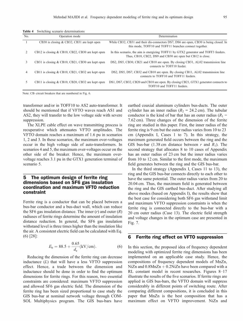
Table 4 Switching scenario determinations
No. Operation mode Determination
1 CB30 is closing & CB32, CB31 are kept open While CB32, CB31 and their dis-connectors DS7, DS6 are open, CB30 is being closed. Inthis mode, TOFF10 and TOFF11 branches connect together.
2 CB12 is closing & CB10, CB22, CB30 are kept open In this scenario, the aim is energizing TOFF11 by GTX2 generator and TOFF3 feeders.Thus, CB10, CB22, DS9 and CB30 are open but CB12 is close.
3 CB31 is closing & CB10, CB21, CB30 are kept open DS2, DS5, CB30, CB21 and CB10 are open. By closing CB31, AL02 transmission lineconnects to TOFF10 feeder.
4 CB11 is closing & CB10, CB21, CB32 are kept open DS2, DS5, DS7, CB32 and CB10 are open. By closing CB11, AL02 transmission lineconnects to TOFF10 and TOFF11 feeders.
5 CB11 is closing & CB10, CB20, CB32 are kept open DS1, DS7, CB32, CB20 and CB10 are open. By closing CB21, GTX1 generator connects toTOFF10 and TOFF11 feeders.
Note: CB–circuit breakers that are numbered in Fig. 6.
Mehrdad MAJIDI et al. Frequency dependent modeling of ferrite ring and its optimum design 95

0.8MnZn+ 0.2NiZn have healing effects on VFTOs. Thedifferences between ferrite ring frequency dependenttechnique (presented in three compositions) and parallelRL models can be assessed in the simulations presented.According to Figs. 8–17, the suppressing the VFTOdomain of the ferrite ring parallel RL model is similar tothat of the 0.8MnZn+ 0.2NiZn frequency dependentmodel. Thus, it has less impact on VFTOs in comparisonwith the MnZn or NiZn models. In scenario 4, existingMnZn and NiZn ferrite rings have limited VFTO near itsinitial value which has a negative domain. In scenario 1, 2and 3 (Figs. 9, 11 and 13), VFTO fluctuations have smoothtrends along the switching route but Figs. 15 and 17 showthat these flat modes cannot be seen in scenarios 4 and 5.By applying ferrite rings in scenario 4, the VFTOsuppression trends will be flat on one side of the switch(AL02 to X6). But on the other side (AS1HV to X6), thisuniform mode cannot be observed. Moreover, on some ofroute points (TOFF10 to X6), the VFTO domain increasesin comparison with the operational mode without theferrite ring. Moreover, in TOFF10 to X6, the VFTOdomain increases in comparison with the operational modewithout the ferrite ring. This unfavorable effect is moretangible when 0.8MnZn+ 0.2NiZn ferrite rings areapplied. Additionally, this ferrite ring effect can be seenin Fig. 17 in X5 point of scenario 5 but this can benegligible in comparison with scenario 4. However, theeffect of MnZn and NiZn ferrite rings on both sides ofswitching locations in scenario 5 can be recognized inFig. 17.In accordance with the remedial effect of a ferrite ring on
GTX1 generator side with 3 pu VFTO, which is better thanNiZn, the lowering effect of the MnZn ferrite ring on theother side of the switch can be negligible. In general, theinstallation of the MnZn ferrite ring is recommended in allscenarios because this composition has a better effect onVFTOs in comparison with other compositions. Table 5presents suppressed percentages of VFTO domains indifferent scenarios applying MnZn ferrite ring. On one sideof switching locations (GTX1 to X5), the MnZn ferrite ringhas a more suppression effect in comparison with NiZn,
but on the other side of the switch (AS1HV to X5), NiZnhas a better suppression effect.
7 Conclusions
This paper proposed an adequate framework for frequency
Fig. 8 VFTOs in TOFF11 point of scenario 1
Fig. 7 Electric field strength and voltage changes in optimum dimensions of ferrite rings
Fig. 9 VFTO domain fluctuations along switching route ofscenario 1
96 Front. Energy 2014, 8(1): 90–100

dependent modeling of ferrite rings and evaluation of thedimension of the ferrite ring. Hence, a relevant case studybased on Ref. [21] was conducted in order to test theaccuracy and the applicability of the model proposed. Theresults obtained using the model proposed are very similar
to the measured results. The MnZn, NiZn and 0.8MnZn+0.2NiZn compositions were applied in frequency depen-dent modeling of the ferrite ring in very fast transientstudies. Moreover, the ferrite ring frequency dependentmodel and the constant RL model, which were consideredin recent researches, were distinguished from each other,
Fig. 13 VFTO domain fluctuations along switching route ofscenario 3
Fig. 14 VFTOs in TOFF5 point of scenario 4
Fig. 15 VFTO domain fluctuations along switching route ofscenario 4
Fig. 10 VFTOs in TOFF11 point of scenario 2
Fig. 11 VFTO domain fluctuations along switching route ofscenario 2
Fig. 12 VFTOs in TOFF10 point of scenario 3
Mehrdad MAJIDI et al. Frequency dependent modeling of ferrite ring and its optimum design 97

and this paper proved the necessity of frequency dependentmodeling of ferrite rings.For determining the dimension of the optimum ferrite
ring to observe SF6 gas sustainable electric fields and themaximumVFTO suppression, a comprehensive simulationwas accomplished using the COMSOL Multiphysicssoftware. When the ferrite ring with an outer radius of20 cm was connected completely to the bus-bar conductor(and have), it kept generating electric fields of SF6 gas onthe admissible range that also has the maximum VFTOsuppression power. In this situation, the ferrite ring had the
maximum dimension with the higher impedance than inother cases. On the other hand, the network studied in thispaper had a better accurate/extensive model than other pastresearches. The VFTOs reached up to 3 pu in theconsidered system in simulations using the EMTP-RVsoftware. In this scenario, the installation of the ferrite ringcould suppress the VFTO domain up to 78%. Simulatedresults illustrated that the MnZn ferrite ring had a bettereffect on VFTO reduction because of its high permeabilityin comparison with the other two. Therefore, applyingMnZn could suppress VFTOs more efficiently.
Appendix: Data of optimum ferrite ring dimension studies
Fig. 17 VFTO domain fluctuations along switching route ofscenario 5
Table 5 VFTO suppressed percentages in different scenarios
Scenario No. Relative point Suppressed percentage/%
1 AS1HV 55.2
2 AS1HV 56.8
3 AS2HV 67.3
4 TOFF5 88.2
5 GTX1 78.5
Strategy No.Without ferrite
L/nH Emax/(kV$cm–1) Eb (SF6)/(kV$cm
–1)r/cm R/cm
1 0 – – – 36.8 88.54
1 9 10 1.61 60.0 88.97
2 9 12 4.38 100.3 88.97
3 9 14 6.73 134.3 88.97
4 9 16 8.77 163.8 88.97
5 9 18 10.56 189.8 88.97
6 9 20 12.17 213.1 88.97
7 9 23 14.30 243.9 88.97
2 8 10 23 12.69 149.4 88.77
9 11 23 11.24 110.6 88.69
10 12 23 9.91 89.4 88.65
Fig. 16 VFTOs in X7 point of scenario 5 with/without ferrite ring
98 Front. Energy 2014, 8(1): 90–100

Notations
References
1. Kumar V V, Thomas M J, Naidu M S. Influence of switching
conditions on the VFTO magnitudes in a GIS. IEEE Transactions on
Power Delivery, 2001, 16(4): 539–544
2. Lu T C, Zhang B. Calculation of very fast transient over voltages in
GIS. In: Proceedings of IEEE/PES Transmission and Distribution
Conference & Exhibition: Asia and Pacific. Dalian, China, 2005, 1–
5
3. Ecklin G, Schlicht D, Plessel A. Over voltages in GIS caused by the
operation of isolators. In: Ragaller K, ed. Surges in High Voltage
Networks. New York: Plenum Press, 1980
4. Liu Q. Study of protection of transformer from very fast transient
over-voltage in 750 kV GIS. In: Proceedings of the Eighth
International Conference on Electrical Machines and Systems
(ICEMS), 2005, 3: 2153–2156
5. CIGRE Working Group. Very fast transient phenomena associated
with GIS. CIGRE Report No. 33-13, 1988, 1–20
6. Meppelink J, Diederich K, Feser K, Pfaff W. Very fast transients in
GIS. IEEE Transactions on Power Delivery, 1989, 4(1): 223–233
7. Tavakoli A, Gholami A, Parizad A, Soheilipour H M, Nouri H.
Effective factors on the very fast transient currents and voltage in the
GIS. In: 2009 IEEE T&D Conference and Exposition: Asia and
Pacific. Seoul, South Korea, 2009, 1–6
8. Xiang Z T, Liu W D, Qian J L, Zhang Y L, Shen Y Z, Wang S P.
High voltage simulation tests of suppressing VFTO in GIS by
magnetic rings. Transaction of China Electrotechnical Society,
2004, 19(7): 1–3
9. Jin L J, Liu W D, Qian J L. Research on the suppression of VFTO in
GIS by ferrite rings. High Voltage Engineering, 2002, 28(7): 1–3 (in
Chinese)
10. Liu W D, Jin L J, Qian J L, Zhang Y L, Shen Y Z, Wang S P.
Possibility of suppressing VFTO in GIS by ferrite rings. Transaction
of China Electrotechnical Society, 2002, 17(4): 22–25
11. Liu W D, Jin L J, Qian J L. Simulation test of suppressing VFT in
GIS by ferrite rings. In: Proceedings of International Symposium of
Electrical Insulating Material. Himeji, Japan, 2001, 245–247
12. Blanken P G, van Vlerken J J L M. Modeling of electromagnetic
systems. IEEE Transactions on Magnetics, 1991, 27(6): 4509–
4515
13. Thomas D E, Wiggins E M, Salas T M, Nickle F S, Wright S E.
Induced transients in substation cables: measurements and models.
IEEE Transactions on Power Delivery, 1994, 9(4): 1861–1868
14. Rama Rao J V G, Amarnath J, Kamakshaiah S. Simulation and
experimental method for the suppressing of very fast transient over-
voltages in a 245 kV GIS using ferrite rings. In: Proceedings of
International Conference on High Voltage Engineering and
Application (ICHVE). New Orleans, USA, 2010, 128–131
15. Li H, Gan L, Li L, Zhou Y, Xu Y. Research on protection measure
for very fast transient over-voltage of GIS. In: Proceedings of 2009
Asia-Pacific Power and Energy Engineering Conference. Wuhan,
China, 2009
Parameters
d Axial depth of a ferromagnetic ring/cm
de Distance between two electrodes in the consistent field/cm
Eb Break down electrical field strength/(kV$cm–1)
fdw Resonance frequencies of DW/Hz
frot Resonance frequencies of ROT/Hz
L Equivalent inductance of ring/H
mdw Effective mass of wall
r Inner radius of a ferromagnetic ring/cm
R Outer radius of a ferromagnetic ring/cm
R1 Conductor outer radius/m
R2 Inner radius of outer cylinder/m
xdw static (or low frequency) susceptibilities for domain wall(DW)
xrot static (or low frequency) susceptibilities for magnetic momentrotation (ROT)
z(jf) Frequency dependent impedance/Ω
α, β Corresponding damping factors
μ0 Permeability of free space (4π� 10-7)
τ Arc time/ns
Variables
f Frequency of current along GIS bus-bar/Hz
Ls(f) Ferrite ring depended frequency series inductance/H
Rs(f) Ferrite ring depended frequency series resistance/Ω
~xdwðf Þ Domain wall component
~xrotðf Þ Magnetic moment rotation
μr(f) Complex permeability
�ís ðf Þ Real part of complex permeability
�}s ðf Þ Imaginary part of complex permeability
(Continued)
Strategy No.Without ferrite
L/nH Emax/(kV$cm–1) Eb (SF6)/(kV$cm
–1)r/cm R/cm
3 11 7.62 20.04 14.74 93.7 88.66
12 7.62 20.03 14.73 91.6 88.66
13 7.62 20 14.71 85.7 88.65
Mehrdad MAJIDI et al. Frequency dependent modeling of ferrite ring and its optimum design 99

16. Rama Rao J V G, Amarnath J, Kamakshaiah S. Accurate modeling
of very fast transient overvoltages in a 245 kV GIS and research on
protection measures. In: Proceedings of the IEEE 2010 Conference
on Electrical Insulation and Dielectric Phenomena (CEIDP), 2010
17. Jin L J, Zheng Y B, Ge P, Zheng Y, Zheng X G. Estimating the size
of ferrite for suppressing VFTO in GIS. In: Proceedings of 2006 the
8th International Conference on Properties and applications of
Dielectric Materials. Bali, Indonesia, 2006, 388–391
18. Jin L J, Zhang Y C, Zheng X G, Shen Y Z. Characteristic parameter
analysis on the suppressing VFTO in GIS by ferrite. In: Proceedings
of 2005 International Symposium on Electrical Insulating Materials.
Kitakyushu, Japan, 2005, 825–828
19. Qian J L, Zhang J R, Gu J Q. Open Shunt Capacity Current and
Small Inductance Current by High Voltage Switch. Beijing: Power
Publisher, 1999 (in Chinese)
20. Watson J K, Amoni S. Using parallel complex permeability for
ferrite characterization. IEEE Transactions on Magnetics, 1989, 25
(5): 4224–4226
21. Li Q, Wu M. Simulation method for the applications of
ferromagnetic materials in suppressing high-frequency transients
within GIS. IEEE Transactions on Power Delivery, 2007, 22(3):
1628–1632
22. Dosoudil R, Usakova M, Slama J, Gruskova A. Frequency variation
of complex permeability in dual ferrite filler single polymeric matrix
composites. In: Proceedings of CSMAG'07 Conference. Kosice,
Slovakia, 2007, 621–624
23. Majidi M, Javadi H, Oskuoee M. Ferroresonance evaluation at
boushehr 230/400 kV GIS substation of Iran’s power network. In:
Proceedings of 2011 International Conference on Electric and
Electronics (EEIC2011). Nanchang, China, 2011
24. Rao M M, Thomas M J, Singh B P. Frequency characteristics of
very fast transient currents in a 245 kV GIS. IEEE Transactions on
Power Delivery, 2005, 20(4): 2450–2457
25. Flohr T, Pfeiffer W, Zender C, Zimmer V. Diagnosis of prebreak-
down phenomena in SF6 in Non-uniform gaps for very fast transient
voltage stress. In: Conference Record of the 1994 IEEE Interna-
tional Symposium on Electrical Insulation. Pittsburgh, USA, 1994,
603–606
26. Amamath J, Paramahamsa D R K, Narasimharao K, Singh B P,
Shrivastava K D. Very fast transient over-voltages and transient
enclosure voltages in gas insulated substations. In: 2003 Annual
Report Conference on Electrical Insulation and Dielectric Phenom-
ena. Albuquerque, USA, 2003, 506–509
27. Pinches D S, Al-Tai M A. Very fast transient overvoltages generated
by gas insulated substations. In: 2008 the 43rd International
Universities Power Engineering Conference. Padova, Italy, 2008,
1–5
28. Kuffel J, Zaengl W S, Kuffel E. High Voltage Engineering:
Fundamentals (Second Edition). Newnes (Butterworth-Heinemann
Ltd.), UK, 2000
100 Front. Energy 2014, 8(1): 90–100